EP3127424B1 - Tuyau d'irrigation au goutte-(a)-goutte à bande - Google Patents
Tuyau d'irrigation au goutte-(a)-goutte à bande Download PDFInfo
- Publication number
- EP3127424B1 EP3127424B1 EP15180002.6A EP15180002A EP3127424B1 EP 3127424 B1 EP3127424 B1 EP 3127424B1 EP 15180002 A EP15180002 A EP 15180002A EP 3127424 B1 EP3127424 B1 EP 3127424B1
- Authority
- EP
- European Patent Office
- Prior art keywords
- strip
- profiles
- water
- section
- hose
- Prior art date
- Legal status (The legal status is an assumption and is not a legal conclusion. Google has not performed a legal analysis and makes no representation as to the accuracy of the status listed.)
- Active
Links
Images


Classifications
-
- A—HUMAN NECESSITIES
- A01—AGRICULTURE; FORESTRY; ANIMAL HUSBANDRY; HUNTING; TRAPPING; FISHING
- A01G—HORTICULTURE; CULTIVATION OF VEGETABLES, FLOWERS, RICE, FRUIT, VINES, HOPS OR SEAWEED; FORESTRY; WATERING
- A01G25/00—Watering gardens, fields, sports grounds or the like
- A01G25/02—Watering arrangements located above the soil which make use of perforated pipe-lines or pipe-lines with dispensing fittings, e.g. for drip irrigation
- A01G25/023—Dispensing fittings for drip irrigation, e.g. drippers
-
- A—HUMAN NECESSITIES
- A01—AGRICULTURE; FORESTRY; ANIMAL HUSBANDRY; HUNTING; TRAPPING; FISHING
- A01G—HORTICULTURE; CULTIVATION OF VEGETABLES, FLOWERS, RICE, FRUIT, VINES, HOPS OR SEAWEED; FORESTRY; WATERING
- A01G25/00—Watering gardens, fields, sports grounds or the like
- A01G25/02—Watering arrangements located above the soil which make use of perforated pipe-lines or pipe-lines with dispensing fittings, e.g. for drip irrigation
-
- B—PERFORMING OPERATIONS; TRANSPORTING
- B05—SPRAYING OR ATOMISING IN GENERAL; APPLYING FLUENT MATERIALS TO SURFACES, IN GENERAL
- B05B—SPRAYING APPARATUS; ATOMISING APPARATUS; NOZZLES
- B05B1/00—Nozzles, spray heads or other outlets, with or without auxiliary devices such as valves, heating means
- B05B1/30—Nozzles, spray heads or other outlets, with or without auxiliary devices such as valves, heating means designed to control volume of flow, e.g. with adjustable passages
- B05B1/3006—Nozzles, spray heads or other outlets, with or without auxiliary devices such as valves, heating means designed to control volume of flow, e.g. with adjustable passages the controlling element being actuated by the pressure of the fluid to be sprayed
-
- B—PERFORMING OPERATIONS; TRANSPORTING
- B05—SPRAYING OR ATOMISING IN GENERAL; APPLYING FLUENT MATERIALS TO SURFACES, IN GENERAL
- B05B—SPRAYING APPARATUS; ATOMISING APPARATUS; NOZZLES
- B05B1/00—Nozzles, spray heads or other outlets, with or without auxiliary devices such as valves, heating means
- B05B1/30—Nozzles, spray heads or other outlets, with or without auxiliary devices such as valves, heating means designed to control volume of flow, e.g. with adjustable passages
- B05B1/3013—Lift valves
-
- Y—GENERAL TAGGING OF NEW TECHNOLOGICAL DEVELOPMENTS; GENERAL TAGGING OF CROSS-SECTIONAL TECHNOLOGIES SPANNING OVER SEVERAL SECTIONS OF THE IPC; TECHNICAL SUBJECTS COVERED BY FORMER USPC CROSS-REFERENCE ART COLLECTIONS [XRACs] AND DIGESTS
- Y02—TECHNOLOGIES OR APPLICATIONS FOR MITIGATION OR ADAPTATION AGAINST CLIMATE CHANGE
- Y02A—TECHNOLOGIES FOR ADAPTATION TO CLIMATE CHANGE
- Y02A40/00—Adaptation technologies in agriculture, forestry, livestock or agroalimentary production
- Y02A40/10—Adaptation technologies in agriculture, forestry, livestock or agroalimentary production in agriculture
- Y02A40/22—Improving land use; Improving water use or availability; Controlling erosion
Definitions
- the present invention relates to a continuous-type emitter for distributing water in a constant flow rate.
- the present invention provides means for water distribution by using a pressure compensating strip such as a continuouos emitter having a first profiles and a second profiles in a regulating section, thus allows for excellent fine-tuning of water flow rate and water pressure regulation.
- irrigation systems There are several types of irrigation systems widely used nowadays, depending on how the water is distributed throughout the field. Some common types of irrigation systems include, for example, surface irrigation, sprinkler irrigation and localized irrigation. In surface irrigation, water is distributed over and across land by gravity, and no mechanical pump involved. In sprinkler irrigation, water is distributed by overhead high-pressure sprinklers or guns from a central location in the field or from sprinklers on moving platforms.
- Drip irrigation is a type of localized irrigation in which drops of water are delivered at or near the root of plants. In this type of irrigation, evaporation and runoff are minimized.
- a type of discrete emitter has been widely used in the drip irrigation system. However, such discrete emitter often consists of multiple parts, thus entails higher production cost, and therefore is less favorable in some instances due to economical reasons.
- Discrete emitters are commonly being used when a larger distance of water outlets are required, for instance a water outlet in about every 20cm or more for each segment water outlet. In this case, discrete emitters are more economically to be used compared to a continuous emitter. When water outlets are needed to be repeated in a shorter distance, for example less than every 20 cm, an elongated emitter is advantageuously a more favorable option.
- some types of continuous emitter may consist of flexible tunnel-like emitter. Said tunnel-like emitter reduces water pressure (and hence water outflow rate) when water pressure of the hose is high.
- Said type of flexible emitters face problems of higher fluctuation of water outflow, as water could bypass the tunnel-like emitter. Fine-tuning of the water outflow and/or water pressure thus fails to be realised in such kind of continuous emitter.
- the inventors of the present invention have surprisingly found out that the above-formulated need can be met by creating a specially-designed strip that is pressure-compensated, elastic, able to fine-tune water flow rate and regulate water pressure as defined in claim 1.
- the strip is provided to be able to simultaneously response, regulate and reduce water flow rate and/or water pressure thanks to an array of specially designed profiles in a regulating section of the strip as claimed. This advantageously allows for a lower cost of production, shorter labyrinth segment, hence allowing for more repetitive labyrinth segments and more water outlets within a shorter distance.
- water is able to be distributed through outlets on the drip irrigation hose in a shorter distance, for example, less than about 10 cm, or even less than 5 cm without affecting the water flow rate of the pressure compensating strip.
- water pressure and water outflow can be better fine-tuned thanks to the different profiles provided in the regulating section of the strip, as water flows through the entire length of labyrinth segment of the strip. Under higher water pressure condition, certain profiles are pushed towards the hose, thereby creating additional barrier within the labyrinth. This enables water pressure to be regulated in an optimal condtion, allowing fine-tuning of water outflow condition and water pressure in the strip.
- the present invention therefore relates to a strip for distributing water, said strip has a repetitive labyrinth segment, wherein a plurality of profiles are provided to the base of the strip, said labyrinth segment comprises: a water input section; a regulating section arranged downstream from the water input section, wherein said regulating section is provided to regulate water flow rate of the strip in response to water pressure of a hose; a discharge section arranged downstream from the regulating section, wherein said discharge section is provided with deflection-resistant reinforcement means.
- the discharge section of the strip according to the present invention allows water to be evenly distributed in a controllable manner, as reinforcement means is provided to reduce frequency of deflection caused by water pressures which exits from the outlets.
- the present invention relates to a pressure compensating drip irrigation hose comprising the aforementioned strip as described herein.
- said strip is made of at least one elastomeric material. This advantageously allows for not only a lower cost of production and easier production, it allows for the drip irrigation hose to be arranged in all possible positions without hindering the flexibility of the hose.
- the water input section is provided with a filter means. This advantageously allows for water to be filtered before entering into the regulating section.
- the distance between the profiles in the input section are less than the distance between the profiles in the regulating section. This advantageously prevents particles larger than the gap between profiles in the water input section to be entered into the regulating section of the strip.
- the strip has two rails, forming side walls of the strip.
- the rails could exist in both the regulating section and the discharge section. This allows water to enter into the strip only through the water input section which has a filter means to filter out certain particles having diameter larger than the gap between profiles of water input section. The filtered water then flows along the labyrinth segment.
- said profiles in the regulating section comprises a first profile, and a second profile, wherein the first profiles are a rectangular-shaped block whereas the second profiles have a wedge shape.
- the first profiles, and the second profile in the regulating section have a barrier-like partition structure extended from the rails of the strip.
- the first profiles are advantageusly designed to set a limitation of a fixed volume of water flowing in the strip. This allows for a certain predetermined water flow rate and/or water pressure flowing in the strip. This prevents voids of the strip to collapse under situation where water pressure is extremely high in the hose.
- the second profiles of the regulating section are advantageously designed to be able to response, regulate and reduce water pressure and/or water flow rate of the strip according to water pressure within the drip irrigation hose.
- water flows along the entire labyrinth segment of the strip.
- the first profiles allow for a maximum volume of water flowing in the strip;
- the second profiles fine-tune water pressure and/or water flow rate of the strip depending on the water pressure of the hose.
- the entire top surface of the first profiles opposite to the base of the strip are connected to an inner part of a hose. This allows said type of first profiles to be fixed permanently between the strip and the hose, thus allowing a fixed volume of water flowing within the strip.
- the profiles in the regulating section are provided in an alternative and regular or irregular fashion throughout the repeated labyrinth segment.
- higher number of the second profiles having a wedge shape than the first profiles could be arranged in the regulating section of the strip.
- less number of the second profiles than the first profiles can be used to achieve the aforementioned goal.
- the discharge section is provided with interconnected reinforcements to increase the resistance of deflection.
- the interconnected reinforcements are provided at the base of the strip. This fortifies said section, allowing for a stronger structure.
- the interconnected reinforcements have height less than the top surface of the rails of the strip so that their influence on disturbing water flow rate is minimised.
- the strip is provided at an inner surface of the drip irrigation hose.
- the strip is made up of material less stiff than the drip irrigation hose so that the flexibility of the hose is not affected by the strip operatively connected within.
- At least one outlet of the hose is provided at the discharge section of the strip. This allows for instaneously water outflow.
- the outlet is an open-end outlet or a slit. Both open end outlet and slit outlet allow water to be emitted easily Furthermore, slit outlets further prevent the roots of the plants from growing into the drip irrigation hose.
- the labyrinth segment of the strip according to the present invention is able to be designed in various length, for instance less than 10cm. It is possible to be less than 8 cm. It is also designed for less than 5 cm without affecting the functionality of the pressure compesating strip and its water flow rate as well as fine-tuning its response to water pressure of the hose.
- a new strip (1) connected to a drip irrigation hose (9) for distributing water is espoused.
- Said strip (1) comprised of a repetitive labyrinth segment (2, 2'), the labyrinth segment has a water input section (3, 3'), followed by a regulating section (4, 4') and subsequently a discharge section (5, 5'), wherein a plurality of profiles (21, 24, 25, 26) are provided to the base (15) of the strip (1), wherein said regulating section (4, 4') is provided to regulate water flow rate of the strip (1) in response of water pressure of a hose. It also simultaneously regulates and responses to water pressure within a certain predetermined water pressure level; a discharge section (5, 5') arranged downstream from the regulating section (4, 4'), wherein said discharge section is provided with deflection-resistant reinforcement means.
- FIG. 1 shows a schematic representation of an exemplary embodiment of the strip not according to the present invention.
- the strip 1 has a repetitive labyrinth segment 2, 2', 2". In each segment of the labyrinth, it is comprised of a water input section 3, 3'; a regulating section 4, 4'; and a discharge section 5, 5'.
- the strip 1 can be made up of any elastomeric materials such as thermoplastic elastomeric synthetic polymer or natural rubber including commonly used polymers such as Polybutadiene, EVA and etc.
- FIG. 2A-C show enlarged top plan of a water input section ( Fig. 2A ), a regulating section ( Fig. 2B ) and a discharge section ( Fig. 2C ).
- a plurality of profiles 21 are provided at the base (15) of the strip 1.
- two rows of closely-aligned profiles 21 are arranged at the water input section 3, 3'.
- a gap GPI exists between each profiles 21 of the water input section.
- the profiles 21 in the water input section 3 serves as filters to filter out any particles larger than the gap GPI between the profiles 21.
- another gap GPII exists between a first profiles 24 and a second profiles 25 in the regulating section 4 ( Fig. 3B ).
- the gap GPI between profiles 21 in the water input section 2 is less than the gap GPII between the first and second profiles 24, 25 in the regulating section.
- This arrangement is able to block any particles larger than the gap GPI in the water input section from entering into the regulating section 3. Therefore, a filter mechanism is provided through the arrangement of various types of profiles 21, 24, 25.
- two rails 22 are located at both sides of the strip 1, namely at the regulating section 4 and at the discharge section 5, but is absent at the water input section 3.
- water from the drip irrigation hose is capable to first enters through the water input section 3, 3' of each of the repeated labyrinth segment 2, 2', followed by entering the regulating section 4, 4' and finally the discharge section 5, 5' which is arranged downstream from the regulating section.
- At least one outlet opening 12 is provided at the drip irrigation hose 9 that sits on top of the discharge section 5, 5'.
- FIG 3A shows a scaled-up bird eye's view of a regulating section 4 having two rails 22 according to the present invention.
- Two different types of profiles 24, 25 are shown.
- the profiles 24, 25 are provided at the base 15 of the strip 1.
- the first profiles 24, which are rectangular shape partitions, have the same height across its top surface 23 as to the top surface of the rails 22.
- the second profiles 25, which are wedge-shape partitions, have gradually reducing height moving to the centre of the strip 1 compared to the side connected to the rails 22.
- the second profiles 25 having a wedge-shaped profile are being sandwiched by two first profiles 24 that have a rectangular-shaped profile (across the top surface opposite to the base 15 having the same height as to the top surface 23 of the rail 22 of the strip 1).
- This arrangement is repeated in a regular (consistent) manner.
- an irregular arrangement with different proportion of first profiles 24 and second profiles 25 can also be realised for different purposes.
- the first profiles 24 serve to limit a certain maximum volume of water flowing in the strip 1. In other words, water pressure of the drip irrigation hose does not affect the reaction of the first profiles 24.
- the top surface of the second profiles 25 (or so-called a flexible profile) opposite to the base 15 of the strip 1 are not connected to the drip irrigation hose 9, hence the second profiles 25 are able to response according to the water pressure of the drip irrigation hose 9 in order to regulate water flow rate as well as water pressure of the strip 1, thanks to its gradually decreasing height towards the centre of the strip.
- Figure 3B shows a longitudinal sectional view of the regulating section (4, 4') of the strip 1.
- the first profiles 24 are connected between the base 15 of the strip 1 and an inner surface of the drip irrigation hose 9.
- the top surface of the second profiles 25 opposite to the base 15 of the strip 1 are not connected to an inner surface of the srip irrigation hose 9.
- a distance M thus exists.
- the second profiles are not being pushed towards the inner surface of the drop irrigation hose.
- water pressure of the drip irrigation hose 9 increases, the second profiles 25 are being pushed towards the inner surface of the drip irrigation hose 9, thus closes the gap M, creating additional labyrinth paths within the existing labyrinth. This allows for a fine-tuned and more consistent method of regulating water outflow rate of the strip.
- first and second profiles can be arranged in order to give a certain water pressure as well as water outflow rate of the strip 1.
- the more number of the second profiles 25 are being provided than the first profiles 24 the larger amount of water would be able to flow within the strip 1, thus a larger response to the water pressure within the drip irrigation hose could be regulated.
- a further different type of profiles 27, 28 (third, fourth%) in the regulating section 4, 4' of the strip may also exist in the regulating section 4 for a particular reason, for instance to further distribute or lower water pressure, reinforce the strip 1 in order to reduce deflection forces resulting from water droplets exiting from outlets 12 of the drip irrigation hose or to maintain a certain water pressure within the strip 1.
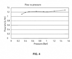
- Figure 4 shows a test result indicating that the present invention is able to function as pressure compensating strip 1, when said strip 1 is operatively connected to a drip irrigation hose 9.
- Different water pressures ranging from 0.3 to 1.5 Bar were used in the test, nevertheless, the resulting water flow rates (and outflow rate) are consistantly ranging between 1.1 to 1.3 liter per hour.
- This experimental result clearly proves that the labyrinth segment according to the present invention, in particular the regulating section that has a first type of profiles 24 and a second type of profiles 25 which function closely together but differently, is able to regulate and fine-tune water flow rate and its response to water pressure in a pressure compensating manner.
- At least one and “one or more” as used herein are interchangeable and relate to at least 1 and include 1, 2, 3, 4, 5, 6, 7, 8, 9 and more.
- irrigation hose is used herein generically to refer to any and all types of irrigation hose, whether seamless or formed with a welded seam, and independent of the structural material, the wall thickness or the degree of flexibility of the hose.
- profiles is used to refer to any barriers or partition walls having any particular shapes, which function to redirect the flow of water of a strip.
- labeling is used to refer to any flow restriction which is implemented as a long thin flow path, and most typically, as a meandering or zigzag flow pattern which allows water to flow throughout its entire length.
- the barriers between sections or legs of the path are referred to as “profiles”, “baffles” or “teeth”, and may be of any shape.
- elastomer is used herein in the description and claims to refer to any elastomeric material with sufficient flexibility to provide variable geometry flow regulation as taught in the context of the various embodiments below, and for which the elastic behavior is roughly repeatable.
- suitable elastomers include, but are not limited to, thermoplastic elastomers (TPE) such as SANTOPRENE ® and thermosetting polymers such as silicone.
- variable geometry flow path which serves to "regulate” the strip's water flow, and to provide a “compensated” strip (drip emitter).
- the terms “regulate” and “compensate” are used to refer to pressure responsive properties which at least partially compensate for variations in flow rate which would otherwise result from variations in the pressure within the irrigation hose.
Landscapes
- Life Sciences & Earth Sciences (AREA)
- Soil Sciences (AREA)
- Engineering & Computer Science (AREA)
- Water Supply & Treatment (AREA)
- Environmental Sciences (AREA)
- Rigid Pipes And Flexible Pipes (AREA)
- Nozzles (AREA)
- Infusion, Injection, And Reservoir Apparatuses (AREA)
Claims (12)
- Une bande (1) à raccorder à un tuyau d'irrigation goutte-à-goutte pour distribuer de l'eau comprenant un segment de labyrinthe répétitif (2, 2'), dans lequel une pluralité de profils (21, 24, 25, 26) sont fournis à une base (15) de la bande (1), ledit segment de labyrinthe (2, 2') comprend:une section d'entrée d'eau (3, 3');une section de régulation (4, 4') disposée en aval de la section d'entrée d'eau, ladite section de régulation étant prévue pour réguler le débit d'eau de la bande (1) en réponse à la pression d'eau dudit tuyau (9), et une section de décharge (5, 5') disposée en aval de la section de régulation (4, 4'), ladite section de décharge étant dotée de moyens de renforcement résistants à la déflexion (26);caractérisé en ce quela section de régulation (4, 4') a deux rails (22) formant des parois latérales de la bande et comprend deux types différents de profils (24, 25) qui sont fournis à la base (15) de la bande (1), les premiers profils (24) étant des cloisons de forme rectangulaire ayant la même hauteur sur toute leur surface supérieure (23) que la surface supérieure des rails (22), les seconds profils (25) étant des cloisons en forme de coin ayant une hauteur qui diminue progressivement vers le centre de la bande (1) par rapport au côté connecté aux rails (22), lesdits premiers et seconds profils (24, 25) étant fournis de manière alternée et régulière ou irrégulière dans toute la section de régulation, de sorte que ladite section de régulation (4, 4') régule simultanément et réagit à la pression d'eau dudit tuyau.
- La bande (1) selon la revendication 1, dans laquelle la section d'entrée d'eau (3, 3') est pourvue d'un moyen de filtration.
- La bande (1) selon la revendication 1 ou la revendication 2, dans laquelle la distance entre les profils (21) dans la section d'entrée est inférieure à la distance entre les profils (24, 25) dans la section de régulation.
- La bande (1) selon la revendication 1, dans laquelle toute la surface supérieure des premiers profils (24) opposée à la base (15) est connectée à une partie intérieure d'un tuyau (9).
- La bande (1) selon la revendication 1, dans laquelle les profils (26) dans la section de décharge (5, 5') sont pourvus de renforts interconnectés (26) pour augmenter la résistance à la déflexion.
- La bande (1) selon la revendication 5, dans laquelle les renforts interconnectés (26) sont fournis à la base de la bande (15).
- La bande (1) selon la revendication 1 et la revendication 5, dans laquelle les renforts interconnectés (26) ont une hauteur inférieure à la surface supérieure (23) du rail (22) de la bande (1).
- Un tuyau d'irrigation goutte-à-goutte à compensation de pression (9) comprenant ladite bande (1) selon l'une quelconque des revendications 1 à 7.
- Le tuyau d'irrigation goutte-à-goutte à compensation de pression (9) selon la revendication 8, dans lequel la bande (1) est fournie à une surface intérieure du tuyau d'irrigation goutte-à-goutte.
- Le tuyau d'irrigation goutte-à-goutte à compensation de pression (9) selon la revendication 8 ou la revendication 9, dans lequel la bande (1) est fabriquée à partir d'un matériau moins rigide que le tuyau d'irrigation goutte-à-goutte à compensation de pression (9).
- Le tuyau d'irrigation goutte-à-goutte à compensation de pression (9) selon l'une quelconque des revendications précédentes 9-10, dans lequel au moins une sortie (12) du tuyau (9) est située à la section de décharge (C, F) de la bande (1).
- Le tuyau d'irrigation goutte-à-goutte à compensation de pression selon la revendication 11, dans lequel la sortie (12) est une sortie à extrémité ouverte ou une fente.
Priority Applications (14)
| Application Number | Priority Date | Filing Date | Title |
|---|---|---|---|
| RS20240951A RS65919B1 (sr) | 2015-08-06 | 2015-08-06 | Crevo za navodnјavanјe kap po kap sa trakom |
| EP15180002.6A EP3127424B1 (fr) | 2015-08-06 | 2015-08-06 | Tuyau d'irrigation au goutte-(a)-goutte à bande |
| PT151800026T PT3127424T (pt) | 2015-08-06 | 2015-08-06 | Uma mangueira de irrigação gota a gota com fita |
| ES15180002T ES2987438T3 (es) | 2015-08-06 | 2015-08-06 | Manguera de riego por goteo con tira |
| MA41877A MA41877A1 (fr) | 2015-08-06 | 2016-08-03 | Tuyau d'irrigation au goutte-à-goutte avec bande |
| PE2018000112A PE20180792A1 (es) | 2015-08-06 | 2016-08-03 | Una manguera de riego por goteo con banda |
| CN201680046229.6A CN107920478B (zh) | 2015-08-06 | 2016-08-03 | 具有带的滴灌喉管 |
| MX2018001299A MX2018001299A (es) | 2015-08-06 | 2016-08-03 | Manguera de irrigacion por goteo con tira. |
| TNP/2018/000025A TN2018000025A1 (en) | 2015-08-06 | 2016-08-03 | A drip irrigation hose with strip |
| PCT/EP2016/068572 WO2017021462A1 (fr) | 2015-08-06 | 2016-08-03 | Tuyau d'irrigation au goutte-à-goutte avec bande |
| US15/750,194 US10716268B2 (en) | 2015-08-06 | 2016-08-03 | Drip irrigation hose with strip |
| RU2018107559A RU2723041C2 (ru) | 2015-08-06 | 2016-08-03 | Шланг для капельного орошения с лентой |
| IL257215A IL257215B (en) | 2015-08-06 | 2016-08-03 | A drip irrigation hose with strip |
| BR112018001071A BR112018001071A2 (pt) | 2015-08-06 | 2016-08-03 | mangueira de irrigação por gotejamento com tira |
Applications Claiming Priority (1)
| Application Number | Priority Date | Filing Date | Title |
|---|---|---|---|
| EP15180002.6A EP3127424B1 (fr) | 2015-08-06 | 2015-08-06 | Tuyau d'irrigation au goutte-(a)-goutte à bande |
Publications (2)
| Publication Number | Publication Date |
|---|---|
| EP3127424A1 EP3127424A1 (fr) | 2017-02-08 |
| EP3127424B1 true EP3127424B1 (fr) | 2024-07-31 |
Family
ID=53783588
Family Applications (1)
| Application Number | Title | Priority Date | Filing Date |
|---|---|---|---|
| EP15180002.6A Active EP3127424B1 (fr) | 2015-08-06 | 2015-08-06 | Tuyau d'irrigation au goutte-(a)-goutte à bande |
Country Status (14)
| Country | Link |
|---|---|
| US (1) | US10716268B2 (fr) |
| EP (1) | EP3127424B1 (fr) |
| CN (1) | CN107920478B (fr) |
| BR (1) | BR112018001071A2 (fr) |
| ES (1) | ES2987438T3 (fr) |
| IL (1) | IL257215B (fr) |
| MA (1) | MA41877A1 (fr) |
| MX (1) | MX2018001299A (fr) |
| PE (1) | PE20180792A1 (fr) |
| PT (1) | PT3127424T (fr) |
| RS (1) | RS65919B1 (fr) |
| RU (1) | RU2723041C2 (fr) |
| TN (1) | TN2018000025A1 (fr) |
| WO (1) | WO2017021462A1 (fr) |
Families Citing this family (9)
| Publication number | Priority date | Publication date | Assignee | Title |
|---|---|---|---|---|
| US10330559B2 (en) | 2014-09-11 | 2019-06-25 | Rain Bird Corporation | Methods and apparatus for checking emitter bonds in an irrigation drip line |
| WO2018140772A1 (fr) | 2017-01-27 | 2018-08-02 | Rain Bird Corporation | Éléments de compensation de pression, émetteurs, canalisation de goutte-à-goutte et procédés associés |
| USD883048S1 (en) | 2017-12-12 | 2020-05-05 | Rain Bird Corporation | Emitter part |
| US11985924B2 (en) | 2018-06-11 | 2024-05-21 | Rain Bird Corporation | Emitter outlet, emitter, drip line and methods relating to same |
| CN112075331B (zh) * | 2019-06-14 | 2023-03-24 | 托罗公司(美国) | 轨道调谐压力响应灌溉灌水器 |
| US11497178B2 (en) | 2019-06-14 | 2022-11-15 | The Toro Company | Drip irrigation emitter with optimized clog resistance |
| US12207599B2 (en) | 2021-10-12 | 2025-01-28 | Rain Bird Corporation | Emitter coupler and irrigation system |
| CN113841590B (zh) * | 2021-10-27 | 2023-03-31 | 三峡大学 | 一种外置贴片式变流道抗堵滴灌带及抗堵滴灌方法 |
| CN117837473B (zh) * | 2024-02-26 | 2026-04-03 | 清华大学 | 迷宫流道及滴灌灌水器 |
Citations (1)
| Publication number | Priority date | Publication date | Assignee | Title |
|---|---|---|---|---|
| US6371390B1 (en) * | 2000-08-21 | 2002-04-16 | Amir Cohen | Drip irrigation hose and method of making same |
Family Cites Families (10)
| Publication number | Priority date | Publication date | Assignee | Title |
|---|---|---|---|---|
| SU471094A1 (ru) * | 1973-08-21 | 1975-05-25 | Украинский Научно-Исследовательский Институт Гидротехники И Мелиорации | Водовыпуск |
| US5400973A (en) * | 1993-07-30 | 1995-03-28 | Cohen; Amir | Pressure responsive regulated flow restrictor useful for drip irrigation |
| US6382530B1 (en) * | 2000-07-10 | 2002-05-07 | Nelson Irrigation Corporation | Pressure compensating drip tape |
| US6886761B2 (en) * | 2000-08-21 | 2005-05-03 | Amir Cohen | Drip irrigation hose and method and apparatus for making same |
| US6736337B2 (en) * | 2002-02-08 | 2004-05-18 | The Toro Company | Pressure compensating drip irrigation hose |
| IL171482A (en) * | 2005-10-19 | 2014-12-31 | Zvi Einav | Drip emitter with an independent non-drain valve |
| US7735758B2 (en) * | 2006-09-18 | 2010-06-15 | Amir Cohen | Drip irrigation hoses of the labyrinth type and flow-control elements for producing such hoses |
| WO2011104722A2 (fr) * | 2010-02-03 | 2011-09-01 | Parixit Amrutbhai Patel | Goutteur d'irrigation goutte-à-goutte non compensé en pression doté d'un dispositif à flux multiples |
| US9485923B2 (en) * | 2012-03-26 | 2016-11-08 | Rain Bird Corporation | Elastomeric emitter and methods relating to same |
| CN203400801U (zh) * | 2013-08-12 | 2014-01-22 | 保定丰霸现代农业设施有限公司 | 压力补偿式耐老化滴灌带 |
-
2015
- 2015-08-06 EP EP15180002.6A patent/EP3127424B1/fr active Active
- 2015-08-06 ES ES15180002T patent/ES2987438T3/es active Active
- 2015-08-06 RS RS20240951A patent/RS65919B1/sr unknown
- 2015-08-06 PT PT151800026T patent/PT3127424T/pt unknown
-
2016
- 2016-08-03 BR BR112018001071A patent/BR112018001071A2/pt not_active Application Discontinuation
- 2016-08-03 MX MX2018001299A patent/MX2018001299A/es unknown
- 2016-08-03 PE PE2018000112A patent/PE20180792A1/es unknown
- 2016-08-03 TN TNP/2018/000025A patent/TN2018000025A1/en unknown
- 2016-08-03 WO PCT/EP2016/068572 patent/WO2017021462A1/fr not_active Ceased
- 2016-08-03 CN CN201680046229.6A patent/CN107920478B/zh active Active
- 2016-08-03 RU RU2018107559A patent/RU2723041C2/ru active
- 2016-08-03 IL IL257215A patent/IL257215B/en unknown
- 2016-08-03 MA MA41877A patent/MA41877A1/fr unknown
- 2016-08-03 US US15/750,194 patent/US10716268B2/en active Active
Patent Citations (1)
| Publication number | Priority date | Publication date | Assignee | Title |
|---|---|---|---|---|
| US6371390B1 (en) * | 2000-08-21 | 2002-04-16 | Amir Cohen | Drip irrigation hose and method of making same |
Also Published As
| Publication number | Publication date |
|---|---|
| PE20180792A1 (es) | 2018-05-08 |
| EP3127424A1 (fr) | 2017-02-08 |
| WO2017021462A1 (fr) | 2017-02-09 |
| ES2987438T3 (es) | 2024-11-14 |
| TN2018000025A1 (en) | 2019-07-08 |
| MX2018001299A (es) | 2018-08-15 |
| IL257215B (en) | 2022-07-01 |
| RS65919B1 (sr) | 2024-10-31 |
| BR112018001071A2 (pt) | 2018-09-11 |
| MA41877A1 (fr) | 2018-07-31 |
| RU2018107559A3 (fr) | 2019-11-14 |
| US10716268B2 (en) | 2020-07-21 |
| IL257215A (en) | 2018-03-29 |
| RU2723041C2 (ru) | 2020-06-08 |
| CN107920478B (zh) | 2021-08-13 |
| PT3127424T (pt) | 2024-09-02 |
| US20180220601A1 (en) | 2018-08-09 |
| RU2018107559A (ru) | 2019-09-09 |
| CN107920478A (zh) | 2018-04-17 |
Similar Documents
| Publication | Publication Date | Title |
|---|---|---|
| EP3127424B1 (fr) | Tuyau d'irrigation au goutte-(a)-goutte à bande | |
| US6736337B2 (en) | Pressure compensating drip irrigation hose | |
| US11185021B2 (en) | Elastomeric emitter and methods relating to same | |
| US9485923B2 (en) | Elastomeric emitter and methods relating to same | |
| US9807948B2 (en) | Drip irrigation tube with metering elements inserted therein | |
| US8663525B2 (en) | Internally pressure compensated non-clogging drip emitter | |
| US8372326B2 (en) | Pressure compensated non-clogging drip emitter | |
| JP6541220B2 (ja) | エミッタおよび点滴灌漑用チューブ | |
| US20230225265A1 (en) | Emitter Outlet, Emitter, Drip Line and Methods Relating To Same | |
| BR112016002731B1 (pt) | emissor elastomérico e métodos relacionados ao mesmo | |
| EP3277077B1 (fr) | Ensemble buse de pulvérisation avec commande de débit de liquide sensible à la pression expansée | |
| EP0538242B1 (fr) | Système d'irrigation goutte à goutte au moyen de passages de courant restrictifs voisins | |
| JP6251186B2 (ja) | 点滴灌漑用ドリッパおよびこれを備えた点滴灌漑装置 | |
| US20080017729A1 (en) | High volume dripping hoses | |
| KR101804680B1 (ko) | 식물재배용 분수 호스 | |
| RU2311758C1 (ru) | Каплеобразующее устройство |
Legal Events
| Date | Code | Title | Description |
|---|---|---|---|
| PUAI | Public reference made under article 153(3) epc to a published international application that has entered the european phase |
Free format text: ORIGINAL CODE: 0009012 |
|
| STAA | Information on the status of an ep patent application or granted ep patent |
Free format text: STATUS: THE APPLICATION HAS BEEN PUBLISHED |
|
| AK | Designated contracting states |
Kind code of ref document: A1 Designated state(s): AL AT BE BG CH CY CZ DE DK EE ES FI FR GB GR HR HU IE IS IT LI LT LU LV MC MK MT NL NO PL PT RO RS SE SI SK SM TR |
|
| AX | Request for extension of the european patent |
Extension state: BA ME |
|
| STAA | Information on the status of an ep patent application or granted ep patent |
Free format text: STATUS: REQUEST FOR EXAMINATION WAS MADE |
|
| 17P | Request for examination filed |
Effective date: 20170629 |
|
| RBV | Designated contracting states (corrected) |
Designated state(s): AL AT BE BG CH CY CZ DE DK EE ES FI FR GB GR HR HU IE IS IT LI LT LU LV MC MK MT NL NO PL PT RO RS SE SI SK SM TR |
|
| STAA | Information on the status of an ep patent application or granted ep patent |
Free format text: STATUS: EXAMINATION IS IN PROGRESS |
|
| 17Q | First examination report despatched |
Effective date: 20210602 |
|
| P01 | Opt-out of the competence of the unified patent court (upc) registered |
Effective date: 20230630 |
|
| GRAP | Despatch of communication of intention to grant a patent |
Free format text: ORIGINAL CODE: EPIDOSNIGR1 |
|
| STAA | Information on the status of an ep patent application or granted ep patent |
Free format text: STATUS: GRANT OF PATENT IS INTENDED |
|
| INTG | Intention to grant announced |
Effective date: 20240327 |
|
| GRAS | Grant fee paid |
Free format text: ORIGINAL CODE: EPIDOSNIGR3 |
|
| GRAA | (expected) grant |
Free format text: ORIGINAL CODE: 0009210 |
|
| STAA | Information on the status of an ep patent application or granted ep patent |
Free format text: STATUS: THE PATENT HAS BEEN GRANTED |
|
| AK | Designated contracting states |
Kind code of ref document: B1 Designated state(s): AL AT BE BG CH CY CZ DE DK EE ES FI FR GB GR HR HU IE IS IT LI LT LU LV MC MK MT NL NO PL PT RO RS SE SI SK SM TR |
|
| REG | Reference to a national code |
Ref country code: CH Ref legal event code: EP Ref country code: GB Ref legal event code: FG4D |
|
| REG | Reference to a national code |
Ref country code: DE Ref legal event code: R096 Ref document number: 602015089364 Country of ref document: DE |
|
| REG | Reference to a national code |
Ref country code: IE Ref legal event code: FG4D |
|
| REG | Reference to a national code |
Ref country code: PT Ref legal event code: SC4A Ref document number: 3127424 Country of ref document: PT Date of ref document: 20240902 Kind code of ref document: T Free format text: AVAILABILITY OF NATIONAL TRANSLATION Effective date: 20240827 |
|
| REG | Reference to a national code |
Ref country code: NL Ref legal event code: FP |
|
| REG | Reference to a national code |
Ref country code: ES Ref legal event code: FG2A Ref document number: 2987438 Country of ref document: ES Kind code of ref document: T3 Effective date: 20241114 |
|
| REG | Reference to a national code |
Ref country code: LT Ref legal event code: MG9D |
|
| REG | Reference to a national code |
Ref country code: GR Ref legal event code: EP Ref document number: 20240402065 Country of ref document: GR Effective date: 20241111 |
|
| REG | Reference to a national code |
Ref country code: AT Ref legal event code: MK05 Ref document number: 1707540 Country of ref document: AT Kind code of ref document: T Effective date: 20240731 |
|
| PG25 | Lapsed in a contracting state [announced via postgrant information from national office to epo] |
Ref country code: NO Free format text: LAPSE BECAUSE OF FAILURE TO SUBMIT A TRANSLATION OF THE DESCRIPTION OR TO PAY THE FEE WITHIN THE PRESCRIBED TIME-LIMIT Effective date: 20241031 |
|
| PG25 | Lapsed in a contracting state [announced via postgrant information from national office to epo] |
Ref country code: FI Free format text: LAPSE BECAUSE OF FAILURE TO SUBMIT A TRANSLATION OF THE DESCRIPTION OR TO PAY THE FEE WITHIN THE PRESCRIBED TIME-LIMIT Effective date: 20240731 Ref country code: PL Free format text: LAPSE BECAUSE OF FAILURE TO SUBMIT A TRANSLATION OF THE DESCRIPTION OR TO PAY THE FEE WITHIN THE PRESCRIBED TIME-LIMIT Effective date: 20240731 |
|
| PG25 | Lapsed in a contracting state [announced via postgrant information from national office to epo] |
Ref country code: LV Free format text: LAPSE BECAUSE OF FAILURE TO SUBMIT A TRANSLATION OF THE DESCRIPTION OR TO PAY THE FEE WITHIN THE PRESCRIBED TIME-LIMIT Effective date: 20240731 |
|
| PG25 | Lapsed in a contracting state [announced via postgrant information from national office to epo] |
Ref country code: AT Free format text: LAPSE BECAUSE OF FAILURE TO SUBMIT A TRANSLATION OF THE DESCRIPTION OR TO PAY THE FEE WITHIN THE PRESCRIBED TIME-LIMIT Effective date: 20240731 Ref country code: IS Free format text: LAPSE BECAUSE OF FAILURE TO SUBMIT A TRANSLATION OF THE DESCRIPTION OR TO PAY THE FEE WITHIN THE PRESCRIBED TIME-LIMIT Effective date: 20241130 |
|
| PG25 | Lapsed in a contracting state [announced via postgrant information from national office to epo] |
Ref country code: HR Free format text: LAPSE BECAUSE OF FAILURE TO SUBMIT A TRANSLATION OF THE DESCRIPTION OR TO PAY THE FEE WITHIN THE PRESCRIBED TIME-LIMIT Effective date: 20240731 |
|
| PG25 | Lapsed in a contracting state [announced via postgrant information from national office to epo] |
Ref country code: PL Free format text: LAPSE BECAUSE OF FAILURE TO SUBMIT A TRANSLATION OF THE DESCRIPTION OR TO PAY THE FEE WITHIN THE PRESCRIBED TIME-LIMIT Effective date: 20240731 Ref country code: NO Free format text: LAPSE BECAUSE OF FAILURE TO SUBMIT A TRANSLATION OF THE DESCRIPTION OR TO PAY THE FEE WITHIN THE PRESCRIBED TIME-LIMIT Effective date: 20241031 Ref country code: LV Free format text: LAPSE BECAUSE OF FAILURE TO SUBMIT A TRANSLATION OF THE DESCRIPTION OR TO PAY THE FEE WITHIN THE PRESCRIBED TIME-LIMIT Effective date: 20240731 Ref country code: IS Free format text: LAPSE BECAUSE OF FAILURE TO SUBMIT A TRANSLATION OF THE DESCRIPTION OR TO PAY THE FEE WITHIN THE PRESCRIBED TIME-LIMIT Effective date: 20241130 Ref country code: HR Free format text: LAPSE BECAUSE OF FAILURE TO SUBMIT A TRANSLATION OF THE DESCRIPTION OR TO PAY THE FEE WITHIN THE PRESCRIBED TIME-LIMIT Effective date: 20240731 Ref country code: FI Free format text: LAPSE BECAUSE OF FAILURE TO SUBMIT A TRANSLATION OF THE DESCRIPTION OR TO PAY THE FEE WITHIN THE PRESCRIBED TIME-LIMIT Effective date: 20240731 Ref country code: AT Free format text: LAPSE BECAUSE OF FAILURE TO SUBMIT A TRANSLATION OF THE DESCRIPTION OR TO PAY THE FEE WITHIN THE PRESCRIBED TIME-LIMIT Effective date: 20240731 |
|
| PG25 | Lapsed in a contracting state [announced via postgrant information from national office to epo] |
Ref country code: DK Free format text: LAPSE BECAUSE OF FAILURE TO SUBMIT A TRANSLATION OF THE DESCRIPTION OR TO PAY THE FEE WITHIN THE PRESCRIBED TIME-LIMIT Effective date: 20240731 Ref country code: SM Free format text: LAPSE BECAUSE OF FAILURE TO SUBMIT A TRANSLATION OF THE DESCRIPTION OR TO PAY THE FEE WITHIN THE PRESCRIBED TIME-LIMIT Effective date: 20240731 |
|
| PG25 | Lapsed in a contracting state [announced via postgrant information from national office to epo] |
Ref country code: LU Free format text: LAPSE BECAUSE OF NON-PAYMENT OF DUE FEES Effective date: 20240806 |
|
| PG25 | Lapsed in a contracting state [announced via postgrant information from national office to epo] |
Ref country code: EE Free format text: LAPSE BECAUSE OF FAILURE TO SUBMIT A TRANSLATION OF THE DESCRIPTION OR TO PAY THE FEE WITHIN THE PRESCRIBED TIME-LIMIT Effective date: 20240731 Ref country code: MC Free format text: LAPSE BECAUSE OF FAILURE TO SUBMIT A TRANSLATION OF THE DESCRIPTION OR TO PAY THE FEE WITHIN THE PRESCRIBED TIME-LIMIT Effective date: 20240731 |
|
| PG25 | Lapsed in a contracting state [announced via postgrant information from national office to epo] |
Ref country code: CZ Free format text: LAPSE BECAUSE OF FAILURE TO SUBMIT A TRANSLATION OF THE DESCRIPTION OR TO PAY THE FEE WITHIN THE PRESCRIBED TIME-LIMIT Effective date: 20240731 |
|
| PG25 | Lapsed in a contracting state [announced via postgrant information from national office to epo] |
Ref country code: SK Free format text: LAPSE BECAUSE OF FAILURE TO SUBMIT A TRANSLATION OF THE DESCRIPTION OR TO PAY THE FEE WITHIN THE PRESCRIBED TIME-LIMIT Effective date: 20240731 |
|
| REG | Reference to a national code |
Ref country code: DE Ref legal event code: R097 Ref document number: 602015089364 Country of ref document: DE |
|
| PLBE | No opposition filed within time limit |
Free format text: ORIGINAL CODE: 0009261 |
|
| STAA | Information on the status of an ep patent application or granted ep patent |
Free format text: STATUS: NO OPPOSITION FILED WITHIN TIME LIMIT |
|
| GBPC | Gb: european patent ceased through non-payment of renewal fee |
Effective date: 20241031 |
|
| REG | Reference to a national code |
Ref country code: BE Ref legal event code: MM Effective date: 20240831 |
|
| 26N | No opposition filed |
Effective date: 20250501 |
|
| PG25 | Lapsed in a contracting state [announced via postgrant information from national office to epo] |
Ref country code: GB Free format text: LAPSE BECAUSE OF NON-PAYMENT OF DUE FEES Effective date: 20241031 |
|
| PG25 | Lapsed in a contracting state [announced via postgrant information from national office to epo] |
Ref country code: BE Free format text: LAPSE BECAUSE OF NON-PAYMENT OF DUE FEES Effective date: 20240831 |
|
| PG25 | Lapsed in a contracting state [announced via postgrant information from national office to epo] |
Ref country code: IE Free format text: LAPSE BECAUSE OF NON-PAYMENT OF DUE FEES Effective date: 20240806 |
|
| PG25 | Lapsed in a contracting state [announced via postgrant information from national office to epo] |
Ref country code: SE Free format text: LAPSE BECAUSE OF FAILURE TO SUBMIT A TRANSLATION OF THE DESCRIPTION OR TO PAY THE FEE WITHIN THE PRESCRIBED TIME-LIMIT Effective date: 20240731 |
|
| PGFP | Annual fee paid to national office [announced via postgrant information from national office to epo] |
Ref country code: NL Payment date: 20250821 Year of fee payment: 11 |
|
| PGFP | Annual fee paid to national office [announced via postgrant information from national office to epo] |
Ref country code: ES Payment date: 20250926 Year of fee payment: 11 Ref country code: PT Payment date: 20250724 Year of fee payment: 11 |
|
| PGFP | Annual fee paid to national office [announced via postgrant information from national office to epo] |
Ref country code: DE Payment date: 20250820 Year of fee payment: 11 |
|
| PGFP | Annual fee paid to national office [announced via postgrant information from national office to epo] |
Ref country code: GR Payment date: 20250822 Year of fee payment: 11 |
|
| PGFP | Annual fee paid to national office [announced via postgrant information from national office to epo] |
Ref country code: IT Payment date: 20250820 Year of fee payment: 11 Ref country code: TR Payment date: 20250729 Year of fee payment: 11 |
|
| PGFP | Annual fee paid to national office [announced via postgrant information from national office to epo] |
Ref country code: BG Payment date: 20250822 Year of fee payment: 11 |
|
| PGFP | Annual fee paid to national office [announced via postgrant information from national office to epo] |
Ref country code: FR Payment date: 20250829 Year of fee payment: 11 |
|
| PGFP | Annual fee paid to national office [announced via postgrant information from national office to epo] |
Ref country code: CH Payment date: 20250901 Year of fee payment: 11 |
|
| PGFP | Annual fee paid to national office [announced via postgrant information from national office to epo] |
Ref country code: RS Payment date: 20250724 Year of fee payment: 11 |
|
| PGFP | Annual fee paid to national office [announced via postgrant information from national office to epo] |
Ref country code: RO Payment date: 20250725 Year of fee payment: 11 |
|
| PGFP | Annual fee paid to national office [announced via postgrant information from national office to epo] |
Ref country code: CY Payment date: 20250724 Year of fee payment: 11 |
|
| PG25 | Lapsed in a contracting state [announced via postgrant information from national office to epo] |
Ref country code: HU Free format text: LAPSE BECAUSE OF FAILURE TO SUBMIT A TRANSLATION OF THE DESCRIPTION OR TO PAY THE FEE WITHIN THE PRESCRIBED TIME-LIMIT; INVALID AB INITIO Effective date: 20150806 |