EP3127461A1 - Procede de fonctionnement d'un appareil d'aspiration pour surfaces dures et appareil d'aspiration pour surfaces dures destine a executer le procede - Google Patents
Procede de fonctionnement d'un appareil d'aspiration pour surfaces dures et appareil d'aspiration pour surfaces dures destine a executer le procede Download PDFInfo
- Publication number
- EP3127461A1 EP3127461A1 EP16185140.7A EP16185140A EP3127461A1 EP 3127461 A1 EP3127461 A1 EP 3127461A1 EP 16185140 A EP16185140 A EP 16185140A EP 3127461 A1 EP3127461 A1 EP 3127461A1
- Authority
- EP
- European Patent Office
- Prior art keywords
- hard surface
- suction unit
- hartflächenabsauggerät
- suction
- hartflächenabsauggeräts
- Prior art date
- Legal status (The legal status is an assumption and is not a legal conclusion. Google has not performed a legal analysis and makes no representation as to the accuracy of the status listed.)
- Granted
Links
Images
Classifications
-
- A—HUMAN NECESSITIES
- A47—FURNITURE; DOMESTIC ARTICLES OR APPLIANCES; COFFEE MILLS; SPICE MILLS; SUCTION CLEANERS IN GENERAL
- A47L—DOMESTIC WASHING OR CLEANING; SUCTION CLEANERS IN GENERAL
- A47L1/00—Cleaning windows
- A47L1/02—Power-driven machines or devices
- A47L1/05—Hand apparatus with built-in electric motors
-
- A—HUMAN NECESSITIES
- A47—FURNITURE; DOMESTIC ARTICLES OR APPLIANCES; COFFEE MILLS; SPICE MILLS; SUCTION CLEANERS IN GENERAL
- A47L—DOMESTIC WASHING OR CLEANING; SUCTION CLEANERS IN GENERAL
- A47L11/00—Machines for cleaning floors, carpets, furniture, walls, or wall coverings
- A47L11/40—Parts or details of machines not provided for in groups A47L11/02 - A47L11/38, or not restricted to one of these groups, e.g. handles, arrangements of switches, skirts, buffers, levers
- A47L11/4011—Regulation of the cleaning machine by electric means; Control systems and remote control systems therefor
-
- A—HUMAN NECESSITIES
- A47—FURNITURE; DOMESTIC ARTICLES OR APPLIANCES; COFFEE MILLS; SPICE MILLS; SUCTION CLEANERS IN GENERAL
- A47L—DOMESTIC WASHING OR CLEANING; SUCTION CLEANERS IN GENERAL
- A47L11/00—Machines for cleaning floors, carpets, furniture, walls, or wall coverings
- A47L11/40—Parts or details of machines not provided for in groups A47L11/02 - A47L11/38, or not restricted to one of these groups, e.g. handles, arrangements of switches, skirts, buffers, levers
- A47L11/4036—Parts or details of the surface treating tools
- A47L11/4044—Vacuuming or pick-up tools; Squeegees
-
- A—HUMAN NECESSITIES
- A47—FURNITURE; DOMESTIC ARTICLES OR APPLIANCES; COFFEE MILLS; SPICE MILLS; SUCTION CLEANERS IN GENERAL
- A47L—DOMESTIC WASHING OR CLEANING; SUCTION CLEANERS IN GENERAL
- A47L5/00—Structural features of suction cleaners
- A47L5/12—Structural features of suction cleaners with power-driven air-pumps or air-compressors, e.g. driven by motor vehicle engine vacuum
- A47L5/22—Structural features of suction cleaners with power-driven air-pumps or air-compressors, e.g. driven by motor vehicle engine vacuum with rotary fans
- A47L5/24—Hand-supported suction cleaners
-
- A—HUMAN NECESSITIES
- A47—FURNITURE; DOMESTIC ARTICLES OR APPLIANCES; COFFEE MILLS; SPICE MILLS; SUCTION CLEANERS IN GENERAL
- A47L—DOMESTIC WASHING OR CLEANING; SUCTION CLEANERS IN GENERAL
- A47L7/00—Suction cleaners adapted for additional purposes; Tables with suction openings for cleaning purposes; Containers for cleaning articles by suction; Suction cleaners adapted to cleaning of brushes; Suction cleaners adapted to taking-up liquids
- A47L7/0004—Suction cleaners adapted to take up liquids, e.g. wet or dry vacuum cleaners
-
- A—HUMAN NECESSITIES
- A47—FURNITURE; DOMESTIC ARTICLES OR APPLIANCES; COFFEE MILLS; SPICE MILLS; SUCTION CLEANERS IN GENERAL
- A47L—DOMESTIC WASHING OR CLEANING; SUCTION CLEANERS IN GENERAL
- A47L9/00—Details or accessories of suction cleaners, e.g. mechanical means for controlling the suction or for effecting pulsating action; Storing devices specially adapted to suction cleaners or parts thereof; Carrying-vehicles specially adapted for suction cleaners
- A47L9/28—Installation of the electric equipment, e.g. adaptation or attachment to the suction cleaner; Controlling suction cleaners by electric means
Definitions
- the invention relates to a method for operating a portable Hartvidabsaug réelles for aspirating a liquid-air mixture of a hard surface, in particular of a window, the Hartvidabsaug réelle a suction nozzle with at least one can be pressed against the hard surface flexible wiper lip, a suction unit and in the flow path between the suction nozzle and the suction unit arranged separating means, which is preferably connected via a liquid outlet with a dirty liquid tank, and wherein the Hartvidabsaug réelle comprises a control device for switching on and off of the suction unit and at least one rechargeable battery for powering the suction unit.
- the invention relates to a portable Hart vomabsaug réelle for performing the above method.
- Portable Hart vomabsaugered with a suction nozzle, a suction unit and a arranged in the flow path between the suction nozzle and the suction device are used for suction of hard surfaces, especially for vacuuming tiled walls or floors, and also for removing a water film from a glass surface, in particular from a window pane or a mirror.
- the suction nozzle has at least one wiper lip, which can be pressed against the hard surface and guided along it.
- the suction nozzle is in flow communication with a suction unit, under the action of which a negative pressure can be generated, so that a liquid-air mixture can be sucked in via the suction nozzle into a housing of the hard surface suction device.
- a separation device In the flow path between the suction nozzle and the suction unit is a separation device, which has at least one separation element.
- the separation element is usually arranged in a separation chamber, which can be acted upon by the suction unit with negative pressure.
- liquid can be separated from the aspirated liquid-air mixture.
- the separated liquid can preferably pass through a liquid outlet opening into a dirty liquid tank of the hard surface suction device, which is used in addition to the suction device and which is preferably arranged outside the flow path between the suction nozzle and the suction unit.
- the power supply of the suction unit takes place with the aid of at least one rechargeable battery and for switching on and off of the suction unit, a control device is used.
- Such Hart vomunabsaugered are from the publications WO 2009/086891 A1 .
- WO 2009/086892 A1 and WO 2009/086893 A1 known and have proven themselves in practice.
- window panes and mirror surfaces can be effectively cleaned with their help.
- the user guides the hard surface suction device along the window pane or mirror surface, pressing the at least one stripper lip against the window pane or the mirror surface.
- a water film located on the window pane or the mirror surface can be effectively sucked off and transferred into the dirty liquid tank. The latter can be emptied if necessary.
- the control of the suction unit is done by means of the control device.
- This usually includes a mechanical on-off switch or a mechanical button that must be operated by the user to start the suction unit.
- the service life of the Hart vomabsaug réelles is limited by the charging capacity of the at least one rechargeable battery and the energy consumption of the suction unit.
- Object of the present invention is to provide a method of the type mentioned and a Hart vomabsaug réelle for performing the method such that the energy consumption of the portable Hartvidabsaug réelles can be reduced.
- the object underlying the invention is achieved in that a resulting from the pressing of the at least one wiper lip against the hard surface mechanical stress of Hartvidabsaug réelles is detected and in the presence of this mechanical stress, the suction unit is turned on automatically.
- the detection of the mechanical stress of the Hartvidabsaug réelles when pressing the at least one wiper lip against the hard surface makes it possible to set the suction unit only when an actual water film is to be sucked from the hard surface.
- the duty cycle of the suction unit can be limited, thereby reducing the energy consumption of the Hartvidabsaug réelles.
- the pressing of the at least one flexible wiper lip against the hard surface leads to a reaction force, with which the Hart vomabsaug réelle, in particular the suction nozzle and / or the separator, are acted upon. It can be provided, for example, that the acting reaction force is detected with the aid of at least one force transducer and then the suction unit is set in motion.
- the suction unit is automatically switched off.
- the mechanical stress of the Hartvidabsaug réelles deleted in such a configuration as soon as the at least one wiper lip is removed from the hard surface. In this case, it is no longer necessary to maintain a suction flow from the suction nozzle to the suction unit, but the suction unit can be turned off.
- the Hartvidabsaug réelle is put into operational readiness in a first process step and then the suction unit is automatically turned on in the presence of a resulting from the pressing of the at least one wiper lip against the hard surface mechanical stress of Hartvidabsaug réelles.
- the Hartvidabsaug réelle is only automatically set in motion when the Hartvidabsaug réelle was previously set to operational readiness. If there is still no operational readiness, pressing the at least one wiper lip against the hard surface does not yet result in the suction unit being switched on. If the operational readiness is terminated before the at least one wiper lip is removed from the hard surface, the suction unit is nevertheless switched off.
- the Hart vomunabsaugêt is manually put into operation.
- a main switch can be used, which can be operated by the user.
- the automatic switching on and off of the suction unit then takes place only after previous manual operation of the main switch.
- the Hartvidabsaug réelle can also be offset by means of a touch sensor, for example by means of a capacitive sensor, ready for operation, with the help of the touch sensor, the manual gripping of the Hartvidabsaug réelles is detected by the user.
- the hard surface aspirator includes a handle on which the user grips the portable hard surface aspirator.
- the touch sensor is preferably arranged on the handle or this immediately adjacent, so that it detects the gripping of the handle by the user and then the Hartroisabsaug réelle can be put into operational readiness. If the user sets aside the hard surface suction device, the touch sensor provides a signal that causes the hard surface suction device to stop operating automatically, in which case the suction unit is switched off.
- the Hartvidabsaug réelle is automatically switched off after a predetermined or predetermined time interval.
- the actual cleaning process in which the at least one wiper lip is pressed against the hard surface, even with large hard surfaces, for example, when cleaning large windows, usually less than a minute, since the user then changes its position relative to the hard surface and in this case the at least one wiper lip away from the hard surface.
- the predetermined time interval lasts less than one minute, preferably only about half a minute. If the time interval has expired, the suction unit is automatically switched off. It can then be switched on again as soon as it is again pressed against the hard surface and thereby again a mechanical stress of the Hartvidabsaug réelles occurs.
- the suction unit is automatically turned off.
- the idea flows in that after completion of a cleaning process, the user usually turns off the hard surface suction device on a floor space, so that it subsequently stops moving in the room. Lies this situation for a given or predeterminable time interval before, the suction unit can then be turned off automatically.
- the mechanical stress of the Hartvidabsaug réelles when pressing the at least one wiper lip against the hard surface can lead to a relative movement between two components of Hartvidabsaug réelles, in particular to a relative movement between two housing parts of Hartvidabsaug réelles.
- the relative movement between the two components resulting from the pressing of the at least one wiper lip against the hard surface is detected and then the suction unit is switched on automatically.
- the Hartvidabsaug réelle may, for example, a first and a second housing part, which are detachably connectable to each other, wherein they are slightly movable in the connected state, that is in the millimeter or Submillimeter Scheme, relative to each other. If the at least one wiper lip is pressed against a hard surface at the beginning of a cleaning process, the two housing parts carry out a slight relative movement with respect to one another. This relative movement can be detected by sensors and serve as a start signal for the suction unit.
- the two relatively movable components in the absence of mechanical stress of the Hartvidabsaug réelles automatically, for example due to the action of a resilient restoring force assume a predetermined position relative to each other, because they perform a renewed relative movement, as soon as the at least one wiper lip is removed from the hard surface, and this relative movement again can serve as a stop signal for the suction unit, so that the suction unit is turned off when the two relatively movable components resume their initial position, they had taken before the start of the cleaning process.
- the relative movement between the two components is conveniently electromechanical, piezoelectric, optical, inductive, and / or capacitive detected.
- An electromechanical detection for example by means of a microswitch or a potentiometer, in particular a Folienpotentiometers, is advantageous.
- an elastic deformation of a component of the Hartvidabsaug réelles is detected in an advantageous embodiment of the method according to the invention resulting from the pressing of the at least one wiper lip and then the suction unit is turned on automatically.
- the at least one wiper lip is designed to be flexible and is subject to an elastic deformation when pressed against the hard surface. This deformation can be detected to start the suction unit.
- the reaction force acting on the hard surface suction device and the component which has elastically deformed when pressing the at least one wiper lip against the hard surface are no longer present.
- the elimination of the deformation can serve as a stop signal for the suction unit, so that it is turned off as soon as the detected deformation of the component is eliminated.
- the elastic deformation of the at least one component of the Hart vomabsaug réelles is conveniently electromechanical, piezoelectric, optical, inductive and / or capacitive detected.
- an electro-mechanical detection for example by means of a strain gauge, is advantageous.
- Such strain gauges are produced inexpensively in very large quantities and are known to those skilled in the art. With their help, a mechanical stress can be detected in a structurally simple way be subjected to the Hard direabsaug réelle when pressing the at least one wiper lip against the hard surface.
- the invention also relates to a portable Hartvidabsaug réelle for performing the method.
- the portable Hartvidabsaug réelle is suitable for aspirating a liquid-air mixture of a hard surface, in particular of a window, and comprises a suction nozzle with at least one pressable to the hard surface flexible wiper lip, a suction unit and a arranged in the flow path between the suction nozzle and the suction unit, the is preferably connected via a liquid outlet with a dirty liquid tank.
- the Hartvidabsaug réelle comprises a control device for switching on and off of the suction unit and at least one rechargeable battery for powering the suction unit.
- the control device comprises a stress detecting device, wherein by means of the stress detecting device resulting from the pressing of the at least one wiper lip against the hard surface resulting mechanical stress of Hartvidabsaug réelles detected and the suction unit is switched on automatically by means of the stress detection device.
- the power consumption of Hart vomabsaugillons can be reduced, because the stress detection device allows the suction unit only turn on when actually a suction flow from the suction nozzle to the suction unit should be present. This is the case when the at least one wiper lip is pressed against the hard surface. As long as the at least one wiper lip still occupies a distance from the hard surface is a suction flow is not necessary and the suction unit is therefore not turned on automatically.
- the suction unit is automatically switched off by eliminating the detected mechanical stress by means of the stress detection device.
- the absence of mechanical stress of the hard surface suction device is detected by the load detection device.
- the mechanical stress is eliminated as soon as the at least one wiper lip is removed from the hard surface. This can, as already explained, serve as a stop signal for the suction unit.
- the suction unit is thus only in operation, as long as the at least one wiper lip is pressed against the hard surface.
- the Hartvidabsaug réelle by the user in operational readiness displaceable and the suction unit is automatically switched on and / or off only in the presence of operational readiness by means of the stress detection device.
- the Hartvidabsaug réelle can be initially put into operational readiness by the user. If the operational readiness is present, the suction unit can then be switched on automatically by means of the load detection device and preferably also automatically switched off again. If the Hartvidabsaug réelle has not been put into operational readiness, an automatic switching on and / or off of the suction unit by means of the stress detection device is not possible. If the operational readiness is terminated by the user, the suction unit is switched off regardless of an output signal of the stress detecting device in each case.
- the Hartvidabsaug réelle has a switching device, in particular a main switch, which is manually operated by the user, wherein the Hartvidabsaug réelle is set in operational readiness by the operation of the switching device.
- the Hartvidabsaug réelle has a touch sensor, in particular a capacitive touch sensor, wherein the touch sensor grasping the Hartvidabsaug réelles detected by the user and thereby the Hartvidabsaug réelle is set into operational readiness.
- the touch sensor is disposed on a handle of the Hart vomabsaug réelles or the handle immediately adjacent.
- the handle is conveniently umgreifbar by the user.
- this includes a timer and the suction unit is automatically switched off after a predetermined or predetermined time interval.
- the Hartvidabsaug réelle in addition to a timer on at least one motion sensor, wherein by means of the at least one motion sensor movement of Hartvidabsaug réelles detected in space and the suction unit after a predetermined or predetermined time interval in which the Hartvidaug réelle was not moved, automatically switched off is.
- a timer and one or more motion sensors it can be ensured by the use of a timer and one or more motion sensors that the suction unit is reliably switched off as soon as the hard surface suction device has not been moved for longer than a predetermined or specifiable time interval. The latter is the case, for example, when the user places the hard surface suction device on a floor space.
- the Hart vomadosaug réelle on a first and a second component which are movable by pressing the at least one wiper lip against the hard surface relative to each other, and the stress detecting device has at least one detecting member on, by means of the detection member, the relative movement of the two components can be detected. If the at least one wiper lip is pressed against the hard surface, then a first component, relative to a second component, is subject to a relative movement, which is detected by at least one detection member in such an embodiment of the hard surface suction device. A corresponding output signal of the detection member can then serve as a start signal for the suction unit, so that this is turned on as soon as the relative movement has been detected.
- the relative movement of the two components can advantageously be detected electromechanically, piezoelectrically, inductively and / or capacitively by means of the at least one detection element.
- an electromechanical detection of the relative movement is advantageous.
- the at least one detection element can be designed, for example, as a microswitch and / or as a potentiometer, in particular in the form of a film potentiometer.
- the at least one detection member is conveniently arranged between the two relatively movable components, so that at least one of the two components can act directly on the detection member, for example on the switching rod of a microswitch.
- the two components are configured as housing parts of the hard surface suction device.
- a first housing part, the separation device and a second housing part receives the suction unit, wherein the first housing part is movable relative to the second housing part.
- the two housing parts are conveniently releasably connectable to each other, and they can perform a relative movement in the millimeter or submillimeter range in the connected state.
- the Hartvidabsaug réelle has at least one by pressing the at least one wiper lip against the hard surface elastically deformable component and that the stress detecting device has at least one deformation sensor, wherein by means of the deformation sensor, the deformation the deformable component is detectable.
- the deformation can be very slight, for example, the deformable component can deform by fractions of a millimeter when the at least one wiper lip is pressed against the hard surface, wherein this slight deformation can be detected by the deformation sensor in a touch or contactless manner.
- the deformation of the deformable component can be detected electromechanically, piezoelectrically, inductively and / or capacitively by means of the at least one deformation sensor.
- the at least one deformation sensor is designed as a strain gauge.
- such strain gauges are available at low cost.
- At least one deformation sensor is integrated in a wiper lip of the hard surface suction device. If the wiper lip is pressed against the hard surface, it is subject to elastic deformation, which can be detected directly by the deformation sensor integrated in the wiper lip.
- the wiper lip can be made, for example, from a rubber-elastic material, wherein the deformation sensor is completely surrounded by the rubber-elastic material.
- At least one deformation sensor is fixed in an advantageous embodiment to a housing part of the Hart vomabsaug réelles, wherein the housing part is subject to the pressing of the at least one wiper lip against the hard surface of an elastic deformation.
- the optionally occurring only in the range of fractions of a millimeter elastic deformation of the housing part can be detected by the deformation sensor attached to it, for example by a strain gauge.
- the output signal of the deformation sensor can then serve as a start signal for the operation of the suction unit.
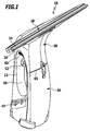
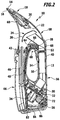
- FIGS. 1 to 3 schematically a first advantageous embodiment of a portable Hartvidaug réelles invention is shown, which is generally occupied by the reference numeral 10.
- a liquid film from a hard surface in particular from a window pane, be sucked. It can do this by the user be held with one hand on a handle 12 and includes a wiper lip 14 and a support lip 16 which can be pressed against the hard surface to be cleaned and guided along this.
- the wiper lip 14 and the support lip 16 form the free end of a suction nozzle 18.
- a suction channel 20 connects, which dips into a deposition chamber 22.
- a separation device 24 with a separation element in the form of a baffle 26 is arranged.
- the suction unit 30 has a suction turbine 32, which is rotated by a motor 34 in rotation.
- a suction flow can be achieved which extends through the suction channel 20, the separation chamber 22 and the vacuum line 28 to the suction unit 30.
- a control device 36 which in addition to the below the motor 34 arranged electrical components has a detail further explained below stress detection device 38 having a detection member in the form of a micro-switch 40.
- the separation chamber 22 is in communication with a dirty liquid tank 44.
- the dirty liquid tank 44 can be filled with the aid of an inlet tube 46 with liquid which is deposited in the separation chamber 22 from the liquid-air mixture, which is sucked under the action of the suction unit 30 via the suction nozzle 18 into the separation chamber 22.
- the separated liquid can pass via the inlet pipe 46 into the dirty liquid tank 44 and the sucked air can be discharged via the vacuum line 28, the suction unit 30 and this downstream in the flow direction air outlet openings 47.
- air in the dirty liquid tank 44 can be discharged to the separation chamber 22 when the level of the liquid tank 44 increases during use of the hard surface suction device 10.
- the Hart vomabsaug réelle 10 has a handle opening 50, which facilitates the grip of the handle 12.
- an electromechanical switch 52 is arranged, which can be actuated by the user when gripping the handle 12.
- the Hartvidaug réelle 10 can be put into operation.
- touch sensor 54 may be arranged, by means of which the gripping of the handle 12 can be detected.
- electrical connection lines is the button 52 and, alternatively, the contact sensor 54 is connected to the motor 34 arranged below the electrical components of the control device 36.
- the Hart vomabsaug réelle 10 further comprises a first component in the form of a housing lower part 56 and a second component in the form of a housing upper part 58.
- the lower housing part 56 receives the suction unit 30 and forms the handle 12, and the upper housing part 58 receives the deposition chamber 22 with the separator 24 ,
- the suction nozzle 18 is attached, which has a in FIG. 2 schematically illustrated upper latching connection 60 is detachably connected to the upper housing part 58.
- the upper housing part 58 has an in FIG. 1 schematically illustrated lower latching connection 62 releasably connected to the lower housing part 56.
- the upper housing part 58 sits with an arcuately curved bottom wall 64 on an arcuately curved top wall 66 of the housing lower part 56. If the upper housing part 58 is connected to the lower housing part 56, it may relative to the lower housing part 56 a slight pivoting movement about a perpendicular to the plane of the FIG. 2 aligned pivot axis Run 58, wherein the bottom wall 64 of the housing upper part 58 slides along the top wall 66 of the housing base 56.
- a microswitch 40 is arranged on the side of the handle 12 facing away from the pushbutton 52. If the wiper lip 14 is pressed against the hard surface to clean a hard surface, then the upper housing part 58 makes a slight relative movement in the form of a pivoting movement about the pivot axis 68 relative to the lower housing part 56. This relative movement is detected by the microswitch 40, which changes its switching position as a result of this relative movement. This change in the switching position has the consequence that the suction unit 30 is turned on after the user has previously set by means of the button 52, the Hart vomabsaug réelle 10 in standby. The activation of the suction unit 30 thus takes place in the in the FIGS.
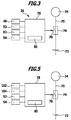
- FIG. 3 illustrated embodiment by detecting the taking place when pressing the wiper lip 14 against a hard surface stress of the Hartvidaug réelles 10, which has a relative movement of the upper housing part 58 relative to the lower housing part 56 result. This is especially true of the in FIG. 3 shown block diagram clearly.
- FIG. 3 shows the motor 34 of the suction unit 30, which is connected via a supply line 70 with a side of the motor 34 arranged rechargeable battery 72.
- a controllable switching unit 74 is connected, the control input 76 is connected to a data processing element 78.
- the data processing element 78 comprises a timer 80 and is connected on the input side to the microswitch 40 and to an acceleration sensor 82 which is positioned with the interposition of a vibration damping element 84 on a printed circuit board 86 arranged below the motor 34 in the housing lower part 56.
- the suction unit 30 can be switched on and off automatically as soon as the user by pressing the button 52, the operational readiness of Hart vomabsaug réelles 10 has made.
- the operational readiness of the hard surface suction device 10 can be established by the user grasping the handle 12, as this can be detected by the touch sensor 54, which is used as an alternative to the button 52 and in FIG. 3 is shown in dashed lines.
- a spring element 69 is arranged, which exerts on the upper housing part 58 a resilient restoring force, under the action of the upper housing part 58 occupies a front pivot position, in which it releases the micro-switch 40. If the wiper lip 14 is pressed during a cleaning process by the user against a hard surface to be cleaned, the upper housing part 58 performs a slight pivoting movement about the pivot axis 68 against the action of the spring element 69, wherein the switch plunger of the microswitch 40 is actuated.
- a corresponding output signal of the microswitch 40 is passed to the data processing element 78 via signal lines, not shown in the drawing to achieve a better overview, which then provides the controllable switching unit 74 with a control signal so that it releases the electrical connection between the battery 72 and the motor 34 ,
- the suction unit 30 is automatically turned on by means of the control device 36 as soon as the Hart vomabsaug réelle 10 experiences a mechanical stress by pressing the wiper lip 14 against the hard surface, which has a relative movement of the upper housing part 58 relative to the lower housing part 56 result.
- a prerequisite for the automatic activation of the suction unit 30 is that previously the operational readiness of the hard surface suction device 10 was established.
- the operation of the suction unit 30 is terminated as soon as the user removes the wiper lip 14 from the hard surface, because then eliminates the mechanical stress of the Hartvidabsaug réelles 10 and the housing upper part 58 takes under the action of the spring element 69 its initial position in which it is the switch plunger of the Microswitch 40 releases.
- a corresponding output signal of the microswitch 40 is then from the data processing element 78, which then interrupts the electrical connection between the battery 72 and the motor 34 by means of the controllable switching unit 74.
- the operation of the suction unit 30 is automatically terminated if the Hart vomabsaug réelle 10 is not moved longer than a predetermined time by the timer 80 in space.
- the movement of the Hartvidabsaug réelles 10 in space is detected by the acceleration sensor 82. If the Hartvidabsaug réelle 10 is not moved, it is subject only to the acceleration of gravity, without any change in acceleration takes place.
- the missing acceleration change is detected by the data processing member 78 and at the end of the predetermined time interval is output by the data processing member 78, a control signal, under the action of the controllable switching unit 74 also interrupts the electrical connection between the battery 72 and the motor 34.
- the operation of the suction unit 30 thus takes place only if, on the one hand, the operational readiness of the Hartvidaug réelles 10 was prepared and on the other the wiper lip 14 is pressed against a hard surface, so that the Hartvidaug réelle 10 is subject to mechanical stress. If the mechanical stress drops away as the user removes the wiper lip 14 from the hard surface, the suction unit 30 is automatically switched off.
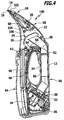
- FIGS. 4 and 5 a second advantageous embodiment of a Hart vomabsaug réelles invention is shown, the total with the reference numeral 100 is occupied.
- the Hart vomabsaug réelle 100 is designed substantially identical to that described above with reference to the FIGS. 1 to 3 described Hart vomabsaug réelle 10.
- For identical components are therefore in the FIGS. 4 and 5 the same reference numerals as in the FIGS. 1 to 3 and with respect to these components, reference is made to the foregoing explanations to avoid repetition.
- the Hart vomabsaug réelle 10 differs from the Hart vomabsaug réelle 100 fact that instead of the microswitch 40, with which a movement of the upper housing part 58 can be detected relative to the housing base 56, a deformation sensor in the form of a strain gauge 102 is used, which is integrated into the flexible wiper lip 14 and detects their elastic deformation during pressing against the hard surface.
- the strain gauge 102 is in electrical connection with the data processing element 78 via a measuring line, not shown in the drawing to achieve a better overview, and provides a measuring signal when the stripper lip 14 is deformed, which is detected by the data processing element 78.
- the upper housing part 58 with the lower housing part 56 is releasably connectable.
- the upper housing part 58 is subject to a slight elastic deformation.
- strain gauges 102 may in the in the FIGS. 4 and 5 embodiment shown, a strain gauge 104 are used, which is fixed below the wiper lip 14 on the inside of the handle 12 remote from the housing wall 106 of the housing upper part 58.
- the strain gauge 104 is in FIG. 4 shown in dashed lines.
- strain gauge 104 can be detected from the pressing of the wiper lip 14 against a hard surface mechanical stress of Hartvidaug réelles 100, and the output of the strain gauge 104 in the same way as the output signal of the strain gauge 102 for automatically switching on and off of the suction unit 30th be used.
- the control device 108 of the hard surface suction device 100 is in FIG. 5 shown in the form of a block diagram.
- An acceleration sensor 82 is omitted in Hartvidabsaug réelle 100.
- the suction unit 30 is the Hartvidabsaug réelle 100 reliably on and off automatically due to the output signals of the strain gauge 102 and / or the strain gauge 104.
- the wiper lip 14 When pressing the wiper lip 14 against the hard surface, the wiper lip 14 as well as the upper housing part subject
- the elastic deformation, which is detected by the strain gauges 102, 104, and the removal of the wiper lip 14 from the hard surface eliminates the elastic deformation, which is also detected by the strain gauges 102, 104.
- the suction unit 30 can thus be switched on and off in a simple manner.
- a prerequisite for the automatic switching on and off of the suction unit 30 is also in Hart vomabsaug réelle 100, which has made the user ready for operation, either by means of the button 52 or through Grasping the handle 12, if the touch sensor 54 is used.
- the timer 80 is used in Hart vomabsaug réelle 100 as additional safety shutdown, with which it is ensured that the suction unit 10 is switched off regardless of a possible mechanical stress of the Hartvidabsaug réelles 100 after a predetermined time interval.
- the suction unit 30 can be automatically switched on and off by the detection of the mechanical stress, which is subject to the Hartvidabsaug réelle 10 or 100 when pressing the wiper lip 14 against a hard surface.
- the battery 72 is thus discharged only during the actual cleaning process, so that the power consumption of the Hartvidabsaug réelle 10 and 100 can be kept low.
- the Hartvidabsaugsammlung 10 and 100 are characterized by easy handling.
Landscapes
- Engineering & Computer Science (AREA)
- Mechanical Engineering (AREA)
- Manipulator (AREA)
- Hooks, Suction Cups, And Attachment By Adhesive Means (AREA)
Applications Claiming Priority (3)
| Application Number | Priority Date | Filing Date | Title |
|---|---|---|---|
| DE102012107997.8A DE102012107997A1 (de) | 2012-08-29 | 2012-08-29 | Verfahren zum Betreiben eines tragbaren Hartflächenabsauggeräts und Hartflächenabsauggerät zur Durchführung des Verfahrens |
| PCT/EP2013/066786 WO2014032945A1 (fr) | 2012-08-29 | 2013-08-12 | Procédé pour faire fonctionner un appareil d'aspiration de surfaces dures portable et appareil d'aspiration de surfaces dures pour mettre en œuvre ce procédé |
| EP13750021.1A EP2890285B1 (fr) | 2012-08-29 | 2013-08-12 | Appareil d'aspiration de surfaces dures portable |
Related Parent Applications (2)
| Application Number | Title | Priority Date | Filing Date |
|---|---|---|---|
| EP13750021.1A Division EP2890285B1 (fr) | 2012-08-29 | 2013-08-12 | Appareil d'aspiration de surfaces dures portable |
| EP13750021.1A Division-Into EP2890285B1 (fr) | 2012-08-29 | 2013-08-12 | Appareil d'aspiration de surfaces dures portable |
Publications (2)
| Publication Number | Publication Date |
|---|---|
| EP3127461A1 true EP3127461A1 (fr) | 2017-02-08 |
| EP3127461B1 EP3127461B1 (fr) | 2019-03-27 |
Family
ID=48986110
Family Applications (2)
| Application Number | Title | Priority Date | Filing Date |
|---|---|---|---|
| EP13750021.1A Active EP2890285B1 (fr) | 2012-08-29 | 2013-08-12 | Appareil d'aspiration de surfaces dures portable |
| EP16185140.7A Active EP3127461B1 (fr) | 2012-08-29 | 2013-08-12 | Procede de fonctionnement d'un appareil d'aspiration pour surfaces dures et appareil d'aspiration pour surfaces dures destine a executer le procede |
Family Applications Before (1)
| Application Number | Title | Priority Date | Filing Date |
|---|---|---|---|
| EP13750021.1A Active EP2890285B1 (fr) | 2012-08-29 | 2013-08-12 | Appareil d'aspiration de surfaces dures portable |
Country Status (4)
| Country | Link |
|---|---|
| EP (2) | EP2890285B1 (fr) |
| CN (1) | CN104602584B (fr) |
| DE (1) | DE102012107997A1 (fr) |
| WO (1) | WO2014032945A1 (fr) |
Families Citing this family (13)
| Publication number | Priority date | Publication date | Assignee | Title |
|---|---|---|---|---|
| DE102012107994A1 (de) * | 2012-08-29 | 2014-03-06 | Alfred Kärcher Gmbh & Co. Kg | Verfahren zum Betreiben eines tragbaren Hartflächenabsauggeräts und Hartflächenabsauggerät zur Durchführung des Verfahrens |
| DE102014110083A1 (de) * | 2014-07-17 | 2016-01-21 | Vorwerk & Co. Interholding Gmbh | Verfahren zum Betrieb eines elektromotorisch angetriebenen Gerätes |
| CN104146654B (zh) * | 2014-08-08 | 2016-05-04 | 南京九致信息科技有限公司 | 一种用于清洗幕墙玻璃的工具 |
| DE102014116978A1 (de) * | 2014-11-20 | 2016-05-25 | Vorwerk & Co. Interholding Gesellschaft mit beschränkter Haftung | Reinigungsgerät mit einem durch einen Motor angetriebenen Gebläse und einem Saugkanal |
| CN104706272A (zh) * | 2015-03-10 | 2015-06-17 | 中山市众智电器有限公司 | 液体抽汲装置及其储液罐组件 |
| WO2016173859A2 (fr) * | 2015-04-30 | 2016-11-03 | Marianne Zippel | Unité d'aspiration et installation d'aspiration comprenant une telle unité d'aspiration |
| CN106308670B (zh) * | 2015-06-17 | 2021-05-14 | 苏州宝时得电动工具有限公司 | 硬表面清洁装置 |
| WO2017108088A1 (fr) * | 2015-12-21 | 2017-06-29 | Alfred Kärcher Gmbh & Co. Kg | Buse d'aspiration pour appareil de nettoyage de surface dure et appareil de nettoyage de surface dure équipé d'une telle buse |
| WO2019143700A1 (fr) | 2018-01-17 | 2019-07-25 | Tti (Macao Commercial Offshore) Limited | Système et procédé permettant de faire fonctionner un système de nettoyage sur la base d'une surface à nettoyer |
| CN112384116B (zh) | 2018-08-27 | 2023-05-05 | 创科地板护理技术有限公司 | 地面清洁器 |
| DE102019211014B4 (de) * | 2019-07-25 | 2024-07-18 | Vorwerk & Co. Interholding Gmbh | Haushaltsreinigungsgerät mit Akkuantrieb |
| US11497371B2 (en) | 2019-12-19 | 2022-11-15 | Techtronic Floor Care Technology Limited | Floor cleaner |
| US11779182B1 (en) | 2022-12-14 | 2023-10-10 | Bissell Inc. | Surface cleaning apparatus |
Citations (5)
| Publication number | Priority date | Publication date | Assignee | Title |
|---|---|---|---|---|
| US20060048800A1 (en) * | 2004-09-09 | 2006-03-09 | Rast Rodger H | Automated building exterior cleaning apparatus |
| WO2009086893A2 (fr) | 2008-01-11 | 2009-07-16 | Alfred Kärcher Gmbh & Co. Kg | Buse d'aspiration |
| WO2009086892A1 (fr) | 2008-01-11 | 2009-07-16 | Alfred Kärcher Gmbh & Co. Kg | Dispositif d'aspiration de surfaces dures |
| WO2009086891A1 (fr) | 2008-01-11 | 2009-07-16 | Alfred Kärcher Gmbh & Co. Kg | Dispositif portable d'aspiration de surfaces dures |
| DE202012101781U1 (de) * | 2012-03-30 | 2012-06-26 | Alfred Kärcher Gmbh & Co. Kg | Hartflächenabsauggerät |
Family Cites Families (6)
| Publication number | Priority date | Publication date | Assignee | Title |
|---|---|---|---|---|
| DE9217416U1 (de) * | 1992-12-19 | 1993-04-08 | Fa. Fedag, Romanshorn | Reinigungswerkzeug mit angetriebener Bürstenwalze |
| DE4427639A1 (de) * | 1993-12-04 | 1995-06-08 | Vorwerk Co Interholding | Mittels eines Elektromotors betriebener Staubsauger |
| DE10038254A1 (de) * | 2000-08-04 | 2002-04-25 | Vorwerk Co Interholding | Verformbare Leiste |
| JP4968189B2 (ja) * | 2008-06-17 | 2012-07-04 | パナソニック株式会社 | 電気掃除機 |
| CN102113855A (zh) * | 2010-01-04 | 2011-07-06 | 乐金电子(天津)电器有限公司 | 具有尖吸嘴功能的吸尘器吸头 |
| DE102011050697A1 (de) * | 2011-05-27 | 2012-11-29 | Leifheit Ag | Flüssigkeitssaugvorrichtung zum Abziehen und Aufsaugen von Flüssigkeiten |
-
2012
- 2012-08-29 DE DE102012107997.8A patent/DE102012107997A1/de not_active Withdrawn
-
2013
- 2013-08-12 EP EP13750021.1A patent/EP2890285B1/fr active Active
- 2013-08-12 CN CN201380044596.9A patent/CN104602584B/zh active Active
- 2013-08-12 EP EP16185140.7A patent/EP3127461B1/fr active Active
- 2013-08-12 WO PCT/EP2013/066786 patent/WO2014032945A1/fr not_active Ceased
Patent Citations (5)
| Publication number | Priority date | Publication date | Assignee | Title |
|---|---|---|---|---|
| US20060048800A1 (en) * | 2004-09-09 | 2006-03-09 | Rast Rodger H | Automated building exterior cleaning apparatus |
| WO2009086893A2 (fr) | 2008-01-11 | 2009-07-16 | Alfred Kärcher Gmbh & Co. Kg | Buse d'aspiration |
| WO2009086892A1 (fr) | 2008-01-11 | 2009-07-16 | Alfred Kärcher Gmbh & Co. Kg | Dispositif d'aspiration de surfaces dures |
| WO2009086891A1 (fr) | 2008-01-11 | 2009-07-16 | Alfred Kärcher Gmbh & Co. Kg | Dispositif portable d'aspiration de surfaces dures |
| DE202012101781U1 (de) * | 2012-03-30 | 2012-06-26 | Alfred Kärcher Gmbh & Co. Kg | Hartflächenabsauggerät |
Also Published As
| Publication number | Publication date |
|---|---|
| WO2014032945A1 (fr) | 2014-03-06 |
| EP3127461B1 (fr) | 2019-03-27 |
| DE102012107997A1 (de) | 2014-03-06 |
| EP2890285B1 (fr) | 2016-10-05 |
| CN104602584B (zh) | 2017-08-29 |
| CN104602584A (zh) | 2015-05-06 |
| EP2890285A1 (fr) | 2015-07-08 |
Similar Documents
| Publication | Publication Date | Title |
|---|---|---|
| EP3127461B1 (fr) | Procede de fonctionnement d'un appareil d'aspiration pour surfaces dures et appareil d'aspiration pour surfaces dures destine a executer le procede | |
| EP2890284B1 (fr) | Appareil d'aspiration de surfaces dures portable | |
| EP3795055B1 (fr) | Machine de nettoyage des sols | |
| EP1519673B8 (fr) | Procede pour faire fonctionner un systeme de nettoyage de sol, et systeme de nettoyage de sol fonctionnant selon ce procede | |
| EP0822774B1 (fr) | Embout d'aspirateur pour le nettoyage humide de surfaces | |
| WO2014032712A1 (fr) | Système d'aspiration de surfaces équipé d'un dispositif d'allonge | |
| EP2830473A1 (fr) | Appareil d'aspiration pour surfaces dures | |
| EP3727120A1 (fr) | Nettoyage de filtre efficace | |
| EP2974639B1 (fr) | Procede de fonctionnement d'un appareil a moteur electrique | |
| DE102010038095A1 (de) | Entleerungsstation für einen akkumulatorbetriebenen Elektrostaubsauger | |
| EP3581082B1 (fr) | Robot d'aspiration et procédé de commande d'un robot d'aspiration | |
| EP2644076B1 (fr) | Aspirateur | |
| DE102013108905A1 (de) | Zur Feuchtreinigung ausgebildetes Reinigungsgerät | |
| DE102014116978A1 (de) | Reinigungsgerät mit einem durch einen Motor angetriebenen Gebläse und einem Saugkanal | |
| EP2505115B1 (fr) | Aspirateur et procédé destiné au fonctionnement en fonction de la durée de fonctionnement d'un aspirateur | |
| WO2009090109A1 (fr) | Aspirateur à détection du niveau de remplissage du récipient à poussière et procédé de fonctionnement d'un aspirateur | |
| DE102019102382A1 (de) | Sauggutsammelstation und System aus einer Sauggutsammelstation und einem Saugreinigungsgerät | |
| EP3437535B1 (fr) | Aspirateur | |
| DE3120250C2 (de) | Handgerät zur Entstaubung | |
| DE19905444C2 (de) | Vorrichtung zum Saugen | |
| EP3692881B1 (fr) | Aspirateur guidé à la main | |
| EP4154782B1 (fr) | Aspirateur et sac à poussière | |
| DE102024109193A1 (de) | Reinigungsroboter zur autonomen Reinigung einer Bodenfläche | |
| DE102021113323A1 (de) | Tragbares Reinigungsgerät | |
| DE102021109222A1 (de) | Staubsauger |
Legal Events
| Date | Code | Title | Description |
|---|---|---|---|
| PUAI | Public reference made under article 153(3) epc to a published international application that has entered the european phase |
Free format text: ORIGINAL CODE: 0009012 |
|
| STAA | Information on the status of an ep patent application or granted ep patent |
Free format text: STATUS: THE APPLICATION HAS BEEN PUBLISHED |
|
| AC | Divisional application: reference to earlier application |
Ref document number: 2890285 Country of ref document: EP Kind code of ref document: P |
|
| AK | Designated contracting states |
Kind code of ref document: A1 Designated state(s): AL AT BE BG CH CY CZ DE DK EE ES FI FR GB GR HR HU IE IS IT LI LT LU LV MC MK MT NL NO PL PT RO RS SE SI SK SM TR |
|
| STAA | Information on the status of an ep patent application or granted ep patent |
Free format text: STATUS: REQUEST FOR EXAMINATION WAS MADE |
|
| 17P | Request for examination filed |
Effective date: 20170804 |
|
| RBV | Designated contracting states (corrected) |
Designated state(s): AL AT BE BG CH CY CZ DE DK EE ES FI FR GB GR HR HU IE IS IT LI LT LU LV MC MK MT NL NO PL PT RO RS SE SI SK SM TR |
|
| GRAP | Despatch of communication of intention to grant a patent |
Free format text: ORIGINAL CODE: EPIDOSNIGR1 |
|
| STAA | Information on the status of an ep patent application or granted ep patent |
Free format text: STATUS: GRANT OF PATENT IS INTENDED |
|
| RIC1 | Information provided on ipc code assigned before grant |
Ipc: A47L 1/05 20060101ALI20180614BHEP Ipc: A47L 5/24 20060101AFI20180614BHEP Ipc: A47L 11/40 20060101ALI20180614BHEP Ipc: A47L 7/00 20060101ALI20180614BHEP Ipc: A47L 9/28 20060101ALI20180614BHEP |
|
| INTG | Intention to grant announced |
Effective date: 20180704 |
|
| RAP1 | Party data changed (applicant data changed or rights of an application transferred) |
Owner name: ALFRED KAERCHER SE & CO. KG |
|
| GRAJ | Information related to disapproval of communication of intention to grant by the applicant or resumption of examination proceedings by the epo deleted |
Free format text: ORIGINAL CODE: EPIDOSDIGR1 |
|
| STAA | Information on the status of an ep patent application or granted ep patent |
Free format text: STATUS: REQUEST FOR EXAMINATION WAS MADE |
|
| RBV | Designated contracting states (corrected) |
Designated state(s): AL AT BE BG CH CY CZ DK EE ES FI FR GB GR HR HU IE IS IT LI LT LU LV MC MK MT NL NO PL PT RO RS SE SI SK SM TR |
|
| REG | Reference to a national code |
Ref country code: DE Ref legal event code: R108 |
|
| GRAP | Despatch of communication of intention to grant a patent |
Free format text: ORIGINAL CODE: EPIDOSNIGR1 |
|
| STAA | Information on the status of an ep patent application or granted ep patent |
Free format text: STATUS: GRANT OF PATENT IS INTENDED |
|
| INTC | Intention to grant announced (deleted) | ||
| INTG | Intention to grant announced |
Effective date: 20181119 |
|
| GRAS | Grant fee paid |
Free format text: ORIGINAL CODE: EPIDOSNIGR3 |
|
| GRAA | (expected) grant |
Free format text: ORIGINAL CODE: 0009210 |
|
| STAA | Information on the status of an ep patent application or granted ep patent |
Free format text: STATUS: THE PATENT HAS BEEN GRANTED |
|
| AC | Divisional application: reference to earlier application |
Ref document number: 2890285 Country of ref document: EP Kind code of ref document: P |
|
| AK | Designated contracting states |
Kind code of ref document: B1 Designated state(s): AL AT BE BG CH CY CZ DK EE ES FI FR GB GR HR HU IE IS IT LI LT LU LV MC MK MT NL NO PL PT RO RS SE SI SK SM TR |
|
| REG | Reference to a national code |
Ref country code: GB Ref legal event code: FG4D Free format text: NOT ENGLISH |
|
| REG | Reference to a national code |
Ref country code: CH Ref legal event code: EP |
|
| REG | Reference to a national code |
Ref country code: AT Ref legal event code: REF Ref document number: 1111993 Country of ref document: AT Kind code of ref document: T Effective date: 20190415 |
|
| REG | Reference to a national code |
Ref country code: IE Ref legal event code: FG4D Free format text: LANGUAGE OF EP DOCUMENT: GERMAN |
|
| PG25 | Lapsed in a contracting state [announced via postgrant information from national office to epo] |
Ref country code: LT Free format text: LAPSE BECAUSE OF FAILURE TO SUBMIT A TRANSLATION OF THE DESCRIPTION OR TO PAY THE FEE WITHIN THE PRESCRIBED TIME-LIMIT Effective date: 20190327 Ref country code: SE Free format text: LAPSE BECAUSE OF FAILURE TO SUBMIT A TRANSLATION OF THE DESCRIPTION OR TO PAY THE FEE WITHIN THE PRESCRIBED TIME-LIMIT Effective date: 20190327 Ref country code: FI Free format text: LAPSE BECAUSE OF FAILURE TO SUBMIT A TRANSLATION OF THE DESCRIPTION OR TO PAY THE FEE WITHIN THE PRESCRIBED TIME-LIMIT Effective date: 20190327 Ref country code: NO Free format text: LAPSE BECAUSE OF FAILURE TO SUBMIT A TRANSLATION OF THE DESCRIPTION OR TO PAY THE FEE WITHIN THE PRESCRIBED TIME-LIMIT Effective date: 20190627 |
|
| REG | Reference to a national code |
Ref country code: NL Ref legal event code: MP Effective date: 20190327 |
|
| PG25 | Lapsed in a contracting state [announced via postgrant information from national office to epo] |
Ref country code: LV Free format text: LAPSE BECAUSE OF FAILURE TO SUBMIT A TRANSLATION OF THE DESCRIPTION OR TO PAY THE FEE WITHIN THE PRESCRIBED TIME-LIMIT Effective date: 20190327 Ref country code: GR Free format text: LAPSE BECAUSE OF FAILURE TO SUBMIT A TRANSLATION OF THE DESCRIPTION OR TO PAY THE FEE WITHIN THE PRESCRIBED TIME-LIMIT Effective date: 20190628 Ref country code: HR Free format text: LAPSE BECAUSE OF FAILURE TO SUBMIT A TRANSLATION OF THE DESCRIPTION OR TO PAY THE FEE WITHIN THE PRESCRIBED TIME-LIMIT Effective date: 20190327 Ref country code: RS Free format text: LAPSE BECAUSE OF FAILURE TO SUBMIT A TRANSLATION OF THE DESCRIPTION OR TO PAY THE FEE WITHIN THE PRESCRIBED TIME-LIMIT Effective date: 20190327 Ref country code: NL Free format text: LAPSE BECAUSE OF FAILURE TO SUBMIT A TRANSLATION OF THE DESCRIPTION OR TO PAY THE FEE WITHIN THE PRESCRIBED TIME-LIMIT Effective date: 20190327 Ref country code: BG Free format text: LAPSE BECAUSE OF FAILURE TO SUBMIT A TRANSLATION OF THE DESCRIPTION OR TO PAY THE FEE WITHIN THE PRESCRIBED TIME-LIMIT Effective date: 20190627 |
|
| PG25 | Lapsed in a contracting state [announced via postgrant information from national office to epo] |
Ref country code: AL Free format text: LAPSE BECAUSE OF FAILURE TO SUBMIT A TRANSLATION OF THE DESCRIPTION OR TO PAY THE FEE WITHIN THE PRESCRIBED TIME-LIMIT Effective date: 20190327 Ref country code: ES Free format text: LAPSE BECAUSE OF FAILURE TO SUBMIT A TRANSLATION OF THE DESCRIPTION OR TO PAY THE FEE WITHIN THE PRESCRIBED TIME-LIMIT Effective date: 20190327 Ref country code: CZ Free format text: LAPSE BECAUSE OF FAILURE TO SUBMIT A TRANSLATION OF THE DESCRIPTION OR TO PAY THE FEE WITHIN THE PRESCRIBED TIME-LIMIT Effective date: 20190327 Ref country code: RO Free format text: LAPSE BECAUSE OF FAILURE TO SUBMIT A TRANSLATION OF THE DESCRIPTION OR TO PAY THE FEE WITHIN THE PRESCRIBED TIME-LIMIT Effective date: 20190327 Ref country code: EE Free format text: LAPSE BECAUSE OF FAILURE TO SUBMIT A TRANSLATION OF THE DESCRIPTION OR TO PAY THE FEE WITHIN THE PRESCRIBED TIME-LIMIT Effective date: 20190327 Ref country code: SK Free format text: LAPSE BECAUSE OF FAILURE TO SUBMIT A TRANSLATION OF THE DESCRIPTION OR TO PAY THE FEE WITHIN THE PRESCRIBED TIME-LIMIT Effective date: 20190327 Ref country code: PT Free format text: LAPSE BECAUSE OF FAILURE TO SUBMIT A TRANSLATION OF THE DESCRIPTION OR TO PAY THE FEE WITHIN THE PRESCRIBED TIME-LIMIT Effective date: 20190727 |
|
| PG25 | Lapsed in a contracting state [announced via postgrant information from national office to epo] |
Ref country code: PL Free format text: LAPSE BECAUSE OF FAILURE TO SUBMIT A TRANSLATION OF THE DESCRIPTION OR TO PAY THE FEE WITHIN THE PRESCRIBED TIME-LIMIT Effective date: 20190327 Ref country code: SM Free format text: LAPSE BECAUSE OF FAILURE TO SUBMIT A TRANSLATION OF THE DESCRIPTION OR TO PAY THE FEE WITHIN THE PRESCRIBED TIME-LIMIT Effective date: 20190327 |
|
| PG25 | Lapsed in a contracting state [announced via postgrant information from national office to epo] |
Ref country code: IS Free format text: LAPSE BECAUSE OF FAILURE TO SUBMIT A TRANSLATION OF THE DESCRIPTION OR TO PAY THE FEE WITHIN THE PRESCRIBED TIME-LIMIT Effective date: 20190727 |
|
| PG25 | Lapsed in a contracting state [announced via postgrant information from national office to epo] |
Ref country code: DK Free format text: LAPSE BECAUSE OF FAILURE TO SUBMIT A TRANSLATION OF THE DESCRIPTION OR TO PAY THE FEE WITHIN THE PRESCRIBED TIME-LIMIT Effective date: 20190327 |
|
| PLBE | No opposition filed within time limit |
Free format text: ORIGINAL CODE: 0009261 |
|
| STAA | Information on the status of an ep patent application or granted ep patent |
Free format text: STATUS: NO OPPOSITION FILED WITHIN TIME LIMIT |
|
| PG25 | Lapsed in a contracting state [announced via postgrant information from national office to epo] |
Ref country code: SI Free format text: LAPSE BECAUSE OF FAILURE TO SUBMIT A TRANSLATION OF THE DESCRIPTION OR TO PAY THE FEE WITHIN THE PRESCRIBED TIME-LIMIT Effective date: 20190327 |
|
| 26N | No opposition filed |
Effective date: 20200103 |
|
| PG25 | Lapsed in a contracting state [announced via postgrant information from national office to epo] |
Ref country code: TR Free format text: LAPSE BECAUSE OF FAILURE TO SUBMIT A TRANSLATION OF THE DESCRIPTION OR TO PAY THE FEE WITHIN THE PRESCRIBED TIME-LIMIT Effective date: 20190327 |
|
| GBPC | Gb: european patent ceased through non-payment of renewal fee |
Effective date: 20190812 |
|
| PG25 | Lapsed in a contracting state [announced via postgrant information from national office to epo] |
Ref country code: MC Free format text: LAPSE BECAUSE OF FAILURE TO SUBMIT A TRANSLATION OF THE DESCRIPTION OR TO PAY THE FEE WITHIN THE PRESCRIBED TIME-LIMIT Effective date: 20190327 Ref country code: CH Free format text: LAPSE BECAUSE OF NON-PAYMENT OF DUE FEES Effective date: 20190831 Ref country code: LI Free format text: LAPSE BECAUSE OF NON-PAYMENT OF DUE FEES Effective date: 20190831 Ref country code: LU Free format text: LAPSE BECAUSE OF NON-PAYMENT OF DUE FEES Effective date: 20190812 |
|
| REG | Reference to a national code |
Ref country code: BE Ref legal event code: MM Effective date: 20190831 |
|
| PG25 | Lapsed in a contracting state [announced via postgrant information from national office to epo] |
Ref country code: FR Free format text: LAPSE BECAUSE OF NON-PAYMENT OF DUE FEES Effective date: 20190831 Ref country code: IE Free format text: LAPSE BECAUSE OF NON-PAYMENT OF DUE FEES Effective date: 20190812 |
|
| PG25 | Lapsed in a contracting state [announced via postgrant information from national office to epo] |
Ref country code: BE Free format text: LAPSE BECAUSE OF NON-PAYMENT OF DUE FEES Effective date: 20190831 Ref country code: GB Free format text: LAPSE BECAUSE OF NON-PAYMENT OF DUE FEES Effective date: 20190812 |
|
| REG | Reference to a national code |
Ref country code: AT Ref legal event code: MM01 Ref document number: 1111993 Country of ref document: AT Kind code of ref document: T Effective date: 20190812 |
|
| PG25 | Lapsed in a contracting state [announced via postgrant information from national office to epo] |
Ref country code: AT Free format text: LAPSE BECAUSE OF NON-PAYMENT OF DUE FEES Effective date: 20190812 |
|
| PG25 | Lapsed in a contracting state [announced via postgrant information from national office to epo] |
Ref country code: CY Free format text: LAPSE BECAUSE OF FAILURE TO SUBMIT A TRANSLATION OF THE DESCRIPTION OR TO PAY THE FEE WITHIN THE PRESCRIBED TIME-LIMIT Effective date: 20190327 |
|
| PG25 | Lapsed in a contracting state [announced via postgrant information from national office to epo] |
Ref country code: MT Free format text: LAPSE BECAUSE OF FAILURE TO SUBMIT A TRANSLATION OF THE DESCRIPTION OR TO PAY THE FEE WITHIN THE PRESCRIBED TIME-LIMIT Effective date: 20190327 Ref country code: HU Free format text: LAPSE BECAUSE OF FAILURE TO SUBMIT A TRANSLATION OF THE DESCRIPTION OR TO PAY THE FEE WITHIN THE PRESCRIBED TIME-LIMIT; INVALID AB INITIO Effective date: 20130812 |
|
| PG25 | Lapsed in a contracting state [announced via postgrant information from national office to epo] |
Ref country code: MK Free format text: LAPSE BECAUSE OF FAILURE TO SUBMIT A TRANSLATION OF THE DESCRIPTION OR TO PAY THE FEE WITHIN THE PRESCRIBED TIME-LIMIT Effective date: 20190327 |
|
| P01 | Opt-out of the competence of the unified patent court (upc) registered |
Effective date: 20230521 |
|
| PGFP | Annual fee paid to national office [announced via postgrant information from national office to epo] |
Ref country code: IT Payment date: 20250722 Year of fee payment: 13 |