EP3127486B1 - Verfahren und vorrichtung zur automatischen identifikation eines messelements und ultraschallbildgebungsvorrichtung - Google Patents
Verfahren und vorrichtung zur automatischen identifikation eines messelements und ultraschallbildgebungsvorrichtung Download PDFInfo
- Publication number
- EP3127486B1 EP3127486B1 EP14885962.2A EP14885962A EP3127486B1 EP 3127486 B1 EP3127486 B1 EP 3127486B1 EP 14885962 A EP14885962 A EP 14885962A EP 3127486 B1 EP3127486 B1 EP 3127486B1
- Authority
- EP
- European Patent Office
- Prior art keywords
- section image
- specified section
- image
- characteristic
- training sample
- Prior art date
- Legal status (The legal status is an assumption and is not a legal conclusion. Google has not performed a legal analysis and makes no representation as to the accuracy of the status listed.)
- Active
Links
Images

Classifications
-
- A—HUMAN NECESSITIES
- A61—MEDICAL OR VETERINARY SCIENCE; HYGIENE
- A61B—DIAGNOSIS; SURGERY; IDENTIFICATION
- A61B5/00—Measuring for diagnostic purposes; Identification of persons
- A61B5/103—Measuring devices for testing the shape, pattern, colour, size or movement of the body or parts thereof, for diagnostic purposes
- A61B5/107—Measuring physical dimensions, e.g. size of the entire body or parts thereof
- A61B5/1075—Measuring physical dimensions, e.g. size of the entire body or parts thereof for measuring dimensions by non-invasive methods, e.g. for determining thickness of tissue layer
-
- A—HUMAN NECESSITIES
- A61—MEDICAL OR VETERINARY SCIENCE; HYGIENE
- A61B—DIAGNOSIS; SURGERY; IDENTIFICATION
- A61B5/00—Measuring for diagnostic purposes; Identification of persons
- A61B5/72—Signal processing specially adapted for physiological signals or for diagnostic purposes
- A61B5/7235—Details of waveform analysis
- A61B5/7264—Classification of physiological signals or data, e.g. using neural networks, statistical classifiers, expert systems or fuzzy systems
- A61B5/7267—Classification of physiological signals or data, e.g. using neural networks, statistical classifiers, expert systems or fuzzy systems involving training the classification device
-
- A—HUMAN NECESSITIES
- A61—MEDICAL OR VETERINARY SCIENCE; HYGIENE
- A61B—DIAGNOSIS; SURGERY; IDENTIFICATION
- A61B8/00—Diagnosis using ultrasonic, sonic or infrasonic waves
- A61B8/08—Clinical applications
-
- A—HUMAN NECESSITIES
- A61—MEDICAL OR VETERINARY SCIENCE; HYGIENE
- A61B—DIAGNOSIS; SURGERY; IDENTIFICATION
- A61B8/00—Diagnosis using ultrasonic, sonic or infrasonic waves
- A61B8/08—Clinical applications
- A61B8/0866—Clinical applications involving foetal diagnosis; pre-natal or peri-natal diagnosis of the baby
-
- A—HUMAN NECESSITIES
- A61—MEDICAL OR VETERINARY SCIENCE; HYGIENE
- A61B—DIAGNOSIS; SURGERY; IDENTIFICATION
- A61B8/00—Diagnosis using ultrasonic, sonic or infrasonic waves
- A61B8/08—Clinical applications
- A61B8/0875—Clinical applications for diagnosis of bone
-
- A—HUMAN NECESSITIES
- A61—MEDICAL OR VETERINARY SCIENCE; HYGIENE
- A61B—DIAGNOSIS; SURGERY; IDENTIFICATION
- A61B8/00—Diagnosis using ultrasonic, sonic or infrasonic waves
- A61B8/44—Constructional features of the ultrasonic, sonic or infrasonic diagnostic device
- A61B8/4444—Constructional features of the ultrasonic, sonic or infrasonic diagnostic device related to the probe
- A61B8/4461—Features of the scanning mechanism, e.g. for moving the transducer within the housing of the probe
-
- A—HUMAN NECESSITIES
- A61—MEDICAL OR VETERINARY SCIENCE; HYGIENE
- A61B—DIAGNOSIS; SURGERY; IDENTIFICATION
- A61B8/00—Diagnosis using ultrasonic, sonic or infrasonic waves
- A61B8/46—Ultrasonic, sonic or infrasonic diagnostic devices with special arrangements for interfacing with the operator or the patient
- A61B8/467—Ultrasonic, sonic or infrasonic diagnostic devices with special arrangements for interfacing with the operator or the patient characterised by special input means
- A61B8/469—Ultrasonic, sonic or infrasonic diagnostic devices with special arrangements for interfacing with the operator or the patient characterised by special input means for selection of a region of interest
-
- A—HUMAN NECESSITIES
- A61—MEDICAL OR VETERINARY SCIENCE; HYGIENE
- A61B—DIAGNOSIS; SURGERY; IDENTIFICATION
- A61B8/00—Diagnosis using ultrasonic, sonic or infrasonic waves
- A61B8/52—Devices using data or image processing specially adapted for diagnosis using ultrasonic, sonic or infrasonic waves
- A61B8/5215—Devices using data or image processing specially adapted for diagnosis using ultrasonic, sonic or infrasonic waves involving processing of medical diagnostic data
- A61B8/5223—Devices using data or image processing specially adapted for diagnosis using ultrasonic, sonic or infrasonic waves involving processing of medical diagnostic data for extracting a diagnostic or physiological parameter from medical diagnostic data
-
- G—PHYSICS
- G06—COMPUTING OR CALCULATING; COUNTING
- G06T—IMAGE DATA PROCESSING OR GENERATION, IN GENERAL
- G06T7/00—Image analysis
- G06T7/0002—Inspection of images, e.g. flaw detection
- G06T7/0012—Biomedical image inspection
-
- G—PHYSICS
- G06—COMPUTING OR CALCULATING; COUNTING
- G06T—IMAGE DATA PROCESSING OR GENERATION, IN GENERAL
- G06T7/00—Image analysis
- G06T7/60—Analysis of geometric attributes
-
- G—PHYSICS
- G16—INFORMATION AND COMMUNICATION TECHNOLOGY [ICT] SPECIALLY ADAPTED FOR SPECIFIC APPLICATION FIELDS
- G16H—HEALTHCARE INFORMATICS, i.e. INFORMATION AND COMMUNICATION TECHNOLOGY [ICT] SPECIALLY ADAPTED FOR THE HANDLING OR PROCESSING OF MEDICAL OR HEALTHCARE DATA
- G16H50/00—ICT specially adapted for medical diagnosis, medical simulation or medical data mining; ICT specially adapted for detecting, monitoring or modelling epidemics or pandemics
- G16H50/30—ICT specially adapted for medical diagnosis, medical simulation or medical data mining; ICT specially adapted for detecting, monitoring or modelling epidemics or pandemics for calculating health indices; for individual health risk assessment
Definitions
- the present disclosure relates to medical equipment, in particular to an ultrasound imaging apparatus and a method and device for automatic identification of measurement item thereof.
- Ultrasound imaging apparatus are generally used by a doctor to inspect tissues inside a human body.
- the doctor can place an ultrasound probe onto the surface of the skin corresponding to a tissue to obtain ultrasound images of the tissue. Due to its characteristics of safety, convenience, non-invasion and low cost, etc, the ultrasound imaging has become a main assisting means for diagnosis.
- the doctor In order to obtain measurements of an object of interest, the doctor needs to perform many measuring operations during the ultrasound examination. Since there are generally a plurality of measurement items which need to be measured for a tissue being examined in one measuring mode while the measuring is a process in which the user needs to constantly interact with the apparatus, the user needs to constantly select the measurement item and then move a trackball to perform the measuring, which is time-consuming.
- the common measurement items include the size of liver, gallbladder, spleen and kidney, etc.
- head circumference (HC), biparietal diameter (BPD), abdominal circumference (AC) and femur length (FL) are necessary measurement items for each examination.
- the doctor may obtain a standard section image, and then press a button for measuring, by which a measurement menu will be displayed by the apparatus. Then, the doctor may move the trackball to select a desired measurement item in the menu, and then the measuring of the selected measurement item can be performed. For example, in an obstetric examination, after obtaining a corresponding standard section image, the doctor firstly presses the button for measuring, by which the measurement menu will be displayed and a measuring state will be entered, and then moves the trackball to select a desired measurement item in the menu. Taking the head circumference as an example, the doctor firstly rotates the trackball to move the cursor to the measurement menu, and selects the measurement item of head circumference in the menu.
- the doctor rotates the trackball to move the cursor to a position at one side of the skull ring in the section image and presses a button for confirmation to determine a first point, and then moves the cursor to the other side and presses the button for confirmation to determine a second point, thereby to obtain one axis of an ellipse. Then, the doctor can move the cursor to adjust the length of the other axis of the ellipse and probably adjust the two points determined, until the ellipse matches the skull of the fetus. Therefore, in one measuring, many points need to be determined in order to match the ellipse with the structure to be measured. In the case that the object to be measured is linear, at least two points need to be determined. It was reported that a doctor will spend 20% ⁇ 30% of the time on measuring.
- US 2011/196236 A1 relates to an ultrasound system for automatically measuring e.g. femur within human fetus and automatically estimating gestational age of the fetus.
- US 2009/093717 A1 relates to a method and corresponding apparatus for measuring a fetal parameter or anatomy or detecting it from three-dimensional ultrasound data.
- a method for automatic identification of measurement item is provided.
- the measurement item in the identification step, may be identified based on a comparative analysis of the gray values of the pixels with a preset data mode.
- the method may further comprise, before the identification step, acquiring a measuring mode used during tissue examination.
- the characteristic of the training sample may be a projection coefficient of an eigenvector of the training sample on a mean value of the training sample
- the characteristic of the specified section image may be a projection coefficient of an eigenvector of the specified section image on the mean value of the training sample
- a device for automatic identification of measurement item is provided.
- the identification module identifies the measurement item based on a comparative analysis of the gray values of the pixels with a preset data mode.
- the device may further include a measuring mode acquisition module which acquires a measuring mode adopted during the examination to the tissue.
- the characteristic of the training sample may be a projection coefficient of an eigenvector of the training sample on a mean value of the training sample
- the characteristic of the specified section image may be a projection coefficient of an eigenvector of the specified section image on the mean value of the training sample
- an ultrasound imaging apparatus may include:
- the measurement items of a specified section image can be automatically identified based on the contents of the specified section image, such that the user needs not select the measurement items during the measurement, and thereby the measurement is more convenient and automatic.
- the ultrasound imaging apparatus may include an ultrasound wave generation circuit 11, a probe 1, a signal processor 2, an image processor 3 and a display 4.
- the probe 1 may transmit ultrasound waves to a scanning object and receive the ultrasound echoes.
- the ultrasound wave generation circuit 11 may generate waveform data and excite transducers of the probe 1 by a transmit channel 12 to transmit ultrasound waves to the tissue to be examined. After the reflection and absorption of the ultrasound waves, the ultrasound echoes can be formed.
- the probe 1 may receive the ultrasound echoes and output them to the signal processor 2 through a receive channel 13.
- the signal processor 2 may process the ultrasound echoes to generate ultrasound image data.
- the signal processor 2 may perform beam-forming on the ultrasound echoes received through the receive channel 13 to obtain radio frequency signals, and then perform quadrature demodulation on the radio frequency signals to obtain quadrature demodulated baseband signals.
- the processed ultrasound image data may be output to the image processor 3.
- the image processor 3 may process the ultrasound image data and generate the section images, and send the section images to the display 4 for displaying.
- the image processor 3 may include a device for automatic identification of measurement item, which may process the ultrasound image data output by the signal processor 2 to identify the measurement items corresponding to the section image specified by the user, and further perform the measuring of the measurement parameters corresponding to the measurement items.
- the display 4 may display the section images generated by the image processor 3 and the measurement parameters.
- FIG. 2 schematically shows the structure of the device for automatic identification of measurement items, which may include an image acquisition module 31, an identification module 32 and a measuring module 33.
- the image acquisition module 31 may acquire the gray value of the pixels in the specified section image.
- the gray value of the pixels may correspond to the ultrasound echoes generated by the reflection of the ultrasound waves by the tissue being examined.
- the identification module 32 may identify at least one measurement item corresponding to the specified section image based on the gray value of the pixels. For example, the identification module 32 may process the gray values of the pixels and perform a comparative analysis with a preset data model, and identify the measurement item according to the result of the analysis.
- the measuring module 33 may perform measuring on the specified section image to obtain the measurement parameters based on the identified measurement item.
- the device for automatic identification of measurement items may further include a measuring mode acquisition unit 34, which may acquire the measuring mode selected by the user.
- the identification module 32 may identify the measurement items corresponding to the specified section image according to the measuring mode selected by the user during the identification of the measurement items.
- a flow chart of a method for automatic identification of measurement items using the ultrasound imaging apparatus described above may be as shown in FIG. 3 .
- the method may include following steps.
- Step 400 detecting a measurement instruction input by the user.
- the measurement instruction may be generated by the user through pressing a button for measuring or selecting a measurement item.
- following steps may be performed.
- Step 410 acquiring the image.
- the image processor may send the processed ultrasound image data to the display, where the processed ultrasound image data may be displayed.
- the user may specify a section image by observing the displayed images.
- the gray values of pixels in the specified section image may be acquired from stored image data.
- the specified section image may generally be the section image which is presently displayed.
- the gray value of the pixel may correspond to the ultrasound echoes formed by the reflection of the ultrasound signals by the tissue.
- the ultrasound echoes of the bones are strong, and the corresponding image has great gray value.
- the ultrasound echoes of the soft tissue are weak, and the corresponding image has small gray value.
- the common measurement items may include the size of liver, gallbladder, spleen and kidney, etc.
- the common measurement items may include head circumference (HC), biparietal diameter (BPD), abdominal circumference (AC) and femur length (FL), etc.
- HC head circumference
- BPD biparietal diameter
- AC abdominal circumference
- FL femur length
- the measurement items may be determined according to the section image of the object to be measured. There always is difference between the section images corresponding to different measurement items, which make the automatic identification possible.
- the preset data modes may be the characteristics which are able to distinguish a certain section image from other section images, such as a training sample mode.
- the preset data modes may also be the physical characteristics (such as the shape, the brightness range or the size, etc.) of the sections corresponding to the measurement items.
- the head circumference and the abdominal circumference are elliptic objects
- the biparietal diameter and the femur length are linear object
- the head circumference and the biparietal diameter can be measured in a same section. Therefore, these four measurement items may correspond to three measurement sections: the head circumference section (HC and BPD may correspond to a same section), the abdominal circumference section and the femur section.
- the measurement item When the section image specified by the doctor is an abdominal circumference section, the measurement item may be the abdominal circumference (AC); when the specified section image is a femur section, the measurement item may be the femur length (FL); and when the section image specified by the doctor is the head circumference section, the measurement items may be the head circumference (HC) and/or the biparietal diameter (BPD).
- the image processor may process and analyze the gray values of the pixels to identify the type of the current specified section image, and thereby identify the measurement items corresponding to this specified section image.
- Step 430 measuring the parameters. Based on the measurement items identified in the step 420, the parameters corresponding to the measurement items of the specified section image may be measured. In the actual measurement process, the parameters may be measured manually, semi-automatically or automatically. When a certain section image corresponds to two or more measurement items (for example, the measurement items of the head circumference section may include the head circumference (HC) and the biparietal diameter (BPD)), the measurement items identified may be measured one by one.
- the measurement items of the head circumference section may include the head circumference (HC) and the biparietal diameter (BPD)
- the method may further include following steps before identifying the measurement items in the step 420.
- Step 440 acquiring the measurement mode adopted during the examination to the tissue.
- the measuring mode selected by the user may be acquired, which can reduce the identification rang of the measurement items, thereby not only the identification efficiency can be increased, but also the identification accuracy may also be improved.
- the measurement items can be identified automatically based on the images, such that the doctor needs not to select the measurement item in the menu by moving the trackball, and thereby the efficiency of the measuring can be increased.
- the solutions for automatic identification of the measurement items may be added, which may be implemented by a plurality of ways and will be further described in details with reference to specific embodiments.
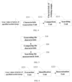
- an identification module 32 of the present embodiment is shown, which may include a characteristic generation unit 3211, a comparison unit 3212 and a searching unit 3213.
- the characteristic unit 3211 may generate the characteristics of the specified section image using the gray values of the pixels in the specified section image.
- the comparison unit 3212 may compare the characteristics of the specified section image with the characteristics of training samples of a preset training sample mode.
- the searching unit 3213 may search out the training sample of which the characteristics are most similar to the characteristics of the specified section image, and output the measurement items corresponding to the training sample searched out as the corresponding measurement items corresponding to the specified section image.
- the present embodiment further provides a machine learning identification method.
- the machine learning methods generally generate the characteristics of a plurality of samples by the information of training samples (a series of samples of which the measurement items are known) and compare the characteristics of the section sample to be measured with the characteristics of the training samples to determine which type of measurement items the section sample to be measured corresponds to.
- common machine learning methods may include principal component analysis (PCA) method, linear discriminant analysis (LDA) method, kernel principal component analysis (KPCA) method, locality preserving projections (LPP), support vector machine (SVM) method and artificial neural networks (ANNs), etc.
- PCA principal component analysis
- LDA linear discriminant analysis
- KPCA kernel principal component analysis
- LPP locality preserving projections
- SVM support vector machine
- ANNs artificial neural networks
- the dimensionality of the image data acquired by the image acquisition module 31 is very high.
- An image with sizes of W*H may be considered as a W*H-dimensional vector.
- a great relevance generally exists between the dimensions of this high-dimensional vector.
- the expression of high-dimensional data has great redundancy.
- One common method is projecting the high-dimensional data to a low-dimensional space to eliminate the redundancy between the dimensions of the data.
- PCA is this kind of method, of which the essence is finding out the projection which best represents the original high-dimensional data in the sense of least mean square. The present embodiment will be further described taking PCA as an example.
- a method for identification using the identification module above may include following steps.
- Step 510 generating the characteristics.
- the characteristics of the specified section image may be generated using the gray values of the pixels of the specified section image.
- the measurement items of the specified section image may be obtained by comparing the characteristics of the specified section image with the characteristics of the preset training samples. Therefore, firstly, the characteristics of the training samples and the characteristics of the specified section image may be acquired.
- the characteristics of the training samples and the characteristics of the specified section image may be the eigenvalues, the eigenvectors or combination of the eigenvalues and the eigenvectors.
- the characteristic of the training sample may be the projection coefficient of the eigenvectors of the training sample on the mean value of the training sample
- the characteristic of the specified section image may be the projection coefficient of the eigenvectors of the specified section image on the mean value of the training sample.
- L T is the transpose of matrix L.
- the eigenvalue matrix ⁇ may be a M*M diagonal matrix and the eigenvalues may be arranged in descending order, i.e., ⁇ 11 ⁇ ⁇ 22 ⁇ ⁇ MM , where ⁇ jj represents the element of the eigenvalue matrix ⁇ at j-th column and j-th row.
- n may be determined by a plurality of ways.
- n may be a preset constant.
- E T is the transpose matrix of the matrix E and F i is the characteristic of I i .
- This projection reduces the dimensionality of the sample from M*1 to n*1 and eliminates the correlation between the high-dimensional data.
- This n*1-dimensional data can best represent the original data in the sense of least mean square.
- the calculation of the step above to the sample library can be performed offline and the results of the calculation (for example, the characteristics F i of the matrix E and the training samples) may be stored in the apparatus.
- the gray values of all pixels of the section image may be acquired, which may be similarly expanded into a M-dimensional vector I test .
- w is the projection coefficient of the eigenvectors of the section image on the mean value of the training sample (i.e. the characteristic of the section image)
- I test is the eigenvectors of the section image
- m is the mean value of the training samples
- E is the orithogonalized eigenvector
- E T is the transpose matrix of the matrix E.
- the characteristics of the specified section image may be calculated by the formula (2).
- Step 520 comparing the characteristics.
- the characteristics of the specified section image may be compared with the characteristics of the plurality of training samples of the preset training sampSearchle mode.
- x i is the modulus of the comparison result of the characteristic of the specified section image with the characteristic of the i-th training sample F i , where 1 ⁇ i ⁇ N.
- the characteristic of the specified section image may be compared with the plurality of samples in the training sample library.
- Step 530 searching the measurement items.
- the training sample of which the characteristics are most similar to the characteristics of the specified section image may be searched out.
- the measurement items corresponding to the training sample which is searched out may be the measurement items of the specified section image.
- the function index represents the serial number (i) corresponding to the minimum of x i , which means that the i-th training sample is the one most similar to the sample being processed. Therefore, the measurement items of the sample being processed may be the same with the measurement items of the i-th training sample, which is known. Thereby, the measurement items corresponding to the specified section image are searched out.
- different measuring modes may correspond to different sample modes which have different sample libraries. Therefore, before comparing the characteristics in the step 520, the measuring mode selected by the user may be acquired to make a selection on the sample libraries to reduce the number of the samples participating the comparison, which not only can increase the identification efficiency, but also may further increase the identification accuracy.
- the machine learning method needs to acquire the characteristics of a plurality kinds of training samples and then perform the comparison, therefore it may be necessary to acquire training samples as many as possible, and these training samples should cover a variety of situations in position, size and shape, etc. as far as possible.
- image processing methods may be used.
- image processing methods may be used to extract the image features (such as the gray, shape or the like) of the section images to determine the measurement items.
- FIG. 6 an identification module 32 provided in the present embodiment is shown.
- the identification module 32 may include an extraction unit 3221, an identification unit 3222 and a determination unit 3223.
- the extraction unit 3221 may extract the high intensity portion of the specified section image based on the gray values of the pixels of the specified section image.
- the identification unit 3222 may identify the high intensity portion based on the measuring mode to determine the section type of the specified section image.
- the determination unit 3223 may determine the measurement items corresponding to the specified section image based on the section type determined and the measurement items corresponding thereto.
- the present embodiment also provides a method for identification of measurement items using the identification module above, which may extract the features (such as the gray, shape or the like) of the section image and then perform the analysis and determination using these features.
- the image processing methods used may vary with the measuring modes.
- the common measurement items may include head circumference (HC), biparietal diameter (BPD), abdominal circumference (AC) and femur length (FL).
- the head circumference and the abdominal circumference are elliptic objects
- the biparietal diameter and the femur length are linear object
- the head circumference and the biparietal diameter can be measured in a same section. Therefore, these four measurement items may correspond to three measurement sections: the head circumference section (HC and BPD may correspond to a same section), the abdominal circumference section and the femur section.
- the head circumference section contains the skull of the fetus, which is represented as a high intensity portion in an ultrasound section image. Furthermore, the skull in the near field and the skull in the far field together form an ellipse, in which the brain of the fetus is located. The gray values within the ellipse are significantly lower than the gray values of the skull. In the femur section, the femur is also represented as a high intensity portion, but the femur is substantially linear and only has a few curved portions. In the abdominal circumference section, the abdominal circumference is represented as an elliptic object with great gradient. However, the boundary of the abdominal circumference is not represented as high intensity portion, and the internal and the boundary of the abdominal circumference are close in gray value. Therefore, when the image processing methods are adopted to identify the measurement items, the measuring mode selected by the user may be acquired first, and then the image processing methods may be used to identify the measurement items.
- FIG. 7 a flow chart of the identification process of the present embodiment is shown.
- the methods of the present embodiment will be further described hereinafter taking the obstetric measuring mode as an example.
- the methods may include following steps.
- Step 600 acquiring the measuring mode.
- Step 610 extracting the high intensity portion.
- the high intensity portion in the specified section image may be extracted based on the gray values of the pixels of the specified section image.
- a preprocessing may be performed on the image and then the high intensity portion may be extracted based on the preprocessed image.
- the preprocessing may be mainly used to suppress the noise of the image, increase the continuity of the boundary and highlight the high intensity portion.
- preprocessing methods such as anisotropic smoothing, etc.
- the preprocessing may not be performed and the high intensity portion may be extracted based on the original gray data of the image.
- a cluster segmentation method may be used to extract the high intensity portion in the specified section image.
- the gray values of the pixels of the specified section image may be categorized into a plurality of categories using the cluster segmentation method.
- the pixels with the gray values of the one or more categories with maximum gray value may be kept unchanged while the pixels with the gray values of other categories may be assigned with zero, thereby obtaining a characteristic image.
- the N categories may be arranged in descending order and the first M categories (for example, M ⁇ 1 and M ⁇ N) may be determined as the category with maximum intensity (i.e. the high intensity portion).
- the pixels with the gray values of the following N-M categories may be assigned with zero while other pixels may be kept unchanged, thereby obtaining the characteristic image.
- Connected regions in the characteristic image may be identified, and one or more connected regions with maximum intensity may be determined, thereby obtaining the high intensity portion of the specified section image.
- the first X connected regions of the connected regions arranged in descending order may be determined as the connected regions with maximum intensity.
- X may be preset by the apparatus, and generally may be 1 ⁇ 10. In other embodiments, X may be other value based on actual needs.
- the characteristic image may also be obtained by convoluting a preset M ⁇ N operator with the specified section image.
- the values of the elements in the operator may be determined based on actual needs.
- the characteristic image may generally contain a lot of noise. Therefore, certain morphological operations (such as morphological corrosion, opening operation, removal of small areas or the like) may be performed on the characteristic image to remove the noise and increase the continuity of the boundaries in the image.
- certain morphological operations such as morphological corrosion, opening operation, removal of small areas or the like
- Step 620 identifying the type of the section.
- an identification method may be performed on the high intensity portion based on the measuring mode to determine the section type of the specified section image.
- both the head circumference and the abdominal circumference are substantially elliptic.
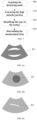
- the head circumference section (as shown in FIG. 8a ) and the abdominal circumference section (as shown in FIG. 8b ) mainly differ in that: the head circumference section contains the skulls 81 which is represented as high intensity echoes during ultrasound examination and other tissues of the head, which are represented as low intensity portion during the ultrasound examination and significantly different from the skulls 81 in intensity, are located within the head circumference; while the abdominal circumference section contains the abdomen 82 of the fetus, of which the boundary has lower intensity than the head circumference and within which the echoes is relatively uniform and has no much difference from those of the boundary.
- Both the head circumference and the femur section (as shown in FIG. 8c ) contain bones with high intensity, of which the main difference is that the head circumference contains two symmetrical, arc-shaped bones 81 while the femur section contains generally only one, relative straight bone 83.
- the intensity and shape of the connected regions identified may be analyzed and compared to determine which type of section the section image belong to.
- an intensity threshold for the connected regions may be set in order to determine whether bones are contained in the section image. For example, in the case that the mean intensity of the connected regions is greater than a first threshold, the specified section image contains bones; in the case that the mean intensity of the connected regions is lower than a second threshold, the specified section image does not contain bones. The first threshold is greater than the second threshold. In other embodiments, it is also possible that only one intensity threshold for the connected regions is set.
- a simple method for the analysis of the shape of the bones is using curvature to determine whether the bone bends and the degree of the bending.
- curvature thresholds may be set.
- the specified section image contains curved bone; in the case that the curvature of the connected regions is lower than a curvature threshold, the specified section image does not contain curved bone.
- the curvature may be defined as the angle between two lines formed by respectively connecting the point located at the middle of the connected region and the points located at the both ends of the connected region.
- the curvature may be defined in other ways as long as it can represent the degree of the bending of the connected regions.
- the specified section image contains bones and the section may be the head circumference section or the femur section.
- the curvature of the connected regions may be considered.
- the curvatures are greater than a certain threshold, it is determined that the bones contained in the section are curved and the specified section is the head circumference section.
- the curvatures are lower than a certain threshold, it is determined that the bones contained in the section are straight and the specified section is the femur section.
- the mean intensities of the X connected regions are all lower than a certain threshold, it is determined that the specified section does not contain bones with high intensity and is an abdominal section.
- Step 630 determining the measurement items.
- the measurement items corresponding to the specified section image may be determined based on the section type determined and the measurement items corresponding thereto.
- the programs may be stored in a computer-readable storage medium which may include ROM, RAM, disk or CD, etc.
Landscapes
- Health & Medical Sciences (AREA)
- Life Sciences & Earth Sciences (AREA)
- Engineering & Computer Science (AREA)
- Physics & Mathematics (AREA)
- Medical Informatics (AREA)
- General Health & Medical Sciences (AREA)
- Public Health (AREA)
- Pathology (AREA)
- Biomedical Technology (AREA)
- Animal Behavior & Ethology (AREA)
- Heart & Thoracic Surgery (AREA)
- Surgery (AREA)
- Veterinary Medicine (AREA)
- Biophysics (AREA)
- Molecular Biology (AREA)
- Radiology & Medical Imaging (AREA)
- Nuclear Medicine, Radiotherapy & Molecular Imaging (AREA)
- Computer Vision & Pattern Recognition (AREA)
- Artificial Intelligence (AREA)
- Physiology (AREA)
- Theoretical Computer Science (AREA)
- General Physics & Mathematics (AREA)
- Rheumatology (AREA)
- Fuzzy Systems (AREA)
- Signal Processing (AREA)
- Gynecology & Obstetrics (AREA)
- Pregnancy & Childbirth (AREA)
- Psychiatry (AREA)
- Geometry (AREA)
- Orthopedic Medicine & Surgery (AREA)
- Mathematical Physics (AREA)
- Dentistry (AREA)
- Oral & Maxillofacial Surgery (AREA)
- Quality & Reliability (AREA)
- Evolutionary Computation (AREA)
- Data Mining & Analysis (AREA)
- Databases & Information Systems (AREA)
- Epidemiology (AREA)
- Primary Health Care (AREA)
- Ultra Sonic Daignosis Equipment (AREA)
Claims (9)
- Ein computergestütztes Verfahren zur automatischen Erkennung eines Messobjekts, das Folgendes umfasst:einen Vorgang zur Bilderfassung (410): Erfassen von Grauwerten von Pixeln eines bestimmten Bildausschnitts, wobei die Grauwerte der Pixel Ultraschallechos entsprechen, die durch Reflexion von Ultraschallwellen durch ein zu untersuchendes Gewebe erzeugt werden;einen Vorgang zur Identifizierung (420): Erkennen von mindestens einem Messpunkt, entsprechend dem bestimmten Bildausschnitt auf der Grundlage der Grauwerte der Pixel; undeinen Messvorgang (430): Messen eines Messparameters des bestimmten Bildausschnitts auf der Grundlage des erkannten Messobjekts; dadurch gekennzeichnet, dass der Vorgang zurIdentifizierung Folgendes umfasst: Erstellen einer Charakteristik (510) des bestimmten Bildausschnitts basierend auf den Grauwerten der Pixel des bestimmten Bildausschnitts, Vergleich der Charakteristik des bestimmten Bildausschnitts mit den Eigenschaften des Schulungsmusters, Suchen (530) eines Schulungsmusters, dessen Charakteristik der Eigenschaften des bestimmten Bildausschnitts am ähnlichsten ist, und Ausgeben von Messwerten, die dem gesuchten Schulungsmuster und als Messwerte dem bestimmten Bildausschnitt entsprechen, wobei die Charakteristika der Schulungsmuster und die Charakteristika des bestimmten Bildausschnitts Eigenwerte, Eigenvektoren oder Kombinationen von Eigenwerten und Eigenvektoren sind, die für die Grauwerte der Pixel der jeweiligen Bilder kennzeichnend sind.
- Verfahren nach Anspruch 1, wobei im Vorgang zur Identifizierung (420) das Messobjekt auf der Grundlage einer vergleichenden Analyse der Grauwerte der Pixel mit einer physikalischen Eigenschaft der dem Messobjekt entsprechenden Ausschnitte erkannt wird.
- Verfahren nach einem der Ansprüche 1 oder 2, wobei vor dem Vorgang zur Identifizierung ein Messmodus (440) erfasst wird, der während der Gewebeuntersuchung verwendet wird.
- Verfahren nach Anspruch 1, wobei die Charakteristik des Schulungsmusters ein Projektionskoeffizient eines Eigenvektors des Schulungsmusters auf einen Mittelwert des Schulungsmusters ist und die Charakteristik des bestimmten Bildausschnitts einen Projektionskoeffizienten eines Eigenvektors des bestimmten Bildausschnitts auf den Mittelwert des Schulungsmusters darstellt.
- Vorrichtung zur automatischen Identifizierung eines Messobjekts, die Folgendes umfasst:ein Bilderfassungsmodul (31), das so ausgelegt ist, dass es Grauwerte von Pixeln eines bestimmten Bildausschnitts erfasst, wobei die Grauwerte der Pixel Ultraschallechos entsprechen, die durch Reflexion von Ultraschallwellen an einem untersuchten Gewebe erzeugt werden;ein Identifizierungsmodul (32), das so ausgelegt ist, dass es auf der Grundlage der Grauwerte der Pixel mindestens ein Messobjekt erkennt, das dem bestimmten Bildausschnitt entspricht; undein Messmodul (33), das so ausgelegt ist, dass es einen Messparameter des bestimmten Bildausschnitts auf der Grundlage des erkannten Messobjekts misst; dadurch gekennzeichnet, dass das Identifikationsmodul eine Charakteristik-Erzeugungseinheit (3211) umfasst, die so ausgelegt ist, dass sie eine Charakteristik des bestimmten Bildausschnitts auf der Grundlage der Grauwerte der Pixel des bestimmten Bildausschnitts erzeugt; eine Vergleichseinheit (3212), die so ausgelegt ist, dass sie die Eigenschaft des bestimmten Bildausschnitts mit Charakteristika von Schulungsmustern vergleichen, eine Sucheinheit (3213), die so ausgelegt ist, dass sie ein Schulungsmuster sucht, dessen Eigenschaft der Charakteristik des bestimmten Bildausschnitts am ähnlichsten ist, und Messwerte ausgibt, die dem herausgesuchten Schulungsmuster als Messwerte entsprechen, die dem bestimmten Bildausschnitt entsprechen, wobei die Charakteristika der Schulungsmuster und die Charakteristika desdes bestimmten Bildausschnitts Eigenwerte, Eigenvektoren oder Kombinationen von Eigenwerten und Eigenvektoren sind, die für die Grauwerte der Pixel der jeweiligen Bilder repräsentativ sind.
- Vorrichtung nach Anspruch 5, wobei das Identifikationsmodul (32) so ausgelegt ist, dass es das Messobjekt auf der Grundlage einer vergleichenden Analyse der Grauwerte der Pixel mit einer physikalischen Eigenschaft der dem Messobjekt entsprechenden Abschnitte erkennt.
- Vorrichtung nach einem der Ansprüche 5 oder 6, die ferner ein Messmodus-Erfassungsmodul (34) umfasst, das einen während der Gewebeuntersuchung verwendeten Messmodus erfasst.
- Vorrichtung nach Anspruch 5, wobei die Charakteristik des Schulungsmusters einem Projektionskoeffizient eines Eigenvektors des Schulungsmusters auf einen Mittelwert des Schulungsmusters entspricht, und die Charakteristik des bestimmten Bildausschnitts einem Projektionskoeffizient eines Eigenvektors des bestimmten Bildausschnitts auf den Mittelwert des Schulungsmusters entspricht.
- Ein Ultraschall-Bildgebungsgerät mit:einer Sonde (1), die so ausgelegt ist, dass sie Ultraschallwellen auf ein Gewebe überträgt und Ultraschallechos empfängt;einem Signalverarbeitungsgerät (2), das so ausgelegt ist, dass es die Ultraschallechos verarbeitet, um Ultraschallbilddaten zu erzeugen; undeinem Bildverarbeitungsgerät (3), das zur Verarbeitung der Ultraschallbilddaten ausgelegt ist und Bildausschnitte erzeugt;wobei das Bildverarbeitungsgerät (3) eine Vorrichtung zur automatischen Erkennung eines Messobjekts nach einem der Ansprüche 5 bis 8 umfasst.
Applications Claiming Priority (1)
| Application Number | Priority Date | Filing Date | Title |
|---|---|---|---|
| PCT/CN2014/073777 WO2015139267A1 (zh) | 2014-03-20 | 2014-03-20 | 自动识别测量项的方法、装置及一种超声成像设备 |
Publications (4)
| Publication Number | Publication Date |
|---|---|
| EP3127486A1 EP3127486A1 (de) | 2017-02-08 |
| EP3127486A4 EP3127486A4 (de) | 2018-01-24 |
| EP3127486B1 true EP3127486B1 (de) | 2024-07-31 |
| EP3127486C0 EP3127486C0 (de) | 2024-07-31 |
Family
ID=54143685
Family Applications (1)
| Application Number | Title | Priority Date | Filing Date |
|---|---|---|---|
| EP14885962.2A Active EP3127486B1 (de) | 2014-03-20 | 2014-03-20 | Verfahren und vorrichtung zur automatischen identifikation eines messelements und ultraschallbildgebungsvorrichtung |
Country Status (4)
| Country | Link |
|---|---|
| US (3) | US10898109B2 (de) |
| EP (1) | EP3127486B1 (de) |
| CN (2) | CN110811691B (de) |
| WO (1) | WO2015139267A1 (de) |
Families Citing this family (32)
| Publication number | Priority date | Publication date | Assignee | Title |
|---|---|---|---|---|
| US10154826B2 (en) | 2013-07-17 | 2018-12-18 | Tissue Differentiation Intelligence, Llc | Device and method for identifying anatomical structures |
| US10716536B2 (en) | 2013-07-17 | 2020-07-21 | Tissue Differentiation Intelligence, Llc | Identifying anatomical structures |
| EP3127486B1 (de) | 2014-03-20 | 2024-07-31 | Shenzhen Mindray Bio-Medical Electronics Co., Ltd. | Verfahren und vorrichtung zur automatischen identifikation eines messelements und ultraschallbildgebungsvorrichtung |
| US11986341B1 (en) | 2016-05-26 | 2024-05-21 | Tissue Differentiation Intelligence, Llc | Methods for accessing spinal column using B-mode imaging to determine a trajectory without penetrating the the patient's anatomy |
| WO2017206023A1 (zh) * | 2016-05-30 | 2017-12-07 | 深圳迈瑞生物医疗电子股份有限公司 | 一种心脏容积识别分析系统和方法 |
| US11701086B1 (en) | 2016-06-21 | 2023-07-18 | Tissue Differentiation Intelligence, Llc | Methods and systems for improved nerve detection |
| WO2018129737A1 (zh) | 2017-01-16 | 2018-07-19 | 深圳迈瑞生物医疗电子股份有限公司 | 超声图像中参数测量的方法和超声成像系统 |
| CN110520933B (zh) * | 2017-03-01 | 2023-10-27 | 皇家飞利浦有限公司 | 超声心动图上下文测量工具 |
| US10918357B2 (en) * | 2017-06-30 | 2021-02-16 | General Electric Company | Methods and systems for automatically determining an anatomical measurement of ultrasound images |
| JP6836652B2 (ja) * | 2017-08-25 | 2021-03-03 | 富士フイルム株式会社 | 音響波診断装置および音響波診断装置の制御方法 |
| CN108078592A (zh) * | 2017-12-29 | 2018-05-29 | 深圳开立生物医疗科技股份有限公司 | 超声图像处理方法及装置、超声诊断装置、可读存储介质 |
| CN109044398B (zh) * | 2018-06-07 | 2021-10-19 | 深圳华声医疗技术股份有限公司 | 超声系统成像方法、装置及计算机可读存储介质 |
| CN112367921B (zh) * | 2018-07-02 | 2024-09-24 | 富士胶片株式会社 | 声波诊断装置及声波诊断装置的控制方法 |
| CN109276274A (zh) * | 2018-10-26 | 2019-01-29 | 深圳开立生物医疗科技股份有限公司 | 一种超声图像标准切面识别及测量方法和超声诊断设备 |
| CN121730889A (zh) * | 2018-10-26 | 2026-03-27 | 深圳开立生物医疗科技股份有限公司 | 一种超声图像标准切面提取及测量方法和超声诊断设备 |
| CN109589139A (zh) * | 2018-12-06 | 2019-04-09 | 深圳开立生物医疗科技股份有限公司 | 一种超声测量生物量自动确认方法和超声诊断系统 |
| CN109589140B (zh) * | 2018-12-26 | 2022-04-01 | 深圳开立生物医疗科技股份有限公司 | 一种超声测量多项目处理方法和超声诊断系统 |
| CN109589141A (zh) * | 2018-12-28 | 2019-04-09 | 深圳开立生物医疗科技股份有限公司 | 一种超声诊断辅助方法、系统和超声诊断设备 |
| CN111374698B (zh) * | 2018-12-29 | 2024-11-19 | 深圳迈瑞生物医疗电子股份有限公司 | 超声成像系统及相关的工作流系统和方法 |
| CN109925002A (zh) * | 2019-01-15 | 2019-06-25 | 胡秋明 | 人工智能超声心动图数据采集系统及其数据采集方法 |
| KR102765007B1 (ko) | 2019-05-15 | 2025-02-11 | 삼성메디슨 주식회사 | 초음파 영상 장치 및 그 표시 방법 |
| CN110680399B (zh) * | 2019-10-25 | 2020-12-29 | 深圳度影医疗科技有限公司 | 一种产前超声图像的自动测量方法、存储介质及超声设备 |
| WO2021120065A1 (zh) * | 2019-12-18 | 2021-06-24 | 深圳迈瑞生物医疗电子股份有限公司 | 解剖结构的自动测量方法和超声成像系统 |
| CN114072059B (zh) * | 2019-12-27 | 2024-09-06 | 深圳迈瑞生物医疗电子股份有限公司 | 一种超声成像设备以及快速设置超声自动工作流的方法 |
| CN111862072A (zh) * | 2020-07-29 | 2020-10-30 | 南通大学 | 一种基于ct图像测量腹围的方法 |
| JP7410624B2 (ja) | 2020-09-14 | 2024-01-10 | キヤノン株式会社 | 超音波診断装置、計測条件設定方法及びプログラム |
| CN112370078B (zh) * | 2020-11-10 | 2024-01-26 | 安徽理工大学 | 一种基于超声成像和贝叶斯优化的图像检测方法 |
| CN115530872A (zh) * | 2021-06-29 | 2022-12-30 | 深圳开立生物医疗科技股份有限公司 | 一种超声诊断系统、设备、介质 |
| CN113274056A (zh) * | 2021-06-30 | 2021-08-20 | 深圳开立生物医疗科技股份有限公司 | 一种超声扫查方法及相关装置 |
| CN114587339B (zh) * | 2022-01-24 | 2025-07-22 | 中国标准化研究院 | 一种尺寸编码辨识度工效学测量器具及辨识方法 |
| US11944501B2 (en) * | 2022-02-16 | 2024-04-02 | GE Precision Healthcare LLC | Systems and methods for automatic measurements of medical images |
| CN116356525B (zh) * | 2022-12-23 | 2026-03-13 | 珠海格力电器股份有限公司 | 洗烘设备控制方法、装置、洗烘设备和存储介质 |
Family Cites Families (23)
| Publication number | Priority date | Publication date | Assignee | Title |
|---|---|---|---|---|
| US5588435A (en) * | 1995-11-22 | 1996-12-31 | Siemens Medical Systems, Inc. | System and method for automatic measurement of body structures |
| US5795296A (en) * | 1996-03-29 | 1998-08-18 | University Of Washington | Pipeline process for automatically measuring object boundary from ultrasound image samples |
| US5605155A (en) * | 1996-03-29 | 1997-02-25 | University Of Washington | Ultrasound system for automatically measuring fetal head size |
| US6258033B1 (en) * | 1999-11-30 | 2001-07-10 | Agilent Technologies, Inc. | Ultrasound method employing echoes from a region of interest to enable quantization of backscatter signals |
| US6561980B1 (en) * | 2000-05-23 | 2003-05-13 | Alpha Intervention Technology, Inc | Automatic segmentation of prostate, rectum and urethra in ultrasound imaging |
| JP4614548B2 (ja) * | 2001-01-31 | 2011-01-19 | パナソニック株式会社 | 超音波診断装置 |
| US6733454B1 (en) * | 2003-02-26 | 2004-05-11 | Siemens Medical Solutions Usa, Inc. | Automatic optimization methods and systems for doppler ultrasound imaging |
| US7563229B2 (en) * | 2003-06-11 | 2009-07-21 | Ge Medical Systems Global Technology Company Llc | Method and apparatus for automatically measuring delay of tissue motion and deformation |
| ITPI20040066A1 (it) * | 2004-09-21 | 2004-12-21 | Cnr Consiglio Naz Delle Ricerche | Metodo e dispositivo per la valutazione automatica di indici di funzionalita' cardiovascolare mediante elaborazione di immagini ecografiche |
| KR100747093B1 (ko) * | 2005-01-12 | 2007-08-07 | 주식회사 메디슨 | 초음파 진단 영상을 이용한 대상체의 경계를 자동으로검출하는 방법 및 초음파 진단 시스템 |
| JP4701011B2 (ja) * | 2005-05-31 | 2011-06-15 | ジーイー・メディカル・システムズ・グローバル・テクノロジー・カンパニー・エルエルシー | 超音波診断装置 |
| EP2072013A4 (de) * | 2006-10-10 | 2014-12-03 | Hitachi Medical Corp | Medizinisches bilddiagnosegerät, medizinisches bildmessverfahren und medizinisches bildmessprogramm |
| US8556814B2 (en) * | 2007-10-04 | 2013-10-15 | Siemens Medical Solutions Usa, Inc. | Automated fetal measurement from three-dimensional ultrasound data |
| IT1391829B1 (it) * | 2008-11-21 | 2012-01-27 | C N R Consiglio Naz Delle Ricerche | Apparato basato sugli ultrasuoni per misurare parametri indicatori di avanzamento di un parto |
| CN101785681B (zh) * | 2010-01-13 | 2012-06-20 | 北京航空航天大学 | 婴儿头骨发育状况定量测量与分析系统 |
| US20110196236A1 (en) * | 2010-02-08 | 2011-08-11 | Gokul Swamy | System and method of automated gestational age assessment of fetus |
| US10426430B2 (en) * | 2010-08-26 | 2019-10-01 | Koninklijke Philips N.V. | Automated three dimensional aortic root measurement and modeling |
| CN102151149B (zh) * | 2010-12-24 | 2013-01-23 | 深圳市理邦精密仪器股份有限公司 | 一种胎儿超声图像自动测量方法及系统 |
| CN102274051B (zh) * | 2011-05-27 | 2012-12-26 | 深圳市理邦精密仪器股份有限公司 | 一种超声图像膀胱容积自动测量方法及系统 |
| EP4057215A1 (de) * | 2013-10-22 | 2022-09-14 | Eyenuk, Inc. | Systeme und verfahren zur automatischen analyse von netzhautbildern |
| EP3127486B1 (de) * | 2014-03-20 | 2024-07-31 | Shenzhen Mindray Bio-Medical Electronics Co., Ltd. | Verfahren und vorrichtung zur automatischen identifikation eines messelements und ultraschallbildgebungsvorrichtung |
| US10806391B2 (en) * | 2016-09-26 | 2020-10-20 | General Electric Company | Method and system for measuring a volume of an organ of interest |
| US10970837B2 (en) * | 2019-03-18 | 2021-04-06 | Siemens Healthcare Gmbh | Automated uncertainty estimation of lesion segmentation |
-
2014
- 2014-03-20 EP EP14885962.2A patent/EP3127486B1/de active Active
- 2014-03-20 WO PCT/CN2014/073777 patent/WO2015139267A1/zh not_active Ceased
- 2014-03-20 CN CN201911159310.7A patent/CN110811691B/zh active Active
- 2014-03-20 CN CN201480047617.7A patent/CN105555198B/zh active Active
-
2016
- 2016-09-20 US US15/271,095 patent/US10898109B2/en active Active
-
2021
- 2021-01-08 US US17/144,786 patent/US11717183B2/en active Active
-
2023
- 2023-06-19 US US18/211,516 patent/US12336808B2/en active Active
Also Published As
| Publication number | Publication date |
|---|---|
| US20170007161A1 (en) | 2017-01-12 |
| US11717183B2 (en) | 2023-08-08 |
| US10898109B2 (en) | 2021-01-26 |
| EP3127486A4 (de) | 2018-01-24 |
| CN110811691A (zh) | 2020-02-21 |
| US12336808B2 (en) | 2025-06-24 |
| US20230329581A1 (en) | 2023-10-19 |
| EP3127486C0 (de) | 2024-07-31 |
| CN105555198A (zh) | 2016-05-04 |
| CN110811691B (zh) | 2022-08-05 |
| CN105555198B (zh) | 2019-12-24 |
| US20210128020A1 (en) | 2021-05-06 |
| WO2015139267A1 (zh) | 2015-09-24 |
| EP3127486A1 (de) | 2017-02-08 |
Similar Documents
| Publication | Publication Date | Title |
|---|---|---|
| US12336808B2 (en) | Method and device for automatic identification of measurement item and ultrasound imaging apparatus | |
| US11633169B2 (en) | Apparatus for AI-based automatic ultrasound diagnosis of liver steatosis and remote medical diagnosis method using the same | |
| US11229419B2 (en) | Method for processing 3D image data and 3D ultrasonic imaging method and system | |
| JP6467041B2 (ja) | 超音波診断装置、及び画像処理方法 | |
| CN110945560B (zh) | 胎儿超声图像处理 | |
| Berton et al. | Segmentation of the spinous process and its acoustic shadow in vertebral ultrasound images | |
| US11464490B2 (en) | Real-time feedback and semantic-rich guidance on quality ultrasound image acquisition | |
| KR101580254B1 (ko) | 주파수 영역에서의 의료 영상 진단 장치 및 방법 | |
| WO2013025692A1 (en) | A method and system of characterization of carotid plaque | |
| KR100490564B1 (ko) | 초음파 영상 신호로부터 장기를 인식하는 장치 및 방법 | |
| CN114155243B (zh) | 基于特征信息的ivus和oct图像融合方法及系统 | |
| CN111820948B (zh) | 胎儿生长参数测量方法、系统及超声设备 | |
| US20150055840A1 (en) | Ultrasound Image Object Boundary Localization by Intensity Histogram Classification Using Relationships Among Boundaries | |
| CN106491161A (zh) | 一种智能组织识别的方法及装置 | |
| JP3928978B1 (ja) | 医用画像処理装置、医用画像処理方法及びプログラム | |
| CN112998755A (zh) | 解剖结构的自动测量方法和超声成像系统 | |
| Parida et al. | Quantitative metrics for benchmarking medical image harmonization | |
| EP3554339B1 (de) | System zur medizinischen bildgebung | |
| US20220249060A1 (en) | Method for processing 3d image data and 3d ultrasonic imaging method and system | |
| CN118557219A (zh) | 超声成像系统及超声图像显示方法 | |
| CN110163907A (zh) | 胎儿颈部透明层厚度测量方法、设备及存储介质 | |
| CN117934356A (zh) | 一种超声成像系统和卵巢间质自动定量分析方法 | |
| Vansteenkiste | Quantitative analysis of ultrasound images of the preterm brain | |
| de Siqueira et al. | Localization of cardiac cavities using hierarchically search in 2D grayscale ultrasound images |
Legal Events
| Date | Code | Title | Description |
|---|---|---|---|
| STAA | Information on the status of an ep patent application or granted ep patent |
Free format text: STATUS: THE INTERNATIONAL PUBLICATION HAS BEEN MADE |
|
| PUAI | Public reference made under article 153(3) epc to a published international application that has entered the european phase |
Free format text: ORIGINAL CODE: 0009012 |
|
| STAA | Information on the status of an ep patent application or granted ep patent |
Free format text: STATUS: REQUEST FOR EXAMINATION WAS MADE |
|
| 17P | Request for examination filed |
Effective date: 20160919 |
|
| AK | Designated contracting states |
Kind code of ref document: A1 Designated state(s): AL AT BE BG CH CY CZ DE DK EE ES FI FR GB GR HR HU IE IS IT LI LT LU LV MC MK MT NL NO PL PT RO RS SE SI SK SM TR |
|
| AX | Request for extension of the european patent |
Extension state: BA ME |
|
| DAX | Request for extension of the european patent (deleted) | ||
| A4 | Supplementary search report drawn up and despatched |
Effective date: 20180104 |
|
| RIC1 | Information provided on ipc code assigned before grant |
Ipc: A61B 8/00 20060101AFI20171221BHEP |
|
| STAA | Information on the status of an ep patent application or granted ep patent |
Free format text: STATUS: EXAMINATION IS IN PROGRESS |
|
| 17Q | First examination report despatched |
Effective date: 20210330 |
|
| 111L | Licence recorded |
Designated state(s): AT BE BG CY CZ DE DK EE ES FI FR GR HR HU IE IT LT LU LV MT NL PL PT RO SE SI SK SM Name of requester: SHENZHEN MINDRAY ANIMAL MEDICAL TECHNOLOGY CO., LTD., CN Effective date: 20221025 |
|
| 111L | Licence recorded |
Designated state(s): AT BE BG CY CZ DE DK EE ES FI FR GB GR HR HU IE IT LT LU LV MT NL PL PT RO SE SI SK SM Name of requester: SHENZHEN MINDRAY ANIMAL MEDICAL TECHNOLOGY CO., LTD., CN Effective date: 20221025 |
|
| GRAP | Despatch of communication of intention to grant a patent |
Free format text: ORIGINAL CODE: EPIDOSNIGR1 |
|
| STAA | Information on the status of an ep patent application or granted ep patent |
Free format text: STATUS: GRANT OF PATENT IS INTENDED |
|
| INTG | Intention to grant announced |
Effective date: 20240313 |
|
| GRAS | Grant fee paid |
Free format text: ORIGINAL CODE: EPIDOSNIGR3 |
|
| GRAA | (expected) grant |
Free format text: ORIGINAL CODE: 0009210 |
|
| STAA | Information on the status of an ep patent application or granted ep patent |
Free format text: STATUS: THE PATENT HAS BEEN GRANTED |
|
| 111L | Licence recorded |
Designated state(s): AT BE BG CY CZ DE DK EE ES FI FR GB GR HR HU IE IT LT LU LV MT NL PL PT RO SE SI SK SM Name of requester: SHENZHEN MINDRAY ANIMAL MEDICALTECHNOLOGY CO., LTD., CN Effective date: 20221025 |
|
| AK | Designated contracting states |
Kind code of ref document: B1 Designated state(s): AL AT BE BG CH CY CZ DE DK EE ES FI FR GB GR HR HU IE IS IT LI LT LU LV MC MK MT NL NO PL PT RO RS SE SI SK SM TR |
|
| REG | Reference to a national code |
Ref country code: CH Ref legal event code: EP Ref country code: GB Ref legal event code: FG4D |
|
| REG | Reference to a national code |
Ref country code: DE Ref legal event code: R096 Ref document number: 602014090616 Country of ref document: DE |
|
| REG | Reference to a national code |
Ref country code: IE Ref legal event code: FG4D |
|
| U01 | Request for unitary effect filed |
Effective date: 20240731 |
|
| U07 | Unitary effect registered |
Designated state(s): AT BE BG DE DK EE FI FR IT LT LU LV MT NL PT SE SI Effective date: 20240812 |
|
| PG25 | Lapsed in a contracting state [announced via postgrant information from national office to epo] |
Ref country code: NO Free format text: LAPSE BECAUSE OF FAILURE TO SUBMIT A TRANSLATION OF THE DESCRIPTION OR TO PAY THE FEE WITHIN THE PRESCRIBED TIME-LIMIT Effective date: 20241031 |
|
| PG25 | Lapsed in a contracting state [announced via postgrant information from national office to epo] |
Ref country code: PL Free format text: LAPSE BECAUSE OF FAILURE TO SUBMIT A TRANSLATION OF THE DESCRIPTION OR TO PAY THE FEE WITHIN THE PRESCRIBED TIME-LIMIT Effective date: 20240731 Ref country code: GR Free format text: LAPSE BECAUSE OF FAILURE TO SUBMIT A TRANSLATION OF THE DESCRIPTION OR TO PAY THE FEE WITHIN THE PRESCRIBED TIME-LIMIT Effective date: 20241101 |
|
| PG25 | Lapsed in a contracting state [announced via postgrant information from national office to epo] |
Ref country code: IS Free format text: LAPSE BECAUSE OF FAILURE TO SUBMIT A TRANSLATION OF THE DESCRIPTION OR TO PAY THE FEE WITHIN THE PRESCRIBED TIME-LIMIT Effective date: 20241130 |
|
| PG25 | Lapsed in a contracting state [announced via postgrant information from national office to epo] |
Ref country code: HR Free format text: LAPSE BECAUSE OF FAILURE TO SUBMIT A TRANSLATION OF THE DESCRIPTION OR TO PAY THE FEE WITHIN THE PRESCRIBED TIME-LIMIT Effective date: 20240731 |
|
| PG25 | Lapsed in a contracting state [announced via postgrant information from national office to epo] |
Ref country code: RS Free format text: LAPSE BECAUSE OF FAILURE TO SUBMIT A TRANSLATION OF THE DESCRIPTION OR TO PAY THE FEE WITHIN THE PRESCRIBED TIME-LIMIT Effective date: 20241031 Ref country code: ES Free format text: LAPSE BECAUSE OF FAILURE TO SUBMIT A TRANSLATION OF THE DESCRIPTION OR TO PAY THE FEE WITHIN THE PRESCRIBED TIME-LIMIT Effective date: 20240731 |
|
| PG25 | Lapsed in a contracting state [announced via postgrant information from national office to epo] |
Ref country code: RS Free format text: LAPSE BECAUSE OF FAILURE TO SUBMIT A TRANSLATION OF THE DESCRIPTION OR TO PAY THE FEE WITHIN THE PRESCRIBED TIME-LIMIT Effective date: 20241031 Ref country code: PL Free format text: LAPSE BECAUSE OF FAILURE TO SUBMIT A TRANSLATION OF THE DESCRIPTION OR TO PAY THE FEE WITHIN THE PRESCRIBED TIME-LIMIT Effective date: 20240731 Ref country code: NO Free format text: LAPSE BECAUSE OF FAILURE TO SUBMIT A TRANSLATION OF THE DESCRIPTION OR TO PAY THE FEE WITHIN THE PRESCRIBED TIME-LIMIT Effective date: 20241031 Ref country code: IS Free format text: LAPSE BECAUSE OF FAILURE TO SUBMIT A TRANSLATION OF THE DESCRIPTION OR TO PAY THE FEE WITHIN THE PRESCRIBED TIME-LIMIT Effective date: 20241130 Ref country code: HR Free format text: LAPSE BECAUSE OF FAILURE TO SUBMIT A TRANSLATION OF THE DESCRIPTION OR TO PAY THE FEE WITHIN THE PRESCRIBED TIME-LIMIT Effective date: 20240731 Ref country code: GR Free format text: LAPSE BECAUSE OF FAILURE TO SUBMIT A TRANSLATION OF THE DESCRIPTION OR TO PAY THE FEE WITHIN THE PRESCRIBED TIME-LIMIT Effective date: 20241101 Ref country code: ES Free format text: LAPSE BECAUSE OF FAILURE TO SUBMIT A TRANSLATION OF THE DESCRIPTION OR TO PAY THE FEE WITHIN THE PRESCRIBED TIME-LIMIT Effective date: 20240731 |
|
| PG25 | Lapsed in a contracting state [announced via postgrant information from national office to epo] |
Ref country code: SM Free format text: LAPSE BECAUSE OF FAILURE TO SUBMIT A TRANSLATION OF THE DESCRIPTION OR TO PAY THE FEE WITHIN THE PRESCRIBED TIME-LIMIT Effective date: 20240731 |
|
| PG25 | Lapsed in a contracting state [announced via postgrant information from national office to epo] |
Ref country code: CZ Free format text: LAPSE BECAUSE OF FAILURE TO SUBMIT A TRANSLATION OF THE DESCRIPTION OR TO PAY THE FEE WITHIN THE PRESCRIBED TIME-LIMIT Effective date: 20240731 |
|
| PG25 | Lapsed in a contracting state [announced via postgrant information from national office to epo] |
Ref country code: SK Free format text: LAPSE BECAUSE OF FAILURE TO SUBMIT A TRANSLATION OF THE DESCRIPTION OR TO PAY THE FEE WITHIN THE PRESCRIBED TIME-LIMIT Effective date: 20240731 |
|
| U20 | Renewal fee for the european patent with unitary effect paid |
Year of fee payment: 12 Effective date: 20250325 |
|
| PLBE | No opposition filed within time limit |
Free format text: ORIGINAL CODE: 0009261 |
|
| STAA | Information on the status of an ep patent application or granted ep patent |
Free format text: STATUS: NO OPPOSITION FILED WITHIN TIME LIMIT |
|
| 26N | No opposition filed |
Effective date: 20250501 |
|
| PG25 | Lapsed in a contracting state [announced via postgrant information from national office to epo] |
Ref country code: MC Free format text: LAPSE BECAUSE OF FAILURE TO SUBMIT A TRANSLATION OF THE DESCRIPTION OR TO PAY THE FEE WITHIN THE PRESCRIBED TIME-LIMIT Effective date: 20240731 |
|
| REG | Reference to a national code |
Ref country code: CH Ref legal event code: H13 Free format text: ST27 STATUS EVENT CODE: U-0-0-H10-H13 (AS PROVIDED BY THE NATIONAL OFFICE) Effective date: 20251024 |
|
| PG25 | Lapsed in a contracting state [announced via postgrant information from national office to epo] |
Ref country code: CH Free format text: LAPSE BECAUSE OF NON-PAYMENT OF DUE FEES Effective date: 20250331 |
|
| PG25 | Lapsed in a contracting state [announced via postgrant information from national office to epo] |
Ref country code: IE Free format text: LAPSE BECAUSE OF NON-PAYMENT OF DUE FEES Effective date: 20250320 |
|
| PGFP | Annual fee paid to national office [announced via postgrant information from national office to epo] |
Ref country code: GB Payment date: 20260324 Year of fee payment: 13 |
|
| PG25 | Lapsed in a contracting state [announced via postgrant information from national office to epo] |
Ref country code: RO Free format text: LAPSE BECAUSE OF FAILURE TO SUBMIT A TRANSLATION OF THE DESCRIPTION OR TO PAY THE FEE WITHIN THE PRESCRIBED TIME-LIMIT Effective date: 20240731 |
|
| U20 | Renewal fee for the european patent with unitary effect paid |
Year of fee payment: 13 Effective date: 20260326 |