EP3127670A2 - Procédé d'imprégnation de plaques de matière première - Google Patents
Procédé d'imprégnation de plaques de matière première Download PDFInfo
- Publication number
- EP3127670A2 EP3127670A2 EP16187300.5A EP16187300A EP3127670A2 EP 3127670 A2 EP3127670 A2 EP 3127670A2 EP 16187300 A EP16187300 A EP 16187300A EP 3127670 A2 EP3127670 A2 EP 3127670A2
- Authority
- EP
- European Patent Office
- Prior art keywords
- material plate
- strand
- transport device
- individual
- plates
- Prior art date
- Legal status (The legal status is an assumption and is not a legal conclusion. Google has not performed a legal analysis and makes no representation as to the accuracy of the status listed.)
- Granted
Links
Images

Classifications
-
- B—PERFORMING OPERATIONS; TRANSPORTING
- B27—WORKING OR PRESERVING WOOD OR SIMILAR MATERIAL; NAILING OR STAPLING MACHINES IN GENERAL
- B27N—MANUFACTURE BY DRY PROCESSES OF ARTICLES, WITH OR WITHOUT ORGANIC BINDING AGENTS, MADE FROM PARTICLES OR FIBRES CONSISTING OF WOOD OR OTHER LIGNOCELLULOSIC OR LIKE ORGANIC MATERIAL
- B27N7/00—After-treatment, e.g. reducing swelling or shrinkage, surfacing; Protecting the edges of boards against access of humidity
-
- B—PERFORMING OPERATIONS; TRANSPORTING
- B27—WORKING OR PRESERVING WOOD OR SIMILAR MATERIAL; NAILING OR STAPLING MACHINES IN GENERAL
- B27N—MANUFACTURE BY DRY PROCESSES OF ARTICLES, WITH OR WITHOUT ORGANIC BINDING AGENTS, MADE FROM PARTICLES OR FIBRES CONSISTING OF WOOD OR OTHER LIGNOCELLULOSIC OR LIKE ORGANIC MATERIAL
- B27N1/00—Pretreatment of moulding material
- B27N1/02—Mixing the material with binding agent
- B27N1/029—Feeding; Proportioning; Controlling
-
- B—PERFORMING OPERATIONS; TRANSPORTING
- B27—WORKING OR PRESERVING WOOD OR SIMILAR MATERIAL; NAILING OR STAPLING MACHINES IN GENERAL
- B27N—MANUFACTURE BY DRY PROCESSES OF ARTICLES, WITH OR WITHOUT ORGANIC BINDING AGENTS, MADE FROM PARTICLES OR FIBRES CONSISTING OF WOOD OR OTHER LIGNOCELLULOSIC OR LIKE ORGANIC MATERIAL
- B27N3/00—Manufacture of substantially flat articles, e.g. boards, from particles or fibres
- B27N3/08—Moulding or pressing
- B27N3/18—Auxiliary operations, e.g. preheating, humidifying, cutting-off
-
- B—PERFORMING OPERATIONS; TRANSPORTING
- B27—WORKING OR PRESERVING WOOD OR SIMILAR MATERIAL; NAILING OR STAPLING MACHINES IN GENERAL
- B27N—MANUFACTURE BY DRY PROCESSES OF ARTICLES, WITH OR WITHOUT ORGANIC BINDING AGENTS, MADE FROM PARTICLES OR FIBRES CONSISTING OF WOOD OR OTHER LIGNOCELLULOSIC OR LIKE ORGANIC MATERIAL
- B27N9/00—Arrangements for fireproofing
Definitions
- the invention relates to a method for impregnating material plates, in particular wood fiber boards, material plates produced by this method and a system for carrying out the method.
- MDF medium density fibreboard
- HDF high density fibreboard
- a property may be, for example, the conductivity that is or is desired for a fiberboard in either powder coating the panel itself or when the panel is to be used as a laminate flooring panel support and the flooring must have antistatic properties.
- the conductivity can be achieved by adding salts in the manufacturing process, for example in the refining process.
- Another desired property may be a fire retardant design.
- vacuum and “vacuum” are used synonymously. By this is meant that a suitable negative pressure is generated and applied whose value is less than that of the prevailing atmospheric pressure and / or the overpressure also used according to some aspects of the invention.
- prepolymers based on low molecular weight isocyanates can be used for this process.
- the impregnating material is usually pressed into the material by pressure in a press and this impregnation process is assisted by a negative pressure applied from the underside of the plate. Excess prepolymer is collected in catchment channels on the underside and returned to the process.
- the impregnating agent is usually applied only in those areas where later cutting edges or profiles are.
- Object of the present invention is therefore to provide a method which overcomes the disadvantages of the prior art.
- the invention is therefore based on the technical problem of finding a technology that the above-described Solves problems or achieves significant simplifications in terms of the procedure.
- the invention thus relates to a method for impregnating material plates, in particular wood fiber boards, in which one places individual material plates or a continuous material plate strand on a transport device such that the individual material plates arranged one behind the other as an endless strand of material plates rest on the transport device or the continuous material plate strand rests on the transport device, the strand of individual material plates or the continuous material plate strand is continuously guided through an impregnation station for introducing an impregnation medium into the material plates or the material plate strand, wherein the impregnation medium is applied by means of a plurality of application devices, which are arranged in at least one row over the full width of the individual material plate or the continuous material plate strand and individually controllable, time-controlled during the continued transporting the individual material plates of the strand or the continuous material plate strand.
- the term "endless strand of material plates” is understood to mean a continuous sequence of material plates which are located on the transport device are arranged one behind the other and thereby form a strand (or continuous stream) of individual plates during the impregnation process, which during the impregnation process (ie during the movement of the transport device) by the supply of new, yet to be impregnated material plates at one end (the “beginning”). ) of the transport device and by the corresponding removal of the already impregnated material plates at the other end (the "end") of the transport device, continuously renewed and thus during the impregnation process is "endless".
- an alternative method for impregnating material plates in particular wood fiber plates, in which one gives up individual material plates on a transport device such that the material plates abut each other with their edges and rest as an endless strand of material plates on the transport device, the endless strand of material plates continuously an impregnating station for introducing an impregnating medium into the material plates leads "whereby the impregnating medium is applied by means of a plurality of application devices, which are arranged in a row over the full width of the material plate and individually controllable, time-controlled during the continued transporting the endless strand of material plates.
- the individual application devices of the multiplicity of application devices are timed so that each individual application device emits impregnation medium only at a preselected time.
- a method is preferred in which the timing of the application devices is synchronized with the speed of transport of the individual material plates of the strand or of the continuous material plate strand, wherein the transport of the individual material plates of the strand or of the continuous material plate strand takes place by means of the transport device.
- Timing of the application devices and / or the synchronization of the transport device are controlled and / or regulated by means of a processor.
- Particularly preferred is also a method in which the impregnating medium is applied by means of a plurality of applicators in the form of applicator heads, the applicator heads pressing the impregnating medium into the depth of the material plates using overpressure.
- Very particularly preferred is a method in which the spatial distribution of the impregnation medium in the depth of the material plate is controlled by controlling the overpressure in the application device and / or the negative pressure, acting from the other side on the material plate, pretending accordingly.
- Also according to the invention is a process in which the impregnating medium is used in liquid, dissolved or suspended form or as an emulsion.
- the impregnating medium alters the water absorption and / or the swelling and / or the strength values and / or the flammability of the material plate.
- the material panels are made of wood-based materials, of mineral-bonded wood materials or of mineral materials or of a combination of these materials or contain them.
- an endless strand is first formed from a stack of plates.
- the material plates can be arranged on the transport device so that adjacent plates with their (opposite) edges abut each other (thus touching on these edges) or, alternatively, that the plates are separated by a distance from each other on the transport device (themselves so do not touch). It is also conceivable that the plates are arranged on the transport device, that some of the plates at their edges abut (so touching) and other plates do not touch at their edges.
- This strand thus formed passes through driven rollers accelerated under a impregnating station.
- the plates are additionally fixed in this area by mangle rollers.
- an impregnating agent is under pressure in the Pressed plates.
- This process is supported by counter-bars on the back of the plates, where a negative pressure is applied.
- These are also movable and are each positioned under the pressure bar.
- the application nozzles can be controlled individually and optionally also be operated differently from the order quantities.
- a material slab strand can also be used in the method according to the invention.
- a material plate strand may for example be previously formed from corresponding wood fibers and in the form of a cake, which is then further processed after impregnation to a corresponding material plate.
- An advantage of the method according to the invention is that the incorporation of the impregnating medium into the material plate can take place in any desired pattern. This makes it possible, if necessary, to provide each plate with a different pattern. If, for example, planks are to be formed from the plate, this can be done by the appropriate control of the multiplicity of application devices for the impregnating medium. If the following plate is then to be provided for square panels, then the impregnation can be changed by Actuation of the plurality of application devices for the impregnating carried out. As a result, an economical and effective introduction of the impregnation is accomplished.
- the inventive method is applicable to a variety of plate types.
- the suitability for the use of certain plate types is essentially influenced by the density and the porosity of the material.
- the impregnation method according to the invention is controlled by the application of pressure and vacuum. Therefore, in addition to wood-based panels such as wood fiber boards, other mineral-bonded wood-based materials (cements) (cement-bonded chipboard) and mineral board materials (fiber cement) are also suitable and preferred for the process according to the invention.
- cement-bonded chipboard cement-bonded chipboard
- fiber cement mineral board materials
- the object of the invention is also achieved by an impregnated material plate, which has the characteristics of the sibling, directed to an impregnated material plate, claim.
- the subject of the present invention is therefore also an impregnated material plate produced by the process according to the invention.
- the invention relates to impregnated material plates, in particular wood fiber boards, obtainable by a method in which places individual material plates or a continuous material plate strand on a transport device such that the individual material plates arranged one behind the other as an endless strand of material plates on the Resting transport device or the continuous material plate strand rests on the transport device, the strand of individual material plates or the continuous material plate strand is continuously guided through an impregnation station for introducing an impregnation medium into the material plates or the material plate strand, wherein the impregnation medium is applied by means of a plurality of application devices, which are arranged in at least one row over the full width of the individual material plate or the continuous material plate strand and individually controllable, time-controlled during the continued transporting the individual material plates of the strand or the continuous material plate strand.
- an impregnated material plate wherein the impregnation medium is introduced into the depth of the material plate by means of a negative pressure, which acts on the material plate from the underside of the transport device through openings in the transport device, is preferred.
- an impregnated material plate is preferred, wherein the individual application devices of the plurality of application devices are timed in such a way that each individual application device emits impregnation medium only at a preselected time.
- an impregnated material plate wherein synchronized the timing of the applicators with the speed of transport of the arranged, wherein the transport of the individual material plates of the strand or the continuous Material plate strand is done by means of the transport device.
- Preference is also impregnated material plate, wherein controlling the timing of the applicators and / or the synchronization of the transport device by means of a processor and / or controls.
- impregnated material plate wherein the impregnating medium is applied by means of a plurality of application devices in the form of nozzles.
- impregnated material plate wherein the impregnation medium is applied by means of a plurality of application devices in the form of applicator heads, wherein the application heads press the impregnation medium into the depth of the material plates using overpressure.
- Also preferred according to the invention is an impregnated material plate, wherein the spatial distribution of the impregnation medium in the depth of the material plate is controlled by predetermining the overpressure in the application device and / or the negative pressure acting on the material plate from the other side.
- impregnated material plate wherein the impregnation medium is used in liquid, dissolved or suspended form or as an emulsion.
- an impregnated material plate wherein the impregnation changes the water absorption and / or the swelling and / or the strength values and / or the flammability of the material plate.
- an impregnated material plate wherein the material plate is formed from wood materials, from mineral bonded wood materials or mineral materials or from a combination of these materials or contains these.
- the object of the invention is also achieved by a system which has the characteristics of the sibling, directed at a facility, claim.
- Advantageous developments of the system according to the invention are characterized in the dependent claims.
- Another object of the present invention is a system for carrying out the method according to the invention.
- the invention thus relates to a system for producing an impregnated material plate, comprising a transport device and an impregnation station arranged above the transport device, wherein the impregnation station is provided with a multiplicity of application devices which are arranged in a row over the full width of the transport device and each individual application device has at least one control element which can be controlled individually.
- the impregnation further includes a vacuum station, which is arranged below the transport device and having a plurality of suction devices, so arranged for each above the transport device applicator disposed below the transport device suction device is arranged and each suction device at least one control has, which is individually controlled.
- Particularly preferred is a system in which the application devices are designed as nozzles.
- Particularly preferred is also a system in which the application devices are designed as applicator heads.
- the applicator heads rest with their side boundaries on the surface of the material to be impregnated plate and optionally provided with seals. It is particularly preferred that the application heads are arranged in two parallel rows over the full width of the transport device. It is highly preferred that the distance between the two rows is mutually variable.
- a processor is furthermore provided for controlling the control elements of the application devices and / or for controlling the suction devices and / or for controlling the transport device.
- the claimed system operates according to the following method:
- the method is further characterized in that the impregnation medium is introduced into the depth of the material plate 1 by means of a negative pressure, which acts on the material plate 1 from the underside of the transport device 11 through openings in the transport device 11.
- the method is further characterized in that the individual application devices 13 of the plurality of application devices 13 are timed such that each individual application device 13 delivers impregnation medium only at a preselected time and / or the timing of the application devices 13 at the speed of transport synchronized individual material plates 1 of the strand or the continuous material plate strand, wherein the transport of the endless strand of material plates 1 by means of the transport device 11 takes place.
- the method is further characterized in that one controls and / or regulates the timing of the application devices 13 and / or the synchronization of the transport device 11 by means of a processor.
- the method is further characterized in that the application heads 14 press the impregnation medium into the depth of the material plates 1 using overpressure.
- the method is further characterized in that one controls the spatial distribution of the impregnating medium in the depth of the material plate 1 by setting the overpressure in the applicator 13 and / or the negative pressure acting on the material plate 1 from the other side accordingly ,
- the process is further characterized in that the impregnating medium is used in liquid, dissolved or suspended form or as an emulsion.
- the method is further characterized in that the impregnation medium changes the water absorption and / or the swelling and / or the strength values and / or the flammability of the material plate 1 and / or that the material plates 1 are made of wood materials, of minerally bound wood materials or of mineral materials or are formed from or contain a combination of these materials.
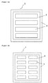
- FIG. 1 with the sub-figures 1a, 1b and 1c shows different produced by the process according to the invention impregnated material plates 1.
- Die FIGS. 1a and 1b each show a material plate 1 with impregnated areas 2 and unimpregnated areas 3.
- the impregnated regions 2 can be made very different in geometry.
- An impregnation pattern according to FIG. 1 is suitable for later cutting the material plate, which is then a fiberboard, in planks, which are then provided with tongue and groove to allow a glueless installation.
- the impregnated fiberboard is then suitable to be cut into small panel elements.
- the respective impregnation patterns can be produced using the method according to the invention.
- the impregnation pattern can be applied in one operation, wherein both the impregnations along the direction of the plates and transverse to the direction can be formed in a single pass through the impregnation.
- the targeted control for example, only the outer application devices of the plurality of application devices, an impregnation in the direction of the transport device is achieved and only at the edge of the material plates. If, for example, only one of the application devices is subsequently actuated in succession in such a way that always the respectively adjacent applicator on the right is addressed, an impregnation arises which extends diagonally across the material plate.
- any pattern can be generated by the corresponding, targeted control.
- Such patterns may be rectangles, squares, diamonds, trapezoids or even circles. These patterns are available in a simple manner by the targeted and individual control of the individual applicators.
- the Figure 1c again shows a material plate 1 with impregnated areas 2 and unimpregnated areas 3.
- the impregnated areas 2 are each arranged around a saw cut 4 to be attached later.
- the saw cut 4 causes this material to be removed later. It is therefore not necessary to first treat this later saw cut 4 with impregnating material in order to then remove this area again.
- this impregnation pattern can be applied to the material plates by means of an applicator device arranged in two parallel rows.
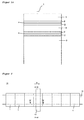
- FIG. 2 shows an impregnation plant 10 for carrying out the method according to the invention.
- the individual material plates 1 are placed on a transport device 11.
- the individual plates 1 abut each other, so that an endless strand of material plates 1 is formed.
- This endless strand is then moved in the transport direction R and passes through the impregnation station 12.
- a plurality of application devices 13 (not shown) are arranged inside the impregnation station 12.
- a vacuum station 19 below the transport device 11 may further be arranged a vacuum station 19 (not shown), which consists of a plurality of suction devices 15 (not shown).
- the impregnation plant may comprise, in addition to the constituents mentioned, other stations in which the material plates are processed. In particular, a drying station may be provided.
- FIG. 3 now shows a section through an impregnation station 12 along the section line AA of FIG. 2 ,
- the material plate 1 rests on the transport device 11 and is guided by this through the impregnation 12.
- a plurality of application devices 13 is arranged above the material plate 1.
- These applicators 13 advantageously each have a seal 17, which closes the applicator 13 to the top of the material plate 1 out.
- This seal 17 is provided with a contact pressure which is sufficient to achieve the sealing effect, but is chosen so that a transport of the plate 1 is still possible.
- Each applicator is further provided with a control 16. This control regulates the inflow and possibly also the pressure of the applied impregnating medium.
- the application devices 13 are connected to a corresponding supply and / or delivery system for the impregnation media.
- the vacuum station 19 includes a plurality of suction devices 15.
- the transport device is configured accordingly, so that it is designed for the passage of pressure differences.
- the suction devices 15 with the plate 1 are advantageously in turn seals 17 are provided.
- the individual suction devices 15 furthermore have control elements 16 which regulate the vacuum to be applied.
- control devices 16 of the application devices 13 and the suction devices 15 are each independently and independently designed to be controllable and controllable. This makes it possible to individually design the application of the impregnating medium and the introduction into the material plate 1 and to form any desired patterns on the surface and in the depth of the material plate 1.
- a processor (not shown) is advantageously provided. This processor is part of a computer-controlled measuring and control device.
- the applicator 13 may be formed in different ways. Nozzles can be used, whereby the seal 17 can not be required.
- the application device can also be designed as an application head 14. These guns can have different geometric shapes. They can be rectangular or square or circular. This form is determined by the chemical, physical and rheological properties of the impregnation medium. The skilled person is able to choose the shape accordingly.
- FIG. 4 a particularly designed according to the invention applicator head is shown.
- the FIG. 4 represents the interior of the impregnation station 12 along the section line BB of FIG. 2
- the application head is divided and the partial application heads have a defined distance to each other.
- the division of the application heads 14 can be effected by providing two rows of applicator heads 14 arranged parallel to each other.
- the use of the split head reduces the losses of impregnant.
- the impregnation takes place on the back of the later product, because thus also a saving of the impregnating agent can be achieved.
- Through variable control of the pressure and the amount applied impregnations can be controlled in their geometry. At much pressure and application quantity, linear impregnation images ( FIG. 4 , left part), with low pressure and reduced order quantity rather funnel-shaped order images ( FIG. 4 , right part). Thus, a considerable saving in the relatively expensive impregnating materials can be achieved. In the case of a full impregnation, part of the impregnating material would be removed again during sawing or cutting.
- multiple impregnations and impregnations with multi-component materials are also possible.
- multiple or multi-component impregnations can be carried out in one operation, for example isocyanates + polyols, paraffin + color, etc.
Landscapes
- Life Sciences & Earth Sciences (AREA)
- Engineering & Computer Science (AREA)
- Manufacturing & Machinery (AREA)
- Wood Science & Technology (AREA)
- Forests & Forestry (AREA)
- Dry Formation Of Fiberboard And The Like (AREA)
- Chemical And Physical Treatments For Wood And The Like (AREA)
Applications Claiming Priority (2)
| Application Number | Priority Date | Filing Date | Title |
|---|---|---|---|
| DE102012100800.0A DE102012100800B4 (de) | 2012-01-31 | 2012-01-31 | Verfahren zum Imprägnieren von Werkstoffplatten, imprägnierte Werkstoffplatte und Anlage zur Herstellung einer imprägnierten Werkstoffplatte |
| EP13153560.1A EP2623282B1 (fr) | 2012-01-31 | 2013-01-31 | Procédé d'imprégnation de plaques de matière première |
Related Parent Applications (1)
| Application Number | Title | Priority Date | Filing Date |
|---|---|---|---|
| EP13153560.1A Division EP2623282B1 (fr) | 2012-01-31 | 2013-01-31 | Procédé d'imprégnation de plaques de matière première |
Publications (4)
| Publication Number | Publication Date |
|---|---|
| EP3127670A2 true EP3127670A2 (fr) | 2017-02-08 |
| EP3127670A3 EP3127670A3 (fr) | 2017-08-23 |
| EP3127670B1 EP3127670B1 (fr) | 2024-04-10 |
| EP3127670C0 EP3127670C0 (fr) | 2024-04-10 |
Family
ID=47681724
Family Applications (2)
| Application Number | Title | Priority Date | Filing Date |
|---|---|---|---|
| EP13153560.1A Active EP2623282B1 (fr) | 2012-01-31 | 2013-01-31 | Procédé d'imprégnation de plaques de matière première |
| EP16187300.5A Active EP3127670B1 (fr) | 2012-01-31 | 2013-01-31 | Procédé d'imprégnation de plaques de matière première |
Family Applications Before (1)
| Application Number | Title | Priority Date | Filing Date |
|---|---|---|---|
| EP13153560.1A Active EP2623282B1 (fr) | 2012-01-31 | 2013-01-31 | Procédé d'imprégnation de plaques de matière première |
Country Status (5)
| Country | Link |
|---|---|
| EP (2) | EP2623282B1 (fr) |
| DE (2) | DE102012100800B4 (fr) |
| ES (1) | ES2599812T3 (fr) |
| PL (1) | PL2623282T3 (fr) |
| PT (1) | PT2623282T (fr) |
Cited By (4)
| Publication number | Priority date | Publication date | Assignee | Title |
|---|---|---|---|---|
| US20180243936A1 (en) * | 2017-02-24 | 2018-08-30 | Cefla Deutschland Gmbh | Process for Preparing a Flame Retardant and/or Strengthened Fiberboard |
| EP3727771A4 (fr) * | 2017-12-20 | 2021-11-17 | Burnblock Holding APS | Imprégnation ignifuge de plaques en bois |
| EP4166294A1 (fr) * | 2021-10-18 | 2023-04-19 | SWISS KRONO Tec AG | Procédé de fabrication d'une plaque en matériau dérivé du bois et dispositif de fabrication de plaques en matériau dérivé du bois |
| EP4368361A1 (fr) * | 2022-11-09 | 2024-05-15 | SWISS KRONO Tec AG | Procédé de fabrication d'une plaque de particules de copeaux grossiers et dispositif de fabrication de plaque de copeaux de grand diamètre |
Families Citing this family (4)
| Publication number | Priority date | Publication date | Assignee | Title |
|---|---|---|---|---|
| DE102015206941A1 (de) * | 2015-04-17 | 2016-11-10 | Cefla Deutschland Gmbh | Verfahren zum Herstellen einer Faserplatte mit verbesserten chemischen und mechanischen Eigenschaften |
| EP3916170A1 (fr) | 2015-05-12 | 2021-12-01 | Aladdin Manufacturing Corporation | Panneau de plancher |
| PL3470191T3 (pl) | 2017-10-16 | 2020-07-13 | SWISS KRONO Tec AG | Sposób i urządzenie do produkowania płyty drewnopochodnej |
| EP4699767A1 (fr) * | 2024-08-19 | 2026-02-25 | Yangi AB | Unité de formation de produit et procédé de fabrication à sec de produits cellulosiques rigides |
Citations (3)
| Publication number | Priority date | Publication date | Assignee | Title |
|---|---|---|---|---|
| DE19963203A1 (de) | 1999-12-27 | 2001-09-20 | Kunnemeyer Hornitex | Verfahren zum Herstellen von plattenförmigen Holzwerkstoffen und Platte aus Holzwerkstoff |
| DE102008049132A1 (de) | 2008-09-26 | 2010-04-08 | Flooring Technologies Ltd. | Verfahren zum Herstellen einer Holzfaserplatte und Holzfaserplattenherstellvorrichtung |
| EP2241426A1 (fr) | 2009-04-17 | 2010-10-20 | Flooring Technologies Ltd. | Procede de fabrication d'un panneau de fibres |
Family Cites Families (4)
| Publication number | Priority date | Publication date | Assignee | Title |
|---|---|---|---|---|
| DE19857045C2 (de) * | 1998-12-10 | 2001-02-01 | Industrieservis Ges Fuer Innov | Beschichtung von Gegenständen |
| GB0505879D0 (en) * | 2005-03-22 | 2005-04-27 | Ten Cate Advanced Textiles Bv | Composition for continuous inkjet finishing of a textile article |
| DE102007044315B4 (de) * | 2007-09-17 | 2013-11-28 | Flooring Technologies Ltd. | Holzwerkstoffplattenvergütungsvorrichtung und Verfahren zum Herstellen einer Holzwerkstoffplatte |
| DE102008034749B3 (de) * | 2008-07-24 | 2010-01-28 | Flooring Technologies Ltd. | Holzwerkstoffplatte |
-
2012
- 2012-01-31 DE DE102012100800.0A patent/DE102012100800B4/de not_active Expired - Fee Related
-
2013
- 2013-01-29 DE DE202013100406U patent/DE202013100406U1/de not_active Expired - Lifetime
- 2013-01-31 EP EP13153560.1A patent/EP2623282B1/fr active Active
- 2013-01-31 ES ES13153560.1T patent/ES2599812T3/es active Active
- 2013-01-31 PT PT131535601T patent/PT2623282T/pt unknown
- 2013-01-31 PL PL13153560T patent/PL2623282T3/pl unknown
- 2013-01-31 EP EP16187300.5A patent/EP3127670B1/fr active Active
Patent Citations (3)
| Publication number | Priority date | Publication date | Assignee | Title |
|---|---|---|---|---|
| DE19963203A1 (de) | 1999-12-27 | 2001-09-20 | Kunnemeyer Hornitex | Verfahren zum Herstellen von plattenförmigen Holzwerkstoffen und Platte aus Holzwerkstoff |
| DE102008049132A1 (de) | 2008-09-26 | 2010-04-08 | Flooring Technologies Ltd. | Verfahren zum Herstellen einer Holzfaserplatte und Holzfaserplattenherstellvorrichtung |
| EP2241426A1 (fr) | 2009-04-17 | 2010-10-20 | Flooring Technologies Ltd. | Procede de fabrication d'un panneau de fibres |
Cited By (9)
| Publication number | Priority date | Publication date | Assignee | Title |
|---|---|---|---|---|
| US20180243936A1 (en) * | 2017-02-24 | 2018-08-30 | Cefla Deutschland Gmbh | Process for Preparing a Flame Retardant and/or Strengthened Fiberboard |
| EP3388213A3 (fr) * | 2017-02-24 | 2019-01-09 | Cefla Deutschland GmbH | Procédé de fabrication d'un panneau de fibres difficilement inflammable et/ou consolidé |
| EP3727771A4 (fr) * | 2017-12-20 | 2021-11-17 | Burnblock Holding APS | Imprégnation ignifuge de plaques en bois |
| EP4166294A1 (fr) * | 2021-10-18 | 2023-04-19 | SWISS KRONO Tec AG | Procédé de fabrication d'une plaque en matériau dérivé du bois et dispositif de fabrication de plaques en matériau dérivé du bois |
| WO2023066802A1 (fr) | 2021-10-18 | 2023-04-27 | SWISS KRONO Tec AG | Procédé de fabrication d'un panneau en matériau dérivé du bois et dispositif de fabrication de panneaux en matériau dérivé du bois |
| US20240391131A1 (en) * | 2021-10-18 | 2024-11-28 | SWISS KRONO Tec AG | Method for producing a wooden composite board, and device for producing a wooden composite board |
| EP4596227A3 (fr) * | 2021-10-18 | 2025-10-15 | SWISS KRONO Tec AG | Procédé de fabrication d'une plaque en matériau dérivé du bois et dispositif de fabrication de plaques en matériau dérivé du bois |
| EP4368361A1 (fr) * | 2022-11-09 | 2024-05-15 | SWISS KRONO Tec AG | Procédé de fabrication d'une plaque de particules de copeaux grossiers et dispositif de fabrication de plaque de copeaux de grand diamètre |
| WO2024100015A1 (fr) | 2022-11-09 | 2024-05-16 | SWISS KRONO Tec AG | Procédé de production d'un panneau de copeaux orientés et dispositif de production de panneaux de copeaux orientés |
Also Published As
| Publication number | Publication date |
|---|---|
| EP3127670B1 (fr) | 2024-04-10 |
| EP2623282B1 (fr) | 2016-09-14 |
| PL2623282T3 (pl) | 2017-02-28 |
| DE102012100800A1 (de) | 2013-10-10 |
| ES2599812T3 (es) | 2017-02-03 |
| EP2623282A1 (fr) | 2013-08-07 |
| DE102012100800B4 (de) | 2021-08-05 |
| EP3127670C0 (fr) | 2024-04-10 |
| EP3127670A3 (fr) | 2017-08-23 |
| PT2623282T (pt) | 2016-12-09 |
| DE202013100406U1 (de) | 2013-03-04 |
Similar Documents
| Publication | Publication Date | Title |
|---|---|---|
| EP2623282B1 (fr) | Procédé d'imprégnation de plaques de matière première | |
| DE4333614C2 (de) | Verfahren und Anlage zur kontinuierlichen Herstellung von Spanplatten | |
| DE69511242T2 (de) | Verfahren zum herstellen von lignocelluloseplatten | |
| EP3275611B1 (fr) | Procédé de fabrication d'un panneau de fibres | |
| EP3028829B1 (fr) | Installation pour la fabrication d'un panneau en bois agglomeré | |
| EP3216574A1 (fr) | Procede de fabrication d'un osb | |
| EP3693144B1 (fr) | Procédé et dispositif de traitement partiel de la surface ou de la coupe transversale complète d'une plaque en matériau dérivé du bois ou d'un non-tissé en matériau dérivé du bois précomprimé ou d'un gâteau en fibre de bois | |
| EP0173873B1 (fr) | Procédé de fabrication en continu de plaques en fibro-béton | |
| EP1894711B1 (fr) | Procédé et dispositif destinés à la fabrication d'un panneau de construction léger | |
| EP4378650B1 (fr) | Procédé de fabrication d'osb et dispositif de fabrication d'osb | |
| EP3294511A1 (fr) | Procédé et dispositif pour disperser un mat au cours de la fabrication de panneaux de matériaux et panneau de matériau | |
| DE10054002C2 (de) | Etagenpresse, insbesondere Einetagen- oder Mehretagenpresse | |
| EP4005757B1 (fr) | Procédé et installation de fabrication de panneaux de matière | |
| EP3909733B1 (fr) | Procédé et système de fabrication d'une plaque déformée tridimensionnelle | |
| DE10315922A1 (de) | Verfahren und Anlage zur Herstellung von Plattenwerkstoffen | |
| WO2023232598A1 (fr) | Procédé de fabrication de panneaux osb et dispositif de production de panneaux osb | |
| WO2023066802A1 (fr) | Procédé de fabrication d'un panneau en matériau dérivé du bois et dispositif de fabrication de panneaux en matériau dérivé du bois | |
| WO2016180881A1 (fr) | Procédé et dispositif pour disperser un mat au cours de la fabrication de panneaux de matériaux et panneau de matériau | |
| DE202015102415U1 (de) | Vorrichtung zum Streuen eines Vlieses im Zuge der Herstellung von Werkstoffplatten und eine Werkstoffplatte | |
| DE202015102414U1 (de) | Vorrichtung zum Streuen eines Vlieses im Zuge der Herstellung von Werkstoffplatten und eine Werkstoffplatte | |
| DE19820810A1 (de) | Verfahren und Anlage zur Herstellung von Holzspanplatten | |
| DE102017119400A1 (de) | Verfahren zum Beschichten eines platten- oder bahnförmigen Materials und Vorrichtung zum Durchführen des Verfahrens | |
| EP2388117A1 (fr) | Procédé et installation de fabrication d'une plaque en fibres de bois | |
| DE102016108583A1 (de) | Vorrichtung zum Besprühen einer Materialbahn, insbesondere zum Befeuchten von Streugutmatten | |
| EP2786849A1 (fr) | Procédé de fabrication d'un panneau de fibres multicouche, et panneau de fibres multicouche |
Legal Events
| Date | Code | Title | Description |
|---|---|---|---|
| PUAI | Public reference made under article 153(3) epc to a published international application that has entered the european phase |
Free format text: ORIGINAL CODE: 0009012 |
|
| STAA | Information on the status of an ep patent application or granted ep patent |
Free format text: STATUS: THE APPLICATION HAS BEEN PUBLISHED |
|
| AC | Divisional application: reference to earlier application |
Ref document number: 2623282 Country of ref document: EP Kind code of ref document: P |
|
| AK | Designated contracting states |
Kind code of ref document: A2 Designated state(s): AL AT BE BG CH CY CZ DE DK EE ES FI FR GB GR HR HU IE IS IT LI LT LU LV MC MK MT NL NO PL PT RO RS SE SI SK SM TR |
|
| PUAL | Search report despatched |
Free format text: ORIGINAL CODE: 0009013 |
|
| RIC1 | Information provided on ipc code assigned before grant |
Ipc: B27N 1/02 20060101ALI20170712BHEP Ipc: B27N 7/00 20060101AFI20170712BHEP Ipc: B27N 3/18 20060101ALI20170712BHEP |
|
| AK | Designated contracting states |
Kind code of ref document: A3 Designated state(s): AL AT BE BG CH CY CZ DE DK EE ES FI FR GB GR HR HU IE IS IT LI LT LU LV MC MK MT NL NO PL PT RO RS SE SI SK SM TR |
|
| RAP1 | Party data changed (applicant data changed or rights of an application transferred) |
Owner name: FLOORING TECHNOLOGIES LTD. |
|
| RAP1 | Party data changed (applicant data changed or rights of an application transferred) |
Owner name: FLOORING TECHNOLOGIES LTD. |
|
| STAA | Information on the status of an ep patent application or granted ep patent |
Free format text: STATUS: REQUEST FOR EXAMINATION WAS MADE |
|
| 17P | Request for examination filed |
Effective date: 20171130 |
|
| RBV | Designated contracting states (corrected) |
Designated state(s): AL AT BE BG CH CY CZ DE DK EE ES FI FR GB GR HR HU IE IS IT LI LT LU LV MC MK MT NL NO PL PT RO RS SE SI SK SM TR |
|
| STAA | Information on the status of an ep patent application or granted ep patent |
Free format text: STATUS: EXAMINATION IS IN PROGRESS |
|
| 17Q | First examination report despatched |
Effective date: 20210401 |
|
| REG | Reference to a national code |
Ref country code: DE Ref legal event code: R079 Free format text: PREVIOUS MAIN CLASS: B27N0007000000 Ipc: B27N0003180000 Ref country code: DE Ref legal event code: R079 Ref document number: 502013016513 Country of ref document: DE Free format text: PREVIOUS MAIN CLASS: B27N0007000000 Ipc: B27N0003180000 |
|
| GRAP | Despatch of communication of intention to grant a patent |
Free format text: ORIGINAL CODE: EPIDOSNIGR1 |
|
| STAA | Information on the status of an ep patent application or granted ep patent |
Free format text: STATUS: GRANT OF PATENT IS INTENDED |
|
| RIC1 | Information provided on ipc code assigned before grant |
Ipc: B27N 9/00 20060101ALI20231223BHEP Ipc: B27N 1/02 20060101ALI20231223BHEP Ipc: B27N 7/00 20060101ALI20231223BHEP Ipc: B27N 3/18 20060101AFI20231223BHEP |
|
| INTG | Intention to grant announced |
Effective date: 20240123 |
|
| GRAS | Grant fee paid |
Free format text: ORIGINAL CODE: EPIDOSNIGR3 |
|
| GRAA | (expected) grant |
Free format text: ORIGINAL CODE: 0009210 |
|
| STAA | Information on the status of an ep patent application or granted ep patent |
Free format text: STATUS: THE PATENT HAS BEEN GRANTED |
|
| AC | Divisional application: reference to earlier application |
Ref document number: 2623282 Country of ref document: EP Kind code of ref document: P |
|
| AK | Designated contracting states |
Kind code of ref document: B1 Designated state(s): AL AT BE BG CH CY CZ DE DK EE ES FI FR GB GR HR HU IE IS IT LI LT LU LV MC MK MT NL NO PL PT RO RS SE SI SK SM TR |
|
| REG | Reference to a national code |
Ref country code: GB Ref legal event code: FG4D Free format text: NOT ENGLISH |
|
| REG | Reference to a national code |
Ref country code: CH Ref legal event code: EP |
|
| REG | Reference to a national code |
Ref country code: DE Ref legal event code: R096 Ref document number: 502013016513 Country of ref document: DE |
|
| REG | Reference to a national code |
Ref country code: IE Ref legal event code: FG4D Free format text: LANGUAGE OF EP DOCUMENT: GERMAN |
|
| U01 | Request for unitary effect filed |
Effective date: 20240419 |
|
| U07 | Unitary effect registered |
Designated state(s): AT BE BG DE DK EE FI FR IT LT LU LV MT NL PT SE SI Effective date: 20240426 |
|
| PG25 | Lapsed in a contracting state [announced via postgrant information from national office to epo] |
Ref country code: IS Free format text: LAPSE BECAUSE OF FAILURE TO SUBMIT A TRANSLATION OF THE DESCRIPTION OR TO PAY THE FEE WITHIN THE PRESCRIBED TIME-LIMIT Effective date: 20240810 |
|
| PG25 | Lapsed in a contracting state [announced via postgrant information from national office to epo] |
Ref country code: HR Free format text: LAPSE BECAUSE OF FAILURE TO SUBMIT A TRANSLATION OF THE DESCRIPTION OR TO PAY THE FEE WITHIN THE PRESCRIBED TIME-LIMIT Effective date: 20240410 |
|
| PG25 | Lapsed in a contracting state [announced via postgrant information from national office to epo] |
Ref country code: GR Free format text: LAPSE BECAUSE OF FAILURE TO SUBMIT A TRANSLATION OF THE DESCRIPTION OR TO PAY THE FEE WITHIN THE PRESCRIBED TIME-LIMIT Effective date: 20240711 |
|
| PG25 | Lapsed in a contracting state [announced via postgrant information from national office to epo] |
Ref country code: ES Free format text: LAPSE BECAUSE OF FAILURE TO SUBMIT A TRANSLATION OF THE DESCRIPTION OR TO PAY THE FEE WITHIN THE PRESCRIBED TIME-LIMIT Effective date: 20240410 |
|
| PG25 | Lapsed in a contracting state [announced via postgrant information from national office to epo] |
Ref country code: PL Free format text: LAPSE BECAUSE OF FAILURE TO SUBMIT A TRANSLATION OF THE DESCRIPTION OR TO PAY THE FEE WITHIN THE PRESCRIBED TIME-LIMIT Effective date: 20240410 |
|
| PG25 | Lapsed in a contracting state [announced via postgrant information from national office to epo] |
Ref country code: PL Free format text: LAPSE BECAUSE OF FAILURE TO SUBMIT A TRANSLATION OF THE DESCRIPTION OR TO PAY THE FEE WITHIN THE PRESCRIBED TIME-LIMIT Effective date: 20240410 Ref country code: NO Free format text: LAPSE BECAUSE OF FAILURE TO SUBMIT A TRANSLATION OF THE DESCRIPTION OR TO PAY THE FEE WITHIN THE PRESCRIBED TIME-LIMIT Effective date: 20240710 Ref country code: IS Free format text: LAPSE BECAUSE OF FAILURE TO SUBMIT A TRANSLATION OF THE DESCRIPTION OR TO PAY THE FEE WITHIN THE PRESCRIBED TIME-LIMIT Effective date: 20240810 Ref country code: HR Free format text: LAPSE BECAUSE OF FAILURE TO SUBMIT A TRANSLATION OF THE DESCRIPTION OR TO PAY THE FEE WITHIN THE PRESCRIBED TIME-LIMIT Effective date: 20240410 Ref country code: GR Free format text: LAPSE BECAUSE OF FAILURE TO SUBMIT A TRANSLATION OF THE DESCRIPTION OR TO PAY THE FEE WITHIN THE PRESCRIBED TIME-LIMIT Effective date: 20240711 Ref country code: ES Free format text: LAPSE BECAUSE OF FAILURE TO SUBMIT A TRANSLATION OF THE DESCRIPTION OR TO PAY THE FEE WITHIN THE PRESCRIBED TIME-LIMIT Effective date: 20240410 Ref country code: RS Free format text: LAPSE BECAUSE OF FAILURE TO SUBMIT A TRANSLATION OF THE DESCRIPTION OR TO PAY THE FEE WITHIN THE PRESCRIBED TIME-LIMIT Effective date: 20240710 |
|
| REG | Reference to a national code |
Ref country code: DE Ref legal event code: R097 Ref document number: 502013016513 Country of ref document: DE |
|
| PG25 | Lapsed in a contracting state [announced via postgrant information from national office to epo] |
Ref country code: CZ Free format text: LAPSE BECAUSE OF FAILURE TO SUBMIT A TRANSLATION OF THE DESCRIPTION OR TO PAY THE FEE WITHIN THE PRESCRIBED TIME-LIMIT Effective date: 20240410 |
|
| PG25 | Lapsed in a contracting state [announced via postgrant information from national office to epo] |
Ref country code: SK Free format text: LAPSE BECAUSE OF FAILURE TO SUBMIT A TRANSLATION OF THE DESCRIPTION OR TO PAY THE FEE WITHIN THE PRESCRIBED TIME-LIMIT Effective date: 20240410 Ref country code: RO Free format text: LAPSE BECAUSE OF FAILURE TO SUBMIT A TRANSLATION OF THE DESCRIPTION OR TO PAY THE FEE WITHIN THE PRESCRIBED TIME-LIMIT Effective date: 20240410 |
|
| PG25 | Lapsed in a contracting state [announced via postgrant information from national office to epo] |
Ref country code: SM Free format text: LAPSE BECAUSE OF FAILURE TO SUBMIT A TRANSLATION OF THE DESCRIPTION OR TO PAY THE FEE WITHIN THE PRESCRIBED TIME-LIMIT Effective date: 20240410 |
|
| PG25 | Lapsed in a contracting state [announced via postgrant information from national office to epo] |
Ref country code: SM Free format text: LAPSE BECAUSE OF FAILURE TO SUBMIT A TRANSLATION OF THE DESCRIPTION OR TO PAY THE FEE WITHIN THE PRESCRIBED TIME-LIMIT Effective date: 20240410 Ref country code: SK Free format text: LAPSE BECAUSE OF FAILURE TO SUBMIT A TRANSLATION OF THE DESCRIPTION OR TO PAY THE FEE WITHIN THE PRESCRIBED TIME-LIMIT Effective date: 20240410 Ref country code: RO Free format text: LAPSE BECAUSE OF FAILURE TO SUBMIT A TRANSLATION OF THE DESCRIPTION OR TO PAY THE FEE WITHIN THE PRESCRIBED TIME-LIMIT Effective date: 20240410 Ref country code: CZ Free format text: LAPSE BECAUSE OF FAILURE TO SUBMIT A TRANSLATION OF THE DESCRIPTION OR TO PAY THE FEE WITHIN THE PRESCRIBED TIME-LIMIT Effective date: 20240410 |
|
| U20 | Renewal fee for the european patent with unitary effect paid |
Year of fee payment: 13 Effective date: 20250102 |
|
| PLBE | No opposition filed within time limit |
Free format text: ORIGINAL CODE: 0009261 |
|
| STAA | Information on the status of an ep patent application or granted ep patent |
Free format text: STATUS: NO OPPOSITION FILED WITHIN TIME LIMIT |
|
| 26N | No opposition filed |
Effective date: 20250113 |
|
| REG | Reference to a national code |
Ref country code: CH Ref legal event code: PL |
|
| PG25 | Lapsed in a contracting state [announced via postgrant information from national office to epo] |
Ref country code: MC Free format text: LAPSE BECAUSE OF FAILURE TO SUBMIT A TRANSLATION OF THE DESCRIPTION OR TO PAY THE FEE WITHIN THE PRESCRIBED TIME-LIMIT Effective date: 20240410 |
|
| PG25 | Lapsed in a contracting state [announced via postgrant information from national office to epo] |
Ref country code: CH Free format text: LAPSE BECAUSE OF NON-PAYMENT OF DUE FEES Effective date: 20250131 |
|
| PG25 | Lapsed in a contracting state [announced via postgrant information from national office to epo] |
Ref country code: IE Free format text: LAPSE BECAUSE OF NON-PAYMENT OF DUE FEES Effective date: 20250131 |
|
| U20 | Renewal fee for the european patent with unitary effect paid |
Year of fee payment: 14 Effective date: 20260126 |
|
| PGFP | Annual fee paid to national office [announced via postgrant information from national office to epo] |
Ref country code: GB Payment date: 20260122 Year of fee payment: 14 |