EP3127728A1 - Système d'alimentation en air pour l'ensemble d'un véhicule - Google Patents
Système d'alimentation en air pour l'ensemble d'un véhicule Download PDFInfo
- Publication number
- EP3127728A1 EP3127728A1 EP14888273.1A EP14888273A EP3127728A1 EP 3127728 A1 EP3127728 A1 EP 3127728A1 EP 14888273 A EP14888273 A EP 14888273A EP 3127728 A1 EP3127728 A1 EP 3127728A1
- Authority
- EP
- European Patent Office
- Prior art keywords
- air supply
- air
- ports
- pipelines
- source device
- Prior art date
- Legal status (The legal status is an assumption and is not a legal conclusion. Google has not performed a legal analysis and makes no representation as to the accuracy of the status listed.)
- Granted
Links
Images


Classifications
-
- B—PERFORMING OPERATIONS; TRANSPORTING
- B62—LAND VEHICLES FOR TRAVELLING OTHERWISE THAN ON RAILS
- B62D—MOTOR VEHICLES; TRAILERS
- B62D21/00—Understructures, i.e. chassis frame on which a vehicle body may be mounted
- B62D21/17—Understructures, i.e. chassis frame on which a vehicle body may be mounted forming fluid or electrical conduit means or having other means to accommodate the transmission of a force or signal
-
- F—MECHANICAL ENGINEERING; LIGHTING; HEATING; WEAPONS; BLASTING
- F15—FLUID-PRESSURE ACTUATORS; HYDRAULICS OR PNEUMATICS IN GENERAL
- F15B—SYSTEMS ACTING BY MEANS OF FLUIDS IN GENERAL; FLUID-PRESSURE ACTUATORS, e.g. SERVOMOTORS; DETAILS OF FLUID-PRESSURE SYSTEMS, NOT OTHERWISE PROVIDED FOR
- F15B21/00—Common features of fluid actuator systems; Fluid-pressure actuator systems or details thereof, not covered by any other group of this subclass
-
- B—PERFORMING OPERATIONS; TRANSPORTING
- B60—VEHICLES IN GENERAL
- B60H—ARRANGEMENTS OF HEATING, COOLING, VENTILATING OR OTHER AIR-TREATING DEVICES SPECIALLY ADAPTED FOR PASSENGER OR GOODS SPACES OF VEHICLES
- B60H1/00—Heating, cooling or ventilating devices
- B60H1/00007—Combined heating, ventilating, or cooling devices
-
- B—PERFORMING OPERATIONS; TRANSPORTING
- B60—VEHICLES IN GENERAL
- B60J—WINDOWS, WINDSCREENS, NON-FIXED ROOFS, DOORS, OR SIMILAR DEVICES FOR VEHICLES; REMOVABLE EXTERNAL PROTECTIVE COVERINGS SPECIALLY ADAPTED FOR VEHICLES
- B60J10/00—Sealing arrangements
- B60J10/80—Sealing arrangements specially adapted for opening panels, e.g. doors
-
- B—PERFORMING OPERATIONS; TRANSPORTING
- B60—VEHICLES IN GENERAL
- B60J—WINDOWS, WINDSCREENS, NON-FIXED ROOFS, DOORS, OR SIMILAR DEVICES FOR VEHICLES; REMOVABLE EXTERNAL PROTECTIVE COVERINGS SPECIALLY ADAPTED FOR VEHICLES
- B60J9/00—Devices not provided for in one of main groups B60J1/00 - B60J7/00
-
- B—PERFORMING OPERATIONS; TRANSPORTING
- B60—VEHICLES IN GENERAL
- B60K—ARRANGEMENT OR MOUNTING OF PROPULSION UNITS OR OF TRANSMISSIONS IN VEHICLES; ARRANGEMENT OR MOUNTING OF PLURAL DIVERSE PRIME-MOVERS IN VEHICLES; AUXILIARY DRIVES FOR VEHICLES; INSTRUMENTATION OR DASHBOARDS FOR VEHICLES; ARRANGEMENTS IN CONNECTION WITH COOLING, AIR INTAKE, GAS EXHAUST OR FUEL SUPPLY OF PROPULSION UNITS IN VEHICLES
- B60K11/00—Arrangement in connection with cooling of propulsion units
- B60K11/06—Arrangement in connection with cooling of propulsion units with air cooling
-
- B—PERFORMING OPERATIONS; TRANSPORTING
- B60—VEHICLES IN GENERAL
- B60R—VEHICLES, VEHICLE FITTINGS, OR VEHICLE PARTS, NOT OTHERWISE PROVIDED FOR
- B60R16/00—Electric or fluid circuits specially adapted for vehicles and not otherwise provided for; Arrangement of elements of electric or fluid circuits specially adapted for vehicles and not otherwise provided for
- B60R16/08—Electric or fluid circuits specially adapted for vehicles and not otherwise provided for; Arrangement of elements of electric or fluid circuits specially adapted for vehicles and not otherwise provided for fluid
-
- B—PERFORMING OPERATIONS; TRANSPORTING
- B60—VEHICLES IN GENERAL
- B60T—VEHICLE BRAKE CONTROL SYSTEMS OR PARTS THEREOF; BRAKE CONTROL SYSTEMS OR PARTS THEREOF, IN GENERAL; ARRANGEMENT OF BRAKING ELEMENTS ON VEHICLES IN GENERAL; PORTABLE DEVICES FOR PREVENTING UNWANTED MOVEMENT OF VEHICLES; VEHICLE MODIFICATIONS TO FACILITATE COOLING OF BRAKES
- B60T5/00—Vehicle modifications to facilitate cooling of brakes
-
- B—PERFORMING OPERATIONS; TRANSPORTING
- B62—LAND VEHICLES FOR TRAVELLING OTHERWISE THAN ON RAILS
- B62D—MOTOR VEHICLES; TRAILERS
- B62D15/00—Steering not otherwise provided for
-
- B—PERFORMING OPERATIONS; TRANSPORTING
- B62—LAND VEHICLES FOR TRAVELLING OTHERWISE THAN ON RAILS
- B62D—MOTOR VEHICLES; TRAILERS
- B62D21/00—Understructures, i.e. chassis frame on which a vehicle body may be mounted
- B62D21/16—Understructures, i.e. chassis frame on which a vehicle body may be mounted having fluid storage compartment
-
- B—PERFORMING OPERATIONS; TRANSPORTING
- B60—VEHICLES IN GENERAL
- B60H—ARRANGEMENTS OF HEATING, COOLING, VENTILATING OR OTHER AIR-TREATING DEVICES SPECIALLY ADAPTED FOR PASSENGER OR GOODS SPACES OF VEHICLES
- B60H1/00—Heating, cooling or ventilating devices
- B60H1/00007—Combined heating, ventilating, or cooling devices
- B60H1/00021—Air flow details of HVAC devices
- B60H2001/00114—Heating or cooling details
-
- B—PERFORMING OPERATIONS; TRANSPORTING
- B60—VEHICLES IN GENERAL
- B60Y—INDEXING SCHEME RELATING TO ASPECTS CROSS-CUTTING VEHICLE TECHNOLOGY
- B60Y2200/00—Type of vehicle
- B60Y2200/90—Vehicles comprising electric prime movers
- B60Y2200/91—Electric vehicles
-
- B—PERFORMING OPERATIONS; TRANSPORTING
- B60—VEHICLES IN GENERAL
- B60Y—INDEXING SCHEME RELATING TO ASPECTS CROSS-CUTTING VEHICLE TECHNOLOGY
- B60Y2400/00—Special features of vehicle units
- B60Y2400/15—Pneumatic energy storages, e.g. pressure air tanks
-
- F—MECHANICAL ENGINEERING; LIGHTING; HEATING; WEAPONS; BLASTING
- F15—FLUID-PRESSURE ACTUATORS; HYDRAULICS OR PNEUMATICS IN GENERAL
- F15B—SYSTEMS ACTING BY MEANS OF FLUIDS IN GENERAL; FLUID-PRESSURE ACTUATORS, e.g. SERVOMOTORS; DETAILS OF FLUID-PRESSURE SYSTEMS, NOT OTHERWISE PROVIDED FOR
- F15B2211/00—Circuits for servomotor systems
- F15B2211/20—Fluid pressure source, e.g. accumulator or variable axial piston pump
- F15B2211/205—Systems with pumps
-
- Y—GENERAL TAGGING OF NEW TECHNOLOGICAL DEVELOPMENTS; GENERAL TAGGING OF CROSS-SECTIONAL TECHNOLOGIES SPANNING OVER SEVERAL SECTIONS OF THE IPC; TECHNICAL SUBJECTS COVERED BY FORMER USPC CROSS-REFERENCE ART COLLECTIONS [XRACs] AND DIGESTS
- Y10—TECHNICAL SUBJECTS COVERED BY FORMER USPC
- Y10T—TECHNICAL SUBJECTS COVERED BY FORMER US CLASSIFICATION
- Y10T137/00—Fluid handling
- Y10T137/6851—With casing, support, protector or static constructional installations
- Y10T137/6855—Vehicle
Definitions
- the present application relates to the technical field of vehicle components, and more particularly, relates to an air supply system for a whole vehicle.
- An electric vehicle in the prior art is usually provided with a mechanical transmission system, and the mechanical transmission efficiency based on the traditional vehicle technology has greatly reduced an electricity energy utilization efficiency.
- a hub motor technology is a driving technology that has a bright development prospect.
- the hub motor technology is called a wheel in-built motor technology of which a most remarkable characteristic is that a power device, a transmission device and a brake device are integrated into a wheel hub, such that a mechanical part of an electric vehicle can be greatly simplified. For this reason, an electric motor mounted on a pure electric vehicle has to face a problem about how to implement heat dissipation.
- an air supply system only provides air supply for a brake system; however, with a continuous development of the vehicle technology, the vehicle is in growing needs of air supply, such as safety air cushions, air springs, sealing of cabin doors, and so on.
- the air supply system has become an essential condition that auxiliary devices can normally operate.
- the electric vehicles have more requirements of air supply to make sure that various auxiliary devices can operate normally.
- it is hard to provide a rational solution for providing air supply for a pure electric vehicle and achieve a multi-position and controllable air supply effect.
- a purpose of the present invention is to provide an air supply system for a whole vehicle, aiming at solving a problem in the prior art that it is hard to provide a multi-position and controllable air supply solution for an electric vehicle.
- the air supply system for the whole vehicle comprises a first air source device and a second air source device each having an air inlet and an air outlet, a control valve having an input port and a plurality of output ports and configured for switching an air flow direction, a controller configured for transmitting an electric signal to the control valve or the second air source device so as to switch a operating state, and a plurality of pipelines each having a start end and a tail end
- the first air source device, the control valve and the pipelines constitute a first type of air supply system
- the air outlet of the first air source device is connected with the input port of the control valve through one of the pipelines, start ends of the plurality of pipelines correspondingly connected with the plurality of output ports of the control valve one by one, and the tail ends of the plurality of pipelines form a plurality of air supply ports
- the first type of air supply system is divided into a first air supply sub system mounted on a front part of the vehicle frame, a second air supply sub system mounted on a rear part of the vehicle frame and a third air supply sub system mounted on a middle part of the vehicle frame;
- the second type of air supply system is divided into a fourth air supply sub system mounted at the front part of the vehicle frame and a fifth air supply sub system mounted at the rear part of the vehicle frame;
- the first air supply sub system, the second air supply sub system, the third air supply sub system, the fourth air supply sub system and the fifth air supply sub system are all controlled by the controller.
- the first air supply sub system comprises one first air source device, one control valve and a plurality of pipelines; the first air supply sub system is provided with four air supply ports, the output ports of the control valve are divided into a first output port, a second output port and a third output port, the first output port of the control valve is communicated with two air supply ports, and the second output port and the third output port of the control valve are communicated with two other air supply ports respectively.
- the second air supply sub system comprises two first air source devices, two control valves and a plurality of pipelines; the second air supply sub system has three air supply ports, the output port of each control valve is divided into a first output port and a second output port, the first output ports of the two control valves are communicated with two of the three air supply ports respectively, and the two second output ports of the two control valves are communicated with each other, and are communicated with the other one of the three air supply ports.
- the third air supply sub system comprises two first air source devices, two control valves and a plurality of pipelines; the third air supply sub system is provided with six air supply ports, the output ports of the control valve are divided into a first output port, a second output port and a third output port, the first output ends of the two control valves are communicated with two of the six air supply ports respectively, and the second output ports of the two control valves are communicated with another two of the six air supply ports respectively, and the third output ports of the two control valves are communicated through two first air ducts disposed therebetween, each of the first air ducts is respectively connected with one pipeline, and the tail ends of the two pipelines form the other two air supply ports of the six air supply ports.
- a plurality of chambers extending along a profile of the vehicle frame are formed in an inner side of the vehicle frame, and one of the chambers is served as the first air duct.
- the first air source device is a high pressure blower
- the control valve is a pneumatic reversing valve
- the fourth air supply sub system comprises one second air source device and a plurality of pipelines, the node is connected in series with a plurality of second air ducts, each of the plurality of air ducts is connected to one pipeline respectively, and the tail ends of the pipelines form the air supply ports; an inner side of the vehicle frame is provided with a plurality of chambers extending along a profile of the vehicle frame, and one of the chambers is served as the second air duct.
- the fifth air supply sub system comprises one second air source device and a plurality of pipelines, the node is connected in series with a plurality of third air ducts, each of the third air ducts is connected to one pipeline respectively, and the tail ends of the pipelines form the air supply ports; an inner side of the vehicle frame is provided with a plurality of chambers that extend along a profile of the vehicle frame, and one of the chambers is served as the third air duct.
- the second air source device is a high pressure air pump.
- a first air source device, a control valve and a plurality of pipelines constitute a first type of air supply system
- the first type of air supply system has a plurality of air passages
- each of the air passages provides an air supply port respectively
- each air supply port is arranged at a position of the electric vehicle where an air supply needs to be provided
- a controller can achieve a switching of operating states of the control valve and take control of opening or closing of a plurality of air passages, thereby achieving a multi-position and controllable air supply effect.
- the second air source device and a plurality of pipelines constitute a second type of air supply system
- the second type of air supply system also has a plurality of air passages, and each of the air passages provides an air supply port respectively.
- Each air supply port is arranged at a position of the electric vehicle where an air supply needs to be provided.
- the controller can achieve a switching of operating states of the second air source device and take control of opening or closing of the plurality of air passages, thereby achieving a controllable air supply effect.
- positions of a pure electric vehicle where air supplies need to be provided comprise the positions of heat dissipation of electric motors, sealing of cabin doors, safety air cushions, air springs, and so on.
- pipelines 503 are represented by solid lines
- an airbag sealing strip 5500 is represented by broken lines
- a first air duct 504 is represented by broken lines
- a second air duct 505 is represented by chain dotted lines
- nodes are represented by filled circles
- air supply ports are represented by empty circles.
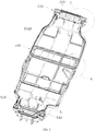
- an embodiment of the present invention provides an air supply system for a whole vehicle, mounted on an electric vehicle having a vehicle frame 5300 and configured for providing a plurality of air supply ports.
- the air supply system for the whole vehicle comprises a first air source device 501 and a second air source device 501 each having an air inlet 5011 and an air outlet 5022, a control valve 502 having an input port and a plurality of output ports (5022, 5023, 5024) and configured for switching an air flow direction, a controller (not shown in the figures) configured for transmitting an electric signal to the control valve 502 or the second air source device 501 so as to switch a operating state, and a plurality of pipelines 503 each having a start end and an tail end.
- the controller takes control of various electric equipments in the electric vehicle using a vehicle-mounted control computer system.
- the start end of each pipeline 503 is an inlet that allows a fluid to enter the pipeline 503, and the tail end of the pipeline 503 is an outlet that exhausts the fluid from the pipeline 503.
- the first air source device 501, the control valve 502 and the pipelines 503 constitute a first type of air supply system 5100, the air outlet 5012 of the first air source device 501 and the input port 5021 of the control valve 502 are connected together though one pipeline 503.
- the start ends of the plurality of pipelines 503 are correspondingly connected with the plurality of output ports (5022, 5023, 5024) of the control valve 502 one by one, and the tail ends of the plurality of pipelines 503 form the plurality of air supply ports.
- the controller is electrically connected to the control valve 502 and can switch the air flow direction that flows through the control valve 502 so as to achieve a control of opening or closing of various output ports of the respective control valve 502.
- the air enters from the air inlet 5011 of the first air source device 501 and is exhausted from the air outlet 5012 of the first air source device 5012 and then passes through the control valve 502.
- the control valve 502 works under the control of the electronic signal of the controller, the tail ends of the pipelines connected with the output ports of the control valve 502 form a plurality of air supply ports, and the venting of the plurality of air supply ports is controllable.
- the plurality of air supply ports provided by the first type of air supply system 5100 work independently.
- the second air source device 501 and the pipelines 503 constitute the second type of air supply system 5200, a start end of one pipeline 503 is connected with the air outlet 5012 of the second air source device 501, and the tail end of the pipeline 503 forms a node, and the node is respectively connected in series with a plurality of pipelines 503.
- the node refers to a cross point formed by intersection of a plurality of pipelines or other components that can form a fluid passageway.
- the controller is electrically connected with the second air source device 501, and can achieve a control of opening or closing of the second air source device 501.
- the controller transmits an "opening" electric signal to the second air source device 501, and the second air source device 501 operates, air enters from the air inlet 5011 of the second air source device 501 and is vented out from the air outlet 5012 of the second air source device 501.
- the tail ends of the pipelines connected with the air outlet 5012 of the second air source device 501 form a plurality of air supply ports.
- the controller transmits a "closing" electric signal to the second air source device 501, the second air source device doesn't operate, and the tail ends of the pipelines will not provide air.
- the plurality of air supply ports provided by the second type of air supply system 5200 work simultaneously.
- the first type of air supply system 5100 and the second type of air supply system 5200 are configured appropriately on the electric vehicle and are controlled by a single controller, which is regarded as a proposal with optimal configuration which can not only meet the requirement of multi-position and controllable air supply, but also achieve an effect of small space occupation and low power consumption.
- the first air source device 501, the control valve 502 and the plurality of pipelines 503 constitute the first type of air supply system 5100
- the first type of air supply system 5100 has a plurality of air passages, each of the air passages provides an air supply port respectively, and the air inlet is arranged at a position of the electric vehicle where an air supply needs to be provided.
- the controller can achieve a switching of operating states of the control valve 502, and take control of opening or closing of a plurality of air passages, thereby achieving a multi-position and controllable air supply effect.
- the second air source device 501 and a plurality of pipelines 503 constitute the second type of air supply system 5200.
- the second type of air supply system 5200 also has a plurality of air passages, and each of the air passages provides an air supply port respectively.
- the air supply port is arranged at a position of the electric vehicle where an air supply needs to be provided; moreover, the controller can achieve a switching of operating states of the second air source device 501, and take control of opening or closing of the plurality of air passages, thereby achieving a controllable air supply effect.
- positions of a pure electric vehicle where air supplies are provided comprise positions of heat dissipation of electric motors, sealing of cabin doors, safety air cushions, air springs, and so on.
- the first type of air supply system 5100 and the second type of air supply system 5200 are arranged appropriately on the electric vehicle, such that the multi-position and controllable air supply effect can be achieved.
- the first type of air supply system 5100 is divided into a first air supply sub system 510 mounted on a front part of the vehicle frame 5300, a second air supply sub system 520 mounted on a rear part of the vehicle frame 5300 and a third air supply sub system 530 mounted on a middle part of the vehicle frame 5300;
- the second type of air supply system 5200 is divided into a fourth air supply sub system 510 mounted on the front part of the vehicle frame 5300 and a fifth air supply sub system 550 mounted on the rear part of the vehicle frame 5300.
- the first air supply sub system 510, the second air supply sub system 520, the third air supply sub system 530, the fourth air supply sub system 540 and the fifth air supply sub system 550 are all controlled by the controller.
- the first air supply sub system 510 is configured for air supply and heart dissipation of hub motors and steering motors arranged on two sides of the front part of the electric vehicle, air supply of a collision air cushion of a battery at the front part, and air supply of a canopy
- the second air supply sub system 520 is configured for air supply and heart dissipation of hub motors and steering motors arranged on two sides of the rear part of the electric vehicle, air supply of a collision air cushion of a battery at the rear part
- the third air supply sub system 530 is configured for sealing and providing air supply for a front cabin door and a back cabin door, aspirating of power battery plug connectors and air supply of the air cushion.
- the fourth air supply sub system 540 and the fifth air supply sub system 550 are configured for air supply of air springs on the front cabin door and the back cabin door of the electric vehicle. These air supply sub systems are all controlled by a single controller, in this way, the air supply system for the whole vehicle can be much better in manipulation and practicability, and various air supply requirements from a user of an electric vehicle can be satisfied. These air supply sub systems are arranged at different positions of the vehicle frame 5300, thereby complying with a principle of proximity and reducing a space occupation.
- the first air supply sub system 510 comprises one first air source device 501, one control valve 502 and a plurality of pipelines 503.
- the first air supply sub system 510 has four air supply ports (5a, 5b, 5c, 5d), the output ports of the control valve 502 are divided into a first output port 5022, a second output port 5022 and a third output port 5023, the first output port 5022 of the control valve 502 is communicated with two air supply ports 5a and 5b (which are configured for air supply and heat dissipation of the hub motors and steering motors arranged at two sides of the front part of the electric vehicle) in the four air supply ports, air exhausted from the first output port 5022 of the control valve 502 flows towards a node along a pipeline 503, and further flows towards corresponding air supply port 5a and 5b along two pipelines 503 from the node.
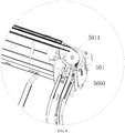
- each of the air supply ports 5a and 5b is perpendicular to a flat surface of the vehicle frame 5300, that is, the axial direction of each of the air supply ports 5a and 5b is parallel with an axial direction of each of the steering motors 5600, which allows air vented from the air supply ports 5a and 5b to flow into the hub motors and the steering motors 5600, thereby finishing heat dissipation of the hub motors and the steering motors 5600 at two sides of the front part of the electric vehicle; moreover, the second output port 5023 and the third output port 5024 of the control valve 502 are communicated with the other two air supply ports 5c and 5d (configured for providing air supply for the collision air cushion of the battery at the front part, and a canopy) of the four air supply ports, the second output port 5023 is connected with the start end of a pipeline and the tail end of the pipeline forms the air supply port 5c, the third output port 5024 is connected with the start end of another pipeline and the tail end of the pipeline forms
- the second air supply sub system 520 comprises one first air source device 501, two control valves 502 and a plurality of pipelines 503, the second air supply sub system 520 has three air support ports (5e, 5f, 5g), the output ports of the control valve 502 are divided into a first output port 5022 and a second output port 5023, two first output ports 5022 of the two control valves 502 are communicated with the two air supply ports 5e and 5f (configured for air supply and heat dissipation of hub motors and steering motors arranged at two sides of the rear part of the electric vehicle) in the three air supply ports respectively, air vented out from the first output port 5022 of the control valve 502 flows towards the air support port 5e and 5f along the pipelines 503.
- the axial direction of the air supply ports 5e and 5f are perpendicular to the flat surface of the vehicle frame 5300, that is, the axial direction of the air supply ports 5e and 5f are parallel to the axial direction of the steering motors, which allows the air vented from the air supply ports 5e and 5f to flow into the hub motors and the steering motors, thereby finishing the heat dissipation of the hub motors and the steering motors arranged at two sides of the rear part of the electric vehicle.
- the output ports 5023 of the two control valves 502 are communicated with each other and are further communicated with the other two air supply port 5g (configured for providing air supply for the collision air cushion of the battery at the rear of the electric vehicle) of the three air supply ports, and the air vented from the output ports 5023 of the two control valves 502 flows toward a node together along one pipeline 503 respectively, and further flow toward the air supply port 5g along another pipeline from the node.
- This configuration can effectively ensure a normal operation of the air supply port 5g configured for providing air supply for the collision air cushion of the battery at the rear part of the electric vehicle; once a first air source device 501 operates, the air supply for the collision air cushion of the battery at the rear part of the electric vehicle can be finished.
- the third air supply sub system 530 comprises two first air source devices 501, two control valves 502 and a plurality of pipelines 503.
- the third air supply sub system 530 has six air supply ports (5h, 5i, 5j, 5k, 5l, 5m), and the output ports of the control valve 502 are divided into a first output port 5022, a second output port 5023 and a third output port 5024, the first output ports 5022 of the two control valves 502 are communicated with the two air supply ports 5h and 5i (configured for providing an air cushion 5400 with air supply) of the six air supply ports respectively; moreover, the output ports 5023 of the two control valves 502 are communicated with another two air supply ports 5j and 5k (configured for providing the front cabin door and the rear cabin door of the electric vehicle with sealing and air supply) of the six air supply ports, the air supply ports 5j and 5k inflate a chamber of an air bag sealing strip 5500 so as to implement sealing of the front cabin door and the rear cabin door; more
- a plurality of chambers that extend along a profile of the vehicle frame 5300 are formed in an inner side of the vehicle frame 5300, and one of the chambers 5301 is served as the first air duct 504.
- the chambers 5301 arranged in the vehicle frame 5300 have different functionalities, such as, receiving electric cables, working as air passages having different functions, allowing brake oil to flow, and so on. This structure can make use of the space of the electric vehicle effectively and achieve an air duct effect without adding pipelines additionally.
- the chambers 5301 extend along the profile of the vehicle frame 5300, the profile of the vehicle frame 5300 is loop-shaped, the first air duct 504 is also loop-shaped.
- a cross section of each of the chambers 5301 is substantially rectangle-shaped, so that it is convenient for the vehicle frame 5300 to be processed and molded.
- the first air source device 501 is a high pressure blower
- the control valve 502 is a pneumatic reversing valve.
- the high pressure blower is a mechanical device configured for increasing air pressure via input mechanical energy and exhausted gas
- the pneumatic reversing valve plays the role of receiving an electric signal from the controller so as to switch an air flow direction. Applying a combination of the high pressure blower and the pneumatic reversing valve can meet the requirement of independent and multi-position air supply.
- the axial directions of the high pressure blowers in the second air supply sub system 520 and the third air supply sub system 530 are perpendicular to the flat surface of the vehicle frame 5300, which enables the high pressure blower to be mounted in the electric vehicle in a smaller room and in a vertical direction.
- the high pressure blowers and the pneumatic reversing valves are divided into two groups and are arranged at two sides of the middle portion of the electric vehicle respectively.
- the fourth air supply sub system 540 comprises one second air supply device 501 and a plurality of pipelines 503.
- the node is connected in series with a plurality of second air ducts 505, each of the second air ducts 505 is connected with one pipeline 503 respectively, and the tail ends of the pipeline 503 are served as the air supply ports 5n and 5o (configured for providing air supplies for air springs of the front cabin door and the rear cabin door of the electric vehicle).
- a plurality of chambers 5301 extending along the profile of the vehicle frame 5300 are formed in the inner side of the vehicle frame 5300, and one of the chambers 5301 is served as the second air duct 505.
- the fourth air supply sub system 540 is controlled by the controller and is configured for providing air supplies for the lifting of the air springs of the front cabin door and the rear cabin door, and can adjust a speed of the lifting and take control of opening and closing of the front cabin door of the electric vehicle by cooperating with a hinge mechanism.
- the air springs are free style air springs which are mainly configured for support and have a shortest position and a longest position merely, and can't stop on their own in a moving process.
- the node is connected in series with two second air ducts 505, each of the two second air ducts 505 is connected to one pipeline 503 respectively, and the tail ends of the pipelines 503 are served as two air supply ports 5n and 5o configured for inflating or aspirating the two air springs of the front cabin door of the electric vehicle simultaneously, thereby achieving the control of opening and closing of the front cabin door.
- the fifth air supply sub system 550 comprises one second air source device 501 and the plurality of pipelines 503.
- the node is connected in series with a plurality of third air ducts 506, each of the air ducts 506 is connected with a pipeline 503 respectively, and the tail ends of the pipelines 503 are served as the air supply ports 5p and 5q (configured for providing air supplies for the air springs of the rear cabin door of the electric vehicle).
- a plurality of chambers 5301 extending along the profile of the vehicle frame 5300 are formed in an inner side of the vehicle frame 5300 forms, and one of the chambers 5301 is served as the third air duct 506.
- the fifth air supply sub system 550 which is controlled by the controller and is configured for providing air supplies for the lifting of the air springs of the rear cabin door, can adjust a speed of lifting and take control of opening and closing of the front cabin door of the electric vehicle by cooperating with a hinge mechanism.
- the node is connected in series with two third air ducts 506, each of the two third air ducts 506 is connected to one pipeline 503 respectively, and the tail ends of the pipeline 503 form two air supply ports 5p and 5q configured for inflating or aspirating the two air springs of the front cabin door of the electric vehicle simultaneously, thereby achieving the control of opening and closing of the rear cabin door.
- the fourth air supply sub system 540 and the fifth air supply sub system 550 can work synchronously or asynchronously, thereby achieving different open modes of the cabin doors of the electric vehicle.
- the second air source device 501 is a high pressure air pump which can exhaust gas from an enclosed space or inhaling gas into the enclosed space, in other words, inflating and aspirating.
- the high pressure air pump is controlled by the controller and is configured to take control of inflating and aspirating of the air springs, thereby achieving a control of opening and closing of the front cabin door and the rear cabin door of the electric vehicle.
Landscapes
- Engineering & Computer Science (AREA)
- Mechanical Engineering (AREA)
- Chemical & Material Sciences (AREA)
- Transportation (AREA)
- Combustion & Propulsion (AREA)
- Physics & Mathematics (AREA)
- Thermal Sciences (AREA)
- General Engineering & Computer Science (AREA)
- Fluid Mechanics (AREA)
- Analytical Chemistry (AREA)
- Electric Propulsion And Braking For Vehicles (AREA)
- Multiple-Way Valves (AREA)
- Cooling, Air Intake And Gas Exhaust, And Fuel Tank Arrangements In Propulsion Units (AREA)
- Arrangement Or Mounting Of Propulsion Units For Vehicles (AREA)
- Fluid-Pressure Circuits (AREA)
- Vehicle Body Suspensions (AREA)
- Air-Conditioning For Vehicles (AREA)
Applications Claiming Priority (1)
| Application Number | Priority Date | Filing Date | Title |
|---|---|---|---|
| PCT/CN2014/074561 WO2015149289A1 (fr) | 2014-04-01 | 2014-04-01 | Système d'alimentation en air pour l'ensemble d'un véhicule |
Publications (3)
| Publication Number | Publication Date |
|---|---|
| EP3127728A1 true EP3127728A1 (fr) | 2017-02-08 |
| EP3127728A4 EP3127728A4 (fr) | 2017-12-20 |
| EP3127728B1 EP3127728B1 (fr) | 2020-06-03 |
Family
ID=54239273
Family Applications (1)
| Application Number | Title | Priority Date | Filing Date |
|---|---|---|---|
| EP14888273.1A Not-in-force EP3127728B1 (fr) | 2014-04-01 | 2014-04-01 | Système d'alimentation d'air pour un véhicule |
Country Status (7)
| Country | Link |
|---|---|
| US (1) | US10906588B2 (fr) |
| EP (1) | EP3127728B1 (fr) |
| JP (1) | JP6411543B2 (fr) |
| KR (1) | KR102167833B1 (fr) |
| CN (1) | CN106103148B (fr) |
| ES (1) | ES2811277T3 (fr) |
| WO (1) | WO2015149289A1 (fr) |
Cited By (1)
| Publication number | Priority date | Publication date | Assignee | Title |
|---|---|---|---|---|
| CN109177693A (zh) * | 2018-11-01 | 2019-01-11 | 珠海格力电器股份有限公司 | 客车 |
Families Citing this family (1)
| Publication number | Priority date | Publication date | Assignee | Title |
|---|---|---|---|---|
| KR102869053B1 (ko) * | 2020-08-18 | 2025-10-10 | 현대자동차 주식회사 | 차량의 하부 차체 구조 |
Family Cites Families (27)
| Publication number | Priority date | Publication date | Assignee | Title |
|---|---|---|---|---|
| US1002822A (en) * | 1909-10-23 | 1911-09-12 | Irving Cowles | Pneumatic cushioning device. |
| GB1254593A (en) * | 1969-02-11 | 1971-11-24 | Tatra Np | Improvements in or relating to heating and ventilating systems for vehicles |
| US3951222A (en) * | 1974-12-23 | 1976-04-20 | Fletcher Maurice C | Lightweight automobile |
| JPS6085007A (ja) * | 1983-10-17 | 1985-05-14 | Toyota Motor Corp | 車輌用車高調整装置 |
| US4640331A (en) * | 1984-06-04 | 1987-02-03 | Eaton Corporation | Central tire inflation system |
| JPS61188213A (ja) * | 1985-02-15 | 1986-08-21 | Hitachi Ltd | 自動車用空気調和装置 |
| JP2944148B2 (ja) * | 1990-06-07 | 1999-08-30 | マツダ株式会社 | 車両のサスペンション装置 |
| US5684698A (en) * | 1994-04-15 | 1997-11-04 | Kabushiki Kaisha Toyoda Jidoshokki Seisakusho | Vehicle attitude and average height control apparatus |
| JP3911076B2 (ja) * | 1997-10-13 | 2007-05-09 | サンデン株式会社 | 車両用冷房装置 |
| FR2775221B1 (fr) * | 1998-02-20 | 2000-05-26 | Renault | Dispositif d'aeration, de chauffage et de climatisation d'un habitacle d'un vehicule automobile |
| GB0108919D0 (en) * | 2001-04-10 | 2001-05-30 | Delphi Tech Inc | Vehicle roll control system |
| DE10164948A1 (de) * | 2001-12-11 | 2007-09-20 | Daimlerchrysler Ag | Verfahren zur Regelung der Luftmenge in einem Niveauregulierungssystem |
| US6851470B2 (en) * | 2002-05-23 | 2005-02-08 | International Truck Intellectual Property Company, Llc | Air mixing system for auxiliary vehicle HVAC units |
| CN2572261Y (zh) * | 2002-10-10 | 2003-09-10 | 沈阳航达机载设备公司 | 飞机地面空调车 |
| US7270346B2 (en) * | 2004-09-27 | 2007-09-18 | Oshkosh Truck Corporation | Vehicle frame |
| CN2830952Y (zh) * | 2005-02-21 | 2006-10-25 | 广州市新基业工业设备技术有限公司 | 一种新型风门可调节电控新风装置 |
| JP4650108B2 (ja) | 2005-06-01 | 2011-03-16 | 日産自動車株式会社 | 車両の強電系冷却装置 |
| FR2893537A1 (fr) * | 2005-11-21 | 2007-05-25 | Renault Sas | Dispositif de climatisation d'habitacle de vehicule automobile |
| JP2007182197A (ja) * | 2006-01-10 | 2007-07-19 | Toyota Motor Corp | 車高調整装置 |
| JP4901422B2 (ja) * | 2006-10-26 | 2012-03-21 | トヨタ自動車株式会社 | 車両に搭載された電気機器の冷却制御装置 |
| US7942427B2 (en) * | 2009-04-23 | 2011-05-17 | Arvinmeritor Technology, Llc | Air supply system for active air suspension |
| JP2012087742A (ja) * | 2010-10-21 | 2012-05-10 | Mitsubishi Fuso Truck & Bus Corp | エアドライヤ保護装置 |
| CN102452297B (zh) * | 2010-10-29 | 2014-07-09 | 杭州三花研究院有限公司 | 电动汽车及其热管理系统 |
| CN102353546A (zh) * | 2011-06-27 | 2012-02-15 | 黄志辉 | 试验台用风量风向均可调节的导风柜 |
| US8973688B2 (en) * | 2011-12-20 | 2015-03-10 | Caterpillar Paving Products Inc. | Suspension system and control method for track-propelled machines |
| CN202413815U (zh) * | 2012-01-10 | 2012-09-05 | 南车青岛四方机车车辆股份有限公司 | 高速轨道车辆废排装置 |
| WO2015149288A1 (fr) * | 2014-04-01 | 2015-10-08 | 深圳市智轮电动车驱动技术有限公司 | Véhicule électrique |
-
2014
- 2014-04-01 EP EP14888273.1A patent/EP3127728B1/fr not_active Not-in-force
- 2014-04-01 CN CN201480076943.0A patent/CN106103148B/zh not_active Expired - Fee Related
- 2014-04-01 US US15/300,445 patent/US10906588B2/en not_active Expired - Fee Related
- 2014-04-01 ES ES14888273T patent/ES2811277T3/es active Active
- 2014-04-01 WO PCT/CN2014/074561 patent/WO2015149289A1/fr not_active Ceased
- 2014-04-01 JP JP2016560752A patent/JP6411543B2/ja not_active Expired - Fee Related
- 2014-04-01 KR KR1020167028967A patent/KR102167833B1/ko not_active Expired - Fee Related
Cited By (1)
| Publication number | Priority date | Publication date | Assignee | Title |
|---|---|---|---|---|
| CN109177693A (zh) * | 2018-11-01 | 2019-01-11 | 珠海格力电器股份有限公司 | 客车 |
Also Published As
| Publication number | Publication date |
|---|---|
| KR102167833B1 (ko) | 2020-10-21 |
| US10906588B2 (en) | 2021-02-02 |
| ES2811277T3 (es) | 2021-03-11 |
| EP3127728B1 (fr) | 2020-06-03 |
| KR20160142317A (ko) | 2016-12-12 |
| WO2015149289A1 (fr) | 2015-10-08 |
| CN106103148A (zh) | 2016-11-09 |
| EP3127728A4 (fr) | 2017-12-20 |
| JP6411543B2 (ja) | 2018-10-24 |
| US20170120954A1 (en) | 2017-05-04 |
| CN106103148B (zh) | 2018-03-30 |
| JP2017512702A (ja) | 2017-05-25 |
Similar Documents
| Publication | Publication Date | Title |
|---|---|---|
| ES2868924T3 (es) | Vehículo eléctrico | |
| CN101954927B (zh) | 单动力源多系统工作的多负荷传感液压系统 | |
| EP3127728B1 (fr) | Système d'alimentation d'air pour un véhicule | |
| US10087925B2 (en) | Pneumatic distribution system using shared pump plenum | |
| JP6078606B1 (ja) | 自動車用空調装置 | |
| CN105443832A (zh) | 电磁气阀 | |
| US20150345437A1 (en) | Air flow control system of vehicle | |
| US11432995B2 (en) | Pneumatic massage | |
| CN108189827B (zh) | 组合式驻车阀和具有其的车辆 | |
| CN112977213A (zh) | 气动腰托的控制装置 | |
| CN113323937A (zh) | 一种阀岛 | |
| CN104385864A (zh) | 一种可调压式充放气回路系统及其充放气方法 | |
| US11279200B2 (en) | Motor vehicle wheelset anti-roll device with actuating means operated by a hydraulic control circuit | |
| CN209959601U (zh) | 一种双路可控电磁阀 | |
| US10731674B2 (en) | Method for forming hydraulic actuator hydraulic oil passage | |
| EP3325288B1 (fr) | Bloc de soupapes pour un système de gonflage de pneu central | |
| CN113561952A (zh) | 一种车辆的驻车制动系统及车辆 | |
| KR20250006433A (ko) | 차량용 시트의 공압 조절 장치 | |
| CN114802159A (zh) | 紧急阀 | |
| JP2011195063A (ja) | 車室構成部品冷却装置 | |
| CN111591097B (zh) | 一种ecas集成模块 | |
| CN216199324U (zh) | 一种真空发生器 | |
| CN216895931U (zh) | 一种快充型气阀 | |
| CN216868190U (zh) | 集成气路控制阀 | |
| CN202171040U (zh) | 助力二位三通双控阀 |
Legal Events
| Date | Code | Title | Description |
|---|---|---|---|
| STAA | Information on the status of an ep patent application or granted ep patent |
Free format text: STATUS: THE INTERNATIONAL PUBLICATION HAS BEEN MADE |
|
| PUAI | Public reference made under article 153(3) epc to a published international application that has entered the european phase |
Free format text: ORIGINAL CODE: 0009012 |
|
| STAA | Information on the status of an ep patent application or granted ep patent |
Free format text: STATUS: REQUEST FOR EXAMINATION WAS MADE |
|
| 17P | Request for examination filed |
Effective date: 20161028 |
|
| AK | Designated contracting states |
Kind code of ref document: A1 Designated state(s): AL AT BE BG CH CY CZ DE DK EE ES FI FR GB GR HR HU IE IS IT LI LT LU LV MC MK MT NL NO PL PT RO RS SE SI SK SM TR |
|
| AX | Request for extension of the european patent |
Extension state: BA ME |
|
| DAX | Request for extension of the european patent (deleted) | ||
| A4 | Supplementary search report drawn up and despatched |
Effective date: 20171122 |
|
| RIC1 | Information provided on ipc code assigned before grant |
Ipc: B61D 27/00 20060101ALI20171114BHEP Ipc: B60H 1/00 20060101AFI20171114BHEP Ipc: F24F 7/04 20060101ALI20171114BHEP |
|
| RAP1 | Party data changed (applicant data changed or rights of an application transferred) |
Owner name: GUANGDONG HUA'CHAN RESEARCH INSTITUTE OF INTELLIGE |
|
| GRAP | Despatch of communication of intention to grant a patent |
Free format text: ORIGINAL CODE: EPIDOSNIGR1 |
|
| STAA | Information on the status of an ep patent application or granted ep patent |
Free format text: STATUS: GRANT OF PATENT IS INTENDED |
|
| INTG | Intention to grant announced |
Effective date: 20200121 |
|
| GRAS | Grant fee paid |
Free format text: ORIGINAL CODE: EPIDOSNIGR3 |
|
| GRAA | (expected) grant |
Free format text: ORIGINAL CODE: 0009210 |
|
| STAA | Information on the status of an ep patent application or granted ep patent |
Free format text: STATUS: THE PATENT HAS BEEN GRANTED |
|
| AK | Designated contracting states |
Kind code of ref document: B1 Designated state(s): AL AT BE BG CH CY CZ DE DK EE ES FI FR GB GR HR HU IE IS IT LI LT LU LV MC MK MT NL NO PL PT RO RS SE SI SK SM TR |
|
| REG | Reference to a national code |
Ref country code: GB Ref legal event code: FG4D |
|
| REG | Reference to a national code |
Ref country code: CH Ref legal event code: EP Ref country code: AT Ref legal event code: REF Ref document number: 1276666 Country of ref document: AT Kind code of ref document: T Effective date: 20200615 |
|
| REG | Reference to a national code |
Ref country code: DE Ref legal event code: R096 Ref document number: 602014066371 Country of ref document: DE |
|
| REG | Reference to a national code |
Ref country code: CH Ref legal event code: NV Representative=s name: DENNEMEYER AG, CH |
|
| REG | Reference to a national code |
Ref country code: NL Ref legal event code: FP |
|
| REG | Reference to a national code |
Ref country code: FI Ref legal event code: FGE |
|
| REG | Reference to a national code |
Ref country code: LT Ref legal event code: MG4D |
|
| PG25 | Lapsed in a contracting state [announced via postgrant information from national office to epo] |
Ref country code: SE Free format text: LAPSE BECAUSE OF FAILURE TO SUBMIT A TRANSLATION OF THE DESCRIPTION OR TO PAY THE FEE WITHIN THE PRESCRIBED TIME-LIMIT Effective date: 20200603 Ref country code: NO Free format text: LAPSE BECAUSE OF FAILURE TO SUBMIT A TRANSLATION OF THE DESCRIPTION OR TO PAY THE FEE WITHIN THE PRESCRIBED TIME-LIMIT Effective date: 20200903 Ref country code: GR Free format text: LAPSE BECAUSE OF FAILURE TO SUBMIT A TRANSLATION OF THE DESCRIPTION OR TO PAY THE FEE WITHIN THE PRESCRIBED TIME-LIMIT Effective date: 20200904 Ref country code: LT Free format text: LAPSE BECAUSE OF FAILURE TO SUBMIT A TRANSLATION OF THE DESCRIPTION OR TO PAY THE FEE WITHIN THE PRESCRIBED TIME-LIMIT Effective date: 20200603 |
|
| PG25 | Lapsed in a contracting state [announced via postgrant information from national office to epo] |
Ref country code: RS Free format text: LAPSE BECAUSE OF FAILURE TO SUBMIT A TRANSLATION OF THE DESCRIPTION OR TO PAY THE FEE WITHIN THE PRESCRIBED TIME-LIMIT Effective date: 20200603 Ref country code: BG Free format text: LAPSE BECAUSE OF FAILURE TO SUBMIT A TRANSLATION OF THE DESCRIPTION OR TO PAY THE FEE WITHIN THE PRESCRIBED TIME-LIMIT Effective date: 20200903 Ref country code: LV Free format text: LAPSE BECAUSE OF FAILURE TO SUBMIT A TRANSLATION OF THE DESCRIPTION OR TO PAY THE FEE WITHIN THE PRESCRIBED TIME-LIMIT Effective date: 20200603 Ref country code: HR Free format text: LAPSE BECAUSE OF FAILURE TO SUBMIT A TRANSLATION OF THE DESCRIPTION OR TO PAY THE FEE WITHIN THE PRESCRIBED TIME-LIMIT Effective date: 20200603 |
|
| REG | Reference to a national code |
Ref country code: AT Ref legal event code: MK05 Ref document number: 1276666 Country of ref document: AT Kind code of ref document: T Effective date: 20200603 |
|
| PG25 | Lapsed in a contracting state [announced via postgrant information from national office to epo] |
Ref country code: AL Free format text: LAPSE BECAUSE OF FAILURE TO SUBMIT A TRANSLATION OF THE DESCRIPTION OR TO PAY THE FEE WITHIN THE PRESCRIBED TIME-LIMIT Effective date: 20200603 |
|
| PG25 | Lapsed in a contracting state [announced via postgrant information from national office to epo] |
Ref country code: RO Free format text: LAPSE BECAUSE OF FAILURE TO SUBMIT A TRANSLATION OF THE DESCRIPTION OR TO PAY THE FEE WITHIN THE PRESCRIBED TIME-LIMIT Effective date: 20200603 Ref country code: PT Free format text: LAPSE BECAUSE OF FAILURE TO SUBMIT A TRANSLATION OF THE DESCRIPTION OR TO PAY THE FEE WITHIN THE PRESCRIBED TIME-LIMIT Effective date: 20201006 Ref country code: EE Free format text: LAPSE BECAUSE OF FAILURE TO SUBMIT A TRANSLATION OF THE DESCRIPTION OR TO PAY THE FEE WITHIN THE PRESCRIBED TIME-LIMIT Effective date: 20200603 Ref country code: SM Free format text: LAPSE BECAUSE OF FAILURE TO SUBMIT A TRANSLATION OF THE DESCRIPTION OR TO PAY THE FEE WITHIN THE PRESCRIBED TIME-LIMIT Effective date: 20200603 Ref country code: AT Free format text: LAPSE BECAUSE OF FAILURE TO SUBMIT A TRANSLATION OF THE DESCRIPTION OR TO PAY THE FEE WITHIN THE PRESCRIBED TIME-LIMIT Effective date: 20200603 Ref country code: CZ Free format text: LAPSE BECAUSE OF FAILURE TO SUBMIT A TRANSLATION OF THE DESCRIPTION OR TO PAY THE FEE WITHIN THE PRESCRIBED TIME-LIMIT Effective date: 20200603 |
|
| PG25 | Lapsed in a contracting state [announced via postgrant information from national office to epo] |
Ref country code: PL Free format text: LAPSE BECAUSE OF FAILURE TO SUBMIT A TRANSLATION OF THE DESCRIPTION OR TO PAY THE FEE WITHIN THE PRESCRIBED TIME-LIMIT Effective date: 20200603 Ref country code: SK Free format text: LAPSE BECAUSE OF FAILURE TO SUBMIT A TRANSLATION OF THE DESCRIPTION OR TO PAY THE FEE WITHIN THE PRESCRIBED TIME-LIMIT Effective date: 20200603 Ref country code: IS Free format text: LAPSE BECAUSE OF FAILURE TO SUBMIT A TRANSLATION OF THE DESCRIPTION OR TO PAY THE FEE WITHIN THE PRESCRIBED TIME-LIMIT Effective date: 20201003 |
|
| REG | Reference to a national code |
Ref country code: DE Ref legal event code: R097 Ref document number: 602014066371 Country of ref document: DE |
|
| REG | Reference to a national code |
Ref country code: ES Ref legal event code: FG2A Ref document number: 2811277 Country of ref document: ES Kind code of ref document: T3 Effective date: 20210311 |
|
| PLBE | No opposition filed within time limit |
Free format text: ORIGINAL CODE: 0009261 |
|
| STAA | Information on the status of an ep patent application or granted ep patent |
Free format text: STATUS: NO OPPOSITION FILED WITHIN TIME LIMIT |
|
| PG25 | Lapsed in a contracting state [announced via postgrant information from national office to epo] |
Ref country code: DK Free format text: LAPSE BECAUSE OF FAILURE TO SUBMIT A TRANSLATION OF THE DESCRIPTION OR TO PAY THE FEE WITHIN THE PRESCRIBED TIME-LIMIT Effective date: 20200603 |
|
| 26N | No opposition filed |
Effective date: 20210304 |
|
| PG25 | Lapsed in a contracting state [announced via postgrant information from national office to epo] |
Ref country code: SI Free format text: LAPSE BECAUSE OF FAILURE TO SUBMIT A TRANSLATION OF THE DESCRIPTION OR TO PAY THE FEE WITHIN THE PRESCRIBED TIME-LIMIT Effective date: 20200603 |
|
| PGFP | Annual fee paid to national office [announced via postgrant information from national office to epo] |
Ref country code: TR Payment date: 20210330 Year of fee payment: 8 |
|
| PGFP | Annual fee paid to national office [announced via postgrant information from national office to epo] |
Ref country code: FR Payment date: 20210423 Year of fee payment: 8 Ref country code: DE Payment date: 20210420 Year of fee payment: 8 Ref country code: IT Payment date: 20210427 Year of fee payment: 8 Ref country code: FI Payment date: 20210421 Year of fee payment: 8 |
|
| PGFP | Annual fee paid to national office [announced via postgrant information from national office to epo] |
Ref country code: BE Payment date: 20210420 Year of fee payment: 8 Ref country code: GB Payment date: 20210422 Year of fee payment: 8 Ref country code: CH Payment date: 20210420 Year of fee payment: 8 Ref country code: ES Payment date: 20210621 Year of fee payment: 8 |
|
| PGFP | Annual fee paid to national office [announced via postgrant information from national office to epo] |
Ref country code: NL Payment date: 20210420 Year of fee payment: 8 |
|
| PG25 | Lapsed in a contracting state [announced via postgrant information from national office to epo] |
Ref country code: MC Free format text: LAPSE BECAUSE OF FAILURE TO SUBMIT A TRANSLATION OF THE DESCRIPTION OR TO PAY THE FEE WITHIN THE PRESCRIBED TIME-LIMIT Effective date: 20200603 |
|
| PG25 | Lapsed in a contracting state [announced via postgrant information from national office to epo] |
Ref country code: LU Free format text: LAPSE BECAUSE OF NON-PAYMENT OF DUE FEES Effective date: 20210401 |
|
| PG25 | Lapsed in a contracting state [announced via postgrant information from national office to epo] |
Ref country code: IE Free format text: LAPSE BECAUSE OF NON-PAYMENT OF DUE FEES Effective date: 20210401 |
|
| PG25 | Lapsed in a contracting state [announced via postgrant information from national office to epo] |
Ref country code: IS Free format text: LAPSE BECAUSE OF FAILURE TO SUBMIT A TRANSLATION OF THE DESCRIPTION OR TO PAY THE FEE WITHIN THE PRESCRIBED TIME-LIMIT Effective date: 20201003 |
|
| REG | Reference to a national code |
Ref country code: DE Ref legal event code: R119 Ref document number: 602014066371 Country of ref document: DE |
|
| REG | Reference to a national code |
Ref country code: CH Ref legal event code: PL |
|
| REG | Reference to a national code |
Ref country code: NL Ref legal event code: MM Effective date: 20220501 |
|
| GBPC | Gb: european patent ceased through non-payment of renewal fee |
Effective date: 20220401 |
|
| REG | Reference to a national code |
Ref country code: BE Ref legal event code: MM Effective date: 20220430 |
|
| PG25 | Lapsed in a contracting state [announced via postgrant information from national office to epo] |
Ref country code: NL Free format text: LAPSE BECAUSE OF NON-PAYMENT OF DUE FEES Effective date: 20220501 Ref country code: LI Free format text: LAPSE BECAUSE OF NON-PAYMENT OF DUE FEES Effective date: 20220430 Ref country code: GB Free format text: LAPSE BECAUSE OF NON-PAYMENT OF DUE FEES Effective date: 20220401 Ref country code: FR Free format text: LAPSE BECAUSE OF NON-PAYMENT OF DUE FEES Effective date: 20220430 Ref country code: FI Free format text: LAPSE BECAUSE OF NON-PAYMENT OF DUE FEES Effective date: 20220401 Ref country code: DE Free format text: LAPSE BECAUSE OF NON-PAYMENT OF DUE FEES Effective date: 20221103 Ref country code: CH Free format text: LAPSE BECAUSE OF NON-PAYMENT OF DUE FEES Effective date: 20220430 |
|
| PG25 | Lapsed in a contracting state [announced via postgrant information from national office to epo] |
Ref country code: BE Free format text: LAPSE BECAUSE OF NON-PAYMENT OF DUE FEES Effective date: 20220430 |
|
| PG25 | Lapsed in a contracting state [announced via postgrant information from national office to epo] |
Ref country code: IT Free format text: LAPSE BECAUSE OF NON-PAYMENT OF DUE FEES Effective date: 20220401 Ref country code: HU Free format text: LAPSE BECAUSE OF FAILURE TO SUBMIT A TRANSLATION OF THE DESCRIPTION OR TO PAY THE FEE WITHIN THE PRESCRIBED TIME-LIMIT; INVALID AB INITIO Effective date: 20140401 |
|
| REG | Reference to a national code |
Ref country code: ES Ref legal event code: FD2A Effective date: 20230606 |
|
| PG25 | Lapsed in a contracting state [announced via postgrant information from national office to epo] |
Ref country code: CY Free format text: LAPSE BECAUSE OF FAILURE TO SUBMIT A TRANSLATION OF THE DESCRIPTION OR TO PAY THE FEE WITHIN THE PRESCRIBED TIME-LIMIT Effective date: 20200603 |
|
| PG25 | Lapsed in a contracting state [announced via postgrant information from national office to epo] |
Ref country code: ES Free format text: LAPSE BECAUSE OF NON-PAYMENT OF DUE FEES Effective date: 20220402 |
|
| PG25 | Lapsed in a contracting state [announced via postgrant information from national office to epo] |
Ref country code: MK Free format text: LAPSE BECAUSE OF FAILURE TO SUBMIT A TRANSLATION OF THE DESCRIPTION OR TO PAY THE FEE WITHIN THE PRESCRIBED TIME-LIMIT Effective date: 20200603 |
|
| PG25 | Lapsed in a contracting state [announced via postgrant information from national office to epo] |
Ref country code: TR Free format text: LAPSE BECAUSE OF NON-PAYMENT OF DUE FEES Effective date: 20220401 Ref country code: MT Free format text: LAPSE BECAUSE OF FAILURE TO SUBMIT A TRANSLATION OF THE DESCRIPTION OR TO PAY THE FEE WITHIN THE PRESCRIBED TIME-LIMIT Effective date: 20200603 |