EP3127732B1 - Système d'auvent contre la pluie et véhicule électrique en étant doté - Google Patents
Système d'auvent contre la pluie et véhicule électrique en étant doté Download PDFInfo
- Publication number
- EP3127732B1 EP3127732B1 EP14887870.5A EP14887870A EP3127732B1 EP 3127732 B1 EP3127732 B1 EP 3127732B1 EP 14887870 A EP14887870 A EP 14887870A EP 3127732 B1 EP3127732 B1 EP 3127732B1
- Authority
- EP
- European Patent Office
- Prior art keywords
- air hose
- awning
- guide
- roller
- rain
- Prior art date
- Legal status (The legal status is an assumption and is not a legal conclusion. Google has not performed a legal analysis and makes no representation as to the accuracy of the status listed.)
- Active
Links
- 239000004744 fabric Substances 0.000 claims description 103
- 230000033001 locomotion Effects 0.000 claims description 12
- 238000005096 rolling process Methods 0.000 claims description 10
- 230000005540 biological transmission Effects 0.000 claims description 8
- 230000007246 mechanism Effects 0.000 description 10
- 238000000034 method Methods 0.000 description 3
- 239000003208 petroleum Substances 0.000 description 3
- 230000008569 process Effects 0.000 description 3
- 230000001681 protective effect Effects 0.000 description 3
- 230000009471 action Effects 0.000 description 2
- 230000000875 corresponding effect Effects 0.000 description 2
- 230000000694 effects Effects 0.000 description 2
- 230000003796 beauty Effects 0.000 description 1
- 230000003749 cleanliness Effects 0.000 description 1
- 230000002079 cooperative effect Effects 0.000 description 1
- 230000007812 deficiency Effects 0.000 description 1
- 230000007613 environmental effect Effects 0.000 description 1
- 230000001737 promoting effect Effects 0.000 description 1
- 238000011160 research Methods 0.000 description 1
- 230000004044 response Effects 0.000 description 1
- 230000000087 stabilizing effect Effects 0.000 description 1
Images



Classifications
-
- B—PERFORMING OPERATIONS; TRANSPORTING
- B60—VEHICLES IN GENERAL
- B60J—WINDOWS, WINDSCREENS, NON-FIXED ROOFS, DOORS, OR SIMILAR DEVICES FOR VEHICLES; REMOVABLE EXTERNAL PROTECTIVE COVERINGS SPECIALLY ADAPTED FOR VEHICLES
- B60J5/00—Doors
- B60J5/04—Doors arranged at the vehicle sides
- B60J5/0493—Appurtenances
- B60J5/0494—Rain covers deployed upon opening door
-
- B—PERFORMING OPERATIONS; TRANSPORTING
- B60—VEHICLES IN GENERAL
- B60R—VEHICLES, VEHICLE FITTINGS, OR VEHICLE PARTS, NOT OTHERWISE PROVIDED FOR
- B60R16/00—Electric or fluid circuits specially adapted for vehicles and not otherwise provided for; Arrangement of elements of electric or fluid circuits specially adapted for vehicles and not otherwise provided for
- B60R16/08—Electric or fluid circuits specially adapted for vehicles and not otherwise provided for; Arrangement of elements of electric or fluid circuits specially adapted for vehicles and not otherwise provided for fluid
-
- F—MECHANICAL ENGINEERING; LIGHTING; HEATING; WEAPONS; BLASTING
- F16—ENGINEERING ELEMENTS AND UNITS; GENERAL MEASURES FOR PRODUCING AND MAINTAINING EFFECTIVE FUNCTIONING OF MACHINES OR INSTALLATIONS; THERMAL INSULATION IN GENERAL
- F16H—GEARING
- F16H7/00—Gearings for conveying rotary motion by endless flexible members
- F16H7/02—Gearings for conveying rotary motion by endless flexible members with belts; with V-belts
-
- B—PERFORMING OPERATIONS; TRANSPORTING
- B60—VEHICLES IN GENERAL
- B60Y—INDEXING SCHEME RELATING TO ASPECTS CROSS-CUTTING VEHICLE TECHNOLOGY
- B60Y2200/00—Type of vehicle
- B60Y2200/90—Vehicles comprising electric prime movers
- B60Y2200/91—Electric vehicles
-
- B—PERFORMING OPERATIONS; TRANSPORTING
- B60—VEHICLES IN GENERAL
- B60Y—INDEXING SCHEME RELATING TO ASPECTS CROSS-CUTTING VEHICLE TECHNOLOGY
- B60Y2400/00—Special features of vehicle units
- B60Y2400/40—Actuators for moving a controlled member
- B60Y2400/41—Mechanical transmissions for actuators
-
- B—PERFORMING OPERATIONS; TRANSPORTING
- B60—VEHICLES IN GENERAL
- B60Y—INDEXING SCHEME RELATING TO ASPECTS CROSS-CUTTING VEHICLE TECHNOLOGY
- B60Y2400/00—Special features of vehicle units
- B60Y2400/40—Actuators for moving a controlled member
- B60Y2400/418—Power assistance, e.g. servo-motors
- B60Y2400/4187—Servo-motors, e.g. electric or fluidic with feedback control
Definitions
- the present application relates to the technical field of vehicle rain-proof systems, and more particularly, relates to a stretchable rain awning system and an electric vehicle having the same.
- a head cover of the electric vehicle can be used to provide wind-proof and rain-proof function; with respect to the vehicle having the door opened upwardly and outwardly, when it is driven normally, the door of the vehicle can provide a rain-proof function, however, after the door is opened upwardly, the door cannot provide the rain-proof function, an interior of the vehicle is prone to get wet, which is not conducive to the normal driving of the electric vehicle.
- US 7,086,684 discloses a protective awning including a base frame, which may be fastened to a vehicle and a protective surface, which may be moved between the at least one retracted basic position and an extended end position by a linkage.
- the base frame is designed for arrangement in the interior of the vehicle in the region of the upper boundary of a door, window or flap opening of the vehicle, so that the protective surface may be extended from its basic position through the opened door, window or flap opening into the extended end position.
- JPH0731447U, JP2002225567A , JP2004001622A and KR101347246B1 disclose rain awning systems of the prior art.
- the present invention aims at overcoming the aforesaid deficiencies in the prior art and provides an rain awning system which can stretch out rapidly, provides an excellent rain-proof effect, and is easy to be manipulated, thereby ensuring a normal use of an electric vehicle having a door opened upwardly and outwardly, promoting a grade of the electric vehicle, and making the electric vehicle be more humanized.
- an rain awning system configured to provide rain-proof function when a door of a vehicle is opened upwardly
- the rain awning system comprises an awning stretching and receiving device mounted on a frame front crossbeam
- the awning stretching and receiving device comprises a roller, an awning fabric rolled around the roller, and a drive assembly configured to drive the roller to rotate
- both the roller and the drive assembly are fixed on the frame front crossbeam
- the frame front crossbeam is connected to a support plate
- the rain awning system further comprises an awning fabric drive device arranged on the support plate and configured to drive the awning fabric rolled around the roller to stretch outwardly, and a guide assembly configured for guiding a movement of the awning fabric is arranged between the awning fabric and the door of the vehicle.
- the awning fabric drive device comprises a power assembly and a receiving assembly, both the power assembly and the receiving assembly are connected on the support plate.
- the power assembly comprises a blower and an air hose, one end of the air hose is connected to the blower and the other end of the air hose is connected with the awning fabric; the blower is connected in series with an air distributing valve, the awning fabric is provided therein with a plurality of gas-guide pipes and provided thereon with a gas inlet, and the other end of the air hose is connected to the gas inlet.
- two sides and an head portion of a stretched end of the awning fabric are provided with the plurality of gas-guide pipes, the plurality of gas-guide pipes communicate with each other; the gas inlet is arranged at a middle point of one of the gas-guide pipes arranged at the stretched end of the awning fabric, the air hose extends from a tail end of the awning fabric towards the stretched end of the awning fabric along a symmetric line of the awning fabric and is connected with the gas inlet.
- the receiving assembly comprises an air hose guide fixing base fixedly mounted on the support plate, an air hose guide stretching and retracting base that can slide on the support board, and an air hose drive assembly fixedly on the support board and configured to drive the air hose guide stretching and retracting base to slide;
- the air hose guide fixing base and the air hose guide stretching and retracting base are respectively provided with a plurality of rotatable air hose guiding shafts, and the air hose winds around the air hose guiding shafts circuitously.
- the air hose drive assembly comprises a hauling rope, a guide wheel fixing base, and an air hose drive motor, the guide wheel fixing base and the air hose drive motor are arranged oppositely on the support plate, and both the air hose guide fixing base and the air hose guide stretching and retracting base are arranged between the guide wheel fixing base and the air hose drive motor;
- the air hose guide fixing base is fixedly connected with a mounting plate, and the air hose guide fixing base is fixedly mounted on the mounting plate;
- each of the guide wheel fixing base and the air hose drive motor is provided with a plurality of hauling rope guide wheels respectively, the hauling rope passes the hauling rope guide wheels, and both two ends of the hauling rope are connected with the air hose guide stretching and retracting base.
- one end of the hauling rope is connected to the air hose guide stretching and retracting base through a spring.
- each of the mounting plate and the support plate is provided with a guide rail
- each of an upper end and a lower end of the air hose guide stretching and retracting base is provided with a rolling wheel, and each rolling wheel is arranged correspondingly on the guide rail.
- the drive assembly comprises two roller drive motors arranged on two ends of the roller respectively and a transmission belt configured to connect the roller with the roller drive motors, the roller drive motor and the roller are arranged in parallel on the frame front crossbeam.
- the guide assembly comprises two slide way arranged oppositely on the door of the vehicle, and two awning pull rods, each awning pull rod has one end connected to the awning fabric and another end connected to one of the slide ways, and the end of each awning pull rod connected to the corresponding slide way is provided with a pulley.
- the present invention further provides an electric vehicle comprising the aforesaid rain awning system.
- the awning fabric drive device can drive the awning fabric rolled around the roller to stretch out, thereby implementing wind-proof and rain-proof functions; at the same time, by arranging the drive assembly configured to drive the roller to rotate and making the drive assembly and the awning fabric drive device act cooperatively, it is implemented that the stretched awning fabric is rolled around the roller; moreover, by the arrangement of the guide assembly configured for providing a guide function for a movement of the awning fabric, the awning fabric can be stretched out or rolled up quickly and accurately, and an operational reliability can be improved. According to this arrangement, the rain awning system can provide the driver and the passenger(s) with convenience of protecting them from wind and rain when the door of the vehicle is opened, such that a driving comfort is enhanced.
- the rain awning system can safely and reliably provide wind-proof and rain-proof functions, such that the electric vehicle can be driven normally when it rains; meanwhile, the arrangement of the rain awning system has also promoted a configuration of the whole vehicle, and the electric vehicle has a high class and is more humanized.
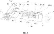
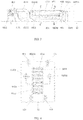
- the present invention provides a rain awning system 8 configured for providing a rain-proof function when a door of a vehicle is opened upwardly
- the rain awning system comprises an awning stretching and receiving device 81 mounted on a frame front crossbeam
- the awning stretching and receiving device 81 comprises a roller 811, an awning fabric rolled around the roller 811, and a drive assembly 813 configured for driving the roller 81 to rotate
- both the roller 811 and the drive assembly 813 are fixed on the frame front crossbeam. Since an area that needs to be shielded from raining is big, a big area of a stretched awning fabric 812 is also needed.
- the awning fabric 812 is arranged in such a way that the awing fabric 812 can be rolled when it does not need to be stretched, and can be stretched to open when it needs to be used. Therefore, the awning stretching and receiving device 81 is configured to comprise the roller 811, the awning fabric 812 and the drive assembly 813 configured for driving the roller 811 to rotate; one end of the awning fabric 812 is fixedly connected to the roller 811, and another end of the awning fabric 812 is a free end which can be freely stretched.
- the drive assembly 81 drives the roller 811 to rotate, such that a function of rolling up or stretching the awning fabric 812 can be implemented, and a compactness of a structure and a grade of the whole vehicle can be promoted.
- the frame front crossbeam is connected with a support plate 82
- the rain awning system 8 further comprises an awning fabric drive device 83 mounted on the support plate 82 and configured to drive the awning fabric 812 rolled around the roller 811 to stretch; a guide assembly 84 configured for guiding a movement of the awning fabric 812 is arranged between the awning fabric 812 and the door of the vehicle.
- Driving the awning fabric 812 to stretch is implemented by the awning fabric drive device 83, the drive assembly 813 arranged on the frame front crossbeam can provide an auxiliary function of releasing the rolled awning fabric 812 when the awning fabric 812 is stretched; rolling the awning fabric 812 is implemented by the drive assembly 813, at this time, the awning fabric drive assembly 83 provides an auxiliary pulling back function. Meanwhile, when the awning fabric 812 is stretched or rolled, the guide assembly 84 arranged between the awning fabric 812 and the door of the vehicle can provide a guide function to ensure that the awning fabric 812 can be stretched or rolled successfully, and make the awning fabric 812 to be stretched or rolled in a predetermined shape so as to ensure an operational reliability.
- the drive assembly 813 driving the roller 811 to rotate, and the awning fabric drive device 83 stretching or rolling the awning fabric 812 can be implemented, so that a driver can be provided with the wind-proof and rain-proof functions, and a driving comfort can be ensured.
- the guide assembly 84 is arranged between the awning fabric 812 and the door of the vehicle and can provide a guiding function when the awning fabric 812 is stretched or rolled, such that the reliability of stretching or rolling the awning fabric 812 can be ensured.
- the awning fabric drive device 83 has a stabilizing function and a quick response of driving the awning fabric 812 to stretch, thereby meeting the using requirement and ensuring the operational reliability of the whole rain awning system 3.
- the awning fabric drive device 83 comprises a power assembly 83 and a receiving assembly 832, both the power assembly 831 and the receiving assembly 832 are connected on the support plate 82.
- the support plate 82 is perpendicularly connected to the frame front crossbeam, and both the power assembly 831 and the receiving assembly 832 arranged on the support board 82 are located at a middle point position of the roller 811, in this way, it is convenient for the power assembly 831 to suffer a uniform force and keep balance when it drives the awning fabric 812to stretch, and a stuck of the awning fabric 812 won't occur.
- the power assembly 831 can be a chain wheel-chain mechanism or a pulley-hauling rope mechanism, and can also be a mechanism that can provide variable hauling paths, such as a blower-air hose mechanism, and so on.
- the receiving assembly 832 is arranged at a rear of the power assembly 831 and configured for receiving the hauling piece having reserved an enough length, such that the requirement for the length of the hauling piece can be met when the awning fabric 812 is pulled to be stretched; meanwhile, a cleanliness of the whole mechanism can also be ensured, which is convenient for the hauling piece to be retracted or released successfully.
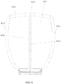
- the power assembly 831 comprises a blower 8311 and an air hose 8312, one end of the air hose 8312 is connected to the blower 8311, and another end of the air hose 8312 is connected with the awning fabric 812, the blower 8311 is connected in series with a gas distributing valve 8313, the awning fabric 812 is provided therein with a plurality of gas-guide pipes and provided thereon with a gas inlet 8314, and another end of the air hose is connected to the gas inlet 8314.
- the awning fabric 812 is made of a double layer water-proof cloth, and the gas-guide pipes 8315 are arranged between the two layers of the water-proof cloth.
- both the air hose 8312 and the gas-guide pipes 8315 are pipes having good flexibility and capable of being plastically bent and curled; in this way, it is convenient for the awning fabric 812 to be rolled around the roller 811 and also convenient for the air hose 8312 to be coiled around the receiving assembly 832.
- the blower 8311 starts to work and transmits high pressure gas through the air hose 8312, the high pressure gas is distributed by the gas distributing valve 8313 and enters the gas-guide pipes 8315 from the gas inlet 8314.
- the blower 8311 stops supplying gas
- the drive assembly 813 and the receiving assembly 832 work together
- the drive assembly 813 drives the roller 811 to rotate reversely so as to roll the awning fabric 812
- the high pressure gas in the gas-guide pipes 8315 is vented out through the gas distributing valve 8313
- the receiving assembly 832 receives redundant air hose 8312, thereby ensuring convenient driving and stretching in the next use.
- both two sides and a head portion of a stretched end of the awning fabric 812 are provided with gas-guide pipes 8315, the gas-guide pipes 8315 communicate with each other, the gas inlet 8314 is disposed at a middle point of one of the gas-guide pipes 8315 that is arranged at the stretched end, the air hose 8312 extends from a tail end of the awning fabric 812 towards the stretched end of the awning fabric 812 along a symmetric line of the awning fabric 812, and is connected to the gas inlet 8314.
- the high pressure gas is input by the air hose 8312 into the awning fabric 812, and is dredged and distributed by the gas-guide pipes, so that the awning fabric 812 rolled around the roller 811 initially can be stretched evenly and quickly, thereby achieving the rain-proof function. Since both the two sides and the head portion of the stretched end of the awning fabric 812 are provided with the gas-guide pipes 8315, by this symmetric arrangement, not only can a balance of generated drive force be ensured, the awning fabric 812 can also be provided with enough driving force, thereby ensuring that the awning fabric 812 can be stretched successfully.
- the receiving assembly 832 comprises an air hose guide fixing base 8321, an air hose guide stretching and retracting base 8322 that can slide on the support plate 82, and an air hose drive assembly fixed on the support plate 82 and configured to drive the air hose stretching and retracting base 8322 to slide; each of the air hose guide fixing base 8321 and the air hose guide stretching and retracting base 8322 is provided thereon with a plurality of air hose guide shafts 8324, and the air hose 8312 is coiled around the air hose guide shafts 8324 circuitously.
- each of the air hose guide fixing base 8321 and the air hose guide stretching and retracting base 8322 is provided with the plurality of rotatable air hose guide shafts 8324 respectively, and the air hose 8312 is coiled around the air hose guide shafts 8324 circuitously.
- the rotatable air hose guide shafts 8324 have smaller friction resistances, therefore, the air hose guide shafts 8324 can provide guide functions in the stretching or retracting process of the air hose 8312, thereby providing convenience for the air hose 8312 to be stretched or retracted.
- the air hose drive assembly can be a chain wheel-chain mechanism, a gear-rack mechanism, or a led screw mechanism, and can also be a pulley-hauling rope mechanism.
- the air hose drive assembly comprises a hauling rope 83231, a guide wheel fixing base 83232 and an air hose drive motor 83233, the guide wheel fixing base 83232 and the air hose drive motor 83233 are arranged oppositely on the support plate 82, and both the air hose guide fixing base 8321 and the air hose guide stretching and retracting base 8322 are arranged between the guide wheel fixing base 83232 and the air hose drive motor 83233; the air hose guide fixing base 8321 is fixedly connected with a mounting plate 83234, and the guide wheel fixing base 83232 is fixedly mounted on the mounting plate 83234; each of the guide wheel fixing base 83232 and the air hose drive motor 83233 is provided with a plurality of hauling rope guide wheels 83
- the air hose guide fixing base 8321 is fixedly mounted on the support plate 82, and the mounting plate 83234 is fixedly connected with the support plate 82; the guide wheel fixing base 83232 is then mounted fixedly on one end of the mounting plate 83234, and the air hose drive motor 83233 is mounted on a position of the support plate 82 that corresponds to another end of the mounting plate 83234; in this way, the air hose guide stretching and retracting base 8322 can move back and forth between the air hose guide fixing base 8321 and the air hose drive motor 83233.
- each of the guide wheel fixing base 83232 and the air hose drive motor 83233 is provided with a plurality of hauling rope guide wheels 83235 configured to provide guide functions for the movement of the hauling rope 83231, thereby facilitating hauling the air hose guide stretching and retracting base 8322 and further ensuring that the awning fabric 812 can be stretched or rolled successfully.
- one end of the hauling rope 83231 is connected to the air hose guide stretching and retracting base 8322 through a spring 83236.
- the air hose drive motor 83233 drives the air hose guide stretching and retracting base 8322 to move through the hauling rope 83231.
- either end of the hauling rope 83231 connected to the air hose guide stretching and retracting base 8322 is provided with the spring 83236.
- the spring 83236 can provide a buffer function, thereby enabling the air hose guide stretching and retracting base 8322 to move smoothly and will not generate any sudden movement.
- each of the mounting plate 83234 and the support plate 82 is provided with a guide rail 834; each of an upper end and a lower end of the air hose guide stretching and retracting base 8322 is provided with a roll wheel, and the roll wheels 835 are correspondingly connected with the guide tracks 834.
- the air hose guide stretching and retracting base 8322 can moved smoothly and conveniently, and a reliability of stretching or rolling the awning fabric 812 is further ensured.
- the drive assembly 813 comprises two roller drive motors 8131 arranged at two ends of the roller 811 respectively and a transmission belt 8132 configured to connect the roller 811 with the roller drive motors 8131, and the roller drive motors 8131 and the roller 811 are arranged in parallel on the frame front crossbeam.
- Two ends of the roller 811 are provided with two roller drive motors 8131 respectively, such that the roller 811 has enough turning force to stretch out or roll up the awning fabric 812, thereby ensuring that the awning fabric 812 can be stretched or rolled successfully, and further ensuring the balance of the turning force.
- roller drive motors 8131 and the roller 811 are arranged in parallel, not only can transmission be performed conveniently, but also the transmission belt 8132 can provide a buffer function when the roller drive motor 8131 rotates suddenly, thereby ensuring a smoothness of movement.
- the roller drive motor 8131 and the roller 811 can also be arranged coaxially, and the roller drive motor 8131 directly drives the roller 811 to move; at this time, there is no need to additionally arrange the transmission belt 8132 for transmission, so that the cost is saved.
- the guide assembly 84 comprises two slide ways 841 arranged oppositely on the door of the vehicle and two awning pull rod 842, each awning pull rod 842 having one end connected to the awning fabric 812 and another end connected to one of the slide ways 841, and the end of each awning fabric 842 connected to the corresponding slide way 841 is provided with a pulley 843.
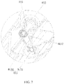
- a cross section of the slide way 841 shows a notched circular shape.
- the pulley 843 By arranging the pulley 843 in the slide way 841, not only can the pulley 843 move freely along the slide way 841 so as to provide a guide function for stretching or rolling of the awning fabric 812, but also the slide way 841 having the notched circular shape can prevent the pulley 843 arranged therein from dropping out, for this reason, there is no need to further limit the position of the pulley 843.
- the awning pull rod 842 can not only provide the transmission guidance function, but also provide a function of keeping a stretched shape of the awning fabric 812 after the awning fabric 812 is stretched.
- the present invention further provides an electric vehicle comprising the aforesaid rain awning system 8.
- the rain awning system 8 can perform the stretching or retracting actions quickly and is reliable in use.
- the electric vehicle that adopts the aforesaid rain awning system 8 can provide a driver with the wind-proof and rain-proof functions when it rains and the door of the vehicle is opened, has a high degree of humanization, and thus it is ensured that the electric vehicle can be used normally when it rains. Meanwhile, by the arrangement of the awning fabric rain-proof system 8, the grade of the whole vehicle can be promoted.
Landscapes
- Engineering & Computer Science (AREA)
- Mechanical Engineering (AREA)
- General Engineering & Computer Science (AREA)
- Tents Or Canopies (AREA)
Claims (9)
- Système d'auvent contre la pluie (8) conçu pour assurer une fonction anti-pluie lorsqu'une portière d'un véhicule est ouverte vers le haut, le système d'auvent contre la pluie (8) comprend : un dispositif d'étirement et de réception d'auvent (81) monté sur une traverse avant d'un cadre, le dispositif d'étirement et de réception d'auvent (81) comprend un rouleau (811), un tissu d'auvent (812) enroulé autour du rouleau (811) et un ensemble d'entraînement (813) conçu pour entraîner le rouleau (811) en rotation ; le rouleau (811) et l'ensemble d'entraînement (813) sont tous deux fixés sur la traverse avant du cadre, et la traverse avant du cadre est connectée à une plaque de support (82) ; le système d'auvent contre la pluie (8) comprend en outre un dispositif d'entraînement de tissu d'auvent (83) disposé sur la plaque de support (82) et conçu pour entraîner le tissu d'auvent (812) enroulé autour du rouleau (811) pour qu'il s'étire vers l'extérieur, et un ensemble de guidage (84) conçu pour guider un mouvement du tissu d'auvent (812) est conçu pour être disposé entre le tissu d'auvent (812) et la portière du véhicule ; le dispositif d'entraînement de tissu d'auvent (812) comprend un ensemble de puissance (831) et un ensemble de réception (832), l'ensemble de puissance (831) et l'ensemble de réception (832) sont tous deux connectés sur la plaque de support (82) ; le système d'auvent contre la pluie est caractérisé en ce que : l'ensemble de puissance (831) comprend une soufflante (8311) et un tuyau d'air (8312), une extrémité du tuyau d'air (8312) est connectée à la soufflante (8311) et l'autre extrémité du tuyau d'air (8312) est connectée au tissu d'auvent (812) ; la soufflante (8311) est connectée en série à une soupape de distribution d'air (8313), le tissu d'auvent (812) est muni, dans celui-ci, d'une pluralité de tubes de guidage de gaz (8315) et muni, sur celui-ci, d'une entrée de gaz (8314), et l'autre extrémité du tuyau d'air (8312) est connectée à l'entrée de gaz (8314).
- Système d'auvent contre la pluie (8) selon la revendication 1, qui est caractérisé en ce que : deux côtés et une partie de tête d'une extrémité étirée du tissu d'auvent (812) sont munis de la pluralité de tubes de guidage de gaz (8315), la pluralité de tubes de guidage de gaz (8315) communiquent les uns avec les autres ; l'entrée de gaz (8314) est disposée au niveau d'un point médian de l'un des tubes de guidage de gaz (8315) disposé au niveau de l'extrémité étirée du tissu d'auvent (812), le tuyau d'air (8312) s'étend depuis une extrémité de queue du tissu d'auvent (812) vers l'extrémité étirée du tissu d'auvent (812) le long d'une ligne de symétrie du tissu d'auvent (812) et est connecté à l'entrée de gaz (8314).
- Système d'auvent contre la pluie (8) selon la revendication 1, qui est caractérisé en ce que : l'ensemble de réception (832) comprend une base de fixation pour guidage du tuyau d'air (8321) montée de manière fixe sur la plaque de support (82), une base d'étirement et de rétraction pour guidage du tuyau d'air (8322) qui peut coulisser sur la plaque de support (82), et un ensemble d'entraînement de tuyau d'air fixe sur la plaque de support (82) et conçu pour entraîner la base d'étirement et de rétraction pour guidage du tuyau d'air (8322) en coulissement ; la base de fixation pour guidage du tuyau d'air (8321) et la base d'étirement et de rétraction pour guidage du tuyau d'air (8322) sont respectivement munies d'une pluralité d'arbres guidant le tuyau d'air (8324) rotatifs, et le tuyau d'air (8312) s'enroule autour des arbres guidant le tuyau d'air (8324) en formant un circuit tortueux.
- Système d'auvent contre la pluie (8) selon la revendication 1, qui est caractérisé en ce que : l'ensemble d'entraînement de tuyau d'air comprend un câble de traction (83231), une base de fixation pour roues de guidage (83232), et un moteur d'entraînement pour tuyau d'air (83233), la base de fixation pour roues de guidage (83232) et le moteur d'entraînement pour tuyau d'air (83233) sont disposés en vis-à-vis sur la plaque de support (82), et la base de fixation pour guidage du tuyau d'air (8321) et la base d'étirement et de rétraction pour guidage du tuyau d'air (8322) sont toutes deux disposées entre la base de fixation pour roues de guidage (83232) et le moteur d'entraînement pour tuyau d'air (83233) ; la base de fixation pour guidage du tuyau d'air (83233) est connectée de manière fixe à une plaque de montage (83234), et la base de fixation pour guidage du tuyau d'air (83232) est montée de manière fixe sur la plaque de montage (83234), chacun de la base de fixation pour roues de guidage (83232) et du moteur d'entraînement pour tuyau d'air (83233) est muni d'une pluralité de roues de guidage pour câble de traction (83235), le câble de traction (83231) passe sur les roues de guidage pour câble de traction (83235), et les deux extrémités du câble de traction (83231) sont toutes deux connectées à la base d'étirement et de rétraction pour guidage du tuyau d'air (8322).
- Système d'auvent contre la pluie (8) selon la revendication 4, qui est caractérisé en ce que : une extrémité du câble de traction (83231) est connectée à la base d'étirement et de rétraction pour guidage du tuyau d'air (8322) par l'intermédiaire d'un ressort (83236).
- Système d'auvent contre la pluie (8) selon la revendication 4, qui est caractérisé en ce que : chacune de la plaque de montage (83234) et de la plaque de support (82) est munie d'un rail de guidage (834), chacune d'une extrémité supérieure et d'une extrémité inférieure de la base d'étirement et de rétraction pour guidage du tuyau d'air (8322) est munie d'un galet (835), et chaque galet (835) est disposé en correspondance sur le rail de guidage (834).
- Système d'auvent contre la pluie (8) selon l'une quelconque des revendications 1 à 6, qui est caractérisé en ce que : l'ensemble d'entraînement comprend deux moteurs d'entraînement pour rouleau (8131) respectivement disposés sur deux extrémités du rouleau (811) et une courroie de transmission (8132) conçue pour relier le rouleau (811) aux moteurs d'entraînement pour rouleau (8131), les moteurs d'entraînement pour rouleau (8131) et le rouleau (811) sont disposés en parallèle sur la traverse avant du cadre.
- Système d'auvent contre la pluie (8) selon l'une quelconque des revendications 1 à 6, qui est caractérisé en ce que : l'ensemble de guidage (84) comprend deux glissières (841) disposées en vis-à-vis sur la portière du véhicule, et deux bielles de tirage d'auvent (842), chaque bielle de tirage d'auvent (842) a une extrémité connectée au tissu d'auvent (812) et une autre extrémité connectée à l'une des glissières (841), et l'extrémité de la bielle de tirage d'auvent (842) connectée à la glissière (841) correspondante est munie d'une poulie (843).
- Véhicule électrique, caractérisé en ce que le véhicule électrique comprend le système d'auvent contre la pluie (8) selon l'une quelconque des revendications 1 à 8.
Priority Applications (1)
| Application Number | Priority Date | Filing Date | Title |
|---|---|---|---|
| PL14887870T PL3127732T3 (pl) | 2014-04-01 | 2014-04-01 | System markizy przeciwdeszczowej i pojazd elektryczny mający taki system |
Applications Claiming Priority (1)
| Application Number | Priority Date | Filing Date | Title |
|---|---|---|---|
| PCT/CN2014/074538 WO2015149278A1 (fr) | 2014-04-01 | 2014-04-01 | Système d'auvent contre la pluie et véhicule électrique en étant doté |
Publications (3)
| Publication Number | Publication Date |
|---|---|
| EP3127732A1 EP3127732A1 (fr) | 2017-02-08 |
| EP3127732A4 EP3127732A4 (fr) | 2018-01-03 |
| EP3127732B1 true EP3127732B1 (fr) | 2019-03-13 |
Family
ID=54239265
Family Applications (1)
| Application Number | Title | Priority Date | Filing Date |
|---|---|---|---|
| EP14887870.5A Active EP3127732B1 (fr) | 2014-04-01 | 2014-04-01 | Système d'auvent contre la pluie et véhicule électrique en étant doté |
Country Status (8)
| Country | Link |
|---|---|
| US (1) | US9956856B2 (fr) |
| EP (1) | EP3127732B1 (fr) |
| JP (1) | JP6353071B2 (fr) |
| KR (1) | KR102182843B1 (fr) |
| CN (1) | CN106457988B (fr) |
| ES (1) | ES2730299T3 (fr) |
| PL (1) | PL3127732T3 (fr) |
| WO (1) | WO2015149278A1 (fr) |
Families Citing this family (1)
| Publication number | Priority date | Publication date | Assignee | Title |
|---|---|---|---|---|
| KR20200069856A (ko) | 2018-12-07 | 2020-06-17 | 배성원 | 바나나향이 첨가된 고구마 제조방법 |
Family Cites Families (17)
| Publication number | Priority date | Publication date | Assignee | Title |
|---|---|---|---|---|
| JPS58194626A (ja) | 1982-05-09 | 1983-11-12 | Masatsugu Tanaka | 降雨時の出入りを容易とした車両の雨避け庇装置 |
| JPS60103017U (ja) * | 1983-08-18 | 1985-07-13 | 三菱自動車工業株式会社 | 自動車用雨よけ装置 |
| DE3909937C2 (de) * | 1989-03-25 | 1994-05-11 | Man Nutzfahrzeuge Gmbh | Elektrisch verfahrbare Markise für ein Personenbeförderungsfahrzeug, insbesondere Omnibus |
| JPH0731447U (ja) * | 1993-11-24 | 1995-06-13 | 勇一 後藤 | 自動車用雨除け装置 |
| CN2260030Y (zh) | 1996-04-17 | 1997-08-20 | 刘文景 | 汽车车体与车门之间的遮雨结构 |
| JP2002225567A (ja) * | 2001-02-01 | 2002-08-14 | Shigero Makishima | 自動車ドアの雨覆い装置 |
| US20030192581A1 (en) | 2002-04-11 | 2003-10-16 | Chang En Koung | Shielding device for vehicle while opening the door |
| JP2004001622A (ja) * | 2002-05-31 | 2004-01-08 | Chuo Spring Co Ltd | 車両用雨除け装置 |
| CN2586602Y (zh) * | 2002-11-15 | 2003-11-19 | 田镇平 | 展收式汽车遮雨篷 |
| DE10316592A1 (de) * | 2003-04-11 | 2004-10-28 | Daimlerchrysler Ag | Ausfahrbare Schutzmarkise und Kraftfahrzeug mit Schutzmarkise |
| DE602005010687D1 (de) * | 2005-07-18 | 2008-12-11 | Gm Global Tech Operations Inc | Türöffnungs- und -schliesssystem für Fahrzeuge |
| JP2007176213A (ja) * | 2005-12-27 | 2007-07-12 | Asmo Co Ltd | 車両用雨除け装置 |
| CN101239613A (zh) | 2008-03-10 | 2008-08-13 | 江门市景贤学校 | 一种带车门挡雨蓬的汽车 |
| JP2009262906A (ja) * | 2008-04-24 | 2009-11-12 | Keiji Okamoto | 自動車用防雨防紫外線装置 |
| US7604281B1 (en) * | 2008-09-26 | 2009-10-20 | Raynor Eileen M | Rain guard |
| KR101347246B1 (ko) * | 2012-11-22 | 2014-01-06 | 동아대학교 산학협력단 | 자동차 빗물 차단 장치 |
| CN103600640A (zh) | 2013-11-28 | 2014-02-26 | 陈科 | 设置在公交车上的自动伸缩雨篷 |
-
2014
- 2014-04-01 PL PL14887870T patent/PL3127732T3/pl unknown
- 2014-04-01 ES ES14887870T patent/ES2730299T3/es active Active
- 2014-04-01 JP JP2016560755A patent/JP6353071B2/ja not_active Expired - Fee Related
- 2014-04-01 US US15/300,523 patent/US9956856B2/en active Active
- 2014-04-01 CN CN201480077548.4A patent/CN106457988B/zh not_active Expired - Fee Related
- 2014-04-01 EP EP14887870.5A patent/EP3127732B1/fr active Active
- 2014-04-01 WO PCT/CN2014/074538 patent/WO2015149278A1/fr not_active Ceased
- 2014-04-01 KR KR1020167028869A patent/KR102182843B1/ko not_active Expired - Fee Related
Non-Patent Citations (1)
| Title |
|---|
| None * |
Also Published As
| Publication number | Publication date |
|---|---|
| CN106457988B (zh) | 2019-03-12 |
| JP2017509543A (ja) | 2017-04-06 |
| JP6353071B2 (ja) | 2018-07-04 |
| KR102182843B1 (ko) | 2020-11-26 |
| PL3127732T3 (pl) | 2019-09-30 |
| ES2730299T3 (es) | 2019-11-11 |
| US20170120733A1 (en) | 2017-05-04 |
| CN106457988A (zh) | 2017-02-22 |
| EP3127732A4 (fr) | 2018-01-03 |
| EP3127732A1 (fr) | 2017-02-08 |
| KR20160138135A (ko) | 2016-12-02 |
| US9956856B2 (en) | 2018-05-01 |
| WO2015149278A1 (fr) | 2015-10-08 |
Similar Documents
| Publication | Publication Date | Title |
|---|---|---|
| CN204263913U (zh) | 一种自动平移式汽车遮阳装置 | |
| CN101439692A (zh) | 用于汽车的遮盖系统 | |
| CN206086320U (zh) | 一种可折叠的车用太阳能板遮阳挡帘 | |
| US9956856B2 (en) | Rain awning system and electric vehicle having same | |
| CN203543614U (zh) | 汽车自动保护伞翼 | |
| CN107985029A (zh) | 一种使汽车减晒降温的新的方法 | |
| CN103072522A (zh) | 钢丝绳隐藏式自动软蓬覆盖系统 | |
| CN207277968U (zh) | 一种汽车遮阳棚 | |
| CN101439656A (zh) | 随拉随停的遮阳装置 | |
| CN209268183U (zh) | 一种温室卷幕系统 | |
| CN105658457A (zh) | 汽车用自动多功能保护蓬装置 | |
| CN212579571U (zh) | 一种车顶罩装置 | |
| CN204956256U (zh) | 一种单层折叠房车 | |
| CN201809913U (zh) | 一种户内外天篷帘 | |
| CN202718431U (zh) | 自动伸缩车库 | |
| CN110203126B (zh) | 一种货物运输车用遮盖货物装置 | |
| CN108819680B (zh) | 一种汽车遮阳装置 | |
| CN103419609A (zh) | 车用防尘罩 | |
| CN105774484A (zh) | 一种太阳能供电的车窗卷帘驱动机构及其使用方法 | |
| CN105172663A (zh) | 一种单层折叠房车 | |
| CN204340618U (zh) | 分段式全景天窗遮阳帘 | |
| CN224048541U (zh) | 一种屋顶分布式光伏组件安全施工装置 | |
| CN222713280U (zh) | 一种汽车天窗电动卷轴遮阳帘 | |
| CN223355369U (zh) | 一种汽车顶棚自动卷帘装置 | |
| RU76289U1 (ru) | Солнцезащитное оборудование кабины машиниста рельсового транспорта |
Legal Events
| Date | Code | Title | Description |
|---|---|---|---|
| STAA | Information on the status of an ep patent application or granted ep patent |
Free format text: STATUS: THE INTERNATIONAL PUBLICATION HAS BEEN MADE |
|
| PUAI | Public reference made under article 153(3) epc to a published international application that has entered the european phase |
Free format text: ORIGINAL CODE: 0009012 |
|
| STAA | Information on the status of an ep patent application or granted ep patent |
Free format text: STATUS: REQUEST FOR EXAMINATION WAS MADE |
|
| 17P | Request for examination filed |
Effective date: 20161028 |
|
| AK | Designated contracting states |
Kind code of ref document: A1 Designated state(s): AL AT BE BG CH CY CZ DE DK EE ES FI FR GB GR HR HU IE IS IT LI LT LU LV MC MK MT NL NO PL PT RO RS SE SI SK SM TR |
|
| AX | Request for extension of the european patent |
Extension state: BA ME |
|
| DAX | Request for extension of the european patent (deleted) | ||
| A4 | Supplementary search report drawn up and despatched |
Effective date: 20171206 |
|
| RIC1 | Information provided on ipc code assigned before grant |
Ipc: B60J 5/04 20060101ALI20171130BHEP Ipc: B60J 9/00 20060101AFI20171130BHEP |
|
| GRAP | Despatch of communication of intention to grant a patent |
Free format text: ORIGINAL CODE: EPIDOSNIGR1 |
|
| STAA | Information on the status of an ep patent application or granted ep patent |
Free format text: STATUS: GRANT OF PATENT IS INTENDED |
|
| INTG | Intention to grant announced |
Effective date: 20180920 |
|
| GRAS | Grant fee paid |
Free format text: ORIGINAL CODE: EPIDOSNIGR3 |
|
| GRAA | (expected) grant |
Free format text: ORIGINAL CODE: 0009210 |
|
| STAA | Information on the status of an ep patent application or granted ep patent |
Free format text: STATUS: THE PATENT HAS BEEN GRANTED |
|
| AK | Designated contracting states |
Kind code of ref document: B1 Designated state(s): AL AT BE BG CH CY CZ DE DK EE ES FI FR GB GR HR HU IE IS IT LI LT LU LV MC MK MT NL NO PL PT RO RS SE SI SK SM TR |
|
| REG | Reference to a national code |
Ref country code: GB Ref legal event code: FG4D |
|
| REG | Reference to a national code |
Ref country code: CH Ref legal event code: EP Ref country code: AT Ref legal event code: REF Ref document number: 1107216 Country of ref document: AT Kind code of ref document: T Effective date: 20190315 |
|
| REG | Reference to a national code |
Ref country code: IE Ref legal event code: FG4D |
|
| REG | Reference to a national code |
Ref country code: DE Ref legal event code: R096 Ref document number: 602014043073 Country of ref document: DE |
|
| RAP2 | Party data changed (patent owner data changed or rights of a patent transferred) |
Owner name: GUANGDONG HUA'CHAN RESEARCH INSTITUTE OF INTELLIGE |
|
| REG | Reference to a national code |
Ref country code: CH Ref legal event code: NV Representative=s name: DENNEMEYER AG, CH |
|
| REG | Reference to a national code |
Ref country code: DE Ref legal event code: R081 Ref document number: 602014043073 Country of ref document: DE Owner name: GUANGDONG HUA'CHAN RESEARCH INSTITUTE OF INTEL, CN Free format text: FORMER OWNER: SHENZHEN ZHILUN DRIVING TECHNOLOGY FOR ELECTRIC VEHICLE CO., LTD., SHENZHEN, GUANGDONG, CN |
|
| REG | Reference to a national code |
Ref country code: NL Ref legal event code: FP Ref country code: NL Ref legal event code: PD Owner name: GUANGDONG HUA'CHAN RESEARCH INSTITUTE OF INTELLIGE Free format text: DETAILS ASSIGNMENT: CHANGE OF OWNER(S), ASSIGNMENT; FORMER OWNER NAME: SHENZHEN ZHILUN DRIVING TECHNOLOGY FOR ELECTRIC VEHICLE CO. LTD. Effective date: 20190613 |
|
| REG | Reference to a national code |
Ref country code: LT Ref legal event code: MG4D |
|
| PG25 | Lapsed in a contracting state [announced via postgrant information from national office to epo] |
Ref country code: LT Free format text: LAPSE BECAUSE OF FAILURE TO SUBMIT A TRANSLATION OF THE DESCRIPTION OR TO PAY THE FEE WITHIN THE PRESCRIBED TIME-LIMIT Effective date: 20190313 Ref country code: FI Free format text: LAPSE BECAUSE OF FAILURE TO SUBMIT A TRANSLATION OF THE DESCRIPTION OR TO PAY THE FEE WITHIN THE PRESCRIBED TIME-LIMIT Effective date: 20190313 Ref country code: NO Free format text: LAPSE BECAUSE OF FAILURE TO SUBMIT A TRANSLATION OF THE DESCRIPTION OR TO PAY THE FEE WITHIN THE PRESCRIBED TIME-LIMIT Effective date: 20190613 Ref country code: SE Free format text: LAPSE BECAUSE OF FAILURE TO SUBMIT A TRANSLATION OF THE DESCRIPTION OR TO PAY THE FEE WITHIN THE PRESCRIBED TIME-LIMIT Effective date: 20190313 |
|
| REG | Reference to a national code |
Ref country code: GB Ref legal event code: 732E Free format text: REGISTERED BETWEEN 20190718 AND 20190724 |
|
| REG | Reference to a national code |
Ref country code: BE Ref legal event code: PD Owner name: GUANGDONG HUA'CHAN RESEARCH INSTITUTE OF INTELLIG Free format text: DETAILS ASSIGNMENT: CHANGE OF OWNER(S), CESSION; FORMER OWNER NAME: SHENZHEN ZHILUN DRIVING TECHNOLOGY FOR ELECTRIC VEHICLE CO. LTD. Effective date: 20190611 |
|
| PG25 | Lapsed in a contracting state [announced via postgrant information from national office to epo] |
Ref country code: RS Free format text: LAPSE BECAUSE OF FAILURE TO SUBMIT A TRANSLATION OF THE DESCRIPTION OR TO PAY THE FEE WITHIN THE PRESCRIBED TIME-LIMIT Effective date: 20190313 Ref country code: GR Free format text: LAPSE BECAUSE OF FAILURE TO SUBMIT A TRANSLATION OF THE DESCRIPTION OR TO PAY THE FEE WITHIN THE PRESCRIBED TIME-LIMIT Effective date: 20190614 Ref country code: HR Free format text: LAPSE BECAUSE OF FAILURE TO SUBMIT A TRANSLATION OF THE DESCRIPTION OR TO PAY THE FEE WITHIN THE PRESCRIBED TIME-LIMIT Effective date: 20190313 Ref country code: BG Free format text: LAPSE BECAUSE OF FAILURE TO SUBMIT A TRANSLATION OF THE DESCRIPTION OR TO PAY THE FEE WITHIN THE PRESCRIBED TIME-LIMIT Effective date: 20190613 Ref country code: LV Free format text: LAPSE BECAUSE OF FAILURE TO SUBMIT A TRANSLATION OF THE DESCRIPTION OR TO PAY THE FEE WITHIN THE PRESCRIBED TIME-LIMIT Effective date: 20190313 |
|
| PG25 | Lapsed in a contracting state [announced via postgrant information from national office to epo] |
Ref country code: PT Free format text: LAPSE BECAUSE OF FAILURE TO SUBMIT A TRANSLATION OF THE DESCRIPTION OR TO PAY THE FEE WITHIN THE PRESCRIBED TIME-LIMIT Effective date: 20190713 Ref country code: CZ Free format text: LAPSE BECAUSE OF FAILURE TO SUBMIT A TRANSLATION OF THE DESCRIPTION OR TO PAY THE FEE WITHIN THE PRESCRIBED TIME-LIMIT Effective date: 20190313 Ref country code: AL Free format text: LAPSE BECAUSE OF FAILURE TO SUBMIT A TRANSLATION OF THE DESCRIPTION OR TO PAY THE FEE WITHIN THE PRESCRIBED TIME-LIMIT Effective date: 20190313 Ref country code: EE Free format text: LAPSE BECAUSE OF FAILURE TO SUBMIT A TRANSLATION OF THE DESCRIPTION OR TO PAY THE FEE WITHIN THE PRESCRIBED TIME-LIMIT Effective date: 20190313 Ref country code: IT Free format text: LAPSE BECAUSE OF FAILURE TO SUBMIT A TRANSLATION OF THE DESCRIPTION OR TO PAY THE FEE WITHIN THE PRESCRIBED TIME-LIMIT Effective date: 20190313 Ref country code: SK Free format text: LAPSE BECAUSE OF FAILURE TO SUBMIT A TRANSLATION OF THE DESCRIPTION OR TO PAY THE FEE WITHIN THE PRESCRIBED TIME-LIMIT Effective date: 20190313 Ref country code: RO Free format text: LAPSE BECAUSE OF FAILURE TO SUBMIT A TRANSLATION OF THE DESCRIPTION OR TO PAY THE FEE WITHIN THE PRESCRIBED TIME-LIMIT Effective date: 20190313 |
|
| REG | Reference to a national code |
Ref country code: ES Ref legal event code: FG2A Ref document number: 2730299 Country of ref document: ES Kind code of ref document: T3 Effective date: 20191111 |
|
| PG25 | Lapsed in a contracting state [announced via postgrant information from national office to epo] |
Ref country code: SM Free format text: LAPSE BECAUSE OF FAILURE TO SUBMIT A TRANSLATION OF THE DESCRIPTION OR TO PAY THE FEE WITHIN THE PRESCRIBED TIME-LIMIT Effective date: 20190313 |
|
| REG | Reference to a national code |
Ref country code: DE Ref legal event code: R097 Ref document number: 602014043073 Country of ref document: DE |
|
| PG25 | Lapsed in a contracting state [announced via postgrant information from national office to epo] |
Ref country code: IS Free format text: LAPSE BECAUSE OF FAILURE TO SUBMIT A TRANSLATION OF THE DESCRIPTION OR TO PAY THE FEE WITHIN THE PRESCRIBED TIME-LIMIT Effective date: 20190713 Ref country code: LU Free format text: LAPSE BECAUSE OF NON-PAYMENT OF DUE FEES Effective date: 20190401 |
|
| PLBE | No opposition filed within time limit |
Free format text: ORIGINAL CODE: 0009261 |
|
| STAA | Information on the status of an ep patent application or granted ep patent |
Free format text: STATUS: NO OPPOSITION FILED WITHIN TIME LIMIT |
|
| PG25 | Lapsed in a contracting state [announced via postgrant information from national office to epo] |
Ref country code: DK Free format text: LAPSE BECAUSE OF FAILURE TO SUBMIT A TRANSLATION OF THE DESCRIPTION OR TO PAY THE FEE WITHIN THE PRESCRIBED TIME-LIMIT Effective date: 20190313 Ref country code: MC Free format text: LAPSE BECAUSE OF FAILURE TO SUBMIT A TRANSLATION OF THE DESCRIPTION OR TO PAY THE FEE WITHIN THE PRESCRIBED TIME-LIMIT Effective date: 20190313 |
|
| 26N | No opposition filed |
Effective date: 20191216 |
|
| PG25 | Lapsed in a contracting state [announced via postgrant information from national office to epo] |
Ref country code: SI Free format text: LAPSE BECAUSE OF FAILURE TO SUBMIT A TRANSLATION OF THE DESCRIPTION OR TO PAY THE FEE WITHIN THE PRESCRIBED TIME-LIMIT Effective date: 20190313 |
|
| PG25 | Lapsed in a contracting state [announced via postgrant information from national office to epo] |
Ref country code: IE Free format text: LAPSE BECAUSE OF NON-PAYMENT OF DUE FEES Effective date: 20190401 |
|
| PG25 | Lapsed in a contracting state [announced via postgrant information from national office to epo] |
Ref country code: CY Free format text: LAPSE BECAUSE OF FAILURE TO SUBMIT A TRANSLATION OF THE DESCRIPTION OR TO PAY THE FEE WITHIN THE PRESCRIBED TIME-LIMIT Effective date: 20190313 |
|
| PGFP | Annual fee paid to national office [announced via postgrant information from national office to epo] |
Ref country code: TR Payment date: 20210330 Year of fee payment: 8 |
|
| PG25 | Lapsed in a contracting state [announced via postgrant information from national office to epo] |
Ref country code: MT Free format text: LAPSE BECAUSE OF FAILURE TO SUBMIT A TRANSLATION OF THE DESCRIPTION OR TO PAY THE FEE WITHIN THE PRESCRIBED TIME-LIMIT Effective date: 20190313 Ref country code: HU Free format text: LAPSE BECAUSE OF FAILURE TO SUBMIT A TRANSLATION OF THE DESCRIPTION OR TO PAY THE FEE WITHIN THE PRESCRIBED TIME-LIMIT; INVALID AB INITIO Effective date: 20140401 |
|
| PGFP | Annual fee paid to national office [announced via postgrant information from national office to epo] |
Ref country code: DE Payment date: 20210420 Year of fee payment: 8 Ref country code: FR Payment date: 20210423 Year of fee payment: 8 |
|
| PGFP | Annual fee paid to national office [announced via postgrant information from national office to epo] |
Ref country code: CH Payment date: 20210420 Year of fee payment: 8 Ref country code: ES Payment date: 20210621 Year of fee payment: 8 Ref country code: PL Payment date: 20210331 Year of fee payment: 8 Ref country code: AT Payment date: 20210421 Year of fee payment: 8 Ref country code: BE Payment date: 20210420 Year of fee payment: 8 Ref country code: GB Payment date: 20210422 Year of fee payment: 8 |
|
| PGFP | Annual fee paid to national office [announced via postgrant information from national office to epo] |
Ref country code: NL Payment date: 20210420 Year of fee payment: 8 |
|
| PG25 | Lapsed in a contracting state [announced via postgrant information from national office to epo] |
Ref country code: MK Free format text: LAPSE BECAUSE OF FAILURE TO SUBMIT A TRANSLATION OF THE DESCRIPTION OR TO PAY THE FEE WITHIN THE PRESCRIBED TIME-LIMIT Effective date: 20190313 |
|
| REG | Reference to a national code |
Ref country code: DE Ref legal event code: R119 Ref document number: 602014043073 Country of ref document: DE |
|
| REG | Reference to a national code |
Ref country code: AT Ref legal event code: UEP Ref document number: 1107216 Country of ref document: AT Kind code of ref document: T Effective date: 20190313 |
|
| REG | Reference to a national code |
Ref country code: CH Ref legal event code: PL |
|
| REG | Reference to a national code |
Ref country code: NL Ref legal event code: MM Effective date: 20220501 |
|
| REG | Reference to a national code |
Ref country code: AT Ref legal event code: MM01 Ref document number: 1107216 Country of ref document: AT Kind code of ref document: T Effective date: 20220401 |
|
| GBPC | Gb: european patent ceased through non-payment of renewal fee |
Effective date: 20220401 |
|
| REG | Reference to a national code |
Ref country code: BE Ref legal event code: MM Effective date: 20220430 |
|
| PG25 | Lapsed in a contracting state [announced via postgrant information from national office to epo] |
Ref country code: NL Free format text: LAPSE BECAUSE OF NON-PAYMENT OF DUE FEES Effective date: 20220501 Ref country code: LI Free format text: LAPSE BECAUSE OF NON-PAYMENT OF DUE FEES Effective date: 20220430 Ref country code: GB Free format text: LAPSE BECAUSE OF NON-PAYMENT OF DUE FEES Effective date: 20220401 Ref country code: FR Free format text: LAPSE BECAUSE OF NON-PAYMENT OF DUE FEES Effective date: 20220430 Ref country code: DE Free format text: LAPSE BECAUSE OF NON-PAYMENT OF DUE FEES Effective date: 20221103 Ref country code: CH Free format text: LAPSE BECAUSE OF NON-PAYMENT OF DUE FEES Effective date: 20220430 Ref country code: AT Free format text: LAPSE BECAUSE OF NON-PAYMENT OF DUE FEES Effective date: 20220401 |
|
| PG25 | Lapsed in a contracting state [announced via postgrant information from national office to epo] |
Ref country code: BE Free format text: LAPSE BECAUSE OF NON-PAYMENT OF DUE FEES Effective date: 20220430 |
|
| REG | Reference to a national code |
Ref country code: ES Ref legal event code: FD2A Effective date: 20230605 |
|
| PG25 | Lapsed in a contracting state [announced via postgrant information from national office to epo] |
Ref country code: ES Free format text: LAPSE BECAUSE OF NON-PAYMENT OF DUE FEES Effective date: 20220402 |
|
| PG25 | Lapsed in a contracting state [announced via postgrant information from national office to epo] |
Ref country code: PL Free format text: LAPSE BECAUSE OF NON-PAYMENT OF DUE FEES Effective date: 20220401 |