EP3127740A1 - Parallele modulare wandlerarchitektur zur effizienten erdung von elektrofahrzeugen - Google Patents
Parallele modulare wandlerarchitektur zur effizienten erdung von elektrofahrzeugen Download PDFInfo
- Publication number
- EP3127740A1 EP3127740A1 EP16177458.3A EP16177458A EP3127740A1 EP 3127740 A1 EP3127740 A1 EP 3127740A1 EP 16177458 A EP16177458 A EP 16177458A EP 3127740 A1 EP3127740 A1 EP 3127740A1
- Authority
- EP
- European Patent Office
- Prior art keywords
- power
- ppcs
- vehicle
- motors
- ppc
- Prior art date
- Legal status (The legal status is an assumption and is not a legal conclusion. Google has not performed a legal analysis and makes no representation as to the accuracy of the status listed.)
- Granted
Links
Images


Classifications
-
- H—ELECTRICITY
- H02—GENERATION; CONVERSION OR DISTRIBUTION OF ELECTRIC POWER
- H02M—APPARATUS FOR CONVERSION BETWEEN AC AND AC, BETWEEN AC AND DC, OR BETWEEN DC AND DC, AND FOR USE WITH MAINS OR SIMILAR POWER SUPPLY SYSTEMS; CONVERSION OF DC OR AC INPUT POWER INTO SURGE OUTPUT POWER; CONTROL OR REGULATION THEREOF
- H02M7/00—Conversion of AC power input into DC power output; Conversion of DC power input into AC power output
- H02M7/42—Conversion of DC power input into AC power output without possibility of reversal
- H02M7/44—Conversion of DC power input into AC power output without possibility of reversal by static converters
- H02M7/48—Conversion of DC power input into AC power output without possibility of reversal by static converters using discharge tubes with control electrode or semiconductor devices with control electrode
- H02M7/493—Conversion of DC power input into AC power output without possibility of reversal by static converters using discharge tubes with control electrode or semiconductor devices with control electrode the static converters being arranged for operation in parallel
-
- H—ELECTRICITY
- H02—GENERATION; CONVERSION OR DISTRIBUTION OF ELECTRIC POWER
- H02P—CONTROL OR REGULATION OF ELECTRIC MOTORS, ELECTRIC GENERATORS OR DYNAMO-ELECTRIC CONVERTERS; CONTROLLING TRANSFORMERS, REACTORS OR CHOKE COILS
- H02P27/00—Arrangements or methods for the control of AC motors characterised by the kind of supply voltage
- H02P27/04—Arrangements or methods for the control of AC motors characterised by the kind of supply voltage using variable-frequency supply voltage, e.g. inverter or converter supply voltage
- H02P27/06—Arrangements or methods for the control of AC motors characterised by the kind of supply voltage using variable-frequency supply voltage, e.g. inverter or converter supply voltage using DC to AC converters or inverters
-
- B—PERFORMING OPERATIONS; TRANSPORTING
- B60—VEHICLES IN GENERAL
- B60K—ARRANGEMENT OR MOUNTING OF PROPULSION UNITS OR OF TRANSMISSIONS IN VEHICLES; ARRANGEMENT OR MOUNTING OF PLURAL DIVERSE PRIME-MOVERS IN VEHICLES; AUXILIARY DRIVES FOR VEHICLES; INSTRUMENTATION OR DASHBOARDS FOR VEHICLES; ARRANGEMENTS IN CONNECTION WITH COOLING, AIR INTAKE, GAS EXHAUST OR FUEL SUPPLY OF PROPULSION UNITS IN VEHICLES
- B60K1/00—Arrangement or mounting of electrical propulsion units
- B60K1/02—Arrangement or mounting of electrical propulsion units comprising more than one electric motor
-
- B—PERFORMING OPERATIONS; TRANSPORTING
- B60—VEHICLES IN GENERAL
- B60L—PROPULSION OF ELECTRICALLY-PROPELLED VEHICLES; SUPPLYING ELECTRIC POWER FOR AUXILIARY EQUIPMENT OF ELECTRICALLY-PROPELLED VEHICLES; ELECTRODYNAMIC BRAKE SYSTEMS FOR VEHICLES IN GENERAL; MAGNETIC SUSPENSION OR LEVITATION FOR VEHICLES; MONITORING OPERATING VARIABLES OF ELECTRICALLY-PROPELLED VEHICLES; ELECTRIC SAFETY DEVICES FOR ELECTRICALLY-PROPELLED VEHICLES
- B60L15/00—Methods, circuits, or devices for controlling the traction-motor speed of electrically-propelled vehicles
- B60L15/007—Physical arrangements or structures of drive train converters specially adapted for the propulsion motors of electric vehicles
-
- B—PERFORMING OPERATIONS; TRANSPORTING
- B60—VEHICLES IN GENERAL
- B60L—PROPULSION OF ELECTRICALLY-PROPELLED VEHICLES; SUPPLYING ELECTRIC POWER FOR AUXILIARY EQUIPMENT OF ELECTRICALLY-PROPELLED VEHICLES; ELECTRODYNAMIC BRAKE SYSTEMS FOR VEHICLES IN GENERAL; MAGNETIC SUSPENSION OR LEVITATION FOR VEHICLES; MONITORING OPERATING VARIABLES OF ELECTRICALLY-PROPELLED VEHICLES; ELECTRIC SAFETY DEVICES FOR ELECTRICALLY-PROPELLED VEHICLES
- B60L15/00—Methods, circuits, or devices for controlling the traction-motor speed of electrically-propelled vehicles
- B60L15/20—Methods, circuits, or devices for controlling the traction-motor speed of electrically-propelled vehicles for control of the vehicle or its driving motor to achieve a desired performance, e.g. speed, torque, programmed variation of speed
- B60L15/2009—Methods, circuits, or devices for controlling the traction-motor speed of electrically-propelled vehicles for control of the vehicle or its driving motor to achieve a desired performance, e.g. speed, torque, programmed variation of speed for braking
-
- B—PERFORMING OPERATIONS; TRANSPORTING
- B60—VEHICLES IN GENERAL
- B60L—PROPULSION OF ELECTRICALLY-PROPELLED VEHICLES; SUPPLYING ELECTRIC POWER FOR AUXILIARY EQUIPMENT OF ELECTRICALLY-PROPELLED VEHICLES; ELECTRODYNAMIC BRAKE SYSTEMS FOR VEHICLES IN GENERAL; MAGNETIC SUSPENSION OR LEVITATION FOR VEHICLES; MONITORING OPERATING VARIABLES OF ELECTRICALLY-PROPELLED VEHICLES; ELECTRIC SAFETY DEVICES FOR ELECTRICALLY-PROPELLED VEHICLES
- B60L15/00—Methods, circuits, or devices for controlling the traction-motor speed of electrically-propelled vehicles
- B60L15/32—Control or regulation of multiple-unit electrically-propelled vehicles
- B60L15/38—Control or regulation of multiple-unit electrically-propelled vehicles with automatic control
-
- B—PERFORMING OPERATIONS; TRANSPORTING
- B60—VEHICLES IN GENERAL
- B60L—PROPULSION OF ELECTRICALLY-PROPELLED VEHICLES; SUPPLYING ELECTRIC POWER FOR AUXILIARY EQUIPMENT OF ELECTRICALLY-PROPELLED VEHICLES; ELECTRODYNAMIC BRAKE SYSTEMS FOR VEHICLES IN GENERAL; MAGNETIC SUSPENSION OR LEVITATION FOR VEHICLES; MONITORING OPERATING VARIABLES OF ELECTRICALLY-PROPELLED VEHICLES; ELECTRIC SAFETY DEVICES FOR ELECTRICALLY-PROPELLED VEHICLES
- B60L3/00—Electric devices on electrically-propelled vehicles for safety purposes; Monitoring operating variables, e.g. speed, deceleration or energy consumption
- B60L3/0023—Detecting, eliminating, remedying or compensating for drive train abnormalities, e.g. failures within the drive train
- B60L3/0076—Detecting, eliminating, remedying or compensating for drive train abnormalities, e.g. failures within the drive train relating to braking
-
- B—PERFORMING OPERATIONS; TRANSPORTING
- B60—VEHICLES IN GENERAL
- B60L—PROPULSION OF ELECTRICALLY-PROPELLED VEHICLES; SUPPLYING ELECTRIC POWER FOR AUXILIARY EQUIPMENT OF ELECTRICALLY-PROPELLED VEHICLES; ELECTRODYNAMIC BRAKE SYSTEMS FOR VEHICLES IN GENERAL; MAGNETIC SUSPENSION OR LEVITATION FOR VEHICLES; MONITORING OPERATING VARIABLES OF ELECTRICALLY-PROPELLED VEHICLES; ELECTRIC SAFETY DEVICES FOR ELECTRICALLY-PROPELLED VEHICLES
- B60L50/00—Electric propulsion with power supplied within the vehicle
- B60L50/50—Electric propulsion with power supplied within the vehicle using propulsion power supplied by batteries or fuel cells
- B60L50/51—Electric propulsion with power supplied within the vehicle using propulsion power supplied by batteries or fuel cells characterised by AC-motors
-
- H—ELECTRICITY
- H02—GENERATION; CONVERSION OR DISTRIBUTION OF ELECTRIC POWER
- H02M—APPARATUS FOR CONVERSION BETWEEN AC AND AC, BETWEEN AC AND DC, OR BETWEEN DC AND DC, AND FOR USE WITH MAINS OR SIMILAR POWER SUPPLY SYSTEMS; CONVERSION OF DC OR AC INPUT POWER INTO SURGE OUTPUT POWER; CONTROL OR REGULATION THEREOF
- H02M7/00—Conversion of AC power input into DC power output; Conversion of DC power input into AC power output
- H02M7/42—Conversion of DC power input into AC power output without possibility of reversal
- H02M7/44—Conversion of DC power input into AC power output without possibility of reversal by static converters
-
- H—ELECTRICITY
- H02—GENERATION; CONVERSION OR DISTRIBUTION OF ELECTRIC POWER
- H02P—CONTROL OR REGULATION OF ELECTRIC MOTORS, ELECTRIC GENERATORS OR DYNAMO-ELECTRIC CONVERTERS; CONTROLLING TRANSFORMERS, REACTORS OR CHOKE COILS
- H02P27/00—Arrangements or methods for the control of AC motors characterised by the kind of supply voltage
- H02P27/04—Arrangements or methods for the control of AC motors characterised by the kind of supply voltage using variable-frequency supply voltage, e.g. inverter or converter supply voltage
- H02P27/06—Arrangements or methods for the control of AC motors characterised by the kind of supply voltage using variable-frequency supply voltage, e.g. inverter or converter supply voltage using DC to AC converters or inverters
- H02P27/08—Arrangements or methods for the control of AC motors characterised by the kind of supply voltage using variable-frequency supply voltage, e.g. inverter or converter supply voltage using DC to AC converters or inverters with pulse width modulation
-
- H—ELECTRICITY
- H02—GENERATION; CONVERSION OR DISTRIBUTION OF ELECTRIC POWER
- H02P—CONTROL OR REGULATION OF ELECTRIC MOTORS, ELECTRIC GENERATORS OR DYNAMO-ELECTRIC CONVERTERS; CONTROLLING TRANSFORMERS, REACTORS OR CHOKE COILS
- H02P5/00—Arrangements specially adapted for regulating or controlling the speed or torque of two or more electric motors
- H02P5/74—Arrangements specially adapted for regulating or controlling the speed or torque of two or more electric motors controlling two or more AC dynamo-electric motors
-
- B—PERFORMING OPERATIONS; TRANSPORTING
- B60—VEHICLES IN GENERAL
- B60L—PROPULSION OF ELECTRICALLY-PROPELLED VEHICLES; SUPPLYING ELECTRIC POWER FOR AUXILIARY EQUIPMENT OF ELECTRICALLY-PROPELLED VEHICLES; ELECTRODYNAMIC BRAKE SYSTEMS FOR VEHICLES IN GENERAL; MAGNETIC SUSPENSION OR LEVITATION FOR VEHICLES; MONITORING OPERATING VARIABLES OF ELECTRICALLY-PROPELLED VEHICLES; ELECTRIC SAFETY DEVICES FOR ELECTRICALLY-PROPELLED VEHICLES
- B60L2210/00—Converter types
- B60L2210/40—DC to AC converters
-
- B—PERFORMING OPERATIONS; TRANSPORTING
- B60—VEHICLES IN GENERAL
- B60L—PROPULSION OF ELECTRICALLY-PROPELLED VEHICLES; SUPPLYING ELECTRIC POWER FOR AUXILIARY EQUIPMENT OF ELECTRICALLY-PROPELLED VEHICLES; ELECTRODYNAMIC BRAKE SYSTEMS FOR VEHICLES IN GENERAL; MAGNETIC SUSPENSION OR LEVITATION FOR VEHICLES; MONITORING OPERATING VARIABLES OF ELECTRICALLY-PROPELLED VEHICLES; ELECTRIC SAFETY DEVICES FOR ELECTRICALLY-PROPELLED VEHICLES
- B60L2220/00—Electrical machine types; Structures or applications thereof
- B60L2220/40—Electrical machine applications
- B60L2220/44—Wheel Hub motors, i.e. integrated in the wheel hub
-
- B—PERFORMING OPERATIONS; TRANSPORTING
- B60—VEHICLES IN GENERAL
- B60L—PROPULSION OF ELECTRICALLY-PROPELLED VEHICLES; SUPPLYING ELECTRIC POWER FOR AUXILIARY EQUIPMENT OF ELECTRICALLY-PROPELLED VEHICLES; ELECTRODYNAMIC BRAKE SYSTEMS FOR VEHICLES IN GENERAL; MAGNETIC SUSPENSION OR LEVITATION FOR VEHICLES; MONITORING OPERATING VARIABLES OF ELECTRICALLY-PROPELLED VEHICLES; ELECTRIC SAFETY DEVICES FOR ELECTRICALLY-PROPELLED VEHICLES
- B60L2220/00—Electrical machine types; Structures or applications thereof
- B60L2220/40—Electrical machine applications
- B60L2220/46—Wheel motors, i.e. motor connected to only one wheel
-
- B—PERFORMING OPERATIONS; TRANSPORTING
- B60—VEHICLES IN GENERAL
- B60L—PROPULSION OF ELECTRICALLY-PROPELLED VEHICLES; SUPPLYING ELECTRIC POWER FOR AUXILIARY EQUIPMENT OF ELECTRICALLY-PROPELLED VEHICLES; ELECTRODYNAMIC BRAKE SYSTEMS FOR VEHICLES IN GENERAL; MAGNETIC SUSPENSION OR LEVITATION FOR VEHICLES; MONITORING OPERATING VARIABLES OF ELECTRICALLY-PROPELLED VEHICLES; ELECTRIC SAFETY DEVICES FOR ELECTRICALLY-PROPELLED VEHICLES
- B60L2260/00—Operating Modes
- B60L2260/20—Drive modes; Transition between modes
- B60L2260/28—Four wheel or all wheel drive
-
- H—ELECTRICITY
- H02—GENERATION; CONVERSION OR DISTRIBUTION OF ELECTRIC POWER
- H02M—APPARATUS FOR CONVERSION BETWEEN AC AND AC, BETWEEN AC AND DC, OR BETWEEN DC AND DC, AND FOR USE WITH MAINS OR SIMILAR POWER SUPPLY SYSTEMS; CONVERSION OF DC OR AC INPUT POWER INTO SURGE OUTPUT POWER; CONTROL OR REGULATION THEREOF
- H02M1/00—Details of apparatus for conversion
- H02M1/0067—Converter structures employing plural converter units, other than for parallel operation of the units on a single load
- H02M1/008—Plural converter units for generating at two or more independent and non-parallel outputs, e.g. systems with plural point of load switching regulators
-
- Y—GENERAL TAGGING OF NEW TECHNOLOGICAL DEVELOPMENTS; GENERAL TAGGING OF CROSS-SECTIONAL TECHNOLOGIES SPANNING OVER SEVERAL SECTIONS OF THE IPC; TECHNICAL SUBJECTS COVERED BY FORMER USPC CROSS-REFERENCE ART COLLECTIONS [XRACs] AND DIGESTS
- Y02—TECHNOLOGIES OR APPLICATIONS FOR MITIGATION OR ADAPTATION AGAINST CLIMATE CHANGE
- Y02T—CLIMATE CHANGE MITIGATION TECHNOLOGIES RELATED TO TRANSPORTATION
- Y02T10/00—Road transport of goods or passengers
- Y02T10/60—Other road transportation technologies with climate change mitigation effect
- Y02T10/64—Electric machine technologies in electromobility
-
- Y—GENERAL TAGGING OF NEW TECHNOLOGICAL DEVELOPMENTS; GENERAL TAGGING OF CROSS-SECTIONAL TECHNOLOGIES SPANNING OVER SEVERAL SECTIONS OF THE IPC; TECHNICAL SUBJECTS COVERED BY FORMER USPC CROSS-REFERENCE ART COLLECTIONS [XRACs] AND DIGESTS
- Y02—TECHNOLOGIES OR APPLICATIONS FOR MITIGATION OR ADAPTATION AGAINST CLIMATE CHANGE
- Y02T—CLIMATE CHANGE MITIGATION TECHNOLOGIES RELATED TO TRANSPORTATION
- Y02T10/00—Road transport of goods or passengers
- Y02T10/60—Other road transportation technologies with climate change mitigation effect
- Y02T10/70—Energy storage systems for electromobility, e.g. batteries
-
- Y—GENERAL TAGGING OF NEW TECHNOLOGICAL DEVELOPMENTS; GENERAL TAGGING OF CROSS-SECTIONAL TECHNOLOGIES SPANNING OVER SEVERAL SECTIONS OF THE IPC; TECHNICAL SUBJECTS COVERED BY FORMER USPC CROSS-REFERENCE ART COLLECTIONS [XRACs] AND DIGESTS
- Y02—TECHNOLOGIES OR APPLICATIONS FOR MITIGATION OR ADAPTATION AGAINST CLIMATE CHANGE
- Y02T—CLIMATE CHANGE MITIGATION TECHNOLOGIES RELATED TO TRANSPORTATION
- Y02T10/00—Road transport of goods or passengers
- Y02T10/60—Other road transportation technologies with climate change mitigation effect
- Y02T10/72—Electric energy management in electromobility
Definitions
- aspects described herein relate to electrical power distribution, and more specifically, to switching parallel power converters to provide power to electric motors.
- Electric vehicles typically use power converters to convert direct current (DC) power from a battery to alternating current (AC) power for use by electric motors that drive the wheels of the vehicles.
- Power converters are rated to convert a certain amount of power. Increasing the rating of the power converter results in a power converter that is heavier and more expensive.
- dedicated power converters have been provided for each of the motors. However, determining an appropriate power rating for the dedicated power converters requires a tradeoff. For example, consider a front-wheel drive vehicle that includes an AC motor at each front wheel and a 100 kilowatt (kW) battery.
- the dedicated power converters for each wheel could have a rating of 50 kW to evenly split the power of the battery between the two motors. However, if one of the wheels does not have traction (e.g., is on ice or mud), 50% of the vehicle power is unusable. To avoid having unusable power, the ratings for the dedicated power converters could each be increased to (up to) 100 kW so that all of the power from the battery could be directed to one motor in the event that one of the wheels does not have traction. However, providing 100 kW power converters to each wheel would increase the cost and weight of the vehicle.
- a vehicle includes a plurality of wheels and a plurality of motors coupled to respective ones of the plurality of wheels.
- the vehicle also includes a parallel modular converter (PMC).
- the PMC includes a plurality of parallel power converters (PPC).
- the PMC selectively connects different ones of the PPCs to the motors of the plurality of motors based on load conditions of the motors of the vehicle.
- the PPCs apply electric power to the respective connected motors.
- a system includes a parallel modular converter (PMC).
- the PMC includes a plurality of parallel power converters (PPC) and a plurality of power outputs.
- the PMC selectively connects respective ones of the PPCs to the power outputs based on load conditions of power sinks that are connected to the power outputs.
- a method includes detecting load requests from a plurality of power sinks connected to a parallel modular converter (PMC) that includes a plurality of parallel power converters (PPC). The method also includes selectively connecting the PPCs to the power sinks to drive the power sinks, based on the load requests.
- PMC parallel modular converter
- PPC parallel power converters
- FIG. 1A illustrates a typical configuration for a vehicle 100 having an internal combustion engine 110.
- the internal combustion engine 110 is connected to a transmission or transaxle 112.
- the transaxle 112 can include a gear set that has various gear ratios.
- the transaxle 112 can also include power outputs that are coupled to driven wheels of the vehicle.
- a drive shaft 114 is connected to a power output from the transaxle 112.
- the drive shaft 114 is coupled to a differential 116, and output shafts 118 and 120 extend from the differential 116 at a rear end of the vehicle 100.
- Output shaft 118 can drive a first rear wheel 106 of the vehicle 100 and output shaft 120 can drive a second rear wheel 108 of the vehicle 100.
- the transaxle 112 can also include power outputs for drive shafts 126 and 128 located at the front end of the vehicle 100.
- Drive shaft 126 can drive a first front wheel 102 and drive shaft 128 can drive a second front wheel 104.
- the vehicle 100 also includes brakes arranged at the various wheels to slow and/or stop the vehicle. For example, a first brake 130 is associated with the first front wheel 102, a second brake 132 is associated with the second front wheel 104, a third brake 122 is associated with the first rear wheel 106, and a fourth brake 124 is associated with the second rear wheel 108.
- FIG 1B illustrates a vehicle 140 in which an electric motor 142 has replaced the internal combustion engine 110 of the vehicle 100 shown in Figure 1A .
- the electric motor 142 is connected to an inverter 144, which converts direct current (DC) power from a battery 148 into alternating current (AC) power suitable for use by the electric motor 142.
- the electric motor 142 is coupled to the inverter 144 by a cable 146 and the inverter 144 is coupled to the battery 148 by a cable 150.
- the vehicle 140 in Figure 1B is similar to the vehicle 100 in Figure 1A .
- a vehicle may be equipped with multiple power sources, rather than one central power source that drives all of the wheels.
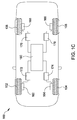
- Figure 1C illustrates an electric vehicle 160 that includes a respective electric motor (e.g., a hub motor) at each wheel.
- a first electric motor 162 drives the first front wheel 102
- a second electric motor 164 drives the second front wheel 104
- a third electric motor 166 drives the first rear wheel 106
- a fourth electric motor 168 drives the second rear wheel 108.
- Each electric motor is paired with one or more inverters (i.e., power controllers) to convert DC power from a battery 180 into AC power that is usable by the electric motor.
- the first electric motor 162 is connected to the first inverter(s) 172
- the second electric motor 164 is connected to the second inverter(s) 174
- the third electric motor 166 is connected to the third inverter(s) 176
- the fourth electric motor 168 is connected to the fourth inverter(s) 178.
- Power inverters are only rated to handle a particular amount of power. For example, suppose the battery 180 is capable of outputting 200 kW of power and, under ideal circumstances, each of the motors 162, 164, 166, and 168 is provided with 50 kW of power. Under such circumstances, power inverters that can handle 50 kW would be sufficient for each motor.
- the first power inverter 172, the second power inverter 174, the third power inverter 176, and the fourth power inverter 178 would each be able to handle 50 kW.
- one or more of the motors 162, 164, 166, and 168 may not be able to use the full 50 kW power output by the battery 180.
- environmental conditions such as ice under the rear wheels 106 and 108, could limit available traction.
- the motors 166 and 168 associated with the rear wheels 106 and 108 could have malfunctioned.
- the motors 162 and 164 associated with the front wheels 102 and 104 would be powered at their rated power (the other motors would either not be powered at all or would be powered at less than their rated power). In those cases where the rear motors 166 and 168 are not powered at all, the full 200 kW power would be available for the front motors 162 and 164. However, to use the full 200 kW of power the power inverter(s) 172 and 174 associated with each of the front wheels 102 and 104, respectively, would each have to be rated to handle 100 kW.
- a common group of power inverters are shared by multiple electric motors.
- a switching network is connected to the electric motors and to the power inverters to selectively couple different numbers of power inverters to the electric motors.
- PMC parallel modular converter
- FIG. 2A illustrates an electric vehicle 200 that includes a parallel modular converter (PMC) 202 to distribute electrical power to electric motors 152, 154, 156, and 158 at the wheels 102, 104, 106, and 108 of the electric vehicle 200.
- PMC parallel modular converter
- the PMC 202 includes a centralized group of parallel power converters (PPC) 208a, 208b, ..., 208n (i.e., power inverters) that are electrically connected in parallel, discussed in greater detail below.
- PPC parallel power converters
- the PMC 202 could include between two and twenty PPCs 208.
- the PMC 202 could include between five and ten PPCs 208.
- the PMC 202 also includes a power supply bus 206 and a switching network 204.
- the PPCs 208a, 208b, ..., 208n (208, collectively) are connected to the power supply bus 206, which, in turn, is connected to a power supply 210 (e.g., a battery, a fuel cell, or the like).
- a power supply 210 e.g., a battery, a fuel cell, or the like.
- the PPCs 208 are selectively connectable to the electric motors 152, 154, 156, and 158 by the switching network 204.
- the PMC 202 can also include and/or can be in communication with a controller 212.
- the controller 212 can control operation of the switches within the switching network, described below, and can also control operation of the PPCs.
- the PPCs 208 may be arranged as metal-oxide-semiconductor field-effect-transistor (MOSFET) and/or insulated gate bipolar transistor (IGBT) inverters using pulse width modulation for control.
- MOSFET metal-oxide-semiconductor field-effect-transistor
- IGBT insulated gate bipolar transistor
- the MOSFET inverter may operate at a significantly higher frequency.
- the transistors of the MOSFET inverter may operate at a frequency between 1 kHz and 1 MHz.
- the transistors of the MOSFET inverter may operate at a frequency between 3 kHz and 15 kHz.
- the transistors of the MOSFET inverter are switched on and off at varying ratios.
- the controller 212 can provide a master control signal (e.g., a pulse width modulation signal) to the PPCs 208.
- a master control signal e.g., a pulse width modulation signal
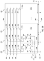
- FIG. 2B is a schematic view of the switching network 204 connected to the PPCs 208.
- the switching network 204 can include a first output power bus 220, a second output power bus 222, a third output power bus 224, and a fourth output power bus 226.
- the first output power bus 220 can be connected to the first electric motor 152 that drives the first front wheel 102 of the vehicle 200.
- the second output power bus 222 can be connected to the second electric motor 154 that drives the second front wheel 104 of the vehicle 200.
- the third output power bus 224 can be associated with the third electric motor 156 that drives the third wheel 106 of the vehicle 200.
- the fourth output power bus 226 can be associated with the fourth electric motor 158 that drives the fourth wheel 108 of the vehicle 200.
- the switching network 204 could include mechanical contactors and/or solid state relays.
- the PPCs 208 can be selectively connected to output power buses 220, 222, 224, and 226.
- the switching network 204 illustrated in Figure 2B includes a first array of selectable connections 230 used by a first PPC 208a, a second array of selectable connections 242 used by a second PPC 208b, a third array of selectable connections 254 used by a third PPC 208c, and an nth array of selectable connections 266 used by an nth PPC 208n.
- the first array of selectable connections 230 includes a first contact 234 that is electrically connected to the first output power bus 220, a second contact 236 that is electrically connected to the second output power bus 222, a third contact 238 that is electrically connected to the third output power bus 224, and a fourth contact 240 that is electrically connected to the fourth output power bus 226.
- the first array of selectable connections 230 could also include a null contact 232 that is not connected to any of the output power buses.
- a power output 214a from the first PPC 208a can be selectively connected to the first contact 234, the second contact 236, the third contact 238, or the fourth contact 240 by the controller 212 to couple the power output from the first PPC 208a to the first power bus 220, the second power bus 222, the third power bus 224, or the fourth power bus 226, respectively.
- the power output 214a from the first PPC 208a could be selectively connected to the null contact 232 by the controller 212 in the event power from the first PPC 208a is not needed at a particular moment.
- the second array of selectable connections 242 includes a first contact 246 that is electrically connected to the first output power bus 220, a second contact 248 that is electrically connected to the second output power bus 222, a third contact 250 that is electrically connected to the third output power bus 224, and a fourth contact 252 that is electrically connected to the fourth output power bus 226.
- the second array of selectable connections 242 could also include a null contact 244 that is not connected to any of the output power buses.
- a power output 214b from the second PPC 208b can be selectively connected to the first contact 246, the second contact 248, the third contact 250, or the fourth contact 252 by the controller 212 to couple the power output from the second PPC 208b to the first power bus 220, the second power bus 222, the third power bus 224, or the fourth power bus 226, respectively.
- the power output 214b from the second PPC 208b could be selectively connected to the null contact 244 by the controller 212 in the event power from the second PPC 208b is not needed at a particular moment.
- the third array of selectable connections 254 includes a first contact 258 that is electrically connected to the first output power bus 220, a second contact 260 that is electrically connected to the second output power bus 222, a third contact 262 that is electrically connected to the third output power bus 224, and a fourth contact 264 that is electrically connected to the fourth output power bus 226.
- the third array of selectable connections 254 could also include a null contact 256 that is not connected to any of the output power buses.
- a power output 214c from the third PPC 208c can be selectively connected to the first contact 258, the second contact 260, the third contact 262, or the fourth contact 264 by the controller 212 to couple the power output from the third PPC 208c to the first power bus 220, the second power bus 222, the third power bus 224, or the fourth power bus 226, respectively.
- the power output 214c from the third PPC 208c could be selectively connected to the null contact 256 by the controller 212 in the event power from the third PPC 208c is not needed at a particular moment.
- the nth array of selectable connections 266 includes a first contact 270 that is electrically connected to the first output power bus 220, a second contact 272 that is electrically connected to the second output power bus 222, a third contact 274 that is electrically connected to the third output power bus 224, and a fourth contact 276 that is electrically connected to the fourth output power bus 226.
- the nth array of selectable connections 254 could also include a null contact 268 that is not connected to any of the output power buses.
- a power output 214n from the nth PPC 208n can be selectively connected to the first contact 270, the second contact 272, the third contact 274, or the fourth contact 276 by the controller 212 to couple the power output from the nth PPC 208n to the first power bus 220, the second power bus 222, the third power bus 224, or the fourth power bus 226, respectively.
- the power output 214n from the nth PPC 208n could be selectively connected to the null contact 268 by the controller 212 in the event power from the nth PPC 208n is not needed at a particular moment.
- Figure 2B illustrates an exemplary scenario in which the power output 214a of the first PPC 208a is selectively connected to contact 234 on the first power bus 220 by the controller 212.
- Figure 2B also illustrates the power output 214b of the second PPC 208b selectively connected to contact 246 on the first power bus 220 by the controller 212, the power output 214c of the third PPC 208c selectively connected to contact 260 on the second power bus 222 by the controller 212, and the power output 214n of the nth PPC 208n selectively connected to the null contact 268 by the controller 212.
- Power outputs of PPCs that are not illustrated in Figure 2B could be connected to similar contacts to couple those power outputs to the various power buses and/or no connections.
- the first PPC 208a and the second PPC 208b are electrically connected in parallel to the first power bus 220.
- FIG 2B a simplified schematic circuit diagram for MOSFET-based power converters are shown.
- the circuitry could include circuitry for three-phase current operation, for example.
- the first PPC 208a includes a first MOSFET 280 and a second MOSFET 282.
- the first MOSFET 280 is electrically connected to the negative or ground terminal 294 of the DC power bus 290 from the power source 210.
- the second MOSFET 282 is electrically connected to the positive terminal 292 of the DC power bus 290.
- the first MOSFET 280 and the second MOSFET 282 are connected to a low pass filter 296, which is then connected to the power output 214a for the first PPC 208a.
- the second PPC 208b includes a third MOSFET 286 and a fourth MOSFET 288.
- the third MOSFET 286 is electrically connected to the negative or ground terminal 294 of the DC power bus 290 from the power source 210.
- the fourth MOSFET 288 is electrically connected to the positive terminal 292 of the DC power bus 290.
- the third MOSFET 286 and the fourth MOSFET 288 are connected to a low pass filter 298, which is then connected to the power output 214b for the second PPC 208b.
- the MOSFET circuits of the first PPC and the second PPC are electrically connected in parallel between the DC power bus 290 and the first power bus 220 in the illustrated exemplary scenario.
- the first MOSFET 280 and the third MOSFET 286 are electrically connected by a first communication channel 213 to the controller 212.
- the controller 212 can output a first pulse width modulation signal on the first communication channel 213 to cause the first MOSFET 280 and the third MOSFET 286 to open and close.
- the second MOSFET 282 and the fourth MOSFET 288 are electrically connected by a second communication channel 215 to the controller 212.
- the controller 212 can output a second pulse width modulation signal on the second communication channel 215 to cause the second MOSFET 282 and the fourth MOSFET 288 to open and close. Since the first MOSFET 280 and the third MOSFET 286 are connected to the same communication channel 213, the operation of the first MOSFET 280 and the third MOSFET 286 are synchronized by the first pulse width modulation signal such that the first MOSFET 280 and the third MOSFET 286 output power signals with the same waveform.
- each MOSFET could receive a dedicated pulse width modulation signal from the controller 212.
- the controller 212 could synchronize operation of a subset of the PPCs (e.g., PPCs that are connected to the same output power bus could be synchronized).
- the first power bus 220 can transmit the combined power output of the first PPC 208a and the second PPC 208b to the wheel motor 152 for the first front wheel 102 of the vehicle 200.
- the second power bus 222 is receiving power output from the third PPC 208c.
- the second power bus 222 can transmit the power output from the third PPC 208c to the wheel motor 154 for the second front wheel 104 of the vehicle 200.
- certain connections in the switching network 204 could be fixed or predetermined.
- one PPC could be permanently assigned to each of the wheel motors.
- the first PPC 208a could be permanently connected to the first power bus 220 (and therefore to the wheel motor 152 for the first front wheel 102).
- the second PPC 208b could be permanently connected to the second power bus 222 (and therefore to the wheel motor 154 for the second front wheel 104).
- the third PPC 208c could be permanently connected to the third power bus 224 (and therefore to the wheel motor 156 for the first rear wheel 106).
- a fourth PPC (e.g., a fourth PPC 208d that is not shown in Figure 2B ) could be permanently connected to the fourth power bus 226 (and therefore to the wheel motor 158 for the second rear wheel 108).
- Remaining PPCs (e.g., PPC 208n) could be selectively connected to the various power buses by the controller 212, as described above.
- certain PPCs in the switching network 204 could be limited to connecting to certain power buses.
- the first PPC 208a could be limited to only be selectively connectable to the first power bus 220 (via contact 234) or to the second power bus 222 (via contact 236).
- the contact 238 to the third power bus 224 and the contact 240 to the fourth power bus 226 could be omitted from the switch 204.
- the first PPC 208a would be selectively connectable to a power bus for the wheel motors 152 and 154 for the front wheels 102 and 104, respectively, of the vehicle 200.
- the second PPC 208b could be limited to only be selectively connectable to the third power bus 224 (via contact 250) or to the fourth power bus 226 (via contact 252).
- the contact 246 to the first power bus 220 and the contact 248 to the second power bus 222 could be omitted from the switch 204.
- the second PPC 208b would be selectively connectable to a power bus for the wheel motors 156 and 158 for the rear wheels 106 and 108, respectively, of the vehicle 200.
- the switch network 204 may be simplified.
- the switching network 204 can selectively connect the various PPCs 208 to the power buses 220, 222, 224, and 226 to provide power to the electric motors 152, 154, 156, and 158 based on load requests and/or environmental conditions.
- the switching network 204 can selectively connect the various PPCs 208 to the power buses 220, 222, 224, and 226 to provide power to the electric motors 152, 154, 156, and 158 based on load requests and/or environmental conditions.
- the switching network 204 can selectively connect the various PPCs 208 to the power buses 220, 222, 224, and 226 to provide power to the electric motors 152, 154, 156, and 158 based on load requests and/or environmental conditions.
- the PMC could include eight PPCs and, under steady-state driving conditions, each of the power buses in the switching network (that are connected to the electric motors 152, 154, 156, and 158) could be selectively connected to two of the eight PPCs.
- one of the two PPCs connected to a first power bus (connected to the electric motor 152 of the first front wheel 102) could be disconnected from the first power bus and selectively connected to a third power bus such that the power from that PPC is provided to the electric motor 156 of the first rear wheel 106.
- one of the two PPCs connected to a second power bus (connected to the electric motor 154 of the second front wheel 104) could be disconnected from the second power bus and selectively connected to a fourth power bus such that the power from that PPC is provided to the electric motor 158 of the second rear wheel 108.
- the electric motors 152, 154, 156, and 158 can act as power generators, providing electricity to recharge the power source 210.
- each of the electric motors 152, 154, 156, and 158 could provide AC power to the switching network and to the PPCs.
- the PPCs could convert the provided AC power to DC power, which is then provided to the power supply bus and then to the power supply.
- the distribution of the weight of the vehicle on the wheels 102, 104, 106, 108 shifts toward the front wheels 102 and 104. As a result, the front wheels 102 and 104 have more traction than the rear wheels 106 and 108.
- one of the two PPCs connected to the third power bus could be disconnected from the first power bus and selectively connected to the first power bus such that the power drawn from the electric motor 152 of the first front wheel 102 is provided to that PPC.
- one of the two PPCs connected to the fourth power bus could be disconnected from the fourth power bus and selectively connected to the second power bus such that the power drawn from the electric motor 154 of the second front wheel 104 is provided to that PPC.
- the PMC could selectively connect more PPCs to electric motors on the outside of a turn then on inside of a turn. For example, suppose the vehicle 200 is turning to the right. Continuing the example above in which the vehicle 200 includes eight PPCs, under such turning conditions, one of the two PPCs connected to the second power bus (connected to the electric motor 154 of the second front wheel 104) could be disconnected from the second power bus and selectively connected to the first power bus such that the power from that PPC is provided to the electric motor 152 of the first front wheel 102.
- one of the two PPCs connected to the fourth power bus could be disconnected from the fourth power bus and selectively connected to the third power bus such that the power from that PPC is provided to the electric motor 156 of the first rear wheel 106.
- a left turn could involve selectively connecting PPCs in a manner opposite to that described above with respect to the right hand turn.
- the PMC 202 can provide steering assistance to the vehicle 200.
- the switching network 204 could selectively connect a particular PPC to more than one power bus. For example, consider an exemplary scenario in which the vehicle 200 is moving very slowly in stop and go traffic. In such a scenario, a single PPC may satisfy the power requirements for the electric motors. The switching network 204 could simultaneously and selectively connect the first PPC 208a to the connection 234 for the first power bus 220, the connection 236 for the second power bus 222, the connection 238 for the third power bus 224, and connection 240 for the fourth power bus 226. The switching network 204 could leave the remaining PPCs disconnected (i.e., connected to the null connections).
- the power requirements of the vehicle 200 may be determined, in part, based on the extent to which a vehicle operator actuators a vehicle control, such as an accelerator pedal. In various aspects, the power requirements of the vehicle could be determined, in part, based on a selected mode of operation (e.g., city mode, performance mode, or the like).
- a selected mode of operation e.g., city mode, performance mode, or the like.
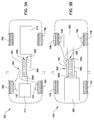
- FIG 3A illustrates an aspect in which a vehicle 300 is only driven by electric motors 152 and 154 at its front wheels 102 and 104, respectively.
- the electric motors 152 and 154 are connected to a PMC 302 that includes a switching network 304, a power supply bus 306, and PPCs 308.
- the power supply bus 306 is attached to a power source 310, such as a battery, a capacitor, a fuel cell, or the like.
- the PMC 302 can include and/or can be in communication with a controller 312.
- Figure 3B illustrates an aspect in which a vehicle 350 is only driven by electric motors 156 and 158 at its rear wheels 106 and 108, respectively.
- the electric motors 156 and 158 are connected to a PMC 352 that includes a switching network 354, a power supply bus 356, and PPCs 358.
- the power supply bus 356 is attached to a power source 360, such as the battery, capacitor, fuel cell, or the like.
- the PMC 352 can include and/or can be in communication with a controller 362.
- the switching networks 304 and 354 can be similar to the switching network 204, described above with respect to Figures 2A and 2B , except that the switching networks 304 and 354 only have a first power bus and a second power bus since there are only two electric motors in the respective vehicles.
- Control logic used by the controllers 312 and 362 to selectively connect various PPCs 308 and 358, respectively, to the first power bus and the second power bus could differ from control logic used by the controller 212 in Figures 2A .
- the vehicle 200 in Figure 2A has all four wheels being driven by electric motors, and certain PPCs may be selectively connected to certain motors based on weight transfer during acceleration or deceleration. Such weight transfer considerations may not be relevant in the front-wheel-drive only or rear-wheel-drive only vehicles 300 and 350 shown in Figures 3A and 3B , respectively.
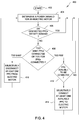
- FIG. 4 is a flowchart illustrating a method 400 for selectively connecting and/or disconnecting PPCs from an electric motor.
- the method 400 determines a load condition for an electric motor in block 404.
- the load condition of the electric motor could be an amount of power required to drive the electric motor or an amount of power that the electric motor is generating (e.g., during regenerative braking).
- the load condition of an electric motor could be affected by the acceleration, braking, and/or turning demands of the vehicle.
- the method 400 determines whether the PPCs connected to the electric motor satisfy the load condition. If the load condition is satisfied by the connected PPCs, then the method 400 returns to block 404.
- the method 400 moves to block 408 to determine whether there are too many PPCs connected to the electric motor were too few PPCs connected to the electric motor. There may be too many PPCs connected to the electric motor in the event that the total number of PPCs connected to the electric motor has more capacity than what the electric motor currently requires.
- an exemplary vehicle according to various aspects could include PPCs that are each rated to transmit 10 kW of electrical power. In an exemplary scenario, a particular electric motor of the vehicle may be demanding 22 kW of electrical power at a given moment. Thus, the particular electric motor would need to be connected to three PPCs.
- too many PPCs are selectively connected to the electric motor. There may also be too many PPCs connected to the electric motor in the event that the motor is outputting too much power (e.g., the wheel being driven by the motor is breaking traction with the ground) or in the event that the motor is being used for regenerative braking and is generating too much power (e.g., the wheel associated with the motor is beginning to skid). In such events, too many PPCs may be connected to the electric motor. If too many PPCs are connected to the electric motor, then the method 400 moves to block 410 and selectively disconnects at least one PPC from the electric motor. The method 400 then returns to block 404.
- too few PPCs may be connected to the electric motor.
- a vehicle includes PPCs that are each rated at 10 kW
- the electric motor is demanding 22 kW of power but is only selectively connected to two PPCs
- too few PPCs are connected to the electric motor.
- a third PPC needs to be selectively connected to the electric motor to provide the 22 kW of demanded power.
- the third PPC could be operated at a derated power setting to only provide the needed 2 kW of power needed from the third PPC.
- the electric motor may be providing 20 kW of regenerative braking if it is selectively connected to two of the 10 kW PPCs. However, the electric motor may be able to provide more regenerative braking if the wheel is not skidding. If a vehicle operator request more braking (i.e., more than the 20 kW of regenerative braking currently being provided), then too few PPCs are connected to the electric motor. In the event that too few PPCs are connected to the electric motor, then, in block 412, the method queries whether PPCs are available to be selectively connected to the electric motor.
- the method 400 If no PPCs are available to be selectively connected to the electric motor, then the method returns to block 404. If, in block 412, PPCs are available to be selectively connected to the electric motor, then, in block 414, the method 400 selectively connects at least one available PPC to the electric motor. The method 400 and returns to block 404.
- a vehicle includes 10 kW PPCs
- the power capacity of the PPCs could be unutilized.
- an electric motor with an operating demand of 22 kW of power would need three of the 10 kW PPCs to be selectively connected (e.g., 10 kW of power from a first PPC, 10 kW of power from a second PPC, and 2 kW from a third PPC operating at a derated power setting).
- 8 kW of capacity of the third PPC would not be utilized by the electric motor if the third PPC is only connected to the one electric motor.
- the PMC (e.g., PMC 202 in Figure 2A ) could operate at a very high frequency to switch PPCs between different power buses.
- the third PPC in this exemplary scenario could be selectively connected to multiple motors for varying times to distribute the power capacity of the third PPC. For example, suppose that the first electric motor is demanding 22 kW of power and a second electric motor is demanding 28 kW of power. A first two 10 kW PPCs could be selectively connected to the first electric motor to provide the first 20 kW of power to the first electric motor and a second two 10 kW PPCs could be selectively connected to the second electric motor to provide the first 20 kW of power to the second electric motor.
- a fifth 10 kW PPC could be selectively and sequentially connected to the first electric motor and the second electric motor in a repeating manner to provide the extra 2 kW and 8 kW of demanded power, respectively.
- the fifth PPC could be selectively connected to the first electric motor 20% of a particular time interval and to the second electric motor 80% of the particular time interval.
- the PMC can implement various vehicle safety and/or stability features, such as antilock braking, traction control, and/or stability control.
- antilock braking as discussed above, the electric motors 152, 154, 156, and 158 can provide regenerative braking by acting as generators that feed electrical power back to the power source 210.
- the controller could selectively reallocate capacity of the one or more PPCs from that electric motor to reduce the amount of power being drawn from the motor.
- the controller could selectively connect the one or more PPCs to the electric motor to restore the power being drawn from the electric motor.
- the controller could selectively connect and disconnect the PPCs to the particular electric motor many times per second (e.g., tens or hundreds of times per second) to improve traction while maximizing regenerative braking.
- the controller could selectively reallocate capacity one or more PPCs from the electric motor to reduce the amount of power being sent to that motor.
- the controller could selectively connect the one or more PPCs to the electric motor to restore power to the electric motor.
- the controller could selectively connect and disconnect the PPCs to the particular electric motor many times per second (e.g., tens or hundreds of times per second) to improve traction while maximizing the power output of the electric motors.
- vehicles often apply a particular brake and/or send power to a particular wheel to prevent a vehicle from sliding laterally (e.g., fish tailing).
- the PMC could selectively connect or disconnect PPCs from the electric motors associated with the wheels of the vehicle requiring more power and/or less power to control a lateral slide.
- first front wheel 102 could be reduced (or a regenerative braking force could be applied to the electric motor 152 associated with the first front wheel 102) and/or power could be applied to the electric motor 158 associated with the second rear wheel 108.
- the PMC could selectively disconnect PPCs 208 from the first power bus 220 to reduce power being sent to the first electric motor 152 associated with the first front wheel 102.
- the PMC could selectively connect PPCs 208 to the fourth power bus 226 to increase power being sent to the fourth electric motor 158 associated with the second rear wheel 108.
- a PMC such as PMC 202, PMC 302, and/or PMC 352 can be used in vehicles other than the four-wheel vehicles 200, 300, and 350, shown in Figures 2A , 3A, and 3B , respectively.
- a PMC could be used on a motorcycle that has electric motors driving the front wheel and the back wheel.
- a PMC could be used on a tractor-trailer.
- tractors powered by internal combustion engines often have two drive axles located behind the cab and a single steering axle in front of the cab. The internal combustion engine drive train could be removed and electric motors could be connected to the various wheels of the tractor.
- a PMC could be connected to the motors associated with the wheels on the two drive axles of the tractor.
- electric motors could also be added to the wheels associated with the steering axle, and the PMC could be connected to those motors as well.
- Tractor-trailer configurations typically include one or two axles arranged proximate to the rear end of the trailer. Typically, the wheels on these axles are not powered. However, in various aspects, electric motors could be added to the wheels of the trailer axle(s), and these electric motors could be connected to the PMC as well.
- a PMC such as PMC 202, PMC 302, and/or PMC 354, could be used in applications other than vehicles.
- a PMC could be used to drive electric motors (or other power sinks) associated with various air conditioners, hydraulic pumps, water pumps, refrigeration modules, blower units, or the like.
- a PMC could be used to drive electric motors for commercial building elevators.
- each set of power inverters must include sufficient power capacity to handle the maximum amount of power that would be sent to the motor.
- the vehicle 160 depicted in Figure 1C has a 100 kW power supply.
- each of the sets of inverters would need to have 100 kW of capacity.
- the inverter(s) 172 would have 100 kW of power capacity
- the inverter(s) 174 would have 100 kW of power capacity
- the inverter(s) 176 would have 100 kW of power capacity
- the inverter(s) 178 would have 100 kW of power capacity.
- the vehicle 160 would have a total of 400 kW of inverter power capacity if the vehicle 160 needs to be able to send all of the power from the power supply 160 to any one of the electric motors 162, 164, 166, and 168.
- the vehicle 200 depicted in Figure 2A could use the switching network 204 to electrically connect all of the power converters 208 to a single one of the electric motors 162, 164, 166, and 168.
- the vehicle 200 in Figure 2A could send all of the power from the power supply 210 to any one of the electric motors 162, 164, 166, and 168 with only a total of 100 kW of inverter power capacity. This reduction in required power inverter capacity could result in significant cost, complexity, and weight savings.
- aspects may take the form of an entirely hardware aspect, an entirely software aspect (including firmware, resident software, micro-code, etc.) or an aspect combining software and hardware aspects that may all generally be referred to herein as a "circuit,” “module” or “system.”
- the computer program product may include a computer readable storage medium (or media) having computer readable program instructions thereon for causing a processor to carry out aspects described herein.
- the computer readable storage medium can be a tangible device that can retain and store instructions for use by an instruction execution device.
- the computer readable storage medium may be, for example, but is not limited to, an electronic storage device, a magnetic storage device, an optical storage device, an electromagnetic storage device, a semiconductor storage device, or any suitable combination of the foregoing.
- a non-exhaustive list of more specific examples of the computer readable storage medium includes the following: a portable computer diskette, a hard disk, a random access memory (RAM), a read-only memory (ROM), an erasable programmable read-only memory (EPROM or Flash memory), a static random access memory (SRAM), a portable compact disc read-only memory (CD-ROM), a digital versatile disk (DVD), a memory stick, a floppy disk, a mechanically encoded device such as punch-cards or raised structures in a groove having instructions recorded thereon, and any suitable combination of the foregoing.
- RAM random access memory
- ROM read-only memory
- EPROM or Flash memory erasable programmable read-only memory
- SRAM static random access memory
- CD-ROM compact disc read-only memory
- DVD digital versatile disk
- memory stick a floppy disk
- a mechanically encoded device such as punch-cards or raised structures in a groove having instructions recorded thereon
- a computer readable storage medium is not to be construed as being transitory signals per se, such as radio waves or other freely propagating electromagnetic waves, electromagnetic waves propagating through a waveguide or other transmission media (e.g., light pulses passing through a fiber-optic cable), or electrical signals transmitted through a wire.
- Computer readable program instructions described herein can be downloaded to respective computing/processing devices from a computer readable storage medium or to an external computer or external storage device via a network, for example, the Internet, a local area network, a wide area network and/or a wireless network.
- the network may comprise copper transmission cables, optical transmission fibers, wireless transmission, routers, firewalls, switches, gateway computers and/or edge servers.
- a network adapter card or network interface in each computing/processing device receives computer readable program instructions from the network and forwards the computer readable program instructions for storage in a computer readable storage medium within the respective computing/processing device.
- Computer readable program instructions for carrying out operations of various aspects may be assembler instructions, instruction-set-architecture (ISA) instructions, machine instructions, machine dependent instructions, microcode, firmware instructions, state-setting data, or either source code or object code written in any combination of one or more programming languages, including an object oriented programming language such as Smalltalk, C++ or the like, and conventional procedural programming languages, such as the "C" programming language or similar programming languages.
- the computer readable program instructions may execute entirely on the user's computer, partly on the user's computer, as a stand-alone software package, partly on the user's computer and partly on a remote computer or entirely on the remote computer or server.
- the remote computer may be connected to the user's computer through any type of network, including a local area network (LAN) or a wide area network (WAN), or the connection may be made to an external computer (for example, through the Internet using an Internet Service Provider).
- electronic circuitry including, for example, programmable logic circuitry, field-programmable gate arrays (FPGA), or programmable logic arrays (PLA) may execute the computer readable program instructions by utilizing state information of the computer readable program instructions to personalize the electronic circuitry, in order to perform aspects.
- These computer readable program instructions may be provided to a processor of a general purpose computer, special purpose computer, or other programmable data processing apparatus to produce a machine, such that the instructions, which execute via the processor of the computer or other programmable data processing apparatus, create means for implementing the functions/acts specified in the flowchart and/or block diagram block or blocks.
- These computer readable program instructions may also be stored in a computer readable storage medium that can direct a computer, a programmable data processing apparatus, and/or other devices to function in a particular manner, such that the computer readable storage medium having instructions stored therein comprises an article of manufacture including instructions which implement aspects of the function/act specified in the flowchart and/or block diagram block or blocks.
- the computer readable program instructions may also be loaded onto a computer, other programmable data processing apparatus, or other device to cause a series of operational steps to be performed on the computer, other programmable apparatus or other device to produce a computer implemented process, such that the instructions which execute on the computer, other programmable apparatus, or other device implement the functions/acts specified in the flowchart and/or block diagram block or blocks.
- each block in the flowchart or block diagrams may represent a module, segment, or portion of instructions, which comprises one or more executable instructions for implementing the specified logical function(s).
- the functions noted in the block may occur out of the order noted in the Figures.
- two blocks shown in succession may, in fact, be executed substantially concurrently, or the blocks may sometimes be executed in the reverse order, depending upon the functionality involved.
Landscapes
- Engineering & Computer Science (AREA)
- Power Engineering (AREA)
- Transportation (AREA)
- Mechanical Engineering (AREA)
- Life Sciences & Earth Sciences (AREA)
- Sustainable Development (AREA)
- Sustainable Energy (AREA)
- Chemical & Material Sciences (AREA)
- Combustion & Propulsion (AREA)
- Electric Propulsion And Braking For Vehicles (AREA)
- Inverter Devices (AREA)
Applications Claiming Priority (1)
| Application Number | Priority Date | Filing Date | Title |
|---|---|---|---|
| US14/818,024 US10020759B2 (en) | 2015-08-04 | 2015-08-04 | Parallel modular converter architecture for efficient ground electric vehicles |
Publications (2)
| Publication Number | Publication Date |
|---|---|
| EP3127740A1 true EP3127740A1 (de) | 2017-02-08 |
| EP3127740B1 EP3127740B1 (de) | 2019-09-18 |
Family
ID=56740776
Family Applications (1)
| Application Number | Title | Priority Date | Filing Date |
|---|---|---|---|
| EP16177458.3A Active EP3127740B1 (de) | 2015-08-04 | 2016-07-01 | Parallele modulare wandlerarchitektur zur effizienten erdung von elektrofahrzeugen |
Country Status (4)
| Country | Link |
|---|---|
| US (1) | US10020759B2 (de) |
| EP (1) | EP3127740B1 (de) |
| JP (1) | JP6882863B2 (de) |
| CN (1) | CN106452278A (de) |
Cited By (1)
| Publication number | Priority date | Publication date | Assignee | Title |
|---|---|---|---|---|
| CN107264276A (zh) * | 2017-06-20 | 2017-10-20 | 北京智尊保汽车科技有限公司 | 两轮差速控制无级平衡标定方法 |
Families Citing this family (10)
| Publication number | Priority date | Publication date | Assignee | Title |
|---|---|---|---|---|
| DE102016215834A1 (de) * | 2016-08-23 | 2018-03-01 | Continental Teves Ag & Co. Ohg | Verfahren zum Betreiben einer Druckregelvorrichtung sowie Druckregelvorrichtung zur Durchführung des Verfahrens |
| US11130537B1 (en) * | 2017-12-13 | 2021-09-28 | Michael Major, Jr. | System and method for repowering a personal transport vehicle to convert from electric motor power to internal combustion engine power |
| DE102019209280A1 (de) * | 2019-06-26 | 2020-12-31 | Robert Bosch Gmbh | Fahrzeug und Verfahren zum Betreiben eines Fahrzeuges |
| CN116490394A (zh) * | 2020-10-13 | 2023-07-25 | 海易森汽车股份有限公司 | 具有超级电容器的模块化升压转换器系统 |
| EP4024649A1 (de) | 2020-12-29 | 2022-07-06 | Goodrich Control Systems | Verteilte steuerungsarchitektur für motorantriebe |
| EP4044424B1 (de) | 2021-02-12 | 2026-04-01 | Collins Aerospace Ireland, Limited | Strukturen zur steuerung von einzelereignisverzerrungen für parallel antriebssteuerungsarchitekturen von motoren |
| US11485215B1 (en) | 2021-12-09 | 2022-11-01 | Workhorse Group Inc. | Land vehicles incorporating electric motors and methods therefor |
| CN115848161B (zh) * | 2022-12-06 | 2024-12-13 | 中国重汽集团济南动力有限公司 | 一种双轴驱动的电驱桥车辆及多电机控制系统、方法及车辆 |
| DE102023113644A1 (de) | 2023-05-24 | 2024-11-28 | Dr. Ing. H.C. F. Porsche Aktiengesellschaft | Antriebssystem für ein Elektrofahrzeug |
| US20250279487A1 (en) * | 2024-03-04 | 2025-09-04 | Volvo Car Corporation | Partitioning a battery array for dedicated powering of in-wheel electric machines |
Citations (6)
| Publication number | Priority date | Publication date | Assignee | Title |
|---|---|---|---|---|
| EP0409226A2 (de) * | 1989-07-21 | 1991-01-23 | Hitachi, Ltd. | Steuersystem für Energieversorgungsquelle |
| EP1921742A2 (de) * | 2006-11-09 | 2008-05-14 | Honeywell International, Inc. | Modulares, skalierbares Stromrichtersystem für ein Flugzeug |
| US20100013419A1 (en) * | 2008-07-18 | 2010-01-21 | Jeffrey Joseph White | Parallel Motor Controller Architecture |
| US20110307129A1 (en) * | 2010-06-10 | 2011-12-15 | Ford Global Technologies, Llc | Vehicle steerability and stability control via independent wheel torque control |
| EP2777974A2 (de) * | 2013-03-15 | 2014-09-17 | General Electric Company | Elektrofahrzeug mit verbessertem elektrischem Antriebssystem |
| EP2942679A2 (de) * | 2014-04-29 | 2015-11-11 | The Boeing Company | Systeme und Verfahren zur Steuerung und Bedienung einer parallelen Motorsteuerungsarchitektur |
Family Cites Families (99)
| Publication number | Priority date | Publication date | Assignee | Title |
|---|---|---|---|---|
| US3254302A (en) | 1963-07-18 | 1966-05-31 | Westinghouse Electric Corp | Push-pull parallel amplifier including current balancing means |
| US3675114A (en) | 1971-06-14 | 1972-07-04 | Forbro Design Corp | High current voltage/current regulator employing a plurality of parallel connected power transistors |
| DE2951708A1 (de) | 1979-12-19 | 1981-07-02 | Schering Ag Berlin Und Bergkamen, 1000 Berlin | Verfahren und vorrichtung zur automatischen regelung von teilstromstaerken eines gleichrichters |
| US4717833A (en) | 1984-04-30 | 1988-01-05 | Boschert Inc. | Single wire current share paralleling of power supplies |
| US4616142A (en) | 1984-12-31 | 1986-10-07 | Sundstrand Corporation | Method of operating parallel-connected semiconductor switch elements |
| US4863021A (en) | 1988-05-06 | 1989-09-05 | Macmillan Bloedel Limited | Bulk bin bag cassette |
| US4877972A (en) | 1988-06-21 | 1989-10-31 | The Boeing Company | Fault tolerant modular power supply system |
| WO1990013178A1 (en) | 1989-04-19 | 1990-11-01 | Sundstrand Corporation | Gate drive circuit for power transistor |
| US5208485A (en) | 1991-10-24 | 1993-05-04 | The Boeing Company | Apparatus for controlling current through a plurality of resistive loads |
| US5434527A (en) | 1993-10-25 | 1995-07-18 | Caterpillar Inc. | Gate drive circuit |
| US6792337B2 (en) | 1994-12-30 | 2004-09-14 | Power Measurement Ltd. | Method and system for master slave protocol communication in an intelligent electronic device |
| US5592394A (en) | 1995-01-31 | 1997-01-07 | Dell U.S.A., L.P. | FET current sensor for active balancing or regulating circuits |
| JP3267189B2 (ja) | 1997-05-14 | 2002-03-18 | 富士電機株式会社 | 電力変換装置のデバイス定常電流バランス制御回路 |
| US5939802A (en) | 1997-12-22 | 1999-08-17 | Rantec Microwave & Electronic, Inc. | Automatic bus transfer device for single phase and multiphase power systems, providing infinite isolation |
| US6272023B1 (en) | 1999-05-15 | 2001-08-07 | Technical Witts, Inc | High efficiency coupled inductor soft switching power converters |
| US6147886A (en) | 1999-05-15 | 2000-11-14 | Technical Witts, Inc. | Dual opposed interleaved coupled inductor soft switching converters |
| US6278263B1 (en) | 1999-09-01 | 2001-08-21 | Intersil Corporation | Multi-phase converter with balanced currents |
| JP2001228941A (ja) | 2000-02-16 | 2001-08-24 | Internatl Business Mach Corp <Ibm> | 電源装置及びコンピュータ |
| US8008901B2 (en) | 2006-02-28 | 2011-08-30 | Infineon Technologies Austria Ag | Regulated power supply with multiple regulators sharing the total current supplied to a load |
| JP2003153588A (ja) * | 2001-11-09 | 2003-05-23 | Nissan Motor Co Ltd | モータ駆動装置 |
| EP1320167A1 (de) | 2001-12-13 | 2003-06-18 | Magnetek S.p.A. | Verfahren und Schaltung zur Stromaufteilung einer modularen Stromversorgung |
| US6674325B2 (en) | 2002-05-14 | 2004-01-06 | Windbond Electronics Corporation | Balanced current converter with multiple pulse width modulated channels |
| US6534960B1 (en) | 2002-06-18 | 2003-03-18 | Texas Instruments Incorporated | Multi-channel interleaved power converter with current sharing |
| US6806772B2 (en) | 2002-11-06 | 2004-10-19 | Itt Manufacturing Enterprises, Inc. | Power transistor array temperature control system |
| KR20060060018A (ko) | 2003-08-12 | 2006-06-02 | 코닌클리즈케 필립스 일렉트로닉스 엔.브이. | 전자 회로, 제 1 및 제 2 mosfet의 동작 방법 |
| WO2005069221A1 (ja) | 2004-01-15 | 2005-07-28 | Nec Corporation | パターン識別システム、パターン識別方法、及びパターン識別プログラム |
| US7265601B2 (en) | 2004-08-23 | 2007-09-04 | International Rectifier Corporation | Adaptive gate drive voltage circuit |
| US7465507B2 (en) | 2004-09-21 | 2008-12-16 | Genesis Fueltech, Inc. | Portable fuel cell system with releasable and rechargeable batteries |
| US7521985B2 (en) | 2005-07-01 | 2009-04-21 | Semiconductor Components Industries, L.L.C. | Method for regulating temperature and circuit therefor |
| US7745025B2 (en) | 2006-02-14 | 2010-06-29 | Mti Microfuel Cells Inc. | Fuel cell based rechargable power pack system and associated methods for controlling same |
| US7423894B2 (en) | 2006-03-03 | 2008-09-09 | Advanced Energy Industries, Inc. | Interleaved soft switching bridge power converter |
| US9461552B2 (en) | 2006-03-23 | 2016-10-04 | Enphase Energy, Inc. | Method and apparatus for power conversion |
| KR101205279B1 (ko) | 2006-03-23 | 2012-11-27 | 엔페이즈 에너지, 인코포레이티드 | 직류를 교류로 변환하는 방법 및 장치 |
| US9436198B2 (en) | 2006-03-23 | 2016-09-06 | Enphase Energy, Inc. | Method and apparatus for power conversion |
| JP4379430B2 (ja) | 2006-04-24 | 2009-12-09 | トヨタ自動車株式会社 | 電源システムおよび車両 |
| FR2900635B1 (fr) | 2006-05-05 | 2008-07-25 | Hispano Suiza Sa | Systeme d'alimentation et de commande d'equipements electriques d'un moteur d'aeronef ou de son environnement |
| US7832513B2 (en) * | 2006-07-14 | 2010-11-16 | Gm Global Technology Operations, Inc. | Vehicular electrical system and control method therefor |
| JP4155321B2 (ja) * | 2006-09-25 | 2008-09-24 | トヨタ自動車株式会社 | ハイブリッド車両の表示装置、ハイブリッド車両、およびハイブリッド車両の表示方法 |
| FR2907760B1 (fr) | 2006-10-25 | 2009-06-12 | Airbus France Sas | Systeme et procede d'alimentation en puissance a bord d'un aeronef. |
| WO2008136094A1 (ja) * | 2007-04-24 | 2008-11-13 | Mitsubishi Electric Corporation | 電気駆動システムおよびハイブリット駆動システム |
| EP2225118B1 (de) | 2007-12-12 | 2016-06-22 | Foss Maritime Company | Hybridantriebssysteme |
| US9263895B2 (en) | 2007-12-21 | 2016-02-16 | Sunpower Corporation | Distributed energy conversion systems |
| US7872886B2 (en) | 2008-02-20 | 2011-01-18 | Virginia Tech Intellectual Properties, Inc. | Quasi-parallel voltage regulator |
| JP2010051092A (ja) * | 2008-08-21 | 2010-03-04 | Toyota Motor Corp | 充電システムおよびそれを備えた車両 |
| JP2010075036A (ja) * | 2008-08-22 | 2010-04-02 | Fuji Heavy Ind Ltd | 電気自動車の制御装置 |
| CN102186710B (zh) * | 2008-10-14 | 2013-11-20 | 丰田自动车株式会社 | 混合动力车辆的控制装置和控制方法 |
| JP4572979B2 (ja) * | 2008-10-21 | 2010-11-04 | トヨタ自動車株式会社 | 電源システムおよびそれを備えた車両、ならびに電源システムの制御方法 |
| CN102196940B (zh) * | 2008-10-31 | 2013-09-25 | 丰田自动车株式会社 | 电动车辆的电源系统及其控制方法 |
| JP5141772B2 (ja) * | 2008-10-31 | 2013-02-13 | トヨタ自動車株式会社 | 電動車両の電源システムおよびその制御方法 |
| JP5099229B2 (ja) * | 2008-10-31 | 2012-12-19 | トヨタ自動車株式会社 | ハイブリッド車両およびその制御方法 |
| RU2480348C2 (ru) * | 2008-12-22 | 2013-04-27 | Тойота Дзидося Кабусики Кайся | Гибридное транспортное средство |
| JP5195923B2 (ja) * | 2008-12-24 | 2013-05-15 | アイシン・エィ・ダブリュ株式会社 | ハイブリッド駆動装置 |
| US8125200B2 (en) | 2009-04-29 | 2012-02-28 | Dell Products L.P. | Systems and methods for intelligently optimizing operating efficiency using variable gate drive voltage |
| TWI379483B (en) | 2009-07-07 | 2012-12-11 | Delta Electronics Inc | Current balance power supplying circuit for plural sets of dc loads |
| US8310272B2 (en) * | 2009-07-29 | 2012-11-13 | GM Global Technology Operations LLC | Method and system for testing electric automotive drive systems |
| US8508166B2 (en) | 2009-08-10 | 2013-08-13 | Emerson Climate Technologies, Inc. | Power factor correction with variable bus voltage |
| US8359131B2 (en) * | 2010-03-25 | 2013-01-22 | GM Global Technology Operations LLC | Method and system for operating an electric motor |
| JP2011229286A (ja) * | 2010-04-20 | 2011-11-10 | Nobuyoshi Muto | 電気自動車およびプログラム |
| WO2011161865A1 (ja) | 2010-06-25 | 2011-12-29 | パナソニック株式会社 | リチウムイオン二次電池の充電方法及び充電システム |
| US9577424B2 (en) | 2010-07-16 | 2017-02-21 | Rockwell Automation Technologies, Inc. | Parallel motor drive disable verification system and method |
| WO2012026026A1 (ja) * | 2010-08-26 | 2012-03-01 | 三菱電機株式会社 | 車両用制御装置およびディーゼルハイブリッド車両システム |
| US8797773B2 (en) * | 2010-08-30 | 2014-08-05 | Cooper Technologies Company | Isolated DC-DC converter including ZVS full-bridge and current doubler |
| US8736102B1 (en) | 2010-10-07 | 2014-05-27 | The Boeing Company | Multifunctional power converter |
| EP2445110B1 (de) | 2010-10-22 | 2014-05-14 | ABB Research Ltd | Gate-Treibereinheit für eine elektrische Schaltvorrichtung |
| US9013066B2 (en) | 2010-10-28 | 2015-04-21 | Honeywell International Inc. | High voltage electric accumulators with internal distributed DC-DC converters for self regulation and protection |
| US8432104B2 (en) | 2010-12-09 | 2013-04-30 | Delta Electronics, Inc. | Load current balancing circuit |
| EP2660581B1 (de) * | 2010-12-30 | 2016-04-06 | Fundacion Tecnalia Research & Innovation | System zum testen und zur evaluierung der leistung und energieeffizienz des antriebssystems eines hybrid-elektrofahrzeuges. |
| KR101217074B1 (ko) | 2011-02-21 | 2012-12-31 | 로베르트 보쉬 게엠베하 | 배터리 관리 시스템 |
| US8738268B2 (en) | 2011-03-10 | 2014-05-27 | The Boeing Company | Vehicle electrical power management and distribution |
| CN103415989A (zh) | 2011-03-16 | 2013-11-27 | 丰田自动车株式会社 | 变换器的过热保护控制装置和变换器的过热保护控制方法 |
| US8611107B2 (en) | 2011-04-27 | 2013-12-17 | Solarbridge Technologies, Inc. | Method and system for controlling a multi-stage power inverter |
| KR101939662B1 (ko) | 2011-06-14 | 2019-01-18 | 인피니언 테크놀로지스 오스트리아 아게 | 전력 트랜지스터 게이트 드라이버 |
| US9086333B2 (en) * | 2011-06-16 | 2015-07-21 | Horiba Instruments Incorporated | Examination system for electric vehicle or hybrid electric vehicle |
| US8829826B2 (en) * | 2011-08-25 | 2014-09-09 | Hamilton Sundstrand Corporation | Regenerative load electric power management systems and methods |
| US8792253B2 (en) | 2011-10-03 | 2014-07-29 | The Boeing Company | System and methods for high power DC/DC converter |
| US9065321B2 (en) | 2011-12-22 | 2015-06-23 | Varentec, Inc. | Isolated dynamic current converters |
| WO2013138219A1 (en) | 2012-03-12 | 2013-09-19 | Board Of Trustees Of Michigan State University | High efficiency gate drive circuit for power transistors |
| US9302912B2 (en) | 2012-03-28 | 2016-04-05 | Mks Instruments, Inc. | Compact, configurable power supply for energizing ozone-producing cells |
| US8972765B1 (en) * | 2012-04-04 | 2015-03-03 | The Boeing Company | Electrical energy management method and apparatus for multiple distribution buses and batteries |
| WO2014025734A2 (en) | 2012-08-09 | 2014-02-13 | Danfoss Power Electronics A/S | Modular inverter drive |
| WO2014026124A1 (en) | 2012-08-10 | 2014-02-13 | Emerson Climate Technologies, Inc. | Motor drive control using pulse-width modulation pulse skipping |
| CN103707748B (zh) * | 2012-09-28 | 2017-03-01 | 通用电气公司 | 功率传输系统和驱动系统 |
| US8964432B2 (en) | 2013-01-29 | 2015-02-24 | The Boeing Company | Apparatus and method for controlling circulating current in an inverter system |
| US9391540B2 (en) | 2013-02-12 | 2016-07-12 | Enphase Energy, Inc. | Method and apparatus for chaotic democratic pulse width modulation generation |
| US9130482B2 (en) | 2013-02-20 | 2015-09-08 | Infineon Technologies Ag | Pseudo zero vectors for space vector modulation and enhanced space vector modulation |
| US9178485B2 (en) | 2013-03-06 | 2015-11-03 | Regal Beloit America, Inc. | Methods and systems for reducing conducted electromagnetic interference |
| US9048726B1 (en) | 2013-03-11 | 2015-06-02 | The Boeing Company | Power system having repetitive control in symmetric sequences with harmonics cancellation |
| EP3006291B1 (de) * | 2013-05-29 | 2018-05-16 | Nissan Motor Co., Ltd | Steuerungsvorrichtung für ein pulg-in-hybridfahrzeug |
| JP5780269B2 (ja) * | 2013-07-12 | 2015-09-16 | トヨタ自動車株式会社 | 電力供給システムおよび受電設備 |
| US9533638B2 (en) * | 2013-07-18 | 2017-01-03 | The Boeing Company | Aircraft universal power converter |
| US9804613B2 (en) * | 2013-07-22 | 2017-10-31 | The Boeing Company | Parallel transistor circuit controller |
| JP5958436B2 (ja) * | 2013-08-26 | 2016-08-02 | トヨタ自動車株式会社 | 車両 |
| EP3055916B1 (de) | 2013-10-07 | 2018-08-01 | Garrity Power Services LLC | Smart-grid-stromwandler |
| US9634596B2 (en) * | 2013-10-09 | 2017-04-25 | Michael H Gurin | Hybrid power generation with variable voltage flux |
| JP5949731B2 (ja) * | 2013-11-18 | 2016-07-13 | トヨタ自動車株式会社 | ハイブリッド車両 |
| US9046912B1 (en) | 2014-02-24 | 2015-06-02 | The Boeing Company | Thermally balanced parallel operation of transistors |
| EP2928038A1 (de) | 2014-03-31 | 2015-10-07 | ABB Technology AG | Induktives Stromübertragungssystem und Verfahren zum Betreiben eines induktiven Energietransfersystems |
| US10079493B2 (en) | 2014-09-30 | 2018-09-18 | The Boeing Company | Parallel modular converter architecture |
| US9647455B2 (en) | 2014-09-30 | 2017-05-09 | The Boeing Company | EMI filter systems and methods for parallel modular converters |
-
2015
- 2015-08-04 US US14/818,024 patent/US10020759B2/en active Active
-
2016
- 2016-07-01 EP EP16177458.3A patent/EP3127740B1/de active Active
- 2016-07-06 CN CN201610525425.3A patent/CN106452278A/zh active Pending
- 2016-07-26 JP JP2016145961A patent/JP6882863B2/ja active Active
Patent Citations (6)
| Publication number | Priority date | Publication date | Assignee | Title |
|---|---|---|---|---|
| EP0409226A2 (de) * | 1989-07-21 | 1991-01-23 | Hitachi, Ltd. | Steuersystem für Energieversorgungsquelle |
| EP1921742A2 (de) * | 2006-11-09 | 2008-05-14 | Honeywell International, Inc. | Modulares, skalierbares Stromrichtersystem für ein Flugzeug |
| US20100013419A1 (en) * | 2008-07-18 | 2010-01-21 | Jeffrey Joseph White | Parallel Motor Controller Architecture |
| US20110307129A1 (en) * | 2010-06-10 | 2011-12-15 | Ford Global Technologies, Llc | Vehicle steerability and stability control via independent wheel torque control |
| EP2777974A2 (de) * | 2013-03-15 | 2014-09-17 | General Electric Company | Elektrofahrzeug mit verbessertem elektrischem Antriebssystem |
| EP2942679A2 (de) * | 2014-04-29 | 2015-11-11 | The Boeing Company | Systeme und Verfahren zur Steuerung und Bedienung einer parallelen Motorsteuerungsarchitektur |
Cited By (1)
| Publication number | Priority date | Publication date | Assignee | Title |
|---|---|---|---|---|
| CN107264276A (zh) * | 2017-06-20 | 2017-10-20 | 北京智尊保汽车科技有限公司 | 两轮差速控制无级平衡标定方法 |
Also Published As
| Publication number | Publication date |
|---|---|
| US20170040915A1 (en) | 2017-02-09 |
| EP3127740B1 (de) | 2019-09-18 |
| JP6882863B2 (ja) | 2021-06-02 |
| US10020759B2 (en) | 2018-07-10 |
| JP2017077154A (ja) | 2017-04-20 |
| CN106452278A (zh) | 2017-02-22 |
Similar Documents
| Publication | Publication Date | Title |
|---|---|---|
| EP3127740B1 (de) | Parallele modulare wandlerarchitektur zur effizienten erdung von elektrofahrzeugen | |
| CN110525235B (zh) | 车辆的电源系统 | |
| CN107206887B (zh) | 具有布置在车辆的多个独立部分中的多个驱动单元的电动或混合动力车辆 | |
| CN103786728B (zh) | 用于控制电动四驱混合动力电动车的系统和其方法 | |
| RU2752149C1 (ru) | Система и способ подачи электрической энергии к транспортному средству для горных работ и транспортное средство для горных работ | |
| US10538163B2 (en) | Apparatus and method for failsafe in electric corner module system | |
| CN103237706A (zh) | 混合电动车辆 | |
| US6958587B1 (en) | Torque distribution for multiple propulsion system vehicles | |
| US12508894B2 (en) | Control method of four-wheel drive system with boosting operation | |
| CN111301196A (zh) | 电动车辆和充电系统 | |
| CN104709102B (zh) | 电动汽车电池组单元通断与电动机驱动系统及其控制方法 | |
| CN109843626B (zh) | 混合动力车辆 | |
| JP2015523257A (ja) | 絶縁接触器による過渡的極性制御 | |
| KR20240092676A (ko) | 전동화 차량 및 그를 위한 제어 방법 | |
| KR20170070211A (ko) | 제1 동력 공급 경로에서 제2 동력 공급 경로로 전환하기 위한 방법 및 시스템 | |
| CN115230484B (zh) | 控制组件及驱动系统 | |
| CN111267596A (zh) | 一种电动汽车驱动装置、系统以及电动汽车 | |
| US12388272B2 (en) | Balancing of battery packs via DC-to-DC converters and motor inverter circuits | |
| JP5277433B2 (ja) | 電動車両の駆動装置 | |
| JP2015167448A (ja) | 車両用モータ装置 | |
| US20240253519A1 (en) | High-voltage vehicle system | |
| KR20250170843A (ko) | 전동식 브레이크 시스템의 전원 공급장치 및 공급방법 | |
| CN207875415U (zh) | 一种四驱电动汽车的双动力源系统 | |
| JP2015107689A (ja) | ハイブリッド車両及びその制御方法 | |
| CN108099664A (zh) | 一种四驱电动汽车的双动力源系统 |
Legal Events
| Date | Code | Title | Description |
|---|---|---|---|
| PUAI | Public reference made under article 153(3) epc to a published international application that has entered the european phase |
Free format text: ORIGINAL CODE: 0009012 |
|
| STAA | Information on the status of an ep patent application or granted ep patent |
Free format text: STATUS: REQUEST FOR EXAMINATION WAS MADE |
|
| 17P | Request for examination filed |
Effective date: 20160701 |
|
| AK | Designated contracting states |
Kind code of ref document: A1 Designated state(s): AL AT BE BG CH CY CZ DE DK EE ES FI FR GB GR HR HU IE IS IT LI LT LU LV MC MK MT NL NO PL PT RO RS SE SI SK SM TR |
|
| AX | Request for extension of the european patent |
Extension state: BA ME |
|
| RBV | Designated contracting states (corrected) |
Designated state(s): AL AT BE BG CH CY CZ DE DK EE ES FI FR GB GR HR HU IE IS IT LI LT LU LV MC MK MT NL NO PL PT RO RS SE SI SK SM TR |
|
| REG | Reference to a national code |
Ref country code: DE Ref legal event code: R079 Ref document number: 602016020711 Country of ref document: DE Free format text: PREVIOUS MAIN CLASS: B60L0011180000 Ipc: B60L0050500000 |
|
| GRAP | Despatch of communication of intention to grant a patent |
Free format text: ORIGINAL CODE: EPIDOSNIGR1 |
|
| STAA | Information on the status of an ep patent application or granted ep patent |
Free format text: STATUS: GRANT OF PATENT IS INTENDED |
|
| RIC1 | Information provided on ipc code assigned before grant |
Ipc: B60L 50/50 20190101AFI20190312BHEP |
|
| INTG | Intention to grant announced |
Effective date: 20190401 |
|
| GRAS | Grant fee paid |
Free format text: ORIGINAL CODE: EPIDOSNIGR3 |
|
| GRAA | (expected) grant |
Free format text: ORIGINAL CODE: 0009210 |
|
| STAA | Information on the status of an ep patent application or granted ep patent |
Free format text: STATUS: THE PATENT HAS BEEN GRANTED |
|
| AK | Designated contracting states |
Kind code of ref document: B1 Designated state(s): AL AT BE BG CH CY CZ DE DK EE ES FI FR GB GR HR HU IE IS IT LI LT LU LV MC MK MT NL NO PL PT RO RS SE SI SK SM TR |
|
| REG | Reference to a national code |
Ref country code: GB Ref legal event code: FG4D |
|
| REG | Reference to a national code |
Ref country code: CH Ref legal event code: EP |
|
| REG | Reference to a national code |
Ref country code: DE Ref legal event code: R096 Ref document number: 602016020711 Country of ref document: DE |
|
| REG | Reference to a national code |
Ref country code: AT Ref legal event code: REF Ref document number: 1180873 Country of ref document: AT Kind code of ref document: T Effective date: 20191015 |
|
| REG | Reference to a national code |
Ref country code: IE Ref legal event code: FG4D |
|
| REG | Reference to a national code |
Ref country code: NL Ref legal event code: MP Effective date: 20190918 |
|
| PG25 | Lapsed in a contracting state [announced via postgrant information from national office to epo] |
Ref country code: HR Free format text: LAPSE BECAUSE OF FAILURE TO SUBMIT A TRANSLATION OF THE DESCRIPTION OR TO PAY THE FEE WITHIN THE PRESCRIBED TIME-LIMIT Effective date: 20190918 Ref country code: BG Free format text: LAPSE BECAUSE OF FAILURE TO SUBMIT A TRANSLATION OF THE DESCRIPTION OR TO PAY THE FEE WITHIN THE PRESCRIBED TIME-LIMIT Effective date: 20191218 Ref country code: NO Free format text: LAPSE BECAUSE OF FAILURE TO SUBMIT A TRANSLATION OF THE DESCRIPTION OR TO PAY THE FEE WITHIN THE PRESCRIBED TIME-LIMIT Effective date: 20191218 Ref country code: LT Free format text: LAPSE BECAUSE OF FAILURE TO SUBMIT A TRANSLATION OF THE DESCRIPTION OR TO PAY THE FEE WITHIN THE PRESCRIBED TIME-LIMIT Effective date: 20190918 Ref country code: FI Free format text: LAPSE BECAUSE OF FAILURE TO SUBMIT A TRANSLATION OF THE DESCRIPTION OR TO PAY THE FEE WITHIN THE PRESCRIBED TIME-LIMIT Effective date: 20190918 Ref country code: SE Free format text: LAPSE BECAUSE OF FAILURE TO SUBMIT A TRANSLATION OF THE DESCRIPTION OR TO PAY THE FEE WITHIN THE PRESCRIBED TIME-LIMIT Effective date: 20190918 |
|
| REG | Reference to a national code |
Ref country code: LT Ref legal event code: MG4D |
|
| PG25 | Lapsed in a contracting state [announced via postgrant information from national office to epo] |
Ref country code: RS Free format text: LAPSE BECAUSE OF FAILURE TO SUBMIT A TRANSLATION OF THE DESCRIPTION OR TO PAY THE FEE WITHIN THE PRESCRIBED TIME-LIMIT Effective date: 20190918 Ref country code: GR Free format text: LAPSE BECAUSE OF FAILURE TO SUBMIT A TRANSLATION OF THE DESCRIPTION OR TO PAY THE FEE WITHIN THE PRESCRIBED TIME-LIMIT Effective date: 20191219 Ref country code: LV Free format text: LAPSE BECAUSE OF FAILURE TO SUBMIT A TRANSLATION OF THE DESCRIPTION OR TO PAY THE FEE WITHIN THE PRESCRIBED TIME-LIMIT Effective date: 20190918 Ref country code: AL Free format text: LAPSE BECAUSE OF FAILURE TO SUBMIT A TRANSLATION OF THE DESCRIPTION OR TO PAY THE FEE WITHIN THE PRESCRIBED TIME-LIMIT Effective date: 20190918 |
|
| REG | Reference to a national code |
Ref country code: AT Ref legal event code: MK05 Ref document number: 1180873 Country of ref document: AT Kind code of ref document: T Effective date: 20190918 |
|
| PG25 | Lapsed in a contracting state [announced via postgrant information from national office to epo] |
Ref country code: RO Free format text: LAPSE BECAUSE OF FAILURE TO SUBMIT A TRANSLATION OF THE DESCRIPTION OR TO PAY THE FEE WITHIN THE PRESCRIBED TIME-LIMIT Effective date: 20190918 Ref country code: IT Free format text: LAPSE BECAUSE OF FAILURE TO SUBMIT A TRANSLATION OF THE DESCRIPTION OR TO PAY THE FEE WITHIN THE PRESCRIBED TIME-LIMIT Effective date: 20190918 Ref country code: EE Free format text: LAPSE BECAUSE OF FAILURE TO SUBMIT A TRANSLATION OF THE DESCRIPTION OR TO PAY THE FEE WITHIN THE PRESCRIBED TIME-LIMIT Effective date: 20190918 Ref country code: PT Free format text: LAPSE BECAUSE OF FAILURE TO SUBMIT A TRANSLATION OF THE DESCRIPTION OR TO PAY THE FEE WITHIN THE PRESCRIBED TIME-LIMIT Effective date: 20200120 Ref country code: AT Free format text: LAPSE BECAUSE OF FAILURE TO SUBMIT A TRANSLATION OF THE DESCRIPTION OR TO PAY THE FEE WITHIN THE PRESCRIBED TIME-LIMIT Effective date: 20190918 Ref country code: PL Free format text: LAPSE BECAUSE OF FAILURE TO SUBMIT A TRANSLATION OF THE DESCRIPTION OR TO PAY THE FEE WITHIN THE PRESCRIBED TIME-LIMIT Effective date: 20190918 Ref country code: NL Free format text: LAPSE BECAUSE OF FAILURE TO SUBMIT A TRANSLATION OF THE DESCRIPTION OR TO PAY THE FEE WITHIN THE PRESCRIBED TIME-LIMIT Effective date: 20190918 Ref country code: ES Free format text: LAPSE BECAUSE OF FAILURE TO SUBMIT A TRANSLATION OF THE DESCRIPTION OR TO PAY THE FEE WITHIN THE PRESCRIBED TIME-LIMIT Effective date: 20190918 |
|
| PG25 | Lapsed in a contracting state [announced via postgrant information from national office to epo] |
Ref country code: CZ Free format text: LAPSE BECAUSE OF FAILURE TO SUBMIT A TRANSLATION OF THE DESCRIPTION OR TO PAY THE FEE WITHIN THE PRESCRIBED TIME-LIMIT Effective date: 20190918 Ref country code: SK Free format text: LAPSE BECAUSE OF FAILURE TO SUBMIT A TRANSLATION OF THE DESCRIPTION OR TO PAY THE FEE WITHIN THE PRESCRIBED TIME-LIMIT Effective date: 20190918 Ref country code: IS Free format text: LAPSE BECAUSE OF FAILURE TO SUBMIT A TRANSLATION OF THE DESCRIPTION OR TO PAY THE FEE WITHIN THE PRESCRIBED TIME-LIMIT Effective date: 20200224 Ref country code: SM Free format text: LAPSE BECAUSE OF FAILURE TO SUBMIT A TRANSLATION OF THE DESCRIPTION OR TO PAY THE FEE WITHIN THE PRESCRIBED TIME-LIMIT Effective date: 20190918 |
|
| REG | Reference to a national code |
Ref country code: DE Ref legal event code: R097 Ref document number: 602016020711 Country of ref document: DE |
|
| PLBE | No opposition filed within time limit |
Free format text: ORIGINAL CODE: 0009261 |
|
| STAA | Information on the status of an ep patent application or granted ep patent |
Free format text: STATUS: NO OPPOSITION FILED WITHIN TIME LIMIT |
|
| PG2D | Information on lapse in contracting state deleted |
Ref country code: IS |
|
| PG25 | Lapsed in a contracting state [announced via postgrant information from national office to epo] |
Ref country code: DK Free format text: LAPSE BECAUSE OF FAILURE TO SUBMIT A TRANSLATION OF THE DESCRIPTION OR TO PAY THE FEE WITHIN THE PRESCRIBED TIME-LIMIT Effective date: 20190918 Ref country code: IS Free format text: LAPSE BECAUSE OF FAILURE TO SUBMIT A TRANSLATION OF THE DESCRIPTION OR TO PAY THE FEE WITHIN THE PRESCRIBED TIME-LIMIT Effective date: 20200119 |
|
| 26N | No opposition filed |
Effective date: 20200619 |
|
| PG25 | Lapsed in a contracting state [announced via postgrant information from national office to epo] |
Ref country code: SI Free format text: LAPSE BECAUSE OF FAILURE TO SUBMIT A TRANSLATION OF THE DESCRIPTION OR TO PAY THE FEE WITHIN THE PRESCRIBED TIME-LIMIT Effective date: 20190918 |
|
| PG25 | Lapsed in a contracting state [announced via postgrant information from national office to epo] |
Ref country code: MC Free format text: LAPSE BECAUSE OF FAILURE TO SUBMIT A TRANSLATION OF THE DESCRIPTION OR TO PAY THE FEE WITHIN THE PRESCRIBED TIME-LIMIT Effective date: 20190918 |
|
| REG | Reference to a national code |
Ref country code: CH Ref legal event code: PL |
|
| REG | Reference to a national code |
Ref country code: BE Ref legal event code: MM Effective date: 20200731 |
|
| PG25 | Lapsed in a contracting state [announced via postgrant information from national office to epo] |
Ref country code: IE Free format text: LAPSE BECAUSE OF NON-PAYMENT OF DUE FEES Effective date: 20200701 Ref country code: LI Free format text: LAPSE BECAUSE OF NON-PAYMENT OF DUE FEES Effective date: 20200731 Ref country code: LU Free format text: LAPSE BECAUSE OF NON-PAYMENT OF DUE FEES Effective date: 20200701 Ref country code: CH Free format text: LAPSE BECAUSE OF NON-PAYMENT OF DUE FEES Effective date: 20200731 |
|
| PG25 | Lapsed in a contracting state [announced via postgrant information from national office to epo] |
Ref country code: BE Free format text: LAPSE BECAUSE OF NON-PAYMENT OF DUE FEES Effective date: 20200731 |
|
| PG25 | Lapsed in a contracting state [announced via postgrant information from national office to epo] |
Ref country code: TR Free format text: LAPSE BECAUSE OF FAILURE TO SUBMIT A TRANSLATION OF THE DESCRIPTION OR TO PAY THE FEE WITHIN THE PRESCRIBED TIME-LIMIT Effective date: 20190918 Ref country code: MT Free format text: LAPSE BECAUSE OF FAILURE TO SUBMIT A TRANSLATION OF THE DESCRIPTION OR TO PAY THE FEE WITHIN THE PRESCRIBED TIME-LIMIT Effective date: 20190918 Ref country code: CY Free format text: LAPSE BECAUSE OF FAILURE TO SUBMIT A TRANSLATION OF THE DESCRIPTION OR TO PAY THE FEE WITHIN THE PRESCRIBED TIME-LIMIT Effective date: 20190918 |
|
| PG25 | Lapsed in a contracting state [announced via postgrant information from national office to epo] |
Ref country code: MK Free format text: LAPSE BECAUSE OF FAILURE TO SUBMIT A TRANSLATION OF THE DESCRIPTION OR TO PAY THE FEE WITHIN THE PRESCRIBED TIME-LIMIT Effective date: 20190918 |
|
| P01 | Opt-out of the competence of the unified patent court (upc) registered |
Effective date: 20230516 |
|
| PGFP | Annual fee paid to national office [announced via postgrant information from national office to epo] |
Ref country code: DE Payment date: 20250729 Year of fee payment: 10 |
|
| PGFP | Annual fee paid to national office [announced via postgrant information from national office to epo] |
Ref country code: GB Payment date: 20250728 Year of fee payment: 10 |
|
| PGFP | Annual fee paid to national office [announced via postgrant information from national office to epo] |
Ref country code: FR Payment date: 20250725 Year of fee payment: 10 |