EP3127751B1 - Geschichtete verbundstoffkomponente - Google Patents
Geschichtete verbundstoffkomponente Download PDFInfo
- Publication number
- EP3127751B1 EP3127751B1 EP14888205.3A EP14888205A EP3127751B1 EP 3127751 B1 EP3127751 B1 EP 3127751B1 EP 14888205 A EP14888205 A EP 14888205A EP 3127751 B1 EP3127751 B1 EP 3127751B1
- Authority
- EP
- European Patent Office
- Prior art keywords
- engaging projection
- insertion hole
- mating surface
- protrusions
- members
- Prior art date
- Legal status (The legal status is an assumption and is not a legal conclusion. Google has not performed a legal analysis and makes no representation as to the accuracy of the status listed.)
- Not-in-force
Links
- 239000002131 composite material Substances 0.000 title claims description 24
- 238000003780 insertion Methods 0.000 claims description 109
- 230000037431 insertion Effects 0.000 claims description 109
- 239000000463 material Substances 0.000 claims description 101
- 230000013011 mating Effects 0.000 claims description 44
- 230000000717 retained effect Effects 0.000 claims description 24
- 229920005989 resin Polymers 0.000 claims description 11
- 239000011347 resin Substances 0.000 claims description 11
- 230000002093 peripheral effect Effects 0.000 description 16
- 230000007246 mechanism Effects 0.000 description 8
- 210000000078 claw Anatomy 0.000 description 5
- 239000000853 adhesive Substances 0.000 description 4
- 230000001070 adhesive effect Effects 0.000 description 4
- 230000000694 effects Effects 0.000 description 3
- 238000002474 experimental method Methods 0.000 description 3
- -1 polypropylene Polymers 0.000 description 3
- 238000004088 simulation Methods 0.000 description 3
- 229920003002 synthetic resin Polymers 0.000 description 3
- 239000000057 synthetic resin Substances 0.000 description 3
- 238000003466 welding Methods 0.000 description 3
- 229920012485 Plasticized Polyvinyl chloride Polymers 0.000 description 2
- 239000004743 Polypropylene Substances 0.000 description 2
- PPBRXRYQALVLMV-UHFFFAOYSA-N Styrene Chemical compound C=CC1=CC=CC=C1 PPBRXRYQALVLMV-UHFFFAOYSA-N 0.000 description 2
- 230000007423 decrease Effects 0.000 description 2
- 230000005489 elastic deformation Effects 0.000 description 2
- 238000000034 method Methods 0.000 description 2
- 239000004745 nonwoven fabric Substances 0.000 description 2
- 229920001155 polypropylene Polymers 0.000 description 2
- 239000002759 woven fabric Substances 0.000 description 2
- 239000004698 Polyethylene Substances 0.000 description 1
- 230000002159 abnormal effect Effects 0.000 description 1
- 229920000122 acrylonitrile butadiene styrene Polymers 0.000 description 1
- 239000004676 acrylonitrile butadiene styrene Substances 0.000 description 1
- 230000002411 adverse Effects 0.000 description 1
- 238000005452 bending Methods 0.000 description 1
- 238000010586 diagram Methods 0.000 description 1
- 239000004744 fabric Substances 0.000 description 1
- 239000002184 metal Substances 0.000 description 1
- 239000000203 mixture Substances 0.000 description 1
- 230000007935 neutral effect Effects 0.000 description 1
- 229920001225 polyester resin Polymers 0.000 description 1
- 239000004645 polyester resin Substances 0.000 description 1
- 229920000573 polyethylene Polymers 0.000 description 1
- 229920005672 polyolefin resin Polymers 0.000 description 1
- 229920000915 polyvinyl chloride Polymers 0.000 description 1
- 239000004800 polyvinyl chloride Substances 0.000 description 1
- 229920005992 thermoplastic resin Polymers 0.000 description 1
Images




Classifications
-
- B—PERFORMING OPERATIONS; TRANSPORTING
- B60—VEHICLES IN GENERAL
- B60R—VEHICLES, VEHICLE FITTINGS, OR VEHICLE PARTS, NOT OTHERWISE PROVIDED FOR
- B60R13/00—Elements for body-finishing, identifying, or decorating; Arrangements or adaptations for advertising purposes
- B60R13/02—Internal Trim mouldings ; Internal Ledges; Wall liners for passenger compartments; Roof liners
- B60R13/0237—Side or rear panels
- B60R13/0243—Doors
-
- B—PERFORMING OPERATIONS; TRANSPORTING
- B32—LAYERED PRODUCTS
- B32B—LAYERED PRODUCTS, i.e. PRODUCTS BUILT-UP OF STRATA OF FLAT OR NON-FLAT, e.g. CELLULAR OR HONEYCOMB, FORM
- B32B27/00—Layered products comprising a layer of synthetic resin
- B32B27/06—Layered products comprising a layer of synthetic resin as the main or only constituent of a layer, which is next to another layer of the same or of a different material
- B32B27/08—Layered products comprising a layer of synthetic resin as the main or only constituent of a layer, which is next to another layer of the same or of a different material of synthetic resin
-
- B—PERFORMING OPERATIONS; TRANSPORTING
- B32—LAYERED PRODUCTS
- B32B—LAYERED PRODUCTS, i.e. PRODUCTS BUILT-UP OF STRATA OF FLAT OR NON-FLAT, e.g. CELLULAR OR HONEYCOMB, FORM
- B32B3/00—Layered products comprising a layer with external or internal discontinuities or unevennesses, or a layer of non-planar shape; Layered products comprising a layer having particular features of form
- B32B3/02—Layered products comprising a layer with external or internal discontinuities or unevennesses, or a layer of non-planar shape; Layered products comprising a layer having particular features of form characterised by features of form at particular places, e.g. in edge regions
- B32B3/06—Layered products comprising a layer with external or internal discontinuities or unevennesses, or a layer of non-planar shape; Layered products comprising a layer having particular features of form characterised by features of form at particular places, e.g. in edge regions for securing layers together; for attaching the product to another member, e.g. to a support, or to another product, e.g. groove/tongue, interlocking
-
- B—PERFORMING OPERATIONS; TRANSPORTING
- B32—LAYERED PRODUCTS
- B32B—LAYERED PRODUCTS, i.e. PRODUCTS BUILT-UP OF STRATA OF FLAT OR NON-FLAT, e.g. CELLULAR OR HONEYCOMB, FORM
- B32B3/00—Layered products comprising a layer with external or internal discontinuities or unevennesses, or a layer of non-planar shape; Layered products comprising a layer having particular features of form
- B32B3/26—Layered products comprising a layer with external or internal discontinuities or unevennesses, or a layer of non-planar shape; Layered products comprising a layer having particular features of form characterised by a particular shape of the outline of the cross-section of a continuous layer; characterised by a layer with cavities or internal voids ; characterised by an apertured layer
- B32B3/266—Layered products comprising a layer with external or internal discontinuities or unevennesses, or a layer of non-planar shape; Layered products comprising a layer having particular features of form characterised by a particular shape of the outline of the cross-section of a continuous layer; characterised by a layer with cavities or internal voids ; characterised by an apertured layer characterised by an apertured layer, the apertures going through the whole thickness of the layer, e.g. expanded metal, perforated layer, slit layer regular cells B32B3/12
-
- B—PERFORMING OPERATIONS; TRANSPORTING
- B32—LAYERED PRODUCTS
- B32B—LAYERED PRODUCTS, i.e. PRODUCTS BUILT-UP OF STRATA OF FLAT OR NON-FLAT, e.g. CELLULAR OR HONEYCOMB, FORM
- B32B3/00—Layered products comprising a layer with external or internal discontinuities or unevennesses, or a layer of non-planar shape; Layered products comprising a layer having particular features of form
- B32B3/26—Layered products comprising a layer with external or internal discontinuities or unevennesses, or a layer of non-planar shape; Layered products comprising a layer having particular features of form characterised by a particular shape of the outline of the cross-section of a continuous layer; characterised by a layer with cavities or internal voids ; characterised by an apertured layer
- B32B3/30—Layered products comprising a layer with external or internal discontinuities or unevennesses, or a layer of non-planar shape; Layered products comprising a layer having particular features of form characterised by a particular shape of the outline of the cross-section of a continuous layer; characterised by a layer with cavities or internal voids ; characterised by an apertured layer characterised by a layer formed with recesses or projections, e.g. hollows, grooves, protuberances, ribs
-
- B—PERFORMING OPERATIONS; TRANSPORTING
- B60—VEHICLES IN GENERAL
- B60R—VEHICLES, VEHICLE FITTINGS, OR VEHICLE PARTS, NOT OTHERWISE PROVIDED FOR
- B60R13/00—Elements for body-finishing, identifying, or decorating; Arrangements or adaptations for advertising purposes
- B60R13/02—Internal Trim mouldings ; Internal Ledges; Wall liners for passenger compartments; Roof liners
- B60R13/0206—Arrangements of fasteners and clips specially adapted for attaching inner vehicle liners or mouldings
-
- B—PERFORMING OPERATIONS; TRANSPORTING
- B32—LAYERED PRODUCTS
- B32B—LAYERED PRODUCTS, i.e. PRODUCTS BUILT-UP OF STRATA OF FLAT OR NON-FLAT, e.g. CELLULAR OR HONEYCOMB, FORM
- B32B2250/00—Layers arrangement
- B32B2250/02—2 layers
-
- B—PERFORMING OPERATIONS; TRANSPORTING
- B32—LAYERED PRODUCTS
- B32B—LAYERED PRODUCTS, i.e. PRODUCTS BUILT-UP OF STRATA OF FLAT OR NON-FLAT, e.g. CELLULAR OR HONEYCOMB, FORM
- B32B2307/00—Properties of the layers or laminate
- B32B2307/50—Properties of the layers or laminate having particular mechanical properties
- B32B2307/51—Elastic
-
- B—PERFORMING OPERATIONS; TRANSPORTING
- B32—LAYERED PRODUCTS
- B32B—LAYERED PRODUCTS, i.e. PRODUCTS BUILT-UP OF STRATA OF FLAT OR NON-FLAT, e.g. CELLULAR OR HONEYCOMB, FORM
- B32B2307/00—Properties of the layers or laminate
- B32B2307/70—Other properties
- B32B2307/732—Dimensional properties
- B32B2307/734—Dimensional stability
-
- B—PERFORMING OPERATIONS; TRANSPORTING
- B32—LAYERED PRODUCTS
- B32B—LAYERED PRODUCTS, i.e. PRODUCTS BUILT-UP OF STRATA OF FLAT OR NON-FLAT, e.g. CELLULAR OR HONEYCOMB, FORM
- B32B2605/00—Vehicles
- B32B2605/003—Interior finishings
Definitions
- the present invention relates to laminated composite parts, and more particularly to an improvement in laminated composite parts which have cushioning properties due to elastic deformation of a multiplicity of protrusions and in which a first member and a second member are connected together by an engaging projection.
- Laminated composite parts including (a) a first member having a predetermined mating surface, and (b) a second member that is made of an elastically deformable resin material, that has a plate portion substantially parallel to the mating surface and having a multiplicity of protrusions formed integrally therewith so as to protrude toward the mating surface so that space is created between the plate portion and the mating surface, and that is placed on the first member such that the protrusions contact the mating surface, the laminated composite parts having (c) cushioning properties as tip ends of the protrusions are pressed against the mating surface and elastically deformed, and (d) in which one of the first and second members which is located on a design surface side has an engaging projection that projects to a larger extent than the protrusions, and the engaging projection is inserted through an insertion hole formed in the other of the first and second members and is retained in the insertion hole, whereby the first and second members are connected together.
- a buffer structure described in Patent Document 1 is an example of such laminated composite parts.
- This buffer structure relates to an interior part for vehicles etc.
- a multiplicity of rib-like protrusions are provided on the back surface of an upholstery material (surface member) serving as the second member, whereby an excellent feel (soft feel) is provided by elastic deformation of the protrusions.
- the engaging projection (attachment rib) provided on the back surface of the upholstery material is retained by the first member (core), whereby the upholstery material is prevented from being lifted regardless of the difference in thermal expansion.
- Patent Document 1 Japanese Patent Application Publication No. H08-57172
- the present invention was developed in view of the above circumstances, and it is an object of the present invention to more appropriately prevent a design surface from becoming loose, being lifted, etc. regardless of the difference in thermal expansion in a laminated composite part in which a first member and a second member are connected together by an engaging projection.
- a first aspect of the invention provides a laminated composite part, which includes (a) a first member having a predetermined mating surface, and (b) a second member that is made of an elastically deformable resin material, that has a plate portion substantially parallel to the mating surface and having a multiplicity of protrusions formed integrally therewith so as to protrude toward the mating surface so that space is created between the plate portion and the mating surface, and that is placed on the first member such that the protrusions contact the mating surface, (c) which has cushioning properties as tip ends of the protrusions are pressed against the mating surface and elastically deformed, and (d) in which one of the first and second members which is located on a design surface side has an engaging projection that projects to a larger extent than the protrusions, and the engaging projection is inserted through an insertion hole formed in the other of the first and second members and is retained in the insertion hole, whereby the first and second members are connected together, characterized in that (e
- a second aspect of the invention provides a laminated composite part, which includes (a) a first member having a predetermined mating surface, and (b) a second member that is made of an elastically deformable resin material, that has a plate portion substantially parallel to the mating surface and having a multiplicity of protrusions formed integrally therewith so as to protrude toward the mating surface so that space is created between the plate portion and the mating surface, and that is placed on the first member such that the protrusions contact the mating surface, (c) which has cushioning properties as tip ends of the protrusions are pressed against the mating surface and elastically deformed, and (d) in which one of the first and second members which is located on a design surface side has an engaging projection that projects to a larger extent than the protrusions, and the engaging projection is inserted through an insertion hole formed in the other of the first and second members and is retained in the insertion hole, whereby the first and second members are connected together, characterized in that (e) the insertion hole is
- a third aspect of the invention provides the laminated composite part recited in the first or second aspect of the invention, characterized in that the stopper portion has a tilt so that the engaging projection is guided further into the insertion hole as a result of the relative movement that occurs due to the difference in thermal expansion in a direction in which the design surface becomes loose.
- a fourth aspect of the invention provides a laminated composite part, which includes (a) a first member having a predetermined mating surface, and (b) a second member that is made of an elastically deformable resin material, that has a plate portion substantially parallel to the mating surface and having a multiplicity of protrusions formed integrally therewith so as to protrude toward the mating surface so that space is created between the plate portion and the mating surface, and that is placed on the first member such that the protrusions contact the mating surface, (c) which has cushioning properties as tip ends of the protrusions are pressed against the mating surface and elastically deformed, and (d) in which one of the first and second members which is located on a design surface side has an engaging projection that projects to a larger extent than the protrusions, and the engaging projection is inserted through an insertion hole formed in the other of the first and second members and is retained in the insertion hole, whereby the first and second members are connected together, characterized in that (e) the insertion hole is
- the stopper portions that are engaged with the engaging projections and retain the engaging projections in the insertion hole have the predetermined length L, and the engaging projections are allowed to move relatively within the range of the length dimension L in the direction parallel to the design surface due to the difference in thermal expansion between the first and second members.
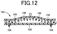
- This appropriately restrains the design surface from becoming loose or wrinkled, being lifted, etc. due to the difference in thermal expansion and improves the product quality. That is, since the engaging projections can move relatively, an effect due to the difference in thermal expansion is reduced (lessened) as one of the first and second members moves to a peripheral portion of normal temperature etc. where the difference in thermal expansion is smaller. Accordingly, local loosening or local lifting of the upholstery material 102 as in the case where the engaging projections 104 are placed at the fixed positions as in FIG. 12 can be inhibited.
- the first aspect of the invention is directed to the case where the bridge having the slit in the middle so as to be separated into a plurality of parts is used as the stopper portion.
- the annular engaging projection is inserted through the insertion hole by elastically deforming the bridge and expanding the slit, and is thus retained in the insertion hole by the bridge and is allowed to move relatively in the longitudinal direction of the bridge.
- the second aspect of the invention is directed to the case where the hook portion that projects into the insertion hole is used as the stopper portion.
- the annular engaging projection is inserted through the insertion hole and is held by the hook portion, whereby the engaging projection is retained in the insertion hole, and the engaging projection is allowed to move relatively in the longitudinal direction of the hook portion.
- the stopper portion recited in the third and fourth aspects of the invention has a tilt, so that the engaging projection is guided further into the insertion hole as a result of the relative movement that occurs due to the difference in thermal expansion in the direction in which the design surface becomes loose. Accordingly, the second member more closely contacts the first member. This more appropriately restrains the design surface from becoming loose or wrinkled, being lifted, etc.
- the present invention is applied to vehicle interior parts such as a door trim, a luggage side trim, and an instrument panel, and ornaments etc. that are attached to the interior parts, but is also applicable to panel parts for applications other than vehicle applications.
- first member as the base member
- relatively hard synthetic resin materials such as rigid polyvinyl chloride, polypropylene, polyethylene, and ABS are preferably used.
- first member may be made of other materials such as a metal.
- various thermoplastic resins such as plasticized polyvinyl chloride, styrene resin, olefin resin, and polyester resin are preferably used.
- the upholstery material is not limited to various resin materials, and may be a stacked material having woven fabric, nonwoven fabric, knitted fabric, etc. bonded to a resin sheet.
- a relatively hard base member may be placed on the back surface (on the opposite side from the protrusions) of the second member as necessary.
- the multiplicity of protrusions that provide the cushioning properties have, e.g., a rectangular shape as viewed in plan, but may have various shapes such as a square shape, a circular shape, an elliptical shape, or a curved shape curved in an arc.
- Each protrusion may have a sectional shape that continuously changes in the direction in which the protrusion protrudes, such as a tapered shape in which the sectional area of the protrusion decreases toward the tip end thereof, or may have an asymmetrical shape with respect to a centerline in order to facilitate bending of the protrusion in one direction. All of the multiplicity of protrusions may have the same shape.
- the multiplicity of protrusions may be a mixture of a plurality of kinds of protrusions having different shapes.
- the protrusions are not limited to pin-shaped protrusions.
- a multiplicity of elongated rib-like (flat plate-shaped) protrusions may be arranged parallel to each other or in a grid pattern.
- the design surface tends to become loose or wrinkled, be lifted, etc. due to the shape of the curved portion, and it is desirable to connect the first and second members together by the engaging projection.
- loosening, lifting, etc. of the design surface due to the difference in thermal expansion occurs not only in such a curved portion but also in a flat portion etc.
- the present invention is preferably applied not only to laminated composite parts having a curved portion so as to provide a recessed design surface, but also to laminated composite parts having various shapes, such as flat laminated composite parts that do not have such a curved portion or laminated composite parts having a curved shape so as to provide a protruded design surface.
- the engaging projection inserted through the insertion hole is engaged with the stopper portion and retained in the insertion hole by the stopper portion, and is allowed to move relatively in the direction parallel to the design surface due to the difference in thermal expansion.
- the stopper portion has the predetermined length L in the direction of the relative movement. The direction of the relative movement that occurs due to the difference in thermal expansion and the predetermined length L are determined as appropriate in advance by experiments, simulations, etc. based on the shape of the design surface, the materials and thicknesses of the first and second members, etc. so as to restrain the design surface from becoming loose or wrinkled, being lifted, etc.
- the direction in which the engaging projection is allowed to move relatively namely the direction in which the stopper portion extends, need not necessarily be exactly the same as the direction of the relative movement that occurs due to the difference in thermal expansion, and is determined so as to include a component of the direction of the relative movement. Namely, the engaging projection needs only to be relatively moved along the stopper portion due to the difference in thermal expansion so as to restrain the design surface from becoming loose or wrinkled, being lifted, etc.
- the bridge of the first aspect of the invention be formed symmetrically by a pair of projecting bridges that project toward each other like a cantilever along a straight line, with a slit in the middle (clearance).
- the bridge may be formed asymmetrically.
- the stopper portion has a tilt so that the engaging projection is guided further into the insertion hole.
- the stopper portion needs only to be provided so as to at least allow the engaging projection to move relatively due to the difference in thermal expansion.
- the stopper portion may extend substantially parallel to the design surface so that the engaging projection moves substantially parallel along the design surface.
- the tilt of the stopper portion may be provided such that only a surface on which the engaging projection is retained is tilted.
- the stopper portion itself such as the hook portion of the second aspect of the invention may be tilted.
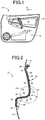
- FIG. 1 is a schematic front view of a vehicle door trim 10 to which the present invention is applicable, as viewed from the design surface side, namely from the interior of a vehicle.
- FIG. 2 is an enlarged sectional view of the vehicle door trim 10 taken along line II-II and viewed in the direction of arrows in FIG. 1 . That is, FIG. 2 is a longitudinal section of an armrest part 12 mounted in the vehicle door trim 10.
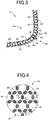
- FIG. 3 is an enlarged sectional view of a portion III in FIG. 2 .
- the armrest part 12 corresponds to the laminated composite part.
- the armrest part 12 is fitted in an opening 16 in a door trim body 14 from the back side (the right side in FIG. 2 ) of the door trim body 14, and is fixedly attached to the door trim body 14 via a plurality of attachment portions 18 provided at the peripheral edge of the armrest part 12.
- the armrest part 12 is formed by a three-dimensionally curved plate-shaped base member 20, and an upholstery material 24 placed on a front surface 22 of the base member 20 so as to be substantially parallel to the front surface 22.
- the upholstery material 24 is the second member, and is molded as a single-piece member with a relatively soft, elastically deformable synthetic resin material such as plasticized polyvinyl chloride.
- a multiplicity of fine protrusions 26 that protrude toward the front surface 22 of the base member 20 are formed integrally with a back surface 24r of the upholstery material 24, namely a surface of the upholstery material 24 on the base member 20 side, so as to spread all over the back surface 24r of the upholstery material 24. These fine protrusions 26 create space 28 between the upholstery material 24 and the front surface 22.
- An outer peripheral terminal portion 30 of the upholstery material 24 covers and is fixed to an outer peripheral edge of the base member 20 with the tip ends of the fine protrusions 26 being in close contact with the front surface 22.
- the outer peripheral terminal portion 30 is pressed against the outer peripheral edge of the base member 20 by the opening 16, and is thus kept in close contact with the outer peripheral edge.
- the outer peripheral terminal portion 30 may be fixed to the outer peripheral edge of the base member 20 by fixing means such as an adhesive.
- the base member 20 corresponds to the first member, and is molded as a single-piece member with a synthetic resin material harder than the upholstery material 24, such as polypropylene.
- the attachment portions 18 are provided integrally with the base member 20.
- the fine protrusions 26 correspond to the protrusions, and the front surface 22 of the base member 20 corresponds to the mating surface.
- Woven fabric, nonwoven fabric, etc. may be placed on the front surface of the upholstery material 24, namely the design surface on the opposite side of the upholstery material 24 from the fine protrusions 26.
- FIG. 4 is a diagram illustrating the multiplicity of fine protrusions 26 formed on the back surface 24r of the upholstery material 24, which is an enlarged plan view as viewed in the direction perpendicular to the back surface 24r.
- FIG. 5 is an enlarged longitudinal section taken along line V-V and viewed in the direction of arrows in FIG. 4 .
- FIG. 6 is an enlarged longitudinal section taken along line VI-VI and viewed in the direction of arrows in FIG. 4 .
- the multiplicity of fine protrusions 26 have the same shape, and have a longitudinal shape (in the present embodiment, a rectangular shape) as viewed in plan (in the state shown in FIG. 4 ).
- the fine protrusions 26 are arranged in a grid pattern 32 of a multiplicity of polygons of the same shape in which adjoining ones of the polygons have a common side such that the fine protrusions 26 form the sides of the polygons.
- the fine protrusions 26 have a rectangular shape with four round corners as viewed in plan and are arranged in such an attitude that the longitudinal directions of the fine protrusions 26 correspond to the sides of the polygons. As shown by long dashed double-short dashed lines in FIG.
- the grid pattern 32 is a honeycomb pattern, namely a repeated pattern of regular hexagons of a fixed size as the polygons, and the fine protrusions 26 are provided so that a single fine protrusion 26 is located on the middle part of each side of the regular hexagons.
- FIGS. 5 and 6 are sectional views specifically showing an example of the fine protrusions 26.
- the fine protrusions 26 have a gently tapered shape so that its sectional area decreases toward its tip end.
- Both a longitudinal section in FIG. 5 taken along the lateral direction perpendicular to the longitudinal direction and a longitudinal section in FIG. 6 taken along the longitudinal direction have a symmetrical shape with respect to a neutral plane perpendicular to the back surface 24r, and the peripheral edge of the tip end of each fine protrusion 26 (both ends of the tip end of the sectional shape) is rounded as viewed in these longitudinal sections.
- the dimensions and angles of each part of the fine protrusions 26 are determined as appropriate in view of the material of the upholstery material 24 etc. so that a predetermined feel (soft feel etc.) is provided.
- the fine protrusions 26 are merely in contact with the front surface 22 of the base member 20. Accordingly, in a curved portion that is curved two-dimensionally or three-dimensionally so as to provide a recessed design surface, such as an inwardly curved portion 12a in FIG. 2 , there is a risk that a gap may appear between the front surface 22 of the base member 20 and the fine protrusions 26, and the upholstery material 24 may therefore become loose or wrinkled or be lifted and abnormal noise may be generated due to a position shift associated with such a loose or lifted upholstery material 24. This may impair the product quality.
- the portion III in FIG. 2 namely the portion shown in FIG. 3 , is the inwardly curved portion 12a.
- connection mechanisms 40 are shown as a reference example.
- the connection mechanisms 40 will be specifically described with reference to FIGS. 3 and 7A to 7D .
- the connection mechanism 40 includes engaging projections 42 formed so as to stand on the back surface 24r of the upholstery material 24, and an insertion hole 44 formed in the base member 20.
- Each engaging projection 42 projects to a larger extent than the fine protrusions 26 and has a retaining claw 42p at its tip end.
- the tip ends of the engaging projections 42 are relatively inserted through the insertion hole 44 so as to project beyond a back surface of the base member 20.
- the retaining claws 42p are caught by the peripheral edge of the opening of the insertion hole 44, so that the engaging projections 42 are retained in the insertion hole 44.
- the upholstery material 24 is thus connected to the base member 20 and is prevented from being lifted etc.
- the engaging projections 42 are molded integrally with the upholstery material 24.
- the engaging projections 42 may be formed as separate members from the upholstery material 24 and may be fixedly attached to the back surface 24r of the upholstery material 24 by welding, an adhesive, etc.
- FIGS. 7A to 7D show views illustrating how to place the upholstery material 24 on the base member 20 while inserting the engaging projections 42 through the insertion hole 44 and attach the upholstery material 24 to the base member 20.
- FIG. 7A is a perspective view of the engaging projections 42 on the back surface 24r of the upholstery material 24
- FIG. 7B is a perspective view of the insertion hole 44 formed in the base member 20
- FIG. 7C is a perspective view of the pair of engaging projections 42 inserted through the insertion hole 44
- FIG. 7D is a perspective view of the engaging projections 42 positioned so as to be caught by the peripheral edge of the opening of the insertion hole 44.
- the upholstery material 24 having the engaging projections 42 corresponds to the one member, and the base member 20 having the insertion hole 44 corresponds to the other member.
- the multiplicity of fine protrusions 26 formed on the back surface 24r of the upholstery material 24 are not shown in FIGS. 7A to 7D .
- the fine protrusions 26 are not shown in FIGS. 9A to 9C , 10A to 10C , and 11 .
- the insertion hole 44 has a rectangular shape sufficiently larger than a region including the pair of engaging projections 42, so that these engaging projections 42 can be inserted through the insertion hole 44 with sufficient clearance.
- a lid member 48 is formed integrally with one of the long sides of the peripheral edge of the opening of the rectangular insertion hole 44 via an integral hinge 46 such that the lid member 48 can be opened and closed. As shown in FIGS. 7B and 7C , the engaging projections 42 are inserted into the lid member 48 being opened wide and the insertion hole 44 opening wide.
- the lid member 48 has rectangular notches 50 in its two corners so that the notches correspond to the pair of engaging projections 42.
- the engaging projections 42 are positioned by the notches 50 and are held in the retained state, or the state where the retaining claws 42p are caught by the peripheral edge of the opening of the insertion hole 44 and retained in the insertion hole 44.
- those portions which catch the retaining claws 42p of the engaging projections 42 positioned by the notches 50 namely the right and left portions of the lower long side in FIG. 7D , function as stopper portions 52.
- the lid member 48 is press-fitted in the insertion hole 44 and is fixed closed.
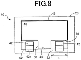
- FIG. 8 is a front view (as viewed from the back side of the base member 20) showing the state where the upholstery material 24 is attached to the base member 20 and the lid member 48 is closed so that the engaging projections 42 are caught by the stopper portions 52 of the insertion hole 44 according to the procedures shown in FIGS. 7A to 7D .
- the notches 50 have a sufficiently larger length dimension L than the engaging projections 42 so that the engaging projections 42 can move relative to the base member 20 within the range of the length dimension L. This allows the engaging projections 42 to move relative to the stopper portions 52 in the direction parallel to the design surface, namely in the direction parallel to the direction tangential to the base member 20 and the upholstery material 24, due to the difference in thermal expansion between the upholstery material 24 and the base member 20.
- the direction in which the engaging projections 42 are allowed to move relatively namely the direction in which the stopper portions 52 extend, which is the longitudinal direction of the insertion hole 44 in the reference example, is determined as appropriate in advance by experiments, simulations, etc. based on the shape of the design surface, the materials and thicknesses of the upholstery material 24 and the base member 20, etc. so as to restrain the upholstery material 24 from becoming loose or wrinkled, being lifted, etc. due to the difference in thermal expansion. That is, the longitudinal direction of the insertion hole 44 may be determined so as to include a component of the direction of the relative movement that occurs due to the difference in thermal expansion between the upholstery material 24 and the base member 20.
- the length dimension L within which the relative movement can be made is similarly determined as appropriate by experiments, simulations, etc. so as to restrain the upholstery material 24 from becoming loose or wrinkled, being lifted, etc. due to the difference in thermal expansion.
- the stopper portions 52 that are engaged with the engaging projections 42 and retain the engaging projections 42 in the insertion hole 44 have the predetermined length L, and the engaging projections 42 are allowed to move relatively within the range of the length dimension L in the direction parallel to the design surface due to the difference in thermal expansion between the upholstery material 24 and the base member 20.
- This appropriately restrains the upholstery material 24 from becoming loose or wrinkled, being lifted, etc. due to the difference in thermal expansion and improves the product quality. That is, since the engaging projections 42 can move relative to the base member 20, an effect due to the difference in thermal expansion is reduced (lessened) as the engaging projections 42 move to a peripheral portion of normal temperature etc. where the difference in thermal expansion is smaller. Accordingly, local loosening or local lifting of the upholstery material 102 as in the case where the engaging projections 104 are placed at the fixed positions as in FIG. 12 can be inhibited.
- the lid member 48 is attached to the insertion hole 44 so as to allow the engaging projections 42 to move relatively and so as to maintain the retained state where the retaining claws 42p are caught by the stopper portions 52. Accordingly, the insertion hole 44 sufficiently larger than the engaging projections 42 can be used, and the engaging projections 42 can be easily and quickly inserted into the insertion hole 44 when the upholstery material 24 is placed on the base member 20 and attached thereto. Workability in attaching the upholstery material 24 to the base member 20 can thus be improved.
- FIGS. 9A to 9C are the embodiment of the first aspect of the invention and show perspective views showing the states before and after the upholstery material 24 is placed on the base member 20 and attached thereto.
- FIG. 9A is a perspective view of an insertion hole 62 formed in the base member 20
- FIG. 9B is a perspective view of an engaging projection 64 on the back surface 24r of the upholstery material 24
- FIG. 9C is a perspective view of the upholstery material 24 and the base member 20 connected together with the engaging projection 64 inserted through the insertion hole 62.
- the insertion hole 62 has a rectangular shape, and a bridge 66 is formed so as to connect the pair of parallel long sides of the insertion hole 62 together.
- the bridge 66 functions as a stopper portion and has symmetrically a pair of projecting bridges 68 that project toward each other like a cantilever along a straight line parallel to the short sides of the insertion hole 62.
- the engaging projection 64 has an annular shape, namely a semicircular arc shape or an inverted U-shape, and has a pair of holding portions 72 projecting from its tip end portion.
- the engaging projection 64 is formed as a separate member from the upholstery material 24 and is fixedly attached to the back surface 24r of the upholstery material 24 by welding, an adhesive, etc.
- the engaging projection 64 is inserted through the insertion hole 62 by moving the engaging projection 64 toward the insertion hole 62 such that the pair of holding portions 72 are located on both sides of the bridge 66 and holding and pulling the holding portions 72 such that the engaging projection 64 elastically deforms the pair of projecting bridges 68 and expands the clearance 70. As shown in FIG.
- the bridge 66 thus extends through the opening of the annular engaging projection 64, so that the engaging projection 64 is retained in the insertion hole 62 by the bridge 66 and is allowed to move relatively within the range of the longitudinal length dimension L of the bridge 66.
- the clearance 70 is smaller than the thickness dimension of the engaging projection 64, and there is no risk that the engaging projection 64 may come off through the clearance 70.
- the longitudinal direction of the bridge 66 namely the short sides of the insertion hole 62, are determined so as to include a component of the direction of the relative movement that occurs due to the difference in thermal expansion between the upholstery material 24 and the base member 20.
- the annular engaging projection 64 is inserted through the insertion hole 62 by elastically deforming the bridge 66 and expanding the clearance 70, and is thus retained in the insertion hole 62 by the bridge 66.
- the bridge 66 has the predetermined length L and the engaging projection 64 is allowed to move relatively within the range of the length dimension L in the direction parallel to the design surface due to the difference in thermal expansion between the upholstery material 24 and the base member 20. As in the above reference example, this appropriately restrains the upholstery material 24 from becoming loose or wrinkled, being lifted, etc. due to the difference in thermal expansion and improves the product quality.
- FIGS. 10A to 10C are the embodiments of the second to fourth aspects of the invention and show perspective views showing the states before and after the upholstery material 24 is placed on the base member 20 and attached thereto.
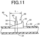
- FIG. 11 is a sectional view taken along line XI-XI and viewed in the direction of arrows in FIG. 10C.
- FIG. 10A is a perspective view of an insertion hole 82 formed in the base member 20
- FIG. 10B is a perspective view of an engaging projection 84 on the back surface 24r of the upholstery material 24, and FIG.
- FIG. 10C is a perspective view of the upholstery material 24 and the base member 20 connected together with the engaging projection 84 inserted through the insertion hole 82.
- the insertion hole 82 has a rectangular shape, and a hook portion 86 is formed on one of the long sides of the insertion hole 82 so as to project into the insertion hole 82.
- the hook portion 86 functions as a stopper portion, and extends parallel to the short sides of the insertion hole 82 like a cantilever such that clearance 88 is left between the tip end of the hook portion 86 and the other long side of the insertion hole 82.
- the engaging projection 84 has an annular shape, namely a semicircular arc shape or an inverted U-shape, and has a holding portion 90 at its tip end portion.
- the engaging projection 84 is formed as a separate member from the upholstery material 24 and is fixedly attached to the back surface 24r of the upholstery material 24 by welding, an adhesive, etc.
- the engaging projection 84 is inserted through the insertion hole 82 and is held by the hook portion 86 by moving the engaging projection 84 toward the insertion hole 82 such that the holding portion 90 is located in the clearance 88 and holding and pulling the holding portion 90. As shown in FIG.
- the hook portion 86 thus extends through the opening of the annular engaging projection 84, so that the engaging projection 84 is retained in the insertion hole 82 by the hook portion 86 and is allowed to move relatively within the range of the longitudinal length dimension L of the hook portion 86.
- the hook portion 86 has a stopper 92 formed at its tip end so as to project from the hook portion 86.
- the longitudinal direction of the hook portion 86 namely the short sides of the insertion hole 82, are determined so as to include a component of the direction of the relative movement that occurs due to the difference in thermal expansion between the upholstery material 24 and the base member 20.
- the upper surface of the hook portion 86 namely a retaining surface 94 on which the engaging projection 84 is held, is a tilted surface tilted toward the back surface of the base member 20, namely tilted to the opposite side from the upholstery material 24, as the retaining surface 94 extends to the tip end of the hook portion 86. Accordingly, as the engaging projection 84 is moved toward the tip end of the hook portion 86 as a result of the relative movement that occurs due to the difference in thermal expansion, the engaging projection 84 is guided further into the insertion hole 82 by the tilt of the retaining surface 94, so that the upholstery material 24 is moved toward the base member 20.
- the direction in which the retaining surface 94 is tilted is determined as appropriate so that the engaging projection 84 is guided further into the insertion hole 82 when the upholstery material 24 expands at high temperatures and is moved relative to the base member 20 due to the difference in thermal expansion.
- the annular engaging projection 84 is inserted through the insertion hole 82 and is held by the hook portion 86, whereby the engaging projection 84 is retained in the insertion hole 82.
- the hook portion 86 has the predetermined length L in the longitudinal direction thereof, and the engaging projection 84 is allowed to move relatively within the range of the length dimension L in the direction parallel to the design surface due to the difference in thermal expansion between the upholstery material 24 and the base member 20. As in the above reference example, this appropriately restrains the upholstery material 24 from becoming loose or wrinkled, being lifted, etc. due to the difference in thermal expansion and improves the product quality.
- the retaining surface 94 of the hook portion 86 is a tilted surface, so that the engaging projection 84 is guided further into the insertion hole 82 as a result of the relative movement that occurs due to the difference in thermal expansion in the direction in which the design surface becomes loose, namely due to the difference in thermal expansions at high temperatures. Accordingly, the upholstery material 24 is moved toward the base member 20 and closely contacts the base member 20. This more appropriately restrains the design surface from becoming loose or wrinkled, being lifted, etc.
- Armrest part (Laminated composite part) 20: Base member (First member, the other of the first and second members) 22: Front surface (Mating surface) 24: Upholstery material (Second member, one of the first and second members) 26: Fine protrusions (Protrusions) 28: Space 64, 84: Engaging projection 62, 82: Insertion hole 66: Bridge (Stopper portion) 70: Clearance (Slit) 86: Hook portion (Stopper portion) 94: Retaining surface (Tilted surface) L: Length dimension
Landscapes
- Engineering & Computer Science (AREA)
- Mechanical Engineering (AREA)
- Vehicle Interior And Exterior Ornaments, Soundproofing, And Insulation (AREA)
- Connection Of Plates (AREA)
Claims (4)
- Mehrschichtige Verbundwerkstoffkomponente (12), die ein erstes Bauteil (20) mit einer vorbestimmten Anlagefläche (22) und ein zweites Bauteil (24) umfasst, das aus einem elastisch verformbaren Harzwerkstoff hergestellt ist, das einen im Wesentlichen zu der Anlagefläche parallelen Plattenabschnitt hat und eine Vielzahl von Vorsprüngen (26) hat, die einstückig mit diesem ausgebildet sind, um in Richtung der Anlagefläche vorzustehen, sodass ein Raum (28) zwischen dem Plattenabschnitt und der Anlagefläche erzeugt wird, und das auf dem ersten Bauteil derart platziert ist, dass die Vorsprünge die Anlagefläche kontaktieren, das Dämpfungseigenschaften hat, wenn Endspitzen der Vorsprünge gegen die Anlagefläche gedrückt werden und elastisch verformt werden, und in dem eines (24) von dem ersten und zweiten Bauteil, das an einer Gestaltungsflächenseite gelegen ist, einen Eingriffsvorsprung (64; 84) hat, der in einem größeren Ausmaß als die Vorsprünge vorsteht, und wobei der Eingriffsabschnitt durch ein Einsatzloch (62; 82), das in dem anderen (20) von dem ersten und zweiten Bauteil ausgebildet ist, eingesetzt ist und in dem Einsatzloch gehalten wird, wodurch das erste und zweite Bauteil miteinander verbunden sind, dadurch gekennzeichnet, dass
das Einsatzloch mit einem Stopperabschnitt (66; 86) versehen ist, der mit dem Eingriffsabschnitt im Eingriff ist, um den Eingriffsabschnitt in dem Einsatzloch zu halten,
der Stopperabschnitt, um zu ermöglichen, dass sich der Eingriffsabschnitt bezüglich des Stopperabschnittes in einer Richtung parallel zu der Gestaltungsfläche aufgrund eines Unterschieds in der Wärmeausdehnung zwischen dem ersten und zweiten Bauteil bewegt, eine vorbestimmte Länge (L) in einer Richtung der Relativbewegung hat, die aufgrund der unterschiedlichen Wärmeausdehnung stattfindet,
der Stopperabschnitt (66) eine Brücke ist, die sich über das Einsatzloch (62) erstreckt und einen Schlitz (70) in einer Mitte hat, um in eine Vielzahl von Teilen getrennt zu sein, und
der Eingriffsabschnitt (64) eine ringförmige Form hat und durch das Einsatzloch derart eingesetzt ist, dass der Eingriffsvorsprung die Brücke elastisch verformt und den Schlitz elastisch ausweitet, und sich die Brücke somit durch eine Öffnung der ringförmigen Form erstreckt, sodass der Eingriffsabschnitt in dem Einsatzloch durch die Brücke gehalten wird und sich in einer Längsrichtung der Brücke relativ bewegen kann. - Mehrschichtige Verbundwerkstoffkomponente (12), die ein erstes Bauteil (20) mit einer vorbestimmten Anlagefläche (22) und ein zweites Bauteil (24) umfasst, das aus einem elastisch verformbaren Harzwerkstoff hergestellt ist, das einen im Wesentlichen zu der Anlagefläche parallelen Plattenabschnitt hat und eine Vielzahl von Vorsprüngen (26) hat, die einstückig mit diesem ausgebildet sind, um in Richtung der Anlagefläche vorzustehen, sodass ein Raum (28) zwischen dem Plattenabschnitt und der Anlagefläche erzeugt wird, und das auf dem ersten Bauteil derart platziert ist, dass die Vorsprünge die Anlagefläche kontaktieren, das Dämpfungseigenschaften hat, wenn Endspitzen der Vorsprünge gegen die Anlagefläche gedrückt werden und elastisch verformt werden, und in dem eines (24) von dem ersten und zweiten Bauteil, das an einer Gestaltungsflächenseite gelegen ist, einen Eingriffsvorsprung (64; 84) hat, der in einem größeren Ausmaß als die Vorsprünge vorsteht, und wobei der Eingriffsabschnitt durch ein Einsatzloch (62; 82), das in dem anderen (20) von dem ersten und zweiten Bauteil ausgebildet ist, eingesetzt ist und in dem Einsatzloch gehalten wird, wodurch das erste und zweite Bauteil miteinander verbunden sind, dadurch gekennzeichnet, dass
das Einsatzloch mit einem Stopperabschnitt (66; 86) versehen ist, der mit dem Eingriffsabschnitt im Eingriff ist, um den Eingriffsabschnitt in dem Einsatzloch zu halten,
der Stopperabschnitt, um zu ermöglichen, dass sich der Eingriffsabschnitt bezüglich des Stopperabschnittes in einer Richtung parallel zu der Gestaltungsfläche aufgrund eines Unterschieds in der Wärmeausdehnung zwischen dem ersten und zweiten Bauteil bewegt, eine vorbestimmte Länge (L) in einer Richtung der Relativbewegung hat, die aufgrund der unterschiedlichen Wärmeausdehnung stattfindet,
der Stopperabschnitt ein Hakenabschnitt ist, der in das Einsatzloch wie ein Ausleger vorsteht, und
der Eingriffsabschnitt eine ringförmige Form hat, wobei der Eingriffsabschnitt durch das Einsatzloch eingesetzt ist und durch den Hakenabschnitt gehalten wird, sodass der Eingriffsabschnitt in dem Einsatzloch gehalten wird und sich der Eingriffsabschnitt in einer Längsrichtung des Hakenabschnitts relativ bewegen kann. - Mehrschichtige Verbundwerkstoffkomponente gemäß Anspruch 1 oder 2, wobei
der Stopperabschnitt (86) eine Neigung hat, sodass der Eingriffsabschnitt (84) als Folge der Relativbewegung, die aufgrund der unterschiedlichen Wärmeausdehnung stattfindet, weiter in das Einsatzloch (82) in einer Richtung geführt wird, in der die Gestaltungsfläche locker wird. - Mehrschichtige Verbundwerkstoffkomponente (12), die ein erstes Bauteil (20) mit einer vorbestimmten Anlagefläche (22) und ein zweites Bauteil (24) umfasst, das aus einem elastisch verformbaren Harzwerkstoff hergestellt ist, das einen im Wesentlichen zu der Anlagefläche parallelen Plattenabschnitt hat und eine Vielzahl von Vorsprüngen (26) hat, die einstückig mit diesem ausgebildet sind, um in Richtung der Anlagefläche vorzustehen, sodass ein Raum (28) zwischen dem Plattenabschnitt und der Anlagefläche erzeugt wird, und das auf dem ersten Bauteil derart platziert ist, dass die Vorsprünge die Anlagefläche kontaktieren, das Dämpfungseigenschaften hat, wenn Endspitzen der Vorsprünge gegen die Anlagefläche gedrückt werden und elastisch verformt werden, und in dem eines (24) von dem ersten und zweiten Bauteil, das an einer Gestaltungsflächenseite gelegen ist, einen Eingriffsvorsprung (64; 84) hat, der in einem größeren Ausmaß als die Vorsprünge vorsteht, und wobei der Eingriffsabschnitt durch ein Einsatzloch (62; 82), das in dem anderen (20) von dem ersten und zweiten Bauteil ausgebildet ist, eingesetzt ist und in dem Einsatzloch gehalten wird, wodurch das erste und zweite Bauteil miteinander verbunden sind, dadurch gekennzeichnet, dass
das Einsatzloch mit einem Stopperabschnitt (66; 86) versehen ist, der mit dem Eingriffsabschnitt im Eingriff ist, um den Eingriffsabschnitt in dem Einsatzloch zu halten,
der Stopperabschnitt, um zu ermöglichen, dass sich der Eingriffsabschnitt bezüglich des Stopperabschnittes in einer Richtung parallel zu der Gestaltungsfläche aufgrund eines Unterschieds in der Wärmeausdehnung zwischen dem ersten und zweiten Bauteil bewegt, eine vorbestimmte Länge (L) in einer Richtung der Relativbewegung hat, die aufgrund der unterschiedlichen Wärmeausdehnung stattfindet, und
der Stopperabschnitt (86) eine Neigung hat, sodass der Eingriffsabschnitt (84) als Folge der Relativbewegung, die aufgrund der unterschiedlichen Wärmeausdehnung stattfindet, weiter in das Einsatzloch (82) in einer Richtung geführt wird, in der die Gestaltungsfläche locker wird.
Applications Claiming Priority (2)
| Application Number | Priority Date | Filing Date | Title |
|---|---|---|---|
| JP2014076565A JP6111217B2 (ja) | 2014-04-02 | 2014-04-02 | 重ね合わせ複合部品 |
| PCT/JP2014/077760 WO2015151322A1 (ja) | 2014-04-02 | 2014-10-18 | 重ね合わせ複合部品 |
Publications (3)
| Publication Number | Publication Date |
|---|---|
| EP3127751A1 EP3127751A1 (de) | 2017-02-08 |
| EP3127751A4 EP3127751A4 (de) | 2017-11-01 |
| EP3127751B1 true EP3127751B1 (de) | 2018-12-12 |
Family
ID=54239680
Family Applications (1)
| Application Number | Title | Priority Date | Filing Date |
|---|---|---|---|
| EP14888205.3A Not-in-force EP3127751B1 (de) | 2014-04-02 | 2014-10-18 | Geschichtete verbundstoffkomponente |
Country Status (5)
| Country | Link |
|---|---|
| US (1) | US10207655B2 (de) |
| EP (1) | EP3127751B1 (de) |
| JP (1) | JP6111217B2 (de) |
| CN (1) | CN106163878B (de) |
| WO (1) | WO2015151322A1 (de) |
Families Citing this family (10)
| Publication number | Priority date | Publication date | Assignee | Title |
|---|---|---|---|---|
| JP6131233B2 (ja) * | 2014-10-24 | 2017-05-17 | 豊田鉄工株式会社 | 重ね合わせ複合内装部品 |
| JP2016107840A (ja) | 2014-12-05 | 2016-06-20 | 豊田鉄工株式会社 | 車両用内装パネル |
| US10293762B2 (en) | 2014-11-26 | 2019-05-21 | Toyota Iron Works Co., Ltd. | Vehicular interior component, vehicular interior panel, and vehicular composite interior component |
| JP6525201B2 (ja) * | 2015-09-18 | 2019-06-05 | トヨタ紡織株式会社 | ドアトリム及び車両用ドア |
| JP6901676B2 (ja) * | 2017-02-16 | 2021-07-14 | テイ・エス テック株式会社 | 乗物用シート |
| US10933819B2 (en) * | 2018-04-20 | 2021-03-02 | Moriroku Technology Company, Ltd. | Member assembly |
| JP7146577B2 (ja) * | 2018-11-02 | 2022-10-04 | 株式会社三洋物産 | 遊技機 |
| JP6922004B2 (ja) * | 2020-01-07 | 2021-08-18 | 豊田鉄工株式会社 | 表層付き部品の製造装置及び表層付き部品の製造方法 |
| KR20230093273A (ko) * | 2020-10-19 | 2023-06-27 | 테트로 엘티디. | 서스펜션 품질을 갖는 하이브리드 구조체 |
| US20250269801A1 (en) * | 2024-02-26 | 2025-08-28 | GM Global Technology Operations LLC | Vechicle storage compartment along a top surface of a door interior panel |
Family Cites Families (28)
| Publication number | Priority date | Publication date | Assignee | Title |
|---|---|---|---|---|
| JPS59220432A (ja) * | 1983-05-28 | 1984-12-11 | Kasai Kogyo Co Ltd | 自動車用内装材における装飾用モ−ルの取付構造 |
| JPH037228Y2 (de) * | 1985-05-29 | 1991-02-22 | ||
| JP2707011B2 (ja) * | 1991-11-26 | 1998-01-28 | 株式会社国盛化学 | 板状体の固着方法 |
| JP3129608B2 (ja) * | 1994-08-23 | 2001-01-31 | 河西工業株式会社 | 内装部品における緩衝構造 |
| US6179298B1 (en) * | 1998-11-02 | 2001-01-30 | Dana Corporation | Snap-lock attachment element for laminating multiple gasket layers and method of using same |
| DE60019472T2 (de) * | 1999-06-02 | 2006-02-23 | Toyoda Gosei Co., Ltd., Nishikasugai | Kopfschützende Airbagvorrichtung |
| DE20016889U1 (de) * | 2000-09-29 | 2000-12-21 | Schwarz Verbindungs-Systeme GmbH, 75382 Althengstett | In X/Y-Richtung justierbare Platten-Einheit für lösbar durch Feder-Clips anzubringende Wandverkleidungselemente o.dgl. |
| FR2821130B1 (fr) * | 2001-02-16 | 2003-12-12 | Peugeot Citroen Automobiles Sa | Agrafe de fixation d'un element de carrosserie sur la structure d'un vehicule automobile |
| US6952863B2 (en) * | 2002-09-13 | 2005-10-11 | Southco, Inc. | Tether clip system |
| JP4211713B2 (ja) * | 2003-09-05 | 2009-01-21 | トヨタ紡織株式会社 | 結合構造 |
| WO2005039857A1 (en) * | 2003-10-16 | 2005-05-06 | Johnson Controls Technology Company | Vehicle component and method for making a vehicle component |
| US7104590B2 (en) * | 2004-07-01 | 2006-09-12 | Lear Corporation | Vehicle trim panel with integral nibbed armrest |
| US7461436B2 (en) * | 2004-10-26 | 2008-12-09 | Piolax, Inc. | Mounting structure of vehicle interior material |
| CN100368231C (zh) * | 2005-04-30 | 2008-02-13 | 全兴工业股份有限公司 | 一种汽车门板组装方法 |
| JP4713455B2 (ja) * | 2006-12-19 | 2011-06-29 | 株式会社パイオラックス | クリップ |
| FR2915539B1 (fr) * | 2007-04-26 | 2009-07-24 | Attax Sarl | Systeme de fixation de deux pieces l'une sur l'autre |
| US8793845B2 (en) * | 2008-10-10 | 2014-08-05 | Newfrey Llc | Fastener and fastener assembly |
| US8567152B2 (en) * | 2009-01-26 | 2013-10-29 | Toyoda Iron Works Co., Ltd. | Cushion material fastening structure for interior trim part |
| CN201484319U (zh) * | 2009-06-15 | 2010-05-26 | 湖南长丰汽车内装饰有限公司 | 汽车顶篷内饰板材 |
| JP5620922B2 (ja) * | 2009-11-30 | 2014-11-05 | トヨタ車体株式会社 | クリップ |
| JP5451366B2 (ja) * | 2009-12-24 | 2014-03-26 | 株式会社ニフコ | クリップ |
| JP5684018B2 (ja) * | 2011-03-23 | 2015-03-11 | トヨタ紡織株式会社 | 車両用内装材 |
| US8859074B2 (en) * | 2012-04-23 | 2014-10-14 | Global Ip Holdings, Llc | Sandwich-type, generally planar, structural member having an attachment feature and assembly utilizing same |
| JP5764522B2 (ja) * | 2012-04-26 | 2015-08-19 | 本田技研工業株式会社 | クリップ |
| JP5864391B2 (ja) * | 2012-09-28 | 2016-02-17 | 株式会社ニフコ | クリップ |
| JP5962448B2 (ja) * | 2012-11-12 | 2016-08-03 | 豊田合成株式会社 | 収納ボックス |
| JP5767200B2 (ja) * | 2012-11-27 | 2015-08-19 | 豊田鉄工株式会社 | 重ね合わせ複合部品 |
| JP6145338B2 (ja) * | 2013-07-02 | 2017-06-07 | 矢崎総業株式会社 | 組付け部材の組付け構造 |
-
2014
- 2014-04-02 JP JP2014076565A patent/JP6111217B2/ja not_active Expired - Fee Related
- 2014-10-18 CN CN201480077732.9A patent/CN106163878B/zh not_active Expired - Fee Related
- 2014-10-18 EP EP14888205.3A patent/EP3127751B1/de not_active Not-in-force
- 2014-10-18 US US15/301,048 patent/US10207655B2/en not_active Expired - Fee Related
- 2014-10-18 WO PCT/JP2014/077760 patent/WO2015151322A1/ja not_active Ceased
Non-Patent Citations (1)
| Title |
|---|
| None * |
Also Published As
| Publication number | Publication date |
|---|---|
| JP2015196485A (ja) | 2015-11-09 |
| JP6111217B2 (ja) | 2017-04-05 |
| WO2015151322A1 (ja) | 2015-10-08 |
| US10207655B2 (en) | 2019-02-19 |
| CN106163878A (zh) | 2016-11-23 |
| EP3127751A1 (de) | 2017-02-08 |
| US20170021779A1 (en) | 2017-01-26 |
| CN106163878B (zh) | 2018-08-28 |
| EP3127751A4 (de) | 2017-11-01 |
Similar Documents
| Publication | Publication Date | Title |
|---|---|---|
| US10207655B2 (en) | Layered composite component | |
| US9488202B2 (en) | Clip | |
| US10448743B2 (en) | Crip and cord | |
| US9193286B2 (en) | Vehicle seat | |
| JP6346119B2 (ja) | 表皮係止用クリップ | |
| JP2013113419A (ja) | テザークリップおよびそれを備えたガーニッシュ取付装置 | |
| CN101811480A (zh) | 用于内饰部件的衬垫材料固定结构 | |
| JP5210670B2 (ja) | 係合構造及びこれを備えた自動車用内装部材 | |
| JP7280105B2 (ja) | 車両用シート | |
| JP2014238109A (ja) | クリップおよびカーテンエアバッグ取付構造 | |
| JP2016067082A (ja) | クリップ | |
| JPWO2011074055A1 (ja) | スライドファスナー | |
| JP2013004376A (ja) | コネクタ | |
| JP2013133876A (ja) | 部材連結構造 | |
| JP7161705B2 (ja) | 車両のガーニッシュ | |
| JP6623742B2 (ja) | クリップおよびピラーガーニッシュ取付構造 | |
| JP6680708B2 (ja) | 車両用内装部品 | |
| JP2008248966A (ja) | 固定具 | |
| JP4712782B2 (ja) | クリップによる取付構造 | |
| JP7226606B2 (ja) | 係合構造 | |
| JP4928235B2 (ja) | 車両のカーテンエアバッグ用クリップとピラーガーニッシュとの取付構造、及びカーテンエアバッグ用クリップ | |
| JP4786603B2 (ja) | クリップによる取付構造 | |
| WO2017033716A1 (ja) | クランプ及びクランプ付電線 | |
| JP4857229B2 (ja) | 支持ホルダの取付構造 | |
| JP6839798B2 (ja) | 車両用内装パネルの組付構造 |
Legal Events
| Date | Code | Title | Description |
|---|---|---|---|
| STAA | Information on the status of an ep patent application or granted ep patent |
Free format text: STATUS: THE INTERNATIONAL PUBLICATION HAS BEEN MADE |
|
| PUAI | Public reference made under article 153(3) epc to a published international application that has entered the european phase |
Free format text: ORIGINAL CODE: 0009012 |
|
| STAA | Information on the status of an ep patent application or granted ep patent |
Free format text: STATUS: REQUEST FOR EXAMINATION WAS MADE |
|
| 17P | Request for examination filed |
Effective date: 20161011 |
|
| AK | Designated contracting states |
Kind code of ref document: A1 Designated state(s): AL AT BE BG CH CY CZ DE DK EE ES FI FR GB GR HR HU IE IS IT LI LT LU LV MC MK MT NL NO PL PT RO RS SE SI SK SM TR |
|
| AX | Request for extension of the european patent |
Extension state: BA ME |
|
| DAX | Request for extension of the european patent (deleted) | ||
| A4 | Supplementary search report drawn up and despatched |
Effective date: 20171005 |
|
| RIC1 | Information provided on ipc code assigned before grant |
Ipc: B68G 7/05 20060101ALI20170928BHEP Ipc: B32B 27/08 20060101ALI20170928BHEP Ipc: B60R 13/02 20060101AFI20170928BHEP Ipc: B32B 3/06 20060101ALI20170928BHEP Ipc: B32B 3/30 20060101ALI20170928BHEP Ipc: B32B 3/26 20060101ALI20170928BHEP |
|
| GRAP | Despatch of communication of intention to grant a patent |
Free format text: ORIGINAL CODE: EPIDOSNIGR1 |
|
| STAA | Information on the status of an ep patent application or granted ep patent |
Free format text: STATUS: GRANT OF PATENT IS INTENDED |
|
| INTG | Intention to grant announced |
Effective date: 20180622 |
|
| RIN1 | Information on inventor provided before grant (corrected) |
Inventor name: SAKAI, HIDEAKI Inventor name: YOSHIDA, KENICHI Inventor name: MIYASHITA, OSAMU |
|
| GRAS | Grant fee paid |
Free format text: ORIGINAL CODE: EPIDOSNIGR3 |
|
| GRAA | (expected) grant |
Free format text: ORIGINAL CODE: 0009210 |
|
| STAA | Information on the status of an ep patent application or granted ep patent |
Free format text: STATUS: THE PATENT HAS BEEN GRANTED |
|
| AK | Designated contracting states |
Kind code of ref document: B1 Designated state(s): AL AT BE BG CH CY CZ DE DK EE ES FI FR GB GR HR HU IE IS IT LI LT LU LV MC MK MT NL NO PL PT RO RS SE SI SK SM TR |
|
| REG | Reference to a national code |
Ref country code: GB Ref legal event code: FG4D |
|
| REG | Reference to a national code |
Ref country code: CH Ref legal event code: EP |
|
| REG | Reference to a national code |
Ref country code: AT Ref legal event code: REF Ref document number: 1075512 Country of ref document: AT Kind code of ref document: T Effective date: 20181215 |
|
| REG | Reference to a national code |
Ref country code: DE Ref legal event code: R096 Ref document number: 602014038027 Country of ref document: DE |
|
| REG | Reference to a national code |
Ref country code: IE Ref legal event code: FG4D |
|
| REG | Reference to a national code |
Ref country code: NL Ref legal event code: MP Effective date: 20181212 |
|
| REG | Reference to a national code |
Ref country code: LT Ref legal event code: MG4D |
|
| PG25 | Lapsed in a contracting state [announced via postgrant information from national office to epo] |
Ref country code: ES Free format text: LAPSE BECAUSE OF FAILURE TO SUBMIT A TRANSLATION OF THE DESCRIPTION OR TO PAY THE FEE WITHIN THE PRESCRIBED TIME-LIMIT Effective date: 20181212 Ref country code: NO Free format text: LAPSE BECAUSE OF FAILURE TO SUBMIT A TRANSLATION OF THE DESCRIPTION OR TO PAY THE FEE WITHIN THE PRESCRIBED TIME-LIMIT Effective date: 20190312 Ref country code: HR Free format text: LAPSE BECAUSE OF FAILURE TO SUBMIT A TRANSLATION OF THE DESCRIPTION OR TO PAY THE FEE WITHIN THE PRESCRIBED TIME-LIMIT Effective date: 20181212 Ref country code: LT Free format text: LAPSE BECAUSE OF FAILURE TO SUBMIT A TRANSLATION OF THE DESCRIPTION OR TO PAY THE FEE WITHIN THE PRESCRIBED TIME-LIMIT Effective date: 20181212 Ref country code: BG Free format text: LAPSE BECAUSE OF FAILURE TO SUBMIT A TRANSLATION OF THE DESCRIPTION OR TO PAY THE FEE WITHIN THE PRESCRIBED TIME-LIMIT Effective date: 20190312 Ref country code: FI Free format text: LAPSE BECAUSE OF FAILURE TO SUBMIT A TRANSLATION OF THE DESCRIPTION OR TO PAY THE FEE WITHIN THE PRESCRIBED TIME-LIMIT Effective date: 20181212 Ref country code: LV Free format text: LAPSE BECAUSE OF FAILURE TO SUBMIT A TRANSLATION OF THE DESCRIPTION OR TO PAY THE FEE WITHIN THE PRESCRIBED TIME-LIMIT Effective date: 20181212 |
|
| REG | Reference to a national code |
Ref country code: AT Ref legal event code: MK05 Ref document number: 1075512 Country of ref document: AT Kind code of ref document: T Effective date: 20181212 |
|
| PG25 | Lapsed in a contracting state [announced via postgrant information from national office to epo] |
Ref country code: RS Free format text: LAPSE BECAUSE OF FAILURE TO SUBMIT A TRANSLATION OF THE DESCRIPTION OR TO PAY THE FEE WITHIN THE PRESCRIBED TIME-LIMIT Effective date: 20181212 Ref country code: SE Free format text: LAPSE BECAUSE OF FAILURE TO SUBMIT A TRANSLATION OF THE DESCRIPTION OR TO PAY THE FEE WITHIN THE PRESCRIBED TIME-LIMIT Effective date: 20181212 Ref country code: AL Free format text: LAPSE BECAUSE OF FAILURE TO SUBMIT A TRANSLATION OF THE DESCRIPTION OR TO PAY THE FEE WITHIN THE PRESCRIBED TIME-LIMIT Effective date: 20181212 Ref country code: GR Free format text: LAPSE BECAUSE OF FAILURE TO SUBMIT A TRANSLATION OF THE DESCRIPTION OR TO PAY THE FEE WITHIN THE PRESCRIBED TIME-LIMIT Effective date: 20190313 |
|
| PG25 | Lapsed in a contracting state [announced via postgrant information from national office to epo] |
Ref country code: NL Free format text: LAPSE BECAUSE OF FAILURE TO SUBMIT A TRANSLATION OF THE DESCRIPTION OR TO PAY THE FEE WITHIN THE PRESCRIBED TIME-LIMIT Effective date: 20181212 |
|
| PG25 | Lapsed in a contracting state [announced via postgrant information from national office to epo] |
Ref country code: PT Free format text: LAPSE BECAUSE OF FAILURE TO SUBMIT A TRANSLATION OF THE DESCRIPTION OR TO PAY THE FEE WITHIN THE PRESCRIBED TIME-LIMIT Effective date: 20190412 Ref country code: IT Free format text: LAPSE BECAUSE OF FAILURE TO SUBMIT A TRANSLATION OF THE DESCRIPTION OR TO PAY THE FEE WITHIN THE PRESCRIBED TIME-LIMIT Effective date: 20181212 Ref country code: PL Free format text: LAPSE BECAUSE OF FAILURE TO SUBMIT A TRANSLATION OF THE DESCRIPTION OR TO PAY THE FEE WITHIN THE PRESCRIBED TIME-LIMIT Effective date: 20181212 Ref country code: CZ Free format text: LAPSE BECAUSE OF FAILURE TO SUBMIT A TRANSLATION OF THE DESCRIPTION OR TO PAY THE FEE WITHIN THE PRESCRIBED TIME-LIMIT Effective date: 20181212 |
|
| PG25 | Lapsed in a contracting state [announced via postgrant information from national office to epo] |
Ref country code: EE Free format text: LAPSE BECAUSE OF FAILURE TO SUBMIT A TRANSLATION OF THE DESCRIPTION OR TO PAY THE FEE WITHIN THE PRESCRIBED TIME-LIMIT Effective date: 20181212 Ref country code: SM Free format text: LAPSE BECAUSE OF FAILURE TO SUBMIT A TRANSLATION OF THE DESCRIPTION OR TO PAY THE FEE WITHIN THE PRESCRIBED TIME-LIMIT Effective date: 20181212 Ref country code: RO Free format text: LAPSE BECAUSE OF FAILURE TO SUBMIT A TRANSLATION OF THE DESCRIPTION OR TO PAY THE FEE WITHIN THE PRESCRIBED TIME-LIMIT Effective date: 20181212 Ref country code: IS Free format text: LAPSE BECAUSE OF FAILURE TO SUBMIT A TRANSLATION OF THE DESCRIPTION OR TO PAY THE FEE WITHIN THE PRESCRIBED TIME-LIMIT Effective date: 20190412 Ref country code: SK Free format text: LAPSE BECAUSE OF FAILURE TO SUBMIT A TRANSLATION OF THE DESCRIPTION OR TO PAY THE FEE WITHIN THE PRESCRIBED TIME-LIMIT Effective date: 20181212 |
|
| REG | Reference to a national code |
Ref country code: DE Ref legal event code: R097 Ref document number: 602014038027 Country of ref document: DE |
|
| PLBE | No opposition filed within time limit |
Free format text: ORIGINAL CODE: 0009261 |
|
| STAA | Information on the status of an ep patent application or granted ep patent |
Free format text: STATUS: NO OPPOSITION FILED WITHIN TIME LIMIT |
|
| PG25 | Lapsed in a contracting state [announced via postgrant information from national office to epo] |
Ref country code: DK Free format text: LAPSE BECAUSE OF FAILURE TO SUBMIT A TRANSLATION OF THE DESCRIPTION OR TO PAY THE FEE WITHIN THE PRESCRIBED TIME-LIMIT Effective date: 20181212 Ref country code: AT Free format text: LAPSE BECAUSE OF FAILURE TO SUBMIT A TRANSLATION OF THE DESCRIPTION OR TO PAY THE FEE WITHIN THE PRESCRIBED TIME-LIMIT Effective date: 20181212 Ref country code: SI Free format text: LAPSE BECAUSE OF FAILURE TO SUBMIT A TRANSLATION OF THE DESCRIPTION OR TO PAY THE FEE WITHIN THE PRESCRIBED TIME-LIMIT Effective date: 20181212 |
|
| 26N | No opposition filed |
Effective date: 20190913 |
|
| PG25 | Lapsed in a contracting state [announced via postgrant information from national office to epo] |
Ref country code: TR Free format text: LAPSE BECAUSE OF FAILURE TO SUBMIT A TRANSLATION OF THE DESCRIPTION OR TO PAY THE FEE WITHIN THE PRESCRIBED TIME-LIMIT Effective date: 20181212 |
|
| PG25 | Lapsed in a contracting state [announced via postgrant information from national office to epo] |
Ref country code: MC Free format text: LAPSE BECAUSE OF FAILURE TO SUBMIT A TRANSLATION OF THE DESCRIPTION OR TO PAY THE FEE WITHIN THE PRESCRIBED TIME-LIMIT Effective date: 20181212 |
|
| REG | Reference to a national code |
Ref country code: CH Ref legal event code: PL |
|
| PG25 | Lapsed in a contracting state [announced via postgrant information from national office to epo] |
Ref country code: LU Free format text: LAPSE BECAUSE OF NON-PAYMENT OF DUE FEES Effective date: 20191018 Ref country code: CH Free format text: LAPSE BECAUSE OF NON-PAYMENT OF DUE FEES Effective date: 20191031 Ref country code: LI Free format text: LAPSE BECAUSE OF NON-PAYMENT OF DUE FEES Effective date: 20191031 |
|
| REG | Reference to a national code |
Ref country code: BE Ref legal event code: MM Effective date: 20191031 |
|
| PG25 | Lapsed in a contracting state [announced via postgrant information from national office to epo] |
Ref country code: BE Free format text: LAPSE BECAUSE OF NON-PAYMENT OF DUE FEES Effective date: 20191031 |
|
| PG25 | Lapsed in a contracting state [announced via postgrant information from national office to epo] |
Ref country code: IE Free format text: LAPSE BECAUSE OF NON-PAYMENT OF DUE FEES Effective date: 20191018 |
|
| PGFP | Annual fee paid to national office [announced via postgrant information from national office to epo] |
Ref country code: FR Payment date: 20200914 Year of fee payment: 7 |
|
| PGFP | Annual fee paid to national office [announced via postgrant information from national office to epo] |
Ref country code: GB Payment date: 20201007 Year of fee payment: 7 Ref country code: DE Payment date: 20201006 Year of fee payment: 7 |
|
| PG25 | Lapsed in a contracting state [announced via postgrant information from national office to epo] |
Ref country code: CY Free format text: LAPSE BECAUSE OF FAILURE TO SUBMIT A TRANSLATION OF THE DESCRIPTION OR TO PAY THE FEE WITHIN THE PRESCRIBED TIME-LIMIT Effective date: 20181212 |
|
| PG25 | Lapsed in a contracting state [announced via postgrant information from national office to epo] |
Ref country code: MT Free format text: LAPSE BECAUSE OF FAILURE TO SUBMIT A TRANSLATION OF THE DESCRIPTION OR TO PAY THE FEE WITHIN THE PRESCRIBED TIME-LIMIT Effective date: 20181212 Ref country code: HU Free format text: LAPSE BECAUSE OF FAILURE TO SUBMIT A TRANSLATION OF THE DESCRIPTION OR TO PAY THE FEE WITHIN THE PRESCRIBED TIME-LIMIT; INVALID AB INITIO Effective date: 20141018 |
|
| REG | Reference to a national code |
Ref country code: DE Ref legal event code: R119 Ref document number: 602014038027 Country of ref document: DE |
|
| GBPC | Gb: european patent ceased through non-payment of renewal fee |
Effective date: 20211018 |
|
| PG25 | Lapsed in a contracting state [announced via postgrant information from national office to epo] |
Ref country code: MK Free format text: LAPSE BECAUSE OF FAILURE TO SUBMIT A TRANSLATION OF THE DESCRIPTION OR TO PAY THE FEE WITHIN THE PRESCRIBED TIME-LIMIT Effective date: 20181212 |
|
| PG25 | Lapsed in a contracting state [announced via postgrant information from national office to epo] |
Ref country code: GB Free format text: LAPSE BECAUSE OF NON-PAYMENT OF DUE FEES Effective date: 20211018 Ref country code: DE Free format text: LAPSE BECAUSE OF NON-PAYMENT OF DUE FEES Effective date: 20220503 |
|
| PG25 | Lapsed in a contracting state [announced via postgrant information from national office to epo] |
Ref country code: FR Free format text: LAPSE BECAUSE OF NON-PAYMENT OF DUE FEES Effective date: 20211031 |