EP3127775A1 - Chariot - Google Patents
Chariot Download PDFInfo
- Publication number
- EP3127775A1 EP3127775A1 EP15180201.4A EP15180201A EP3127775A1 EP 3127775 A1 EP3127775 A1 EP 3127775A1 EP 15180201 A EP15180201 A EP 15180201A EP 3127775 A1 EP3127775 A1 EP 3127775A1
- Authority
- EP
- European Patent Office
- Prior art keywords
- frame
- cart
- operating handle
- bottom frame
- back wheels
- Prior art date
- Legal status (The legal status is an assumption and is not a legal conclusion. Google has not performed a legal analysis and makes no representation as to the accuracy of the status listed.)
- Granted
Links
- 230000033001 locomotion Effects 0.000 claims description 12
- 238000010276 construction Methods 0.000 description 6
- 230000000717 retained effect Effects 0.000 description 2
- 230000005540 biological transmission Effects 0.000 description 1
- 238000000034 method Methods 0.000 description 1
- 238000012986 modification Methods 0.000 description 1
- 230000004048 modification Effects 0.000 description 1
Images





Classifications
-
- B—PERFORMING OPERATIONS; TRANSPORTING
- B62—LAND VEHICLES FOR TRAVELLING OTHERWISE THAN ON RAILS
- B62B—HAND-PROPELLED VEHICLES, e.g. HAND CARTS OR PERAMBULATORS; SLEDGES
- B62B7/00—Carriages for children; Perambulators, e.g. dolls' perambulators
- B62B7/04—Carriages for children; Perambulators, e.g. dolls' perambulators having more than one wheel axis; Steering devices therefor
- B62B7/06—Carriages for children; Perambulators, e.g. dolls' perambulators having more than one wheel axis; Steering devices therefor collapsible or foldable
- B62B7/10—Carriages for children; Perambulators, e.g. dolls' perambulators having more than one wheel axis; Steering devices therefor collapsible or foldable by folding down the body to the wheel carriage or by retracting projecting parts into the box-shaped body
-
- B—PERFORMING OPERATIONS; TRANSPORTING
- B62—LAND VEHICLES FOR TRAVELLING OTHERWISE THAN ON RAILS
- B62B—HAND-PROPELLED VEHICLES, e.g. HAND CARTS OR PERAMBULATORS; SLEDGES
- B62B7/00—Carriages for children; Perambulators, e.g. dolls' perambulators
- B62B7/04—Carriages for children; Perambulators, e.g. dolls' perambulators having more than one wheel axis; Steering devices therefor
- B62B7/06—Carriages for children; Perambulators, e.g. dolls' perambulators having more than one wheel axis; Steering devices therefor collapsible or foldable
- B62B7/068—Carriages for children; Perambulators, e.g. dolls' perambulators having more than one wheel axis; Steering devices therefor collapsible or foldable by sliding a bushing along a rod, e.g. like folding means of an umbrella
-
- B—PERFORMING OPERATIONS; TRANSPORTING
- B62—LAND VEHICLES FOR TRAVELLING OTHERWISE THAN ON RAILS
- B62B—HAND-PROPELLED VEHICLES, e.g. HAND CARTS OR PERAMBULATORS; SLEDGES
- B62B2205/00—Hand-propelled vehicles or sledges being foldable or dismountable when not in use
- B62B2205/12—Collapsible wheels
-
- B—PERFORMING OPERATIONS; TRANSPORTING
- B62—LAND VEHICLES FOR TRAVELLING OTHERWISE THAN ON RAILS
- B62B—HAND-PROPELLED VEHICLES, e.g. HAND CARTS OR PERAMBULATORS; SLEDGES
- B62B2205/00—Hand-propelled vehicles or sledges being foldable or dismountable when not in use
- B62B2205/26—Arrangements for standing up in folded position
-
- B—PERFORMING OPERATIONS; TRANSPORTING
- B62—LAND VEHICLES FOR TRAVELLING OTHERWISE THAN ON RAILS
- B62B—HAND-PROPELLED VEHICLES, e.g. HAND CARTS OR PERAMBULATORS; SLEDGES
- B62B7/00—Carriages for children; Perambulators, e.g. dolls' perambulators
- B62B7/04—Carriages for children; Perambulators, e.g. dolls' perambulators having more than one wheel axis; Steering devices therefor
- B62B7/06—Carriages for children; Perambulators, e.g. dolls' perambulators having more than one wheel axis; Steering devices therefor collapsible or foldable
Definitions
- the present invention relates to a cart, in particular a baby stroller, comprising a bottom frame, at least two back wheels and at least one front wheel mounted to the bottom frame, a carrier frame mounted to the bottom frame, the carrier frame being arranged for carrying a carrier element, in particular a child seat, a collapsing mechanism for bringing the carrier frame from a carrying position into a collapsed position and a folding mechanism for folding the at least two back wheels and the at least one front wheel from a drive position into a stow position.
- a cart in particular a baby stroller, comprising a bottom frame, at least two back wheels and at least one front wheel mounted to the bottom frame, a carrier frame mounted to the bottom frame, the carrier frame being arranged for carrying a carrier element, in particular a child seat, a collapsing mechanism for bringing the carrier frame from a carrying position into a collapsed position and a folding mechanism for folding the at least two back wheels and the at least one front wheel from a drive position into a st
- a perambulator has been described in WO 2007/025551A1 .
- the known perambulator comprises a chassis unit with a rectangular bottom frame.
- the bottom frame comprises two parallel lateral profiles that are connected to end profiles by means of hinge fittings.
- a carrier frame for a cot is mounted on the chassis unit.
- the carrier frame comprises lateral legs connected to the hinge fittings of the bottom frame.
- the lateral profiles of the bottom frame are rotated using wires, whereby the wheels mounted on the lateral profiles are able to turn by 90 degrees. In this way, the wheels are folded inwards to lie underneath the collapsed perambulator.
- the known construction entails the drawback that the folding of the wheels is coupled to the collapsing of the carrier frame.
- the wheels may only be arranged flat on the underside of the perambulator if the carrier frame is collapsed onto the bottom frame. It is a further drawback of the known that the folding of the wheels in is rather complicated and requires significant hand force.
- the object of the present invention is to alleviate at least some of the drawbacks of the prior art. It is thus an object of the invention to provide a cart as mentioned initially with a simple, reliable folding mechanism that gives a high degree of flexibility to the user of the cart.
- the cart of the present invention is characterized in that the folding mechanism comprises an operating handle separate from the carrier frame such that the at least two back wheels and the at least one front wheel may be folded into the stow position independently of the collapsing mechanism for bringing the carrier frame into the collapsed position.
- the invention provides for a manually manipulable operating handle which is separate from the carrier frame for the carrying element.
- the operating handle does not constitute an element of the carrier frame or carrying element movable between the carrying and the collapsed state.
- the folding mechanism may be activated independently of the collapsing mechanism or carrying element.
- the front and back wheels may be arranged in either of the drive position or stow position using the operating handle, while the carrier frame may be positioned in either of the carrying or collapsed position (or any intermediary position between the carrying and the collapsed position).
- the operating handle is separate from the at least two back wheels and the at least one front wheel. This construction facilitates actuation of the cart. Also, the user does not need to touch soiled wheels for operating the folding mechanism.
- the front and back wheels may be folded inwards from the drive position to lie flat on the underside of the bottom frame, whereas the carrier frame is retained in the carrying position.
- the folding or unfolding of the front and back wheels may be effected in the collapsed position of the carrier frame.
- the front and back wheels may be folded or unfolded simultaneously, with a single actuation of the operating handle.
- the back wheels pivot by an angle of approximately 90 degrees between the drive and stow position about axes essentially parallel to a longitudinal axis of the cart (which is the direction of a straight movement of the cart in the drive position).
- the at least on front wheel preferably undergoes a two-stage folding process starting from the drive position.
- the at least one front wheel is pivoted into an intermediary position in which the at least one front wheel is arranged essentially perpendicularly to the longitudinal axis of the cart.
- the at least one front wheel is pivoted about a transverse axis, which is essentially perpendicular to the longitudinal axis of the cart, into the stow position.
- a carrying element for example a child seat or cot, may be arranged on the carrier frame.
- the mounting of the carrying element on the carrier frame is releasable such that the carrying element may be simply removed prior to collapsing the carrier frame.
- the carrier frame In the collapsed position, the carrier frame may lie flat on the upper side of the bottom or chassis frame of the cart.
- the operating handle is particularly simple to use. Furthermore, the operating handle may be specifically designed to manipulate the folding mechanism, whereas the operating handle does need not contribute to the support of the carrying element. As a result, a particularly durable construction may be achieved.
- the operating handle is a push-and-pull handle being linearly movable, preferably in a main plane of the bottom frame.
- a user may pull the push-and-pull handle to simultaneously transfer the front and back wheels into the stow position, in which the front and back wheels lie flat at the underside of the bottom frame.
- the user may push the push-and-pull handle to unfold the back and front wheels into the drive position, in which the back and front wheels may roll on a plain ground.
- the push-and-pull handle is particularly easy to operate, may be easily integrated into the construction of the cart, takes little space and enables powerful force transmission.
- the push-and-pull handle may be moved along a linear path in the main plane of the bottom frame, in particular in an essentially horizontal plane with respect to the drive position with the back and front wheels supported on the floor.
- the operating handle is a lever pivotable about an axis to transfer the at least two back wheels and the at least one front wheel from the drive position into the stow position.
- the folding mechanism comprises a force transmitting device connected to the operating handle and the at least two back wheels, respectively, the force transmitting device preferably comprising tie rods.
- the force transmitting device is arranged for transmitting the force applied by the user on the operating handle to the back wheels to simultaneously fold and unfold the back wheels.
- the force transmitting device comprises rigid tie rods, which are movable along linear paths to pivot the back wheels. By using tie rods, both the folding and unfolding of the back wheels may be accomplished if needed.
- the folding mechanism comprises sleeve elements connected to the at least two back wheels, the sleeve elements having first guide rails for sliding elements connected to the tie rods for converting an actuation of the operating handle into a swiveling motion of the at least two back wheels.
- the sleeve elements may be rigidly connected to bearings of the back wheels.
- rear ends of the tie rods are inserted into the sleeve elements.
- the sliding elements on the tie rods slide along the first guide rails of the sleeve elements.
- the first guide rails are arranged such that the linear movements of the tie rods carrying the sliding elements are converted into swiveling motions of the back wheels.
- the back wheels are pivoted by an angle of approximately 90° between the drive position and the stow position.
- the push-and-pull handle is mounted on a transverse rod extending essentially perpendicularly to the direction of the pushing or pulling of the push-and-pull handle. In this way, a movement of the push-and-pull handle along the longitudinal axis of the cart may be transferred to the two tie rods connected to the two back wheels.
- the folding mechanism comprises an intermediary member arranged between the operating handle and the at least one front wheel, the intermediary member preferably having a second guide rail for guiding a slider connected to the operating handle for converting an actuation of the operating handle into a swiveling motion of the at least one front wheel.
- the slider is the transverse rod on which the operating handle is mounted.
- the operating handle may have an opening for accomodating the intermediary member.
- the push-and-pull handle preferably comprises a handhold member and a mounting member mounted on the bottom frame, the handhold member being pivotably mounted on the mounting element. While the mounting member may be linearly moved in the longitudinal direction of the cart during folding or unfolding the back and front wheels, the handhold member may be pivoted about an axis, which preferably extends essentially perpendicularly to the linear movement of the mounting element.
- the bottom frame comprises two lateral frame members and two transverse frame members connecting the two lateral frame members.
- the lateral frame members and the transverse frame members are formed by hollow profile elements.
- elements of the force transmitting device between the operating handle and the wheels, in particular the tie rods mentioned before, may be housed inside the profile elements of the bottom frame.
- the operating handle is arranged at a front end of the bottom frame, preferably between two front wheels.
- the carrier frame comprises a circumferential frame element and at least one support frame element, the at least one support frame element in the carrying position supporting the circumferential frame element from below, the circumferential frame element and the at least one support frame element preferably being arranged essentially in parallel to a main plane of the bottom frame in the collapsed position of the carrier frame.
- two support frame elements are mounted on two lateral frame members of the bottom frame, each support frame element supporting a lateral section of the circumferential frame element.
- the circumferential frame element, in the carrying position is oval or rectangular in top view.
- the collapsing mechanism preferably comprises a first hinge between a first and a second frame part of the circumferential frame element and/or a second hinge between a first and a second portion of the support frame element.
- the first and second frame part of the circumferential frame element may be pivoted against each other by means of the first hinge.
- the first and second frame part of the circumferential frame element extend in the same plane, which preferably is inclined with respect to the main plane of the bottom frame (i.e. a horizontal plane when viewed in the drive position on the ground).
- the first and second portion of the support frame element may be pivoted against each other by means of the second hinge.
- the first portion of the support frame element extends the second portion of the support frame element in the carrying position. In the collapsed position, the first portion and the second portion of the support frame element are folded onto each other.
- the at least two back wheels and the at least one front wheel are arranged essentially in parallel to a main plane of the bottom frame in the stow position.
- the at least one front wheel and at least two back wheels in the stow position lie flat below the underside of the bottom frame.
- a preferred embodiment provides for at least one foot element mounted on the bottom frame, in particular on a rear transverse frame member of the bottom frame, for retaining the cart in an upright position supported by the at least one foot element.
- the cart is retained in the upright position solely by the foot elements, independently of the front or back wheels which are lifted off the ground.
- the folding mechanism may be actuated such that the front and back wheels freely fold into the stow position or unfold into the drive position.
- cart 1 comprises a bottom frame 2. Two back wheels 3 and two front wheels 4 are mounted to the bottom frame 2. Cart 1 could also only have one front wheel 4.
- a carrier frame 5 is mounted to the bottom frame 2.
- a carrier element, in the present embodiment a child seat 6, is releasably attached to carrier frame 5.
- Fig. 1 shows cart 1 with attached child seat 6.
- Fig. 2 child seat 6 was detached from child seat mounts 7.
- front wheels 2 may pivot about a vertical axis for steering cart 1, as is known in the prior art.
- the bottom frame 2 comprises two lateral frame members 8 and two transverse frame members 9 connecting the two lateral frame members 8.
- lateral frame members 8 and transverse frame members 9 are arranged in a horizontal plane parallel to the ground on which back wheels 3 and front wheels 4 are supported.
- the carrier frame 5 comprises a circumferential frame element 10 and two support frame elements 11, the two support frame elements 11 supporting the circumferential frame element 10 from the underside thereof.
- cart 1 comprises a collapsing mechanism 12, which is arranged for transferring the carrier frame 5 from a carrying position (see Figs. 1 and 2 ) into a collapsed position (see Fig. 4 ) through a series of partly collapsed positions (see Fig. 3 ).
- the collapsing mechanism 12 comprises a first hinge 13 between a first 14 and a second frame part 15 of the circumferential frame element 10.
- the collapsing mechanism 12 further comprises a second hinge 16 between a first 17 and a second portion 18 of each support frame element 11.
- the circumferential frame element 10 and the support frame elements 11 are arranged essentially in parallel to a main plane of the bottom frame in the collapsed position of the carrier frame 5.
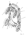
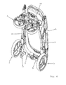
- cart 1 further comprises a folding mechanism 19 for folding the two back wheels 3 and the two front wheels 4 simultaneously from the drive position shown in Figs. 1 to 4 into a stow position shown in Fig. 7 .
- Folding mechanism or device 19 comprises an operating handle 20 separate from the carrier frame 5 such that the two back wheels 3 and the two front wheels 4 may be folded into the stow position independently of the collapsing mechanism 12 for bringing the carrier frame 5 into the collapsed position.
- the operating handle 20 is arranged at a front end of the bottom frame 2, between two front wheels 4.
- cart 1 is arranged in an upright position, in which front wheels 4 and back wheels 3 are lifted off a level ground.
- two foot elements 21 are arranged on the rear transverse frame member 9.
- the foot elements 21 may be extensions of lateral frame members 8.
- front wheels 4 and back wheels 3 may be arranged in parallel to each other.
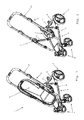
- front wheels 4 are pivoted into an intermediate folding position about an axis essentially perpendicular to the bottom frame 2(i.e. a vertical axis with respect to the drive position on the ground as shown in Figs. 1, 2 ). In the intermediate folding position, front wheels 4 are arranged essentially perpendicularly to back wheels 3.
- front wheels 4 are pivoted about transverse axes perpendicular to the longitudinal axis of cart 1 by approximately 90°.
- back wheels 3 are pivoted about axes essentially parallel to the longitudinal axis of cart 1 by approximately 90°.
- front wheels 4 and back wheels 3 are arranged in the stow position shown in Fig. 7 , in which front wheels 4 and back wheels 3 lie flat at the underside of bottom frame 2.
- the operating handle 20 is a push-and-pull handle being linearly movable along the main plane of the bottom frame 2.
- the folding mechanism 19 comprises a force transmitting device 22 housed inside the bottom frame 2.
- force transmitting device 22 comprises one tie rod 23 in each lateral frame member 8 of bottom frame 2.
- the tie rods 23 are multi-part in the shown embodiment.
- the opposite ends of tie rods 23 are connected to the operating handle 20 and back wheels 3, respectively.
- the folding mechanism 19 further comprises one sleeve element 24 around each lateral frame member 8.
- the sleeve elements 24 are connected to back wheels 3.
- Each sleeve element 24 has a guide rail 25 with sections inclined to the direction of the linear movement of tie rods 23.
- Sliding elements 31 are rigidly connected to ends of tie rods 23 and slide along first guide rails 25 of sleeve elements 24. In this way, an actuation of the operating handle 20 is transferred into the swiveling or pivoting motion of the two back wheels 3 into the stow position.
- the push-and-pull operating handle 20 is mounted on a transverse rod 26 extending perpendicularly to the direction of the pushing or pulling of the push-and-pull operating handle 20.
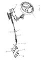
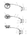
- the folding mechanism 19 further comprises an intermediary member 27 arranged between the operating handle 20 and the front wheel 4 (see Fig. 8a to 8d ).
- the intermediary member 27 has a second guide rail 28 which accomodates a slider formed by transverse rod 26. In this way, an actuation of the operating handle 20 is transferred into a swiveling or pivoting motion of the front wheel 4 into the stow position.
- the push-and-pull operating handle 20 comprises a handhold member 29 and a mounting member 30 mounted on the transverse rod 26 of bottom frame 2.
- the handhold member 29 is pivotably mounted on the mounting element 30.
Landscapes
- Engineering & Computer Science (AREA)
- Chemical & Material Sciences (AREA)
- Combustion & Propulsion (AREA)
- Transportation (AREA)
- Mechanical Engineering (AREA)
- Handcart (AREA)
Priority Applications (4)
| Application Number | Priority Date | Filing Date | Title |
|---|---|---|---|
| EP15180201.4A EP3127775B1 (fr) | 2015-08-07 | 2015-08-07 | Chariot |
| TW105123942A TWI607927B (zh) | 2015-08-07 | 2016-07-28 | 推車 |
| AU2016210708A AU2016210708A1 (en) | 2015-08-07 | 2016-08-04 | A Cart |
| CN201610635812.2A CN106627721A (zh) | 2015-08-07 | 2016-08-05 | 推车 |
Applications Claiming Priority (1)
| Application Number | Priority Date | Filing Date | Title |
|---|---|---|---|
| EP15180201.4A EP3127775B1 (fr) | 2015-08-07 | 2015-08-07 | Chariot |
Publications (2)
| Publication Number | Publication Date |
|---|---|
| EP3127775A1 true EP3127775A1 (fr) | 2017-02-08 |
| EP3127775B1 EP3127775B1 (fr) | 2019-10-02 |
Family
ID=53785555
Family Applications (1)
| Application Number | Title | Priority Date | Filing Date |
|---|---|---|---|
| EP15180201.4A Active EP3127775B1 (fr) | 2015-08-07 | 2015-08-07 | Chariot |
Country Status (4)
| Country | Link |
|---|---|
| EP (1) | EP3127775B1 (fr) |
| CN (1) | CN106627721A (fr) |
| AU (1) | AU2016210708A1 (fr) |
| TW (1) | TWI607927B (fr) |
Cited By (2)
| Publication number | Priority date | Publication date | Assignee | Title |
|---|---|---|---|---|
| CN110914136A (zh) * | 2017-07-18 | 2020-03-24 | 卡米耶·德·弗雷德 | 婴儿车支架和包括这种婴儿车支架的婴儿车 |
| WO2023078556A1 (fr) * | 2021-11-04 | 2023-05-11 | Mamas & Papas (Holdings) Limited | Poussette pliante |
Families Citing this family (7)
| Publication number | Priority date | Publication date | Assignee | Title |
|---|---|---|---|---|
| WO2019015791A1 (fr) * | 2017-07-21 | 2019-01-24 | Unique Product & Design Co., Ltd. | Chariot et structure de liaison de roue |
| KR102183943B1 (ko) * | 2017-07-24 | 2020-11-30 | 베이징 시아오미 모바일 소프트웨어 컴퍼니 리미티드 | 차륜 반전 기구 및 카트 프레임 |
| CN109291981B (zh) * | 2017-07-24 | 2023-11-07 | 上海宝糖科技有限公司 | 车轮翻转机构及推车车架 |
| CN108945075B (zh) * | 2018-08-17 | 2024-08-27 | 好孩子儿童用品有限公司 | 儿童推车 |
| CN109178077A (zh) | 2018-09-29 | 2019-01-11 | 好孩子儿童用品有限公司 | 折叠婴儿推车 |
| CN113511250B (zh) * | 2021-07-16 | 2023-01-31 | 好孩子儿童用品有限公司 | 儿童推车 |
| CN114852157B (zh) * | 2022-04-21 | 2024-05-03 | 福建欧仕儿童用品股份有限公司 | 一种可转换成汽车安全座椅底座的推车 |
Citations (6)
| Publication number | Priority date | Publication date | Assignee | Title |
|---|---|---|---|---|
| GB639439A (en) * | 1948-02-27 | 1950-06-28 | Adolf Mirecki | Improvements connected with folding pushcars or wheeled chairs |
| FR2323563A1 (fr) * | 1975-09-11 | 1977-04-08 | Mutsaerts Kinderwagenfabriek B | Poussette pliante |
| DE202005019055U1 (de) * | 2005-12-06 | 2006-02-23 | Etonico Industries Ltd. | Mehrzweckkinderwagen |
| WO2007025551A1 (fr) | 2005-09-02 | 2007-03-08 | Seed Production Aps | Landau |
| FR2926521A1 (fr) * | 2008-01-17 | 2009-07-24 | Chaudeurge Jean Michel Francoi | Chassis de poussette, notamment pour transporter un enfant |
| CN103448778A (zh) * | 2013-09-13 | 2013-12-18 | 中山市隆成日用制品有限公司 | 婴儿车前、后轮组的扁平化收折机构 |
-
2015
- 2015-08-07 EP EP15180201.4A patent/EP3127775B1/fr active Active
-
2016
- 2016-07-28 TW TW105123942A patent/TWI607927B/zh not_active IP Right Cessation
- 2016-08-04 AU AU2016210708A patent/AU2016210708A1/en not_active Abandoned
- 2016-08-05 CN CN201610635812.2A patent/CN106627721A/zh active Pending
Patent Citations (6)
| Publication number | Priority date | Publication date | Assignee | Title |
|---|---|---|---|---|
| GB639439A (en) * | 1948-02-27 | 1950-06-28 | Adolf Mirecki | Improvements connected with folding pushcars or wheeled chairs |
| FR2323563A1 (fr) * | 1975-09-11 | 1977-04-08 | Mutsaerts Kinderwagenfabriek B | Poussette pliante |
| WO2007025551A1 (fr) | 2005-09-02 | 2007-03-08 | Seed Production Aps | Landau |
| DE202005019055U1 (de) * | 2005-12-06 | 2006-02-23 | Etonico Industries Ltd. | Mehrzweckkinderwagen |
| FR2926521A1 (fr) * | 2008-01-17 | 2009-07-24 | Chaudeurge Jean Michel Francoi | Chassis de poussette, notamment pour transporter un enfant |
| CN103448778A (zh) * | 2013-09-13 | 2013-12-18 | 中山市隆成日用制品有限公司 | 婴儿车前、后轮组的扁平化收折机构 |
Cited By (2)
| Publication number | Priority date | Publication date | Assignee | Title |
|---|---|---|---|---|
| CN110914136A (zh) * | 2017-07-18 | 2020-03-24 | 卡米耶·德·弗雷德 | 婴儿车支架和包括这种婴儿车支架的婴儿车 |
| WO2023078556A1 (fr) * | 2021-11-04 | 2023-05-11 | Mamas & Papas (Holdings) Limited | Poussette pliante |
Also Published As
| Publication number | Publication date |
|---|---|
| TW201706173A (zh) | 2017-02-16 |
| CN106627721A (zh) | 2017-05-10 |
| EP3127775B1 (fr) | 2019-10-02 |
| TWI607927B (zh) | 2017-12-11 |
| AU2016210708A1 (en) | 2017-02-23 |
Similar Documents
| Publication | Publication Date | Title |
|---|---|---|
| EP3127775B1 (fr) | Chariot | |
| US10850760B2 (en) | Foldable wheeled carrier including wheel folding actuation handle | |
| EP3184401B1 (fr) | Poussette pour enfant | |
| CN109515507B (zh) | 儿童推车车架及儿童推车 | |
| US10322740B2 (en) | Stroller | |
| JP6008935B2 (ja) | 折り畳み式乳母車 | |
| EP2243684A1 (fr) | Chariot pliable | |
| US20080224451A1 (en) | Device For Transporting A Child | |
| CN108473152B (zh) | 能够转换成实用的前后双人婴儿车的单人婴儿车 | |
| TWI799033B (zh) | 車架結構及兒童車 | |
| EP3436327B1 (fr) | Chariot | |
| TW201348046A (zh) | 手推桿滑動式嬰兒車 | |
| US6416076B1 (en) | Collapsible stroller | |
| CN101665115B (zh) | 婴儿推车 | |
| CN207790800U (zh) | 一种婴儿车 | |
| CN112319591B (zh) | 儿童推车 | |
| CN210174950U (zh) | 用于婴儿车车架的支架及设有该支架的婴儿车车架 | |
| CN201264630Y (zh) | 婴儿车骨架之收折机构 | |
| CN104340255B (zh) | 车架 | |
| CN201102562Y (zh) | 儿童推车 | |
| CN219821540U (zh) | 一种推车的收合结构 | |
| CN107921984A (zh) | 儿童推车的折叠框架以及相应的推车 | |
| CN223290915U (zh) | 儿童折叠推车 | |
| CN212529787U (zh) | 婴儿车车架组件及婴儿车 | |
| WO2025120561A1 (fr) | Mécanisme de pliage de cadre de poussette |
Legal Events
| Date | Code | Title | Description |
|---|---|---|---|
| PUAI | Public reference made under article 153(3) epc to a published international application that has entered the european phase |
Free format text: ORIGINAL CODE: 0009012 |
|
| STAA | Information on the status of an ep patent application or granted ep patent |
Free format text: STATUS: THE APPLICATION HAS BEEN PUBLISHED |
|
| AK | Designated contracting states |
Kind code of ref document: A1 Designated state(s): AL AT BE BG CH CY CZ DE DK EE ES FI FR GB GR HR HU IE IS IT LI LT LU LV MC MK MT NL NO PL PT RO RS SE SI SK SM TR |
|
| AX | Request for extension of the european patent |
Extension state: BA ME |
|
| STAA | Information on the status of an ep patent application or granted ep patent |
Free format text: STATUS: REQUEST FOR EXAMINATION WAS MADE |
|
| 17P | Request for examination filed |
Effective date: 20170726 |
|
| RBV | Designated contracting states (corrected) |
Designated state(s): AL AT BE BG CH CY CZ DE DK EE ES FI FR GB GR HR HU IE IS IT LI LT LU LV MC MK MT NL NO PL PT RO RS SE SI SK SM TR |
|
| STAA | Information on the status of an ep patent application or granted ep patent |
Free format text: STATUS: EXAMINATION IS IN PROGRESS |
|
| 17Q | First examination report despatched |
Effective date: 20180308 |
|
| GRAP | Despatch of communication of intention to grant a patent |
Free format text: ORIGINAL CODE: EPIDOSNIGR1 |
|
| STAA | Information on the status of an ep patent application or granted ep patent |
Free format text: STATUS: GRANT OF PATENT IS INTENDED |
|
| INTG | Intention to grant announced |
Effective date: 20190312 |
|
| GRAS | Grant fee paid |
Free format text: ORIGINAL CODE: EPIDOSNIGR3 |
|
| GRAA | (expected) grant |
Free format text: ORIGINAL CODE: 0009210 |
|
| STAA | Information on the status of an ep patent application or granted ep patent |
Free format text: STATUS: THE PATENT HAS BEEN GRANTED |
|
| AK | Designated contracting states |
Kind code of ref document: B1 Designated state(s): AL AT BE BG CH CY CZ DE DK EE ES FI FR GB GR HR HU IE IS IT LI LT LU LV MC MK MT NL NO PL PT RO RS SE SI SK SM TR |
|
| REG | Reference to a national code |
Ref country code: GB Ref legal event code: FG4D |
|
| REG | Reference to a national code |
Ref country code: CH Ref legal event code: EP Ref country code: AT Ref legal event code: REF Ref document number: 1185866 Country of ref document: AT Kind code of ref document: T Effective date: 20191015 |
|
| REG | Reference to a national code |
Ref country code: DE Ref legal event code: R096 Ref document number: 602015038956 Country of ref document: DE |
|
| REG | Reference to a national code |
Ref country code: IE Ref legal event code: FG4D |
|
| REG | Reference to a national code |
Ref country code: NL Ref legal event code: MP Effective date: 20191002 |
|
| REG | Reference to a national code |
Ref country code: LT Ref legal event code: MG4D |
|
| REG | Reference to a national code |
Ref country code: AT Ref legal event code: MK05 Ref document number: 1185866 Country of ref document: AT Kind code of ref document: T Effective date: 20191002 |
|
| PG25 | Lapsed in a contracting state [announced via postgrant information from national office to epo] |
Ref country code: ES Free format text: LAPSE BECAUSE OF FAILURE TO SUBMIT A TRANSLATION OF THE DESCRIPTION OR TO PAY THE FEE WITHIN THE PRESCRIBED TIME-LIMIT Effective date: 20191002 Ref country code: SE Free format text: LAPSE BECAUSE OF FAILURE TO SUBMIT A TRANSLATION OF THE DESCRIPTION OR TO PAY THE FEE WITHIN THE PRESCRIBED TIME-LIMIT Effective date: 20191002 Ref country code: LV Free format text: LAPSE BECAUSE OF FAILURE TO SUBMIT A TRANSLATION OF THE DESCRIPTION OR TO PAY THE FEE WITHIN THE PRESCRIBED TIME-LIMIT Effective date: 20191002 Ref country code: AT Free format text: LAPSE BECAUSE OF FAILURE TO SUBMIT A TRANSLATION OF THE DESCRIPTION OR TO PAY THE FEE WITHIN THE PRESCRIBED TIME-LIMIT Effective date: 20191002 Ref country code: PT Free format text: LAPSE BECAUSE OF FAILURE TO SUBMIT A TRANSLATION OF THE DESCRIPTION OR TO PAY THE FEE WITHIN THE PRESCRIBED TIME-LIMIT Effective date: 20200203 Ref country code: FI Free format text: LAPSE BECAUSE OF FAILURE TO SUBMIT A TRANSLATION OF THE DESCRIPTION OR TO PAY THE FEE WITHIN THE PRESCRIBED TIME-LIMIT Effective date: 20191002 Ref country code: BG Free format text: LAPSE BECAUSE OF FAILURE TO SUBMIT A TRANSLATION OF THE DESCRIPTION OR TO PAY THE FEE WITHIN THE PRESCRIBED TIME-LIMIT Effective date: 20200102 Ref country code: NO Free format text: LAPSE BECAUSE OF FAILURE TO SUBMIT A TRANSLATION OF THE DESCRIPTION OR TO PAY THE FEE WITHIN THE PRESCRIBED TIME-LIMIT Effective date: 20200102 Ref country code: PL Free format text: LAPSE BECAUSE OF FAILURE TO SUBMIT A TRANSLATION OF THE DESCRIPTION OR TO PAY THE FEE WITHIN THE PRESCRIBED TIME-LIMIT Effective date: 20191002 Ref country code: LT Free format text: LAPSE BECAUSE OF FAILURE TO SUBMIT A TRANSLATION OF THE DESCRIPTION OR TO PAY THE FEE WITHIN THE PRESCRIBED TIME-LIMIT Effective date: 20191002 Ref country code: NL Free format text: LAPSE BECAUSE OF FAILURE TO SUBMIT A TRANSLATION OF THE DESCRIPTION OR TO PAY THE FEE WITHIN THE PRESCRIBED TIME-LIMIT Effective date: 20191002 Ref country code: GR Free format text: LAPSE BECAUSE OF FAILURE TO SUBMIT A TRANSLATION OF THE DESCRIPTION OR TO PAY THE FEE WITHIN THE PRESCRIBED TIME-LIMIT Effective date: 20200103 |
|
| PG25 | Lapsed in a contracting state [announced via postgrant information from national office to epo] |
Ref country code: RS Free format text: LAPSE BECAUSE OF FAILURE TO SUBMIT A TRANSLATION OF THE DESCRIPTION OR TO PAY THE FEE WITHIN THE PRESCRIBED TIME-LIMIT Effective date: 20191002 Ref country code: HR Free format text: LAPSE BECAUSE OF FAILURE TO SUBMIT A TRANSLATION OF THE DESCRIPTION OR TO PAY THE FEE WITHIN THE PRESCRIBED TIME-LIMIT Effective date: 20191002 Ref country code: CZ Free format text: LAPSE BECAUSE OF FAILURE TO SUBMIT A TRANSLATION OF THE DESCRIPTION OR TO PAY THE FEE WITHIN THE PRESCRIBED TIME-LIMIT Effective date: 20191002 Ref country code: IS Free format text: LAPSE BECAUSE OF FAILURE TO SUBMIT A TRANSLATION OF THE DESCRIPTION OR TO PAY THE FEE WITHIN THE PRESCRIBED TIME-LIMIT Effective date: 20200224 |
|
| PG25 | Lapsed in a contracting state [announced via postgrant information from national office to epo] |
Ref country code: AL Free format text: LAPSE BECAUSE OF FAILURE TO SUBMIT A TRANSLATION OF THE DESCRIPTION OR TO PAY THE FEE WITHIN THE PRESCRIBED TIME-LIMIT Effective date: 20191002 |
|
| REG | Reference to a national code |
Ref country code: DE Ref legal event code: R097 Ref document number: 602015038956 Country of ref document: DE |
|
| PG2D | Information on lapse in contracting state deleted |
Ref country code: IS |
|
| PG25 | Lapsed in a contracting state [announced via postgrant information from national office to epo] |
Ref country code: RO Free format text: LAPSE BECAUSE OF FAILURE TO SUBMIT A TRANSLATION OF THE DESCRIPTION OR TO PAY THE FEE WITHIN THE PRESCRIBED TIME-LIMIT Effective date: 20191002 Ref country code: DK Free format text: LAPSE BECAUSE OF FAILURE TO SUBMIT A TRANSLATION OF THE DESCRIPTION OR TO PAY THE FEE WITHIN THE PRESCRIBED TIME-LIMIT Effective date: 20191002 Ref country code: EE Free format text: LAPSE BECAUSE OF FAILURE TO SUBMIT A TRANSLATION OF THE DESCRIPTION OR TO PAY THE FEE WITHIN THE PRESCRIBED TIME-LIMIT Effective date: 20191002 Ref country code: IS Free format text: LAPSE BECAUSE OF FAILURE TO SUBMIT A TRANSLATION OF THE DESCRIPTION OR TO PAY THE FEE WITHIN THE PRESCRIBED TIME-LIMIT Effective date: 20200202 |
|
| PLBE | No opposition filed within time limit |
Free format text: ORIGINAL CODE: 0009261 |
|
| STAA | Information on the status of an ep patent application or granted ep patent |
Free format text: STATUS: NO OPPOSITION FILED WITHIN TIME LIMIT |
|
| PG25 | Lapsed in a contracting state [announced via postgrant information from national office to epo] |
Ref country code: SK Free format text: LAPSE BECAUSE OF FAILURE TO SUBMIT A TRANSLATION OF THE DESCRIPTION OR TO PAY THE FEE WITHIN THE PRESCRIBED TIME-LIMIT Effective date: 20191002 Ref country code: SM Free format text: LAPSE BECAUSE OF FAILURE TO SUBMIT A TRANSLATION OF THE DESCRIPTION OR TO PAY THE FEE WITHIN THE PRESCRIBED TIME-LIMIT Effective date: 20191002 Ref country code: IT Free format text: LAPSE BECAUSE OF FAILURE TO SUBMIT A TRANSLATION OF THE DESCRIPTION OR TO PAY THE FEE WITHIN THE PRESCRIBED TIME-LIMIT Effective date: 20191002 |
|
| 26N | No opposition filed |
Effective date: 20200703 |
|
| PG25 | Lapsed in a contracting state [announced via postgrant information from national office to epo] |
Ref country code: SI Free format text: LAPSE BECAUSE OF FAILURE TO SUBMIT A TRANSLATION OF THE DESCRIPTION OR TO PAY THE FEE WITHIN THE PRESCRIBED TIME-LIMIT Effective date: 20191002 |
|
| PG25 | Lapsed in a contracting state [announced via postgrant information from national office to epo] |
Ref country code: MC Free format text: LAPSE BECAUSE OF FAILURE TO SUBMIT A TRANSLATION OF THE DESCRIPTION OR TO PAY THE FEE WITHIN THE PRESCRIBED TIME-LIMIT Effective date: 20191002 |
|
| REG | Reference to a national code |
Ref country code: CH Ref legal event code: PL |
|
| PG25 | Lapsed in a contracting state [announced via postgrant information from national office to epo] |
Ref country code: LI Free format text: LAPSE BECAUSE OF NON-PAYMENT OF DUE FEES Effective date: 20200831 Ref country code: LU Free format text: LAPSE BECAUSE OF NON-PAYMENT OF DUE FEES Effective date: 20200807 Ref country code: CH Free format text: LAPSE BECAUSE OF NON-PAYMENT OF DUE FEES Effective date: 20200831 |
|
| REG | Reference to a national code |
Ref country code: BE Ref legal event code: MM Effective date: 20200831 |
|
| PG25 | Lapsed in a contracting state [announced via postgrant information from national office to epo] |
Ref country code: IE Free format text: LAPSE BECAUSE OF NON-PAYMENT OF DUE FEES Effective date: 20200807 Ref country code: BE Free format text: LAPSE BECAUSE OF NON-PAYMENT OF DUE FEES Effective date: 20200831 |
|
| PGFP | Annual fee paid to national office [announced via postgrant information from national office to epo] |
Ref country code: FR Payment date: 20210823 Year of fee payment: 7 |
|
| PGFP | Annual fee paid to national office [announced via postgrant information from national office to epo] |
Ref country code: GB Payment date: 20210824 Year of fee payment: 7 Ref country code: DE Payment date: 20210819 Year of fee payment: 7 |
|
| PG25 | Lapsed in a contracting state [announced via postgrant information from national office to epo] |
Ref country code: TR Free format text: LAPSE BECAUSE OF FAILURE TO SUBMIT A TRANSLATION OF THE DESCRIPTION OR TO PAY THE FEE WITHIN THE PRESCRIBED TIME-LIMIT Effective date: 20191002 Ref country code: MT Free format text: LAPSE BECAUSE OF FAILURE TO SUBMIT A TRANSLATION OF THE DESCRIPTION OR TO PAY THE FEE WITHIN THE PRESCRIBED TIME-LIMIT Effective date: 20191002 Ref country code: CY Free format text: LAPSE BECAUSE OF FAILURE TO SUBMIT A TRANSLATION OF THE DESCRIPTION OR TO PAY THE FEE WITHIN THE PRESCRIBED TIME-LIMIT Effective date: 20191002 |
|
| PG25 | Lapsed in a contracting state [announced via postgrant information from national office to epo] |
Ref country code: MK Free format text: LAPSE BECAUSE OF FAILURE TO SUBMIT A TRANSLATION OF THE DESCRIPTION OR TO PAY THE FEE WITHIN THE PRESCRIBED TIME-LIMIT Effective date: 20191002 |
|
| REG | Reference to a national code |
Ref country code: DE Ref legal event code: R119 Ref document number: 602015038956 Country of ref document: DE |
|
| GBPC | Gb: european patent ceased through non-payment of renewal fee |
Effective date: 20220807 |
|
| PG25 | Lapsed in a contracting state [announced via postgrant information from national office to epo] |
Ref country code: FR Free format text: LAPSE BECAUSE OF NON-PAYMENT OF DUE FEES Effective date: 20220831 Ref country code: DE Free format text: LAPSE BECAUSE OF NON-PAYMENT OF DUE FEES Effective date: 20230301 |
|
| PG25 | Lapsed in a contracting state [announced via postgrant information from national office to epo] |
Ref country code: GB Free format text: LAPSE BECAUSE OF NON-PAYMENT OF DUE FEES Effective date: 20220807 |