EP3127778A1 - Doppelte ölkanalstruktur eines lenkmotors - Google Patents
Doppelte ölkanalstruktur eines lenkmotors Download PDFInfo
- Publication number
- EP3127778A1 EP3127778A1 EP14887872.1A EP14887872A EP3127778A1 EP 3127778 A1 EP3127778 A1 EP 3127778A1 EP 14887872 A EP14887872 A EP 14887872A EP 3127778 A1 EP3127778 A1 EP 3127778A1
- Authority
- EP
- European Patent Office
- Prior art keywords
- oil
- cavity
- distributor
- valve
- wall
- Prior art date
- Legal status (The legal status is an assumption and is not a legal conclusion. Google has not performed a legal analysis and makes no representation as to the accuracy of the status listed.)
- Granted
Links
- 238000004891 communication Methods 0.000 claims abstract description 36
- 230000003139 buffering effect Effects 0.000 claims abstract description 19
- 238000013016 damping Methods 0.000 claims description 10
- 238000004804 winding Methods 0.000 claims description 6
- 238000005192 partition Methods 0.000 abstract 1
- 238000011161 development Methods 0.000 description 2
- 230000002452 interceptive effect Effects 0.000 description 2
- 238000004519 manufacturing process Methods 0.000 description 2
- 238000007789 sealing Methods 0.000 description 2
- 238000010521 absorption reaction Methods 0.000 description 1
- 230000009286 beneficial effect Effects 0.000 description 1
- 230000007547 defect Effects 0.000 description 1
- 238000013461 design Methods 0.000 description 1
- 239000012530 fluid Substances 0.000 description 1
- 238000000034 method Methods 0.000 description 1
- 238000012986 modification Methods 0.000 description 1
- 230000004048 modification Effects 0.000 description 1
- 230000000149 penetrating effect Effects 0.000 description 1
- 230000035939 shock Effects 0.000 description 1
Images




Classifications
-
- H—ELECTRICITY
- H02—GENERATION; CONVERSION OR DISTRIBUTION OF ELECTRIC POWER
- H02K—DYNAMO-ELECTRIC MACHINES
- H02K5/00—Casings; Enclosures; Supports
- H02K5/24—Casings; Enclosures; Supports specially adapted for suppression or reduction of noise or vibrations
-
- B—PERFORMING OPERATIONS; TRANSPORTING
- B62—LAND VEHICLES FOR TRAVELLING OTHERWISE THAN ON RAILS
- B62D—MOTOR VEHICLES; TRAILERS
- B62D5/00—Power-assisted or power-driven steering
- B62D5/04—Power-assisted or power-driven steering electrical, e.g. using an electric servo-motor connected to, or forming part of, the steering gear
-
- B—PERFORMING OPERATIONS; TRANSPORTING
- B62—LAND VEHICLES FOR TRAVELLING OTHERWISE THAN ON RAILS
- B62D—MOTOR VEHICLES; TRAILERS
- B62D5/00—Power-assisted or power-driven steering
- B62D5/04—Power-assisted or power-driven steering electrical, e.g. using an electric servo-motor connected to, or forming part of, the steering gear
- B62D5/0418—Electric motor acting on road wheel carriers
-
- B—PERFORMING OPERATIONS; TRANSPORTING
- B62—LAND VEHICLES FOR TRAVELLING OTHERWISE THAN ON RAILS
- B62D—MOTOR VEHICLES; TRAILERS
- B62D7/00—Steering linkage; Stub axles or their mountings
- B62D7/02—Steering linkage; Stub axles or their mountings for pivoted bogies
-
- B—PERFORMING OPERATIONS; TRANSPORTING
- B62—LAND VEHICLES FOR TRAVELLING OTHERWISE THAN ON RAILS
- B62D—MOTOR VEHICLES; TRAILERS
- B62D7/00—Steering linkage; Stub axles or their mountings
- B62D7/22—Arrangements for reducing or eliminating reaction, e.g. vibration, from parts, e.g. wheels, of the steering system
-
- H—ELECTRICITY
- H02—GENERATION; CONVERSION OR DISTRIBUTION OF ELECTRIC POWER
- H02K—DYNAMO-ELECTRIC MACHINES
- H02K5/00—Casings; Enclosures; Supports
- H02K5/04—Casings or enclosures characterised by the shape, form or construction thereof
-
- H—ELECTRICITY
- H02—GENERATION; CONVERSION OR DISTRIBUTION OF ELECTRIC POWER
- H02K—DYNAMO-ELECTRIC MACHINES
- H02K7/00—Arrangements for handling mechanical energy structurally associated with dynamo-electric machines, e.g. structural association with mechanical driving motors or auxiliary dynamo-electric machines
- H02K7/14—Structural association with mechanical loads, e.g. with hand-held machine tools or fans
- H02K7/16—Structural association with mechanical loads, e.g. with hand-held machine tools or fans for operation above the critical speed of vibration of the rotating parts
Definitions
- the present application relates to the technical field of oil passages of motors, especially to a double oil passage structure of a steering motor.
- an electric power steering system is the development direction of automobile steering systems.
- the steering power of the system is directly provided by a steering motor some components required by traditional hydraulic power steering systems are then omitted, and hence not only is energy saved but also the environment is protected.
- the system further has features that it is easy to be adjusted and flexible to be assembled and the steering power can be provided under various circumstances.
- a torque sensor detects the veer of the steering wheel and the extent of the torque, and transmits a voltage signal to an electronic control unit.
- the electronic control unit sends an instruction to a steering motor controller according to the torque voltage signal, the steering direction, and the automobile speed signal detected by the torque sensor, and makes the steering motor output a steering power torque with corresponding magnitude and direction, thereby producing auxiliary power.
- the electronic control unit will not send any instruction to the motor controller, and the motor does not work.
- Existing steering motors are generally provided with a variety of oil passages, such as oil passages for shock absorption oil supply, oil passages for braking oil supply, oil passages for hoist oil supply, etc; however, these oil passages are all designed independently and assembled separately, such that each of the oil passages are isolated from each other; therefore, too many independent oil passages occupy too much internal space of the steering motor, such that the remained available space inside the steering motor is reduced correspondingly. In order to avoid the affect, the whole volume of the steering motor is often increased, which not only wastes resources but also increases manufacturing cost.
- a purpose of the present application is to provide a double oil passage structure of a steering motor, which aims to overcome the defects in the prior art that each oil passage inside the steering motor is designed independently and hence occupies a relatively large internal space of the steering motor, such that the volume of the steering motor is increased, and thus resources are wasted and manufacturing cost is increased.
- a double oil passage structure of a steering motor includes an upper cover buffering assembly and an oil distributor; the oil distributor is arranged under the upper cover buffering assembly, and is fitted with the upper cover buffering assembly to form a sealed axial cavity; the oil distributor is provided with an oil flow passage arranged radially and in communication with the axial cavity; the oil distributor is provided with an oil inlet; a hollow column that is arranged axially with an inner cavity extends upwards and downwards respectively inside the oil distributor; an inner wall of the hollow column is provided with an oil flow opening in communication the oil flow passage; an inner side of the hollow column is provided with a reversing valve which has a valve core; an inner sidewall of the hollow column and an outer wall of the reversing cavity form a first radial cavity; the first radial cavity is embedded with a pin; the first radial cavity is separated by the pin to form an oil-distributor oil-inlet cavity and an oil-distributor oil-outlet
- the upper cover buffering assembly includes an upper cover and a butterfly-shaped elastic diaphragm, and the elastic diaphragm is embedded into a lower edge of an inner side of the upper cover and fitted with the oil distributor through a fastener to form a seal.
- a cylinder assembly is arranged under the oil distributor; the cylinder assembly comprises a cylinder which is abutted against a lower surface of the oil distributor and has openings defined at two ends thereof, an elastic oil bag arranged inside the cylinder and having an upper end connected fixedly, and a piston that is fixedly connected to a lower end of the elastic oil bag and capable of moving axially inside the cylinder.
- the upper end of the elastic oil bag is provided with an opening, and an edge of the opening is fixedly connected with the cylinder; the oil distributor is provided with a damp hole which is in communication with the axial cavity and the elastic oil bag respectively.
- an aperture of the damping hole is smaller than a caliber of the opening of the upper end of the elastic oil bag.
- the reversing valve includes a winding coil positioned under the oil distributor and sheathed around a periphery of the valve cavity.
- a center of the valve core is provided with a circular through-hole; a plurality of open ring slots are arranged around an outer wall of the valve core; the open ring slots are embedded internally with an O-shaped seal ring.
- a bottom end of the valve core is provided with a valve tail, and the valve tail extends downwards to the bottom end of the valve cavity; both an inner wall and an outer wall of the valve tail are provided with open slots; a hollow bellows is embedded inside the open slots; the hollow bellows extends downwards beyond the bottom end of the valve core.
- an inner wall of a top end of the hollow column is sheathed with a deep groove ball bearing; a hollow sleeve is sheathed in an inner ring of the deep groove ball bearing; an inner diameter of the hollow sleeve is smaller than an inner diameter of the circular through-hole defined in the valve core.
- a pipeline sheath is arranged inside the hollow sleeve; the pipeline sheath extends downwards along the inner wall of the hollow sleeve and beyond the hollow bellows.
- the double oil passage structure of the steering motor forms an oil passage which starts from the oil distributor into the oil inlet cavity, passes through the oil-flow ring slot on the valve core and the oil-distributor oil-outlet cavity, and enters the axial cavity; and forms another oil passage which starts from oil-distributor oil-inlet cavity, passes through the oil flow hole of the reversing valve, enters the second radial cavity, and is in communication with the oil-outlet passage.
- the passages are divided into two non-interfering branch oil passages, the space occupied by the oil passages is reduced, the volume of the steering motor is further reduced, and resources as well as cost are saved.
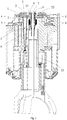
- the embodiment provides a double oil passage structure of a steering motor, and the double oil passage structure is arranged inside the steering motor and includes an upper cover buffering assembly 1 and an oil distributor 2; the oil distributor 2 is arranged under the upper cover buffering assembly 1, and the upper cover buffering assembly 1 and the oil distributor 2 are fitted with each other to form a sealed axial cavity 4;
- the oil distributor 2 is provided with a hollow column 21 which respectively extends upwards downwards and is arranged axially; the hollow column 21 is provided with an inner cavity.
- the oil distributor 2 is further provided with an oil inlet 22 and an oil flow passage 23 arranged radially.
- An inner wall of the hollow column 21 is provided with an oil flow opening which is in communication with the oil flow passage 23.
- the oil flow passage 23 is in communication with an inner cavity of the hollow column 21 through the oil flow opening, and the oil flow passage 23 is further in communication with the axial cavity 4.
- An inner side of the hollow column 21 is provided with a reversing valve 3, and the reversing valve 3 is provided with a valve core 31 and a valve cavity 32.
- An inner wall of the hollow column 21 and an outer wall of the valve cavity 32 form a first radial cavity.
- the first radial cavity is embedded with a pin 7.
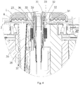
- the first radial cavity is separated by the pin 7 to form an oil-distributor oil-inlet cavity 24 and an oil-distributor oil-outlet cavity 25 which are independent from each other; wherein the oil-distributor oil-inlet cavity 24 is in communication with the oil inlet 22, and the oil-distributor oil-outlet cavity 25 is in communication with the axial cavity 4.
- An upper portion of a sidewall of the valve cavity 32 is provided with a reversing-valve oil-flow passage 33 arranged to penetrate radially.
- An axial lower portion of the reversing-valve oil-flow passage 33 is provided with an oil flow hole 34 arranged radially.
- an oil-flow ring slot 35 with a semicircle shaped section is arranged around an upper portion of an outer wall of the valve core 31; the oil-flow ring slot 35 is respectively in communication with the oil-distributor oil-inlet cavity 24 and the oil-distributor oil-outlet cavity 25.
- a second radial cavity 36 is formed between an outer wall of a lower end of the valve core 31 and an inner wall of a lower portion of the valve cavity 32.
- a lower portion of the valve cavity 32 is provided with an oil outlet 37, and the oil outlet 37 is in communication with the second radial cavity 36.
- the oil-distributor oil-inlet cavity 24 is in communication with the reversing-valve oil-flow passage 33, the oil-flow ring slot 35, the oil-distributor oil-outlet cavity 25, and the axial cavity 4 so as to form an oil passage.
- the oil passage is configured for the oil supply to a steering motor hydraulic damping system and the hoist oil supply.
- the oil-distributor oil-inlet cavity 24 is in communication with the oil flow hole 34, the second radial cavity 36, and the oil outlet 37 so as to form another oil passage which is configured for the oil supply for steering motor braking.
- the sealed axial cavity 4 is formed by fitting the upper cover buffering assembly 1 with the oil distributor 2; both the oil-distributor oil-outlet cavity 25 which is in communication with the axial cavity 4 and the reversing-valve oil-flow passage 33 are in communication with the oil-distributor oil-inlet cavity 24 through the oil-flow ring slot 35; the second radial cavity 36 is in communication with the oil flow passage 34, the oil-distributor oil-inlet cavity 24 and the oil outlet 37.
- the upper cover buffering assembly 1 includes an upper cover 11 and an elastic diaphragm 12, wherein, the elastic diaphragm 12 is butterfly-shaped.
- the elastic diaphragm 12 is embedded into a lower margin of the inner side of the upper cover 11 to seal and fasten.
- the structure of the oil distributor 2 matches with and corresponds to the structure of the upper cover buffering assembly 1; the oil distributor 2 and the upper cover buffering assembly 1 are fitted with each other and connected hermetically through a fastener.
- the upper cover buffering assembly 1 and the oil distributor 2 can also adopt other types of structures.
- a cylinder assembly 5 is arranged under the oil distributor 2; the cylinder assembly 5 includes a cylinder 51, an elastic oil bag 52 and a piston 53.
- the cylinder 51 is a hollow columnar structure with openings defined at two ends thereof, and an upper end of the cylinder 51 is abutted against a lower surface of the oil distributor 2; both the elastic oil bag 52 and the piston 53 are arranged in the cylinder 51; the elastic oil bag 52 is a saccular elastic diaphragm with an opening defined at an upper end thereof, and a tail end of the elastic oil bag 52 is fixedly connected with an upper end of the piston 53; the piston 53 is capable of moving axially inside the cylinder 51.
- An edge of the opening at the upper end of the elastic oil bag 52 is fixedly connected with an inner wall of the opening at the upper end of the cylinder 51, thereby forming a seal for the opening of the cylinder 51. Furthermore, the opening of the elastic oil bag 52 is hermetically communicated with the axial cavity 4 through the oil distributor 2, thereby forming an oil passage.
- An undersurface of the bottom end of the oil distributor 2 is provided with a damping hole 26, and the damping hole 26 is arranged to be aligned with the opening at the upper end of the elastic oil bag 52, in this way, the elastic oil bag 52 is in hermetical communication with the axial cavity 4 through the damping hole 26.
- the elastic oil bag 52 can be in hermetical communication with the axial cavity 4 in other ways, such as a pipe connection or a passage connection, etc.
- an aperture of the damping hole 26 is smaller than a caliber of the opening of the elastic oil bag 52.
- the reversing valve 3 is an electromagnetic reversing valve.
- the reversing valve 3 further includes a winding coil 39.
- the winding coil 29 is sheathed around an outer wall of the valve cavity 32; the outer wall is provided with an axial locating flange; the winding coil 39 is located below the hollow column 21 and above the locating flange of the outer wall of the valve cavity 32.
- other types of reversing valves can also be adopted.
- a center of the valve core 31 is provided with a circular through-hole; a plurality of open ring slots are arranged around an outer wall of the valve core 31; each of the open ring slots is embedded internally with an O-shaped seal ring 38.
- the oil-flow ring slot 35 and the oil flow passage 23 are staggered; the reversing-valve oil-flow passage 33 is blocked by an outer wall of the valve core 31.
- the second radial cavity 36 is in communication with the oil-distributor oil-inlet cavity 24 through the oil flow hole 34, that is, an oil passage formed by the oil-distributor oil-inlet cavity 24 and the second radial cavity 36 forms a clear passage, and an oil passage formed by the oil-distributor oil-inlet cavity 24, the axial cavity 4 and the elastic oil bag 52 is blocked.
- the whole valve core 31 moves down, the oil-flow ring slot 35 is aligned with and in communication with the oil flow passage 33; the O-shaped seal ring 38 at a lower cone of the valve core 31 compresses a circular cone at the bottom of the valve core 32, that is, the second radial cavity 36 is blocked.
- the oil passage formed by the oil-distributor oil-inlet cavity 24, the axial cavity 4 and the elastic oil bag 52 forms a clear passage.
- the oil passage formed by the oil-distributor oil-inlet cavity 24 and the second radial cavity 36 is blocked.
- the reversing and switch function of the reversing valve 3 achieves a switch between the two oil passages, without interference.
- the bottom end of the valve core 31 is provided with a valve tail, and the valve tail extends downwards beyond the bottom end of the valve cavity 32; both an inner wall and an outer wall of the valve tail are provided with open slots which each penetrate in a circumferential direction.
- a hollow bellows 6 is embedded inside each open slot; the hollow bellows 6 extends downwards beyond the bottom end of the valve core 31.
- a top end of an inner wall of the hollow column 21 is sheathed around a deep groove ball bearing 8.
- a hollow sleeve 9 is sheathed in an inner ring of the deep groove ball bearing 8.
- the valve core 31 is provided with a circular through-hole penetrating the valve core 31 from top to bottom.
- An inner diameter of the hollow sleeve 9 is smaller than an inner diameter of the circular through-hole.
- the top end of the inner wall of the hollow column 21 can also be sheathed around other types of bearings.
- a pipeline sheath 10 is arranged inside the hollow sleeve 9.
- the pipeline sheath 10 extends downwards along the inner wall of the hollow sleeve 9 and beyond the bottom end of the valve core 31, and further enters the hollow bellows 6.
- the hollow bellows 6 and the hollow sleeve 9 support and locate the pipeline sheath 10.
- the pipeline sheath 10 is configured to be sheathed around a hand brake stayguy.
- the arrangement of the hand brake stayguy can also adopts other methods, and the pipeline sheath 10 can also be configured to arrange other pipelines.
Landscapes
- Engineering & Computer Science (AREA)
- Chemical & Material Sciences (AREA)
- Combustion & Propulsion (AREA)
- Transportation (AREA)
- Mechanical Engineering (AREA)
- Power Engineering (AREA)
- Power Steering Mechanism (AREA)
- Fluid-Damping Devices (AREA)
- Combined Devices Of Dampers And Springs (AREA)
- Vibration Dampers (AREA)
- Multiple-Way Valves (AREA)
- Steering-Linkage Mechanisms And Four-Wheel Steering (AREA)
- Magnetically Actuated Valves (AREA)
- Motor Or Generator Cooling System (AREA)
Priority Applications (1)
| Application Number | Priority Date | Filing Date | Title |
|---|---|---|---|
| PL14887872T PL3127778T3 (pl) | 2014-03-31 | 2014-04-02 | Podwójna struktura kanałów olejowych silnika wspomagania układu kierowniczego |
Applications Claiming Priority (2)
| Application Number | Priority Date | Filing Date | Title |
|---|---|---|---|
| PCT/CN2014/074346 WO2015149207A1 (zh) | 2014-03-31 | 2014-03-31 | 一种转向电机的减震机构 |
| PCT/CN2014/074600 WO2015149296A1 (zh) | 2014-03-31 | 2014-04-02 | 一种转向电机的双油道结构 |
Publications (3)
| Publication Number | Publication Date |
|---|---|
| EP3127778A1 true EP3127778A1 (de) | 2017-02-08 |
| EP3127778A4 EP3127778A4 (de) | 2017-11-22 |
| EP3127778B1 EP3127778B1 (de) | 2019-07-24 |
Family
ID=54239201
Family Applications (2)
| Application Number | Title | Priority Date | Filing Date |
|---|---|---|---|
| EP14888401.8A Active EP3128652B1 (de) | 2014-03-31 | 2014-03-31 | Stossdämpfungsmechanismus eines lenkmotors |
| EP14887872.1A Active EP3127778B1 (de) | 2014-03-31 | 2014-04-02 | Doppelte ölkanalstruktur eines lenkmotors |
Family Applications Before (1)
| Application Number | Title | Priority Date | Filing Date |
|---|---|---|---|
| EP14888401.8A Active EP3128652B1 (de) | 2014-03-31 | 2014-03-31 | Stossdämpfungsmechanismus eines lenkmotors |
Country Status (8)
| Country | Link |
|---|---|
| US (2) | US10348154B2 (de) |
| EP (2) | EP3128652B1 (de) |
| JP (2) | JP6386078B2 (de) |
| KR (2) | KR102128148B1 (de) |
| CN (2) | CN106104983B (de) |
| ES (2) | ES2794086T3 (de) |
| PL (1) | PL3127778T3 (de) |
| WO (2) | WO2015149207A1 (de) |
Families Citing this family (9)
| Publication number | Priority date | Publication date | Assignee | Title |
|---|---|---|---|---|
| JP6386077B2 (ja) * | 2014-03-31 | 2018-09-05 | 深▲せん▼市智行単軸双輪駆動技術有限公司 | ステアリングモーター |
| CN106233588B (zh) * | 2014-03-31 | 2019-02-01 | 深圳市智行单轴双轮驱动技术有限公司 | 一种转向电机 |
| CN106104983B (zh) * | 2014-03-31 | 2018-08-17 | 深圳市智行单轴双轮驱动技术有限公司 | 一种转向电机的减震机构 |
| CN106926899B (zh) * | 2017-03-16 | 2018-09-07 | 合肥工业大学 | 一种抑制汽车转向轮多极限环自激摆振的减振装置 |
| CN107975444B (zh) * | 2018-01-15 | 2024-01-26 | 江苏龙擎动力科技股份有限公司 | 一种发电机组的独立油箱 |
| CN108494153B (zh) * | 2018-03-05 | 2019-10-15 | 浙江台州美多模具有限公司 | 一种振动幅度小的运行平稳的新能源汽车电机 |
| CN108916624A (zh) * | 2018-08-14 | 2018-11-30 | 北京中冶华润科技发展有限公司 | 定量阀及定量喷射系统 |
| CN109203401B (zh) * | 2018-09-30 | 2024-03-01 | 广州市型腔模具制造有限公司 | 一种优化密集排布液压油缸连接油路的转接结构 |
| CN109084164B (zh) * | 2018-10-25 | 2024-03-22 | 绵阳富临精工机械股份有限公司 | 一种用于机油控制阀的阀套 |
Family Cites Families (43)
| Publication number | Priority date | Publication date | Assignee | Title |
|---|---|---|---|---|
| GB531099A (en) * | 1939-07-07 | 1940-12-30 | Ribbesford Company Ltd | Improvements in or relating to telescopic shock absorbers |
| GB542142A (en) * | 1940-06-24 | 1941-12-29 | Automotive Prod Co Ltd | Improvements in or relating to shock absorbers |
| US2589341A (en) * | 1946-09-06 | 1952-03-18 | Houdaille Hershey Corp | Hydraulic steering motor and shimmy dampener |
| FR1076192A (fr) * | 1953-02-13 | 1954-10-25 | Blaw Knox Cie Fse | Perfectionnements aux appareils à fluide tels que vérins, accumulateurs d'énergie, ou amortisseurs par exemple |
| US2944639A (en) * | 1956-07-30 | 1960-07-12 | William T Blake | Shock absorber with vacuum compensator |
| JPS4819972B1 (de) * | 1968-09-17 | 1973-06-18 | ||
| JPS557520U (de) * | 1978-06-28 | 1980-01-18 | ||
| DE3231878C1 (de) * | 1982-08-27 | 1983-11-24 | Zahnradfabrik Friedrichshafen Ag, 7990 Friedrichshafen | Pumpe fuer hydraulische Anlagen |
| DE3468386D1 (en) * | 1983-11-05 | 1988-02-11 | Zahnradfabrik Friedrichshafen | Rack servo-steering, particularly for motor vehicles |
| US4598220A (en) * | 1984-08-15 | 1986-07-01 | Universal Electric Company | End play and lubricating system for fractional horsepower electric motors |
| JPS6259166A (ja) * | 1985-09-09 | 1987-03-14 | Koyo Seiko Co Ltd | 動力舵取装置に於ける操舵力制御装置 |
| JPH0739272B2 (ja) * | 1986-11-12 | 1995-05-01 | いすゞ自動車株式会社 | キヤブテイルト・サスペンシヨン装置 |
| DE69406488T2 (de) * | 1993-05-06 | 1998-03-19 | Honeywell Inc | Ein regelbarer Dämpfer und Isolator |
| US6293530B1 (en) * | 1995-01-10 | 2001-09-25 | Liquidspring Technologies, Inc. | Compressible liquid vibration control system |
| JP3600274B2 (ja) * | 1994-08-25 | 2004-12-15 | 倉敷化工株式会社 | 振動緩衝装置 |
| US5961309A (en) * | 1997-04-24 | 1999-10-05 | Trw Inc. | Gear pump with noise attenuation |
| US6144137A (en) | 1998-12-02 | 2000-11-07 | Trw Inc. | Electric motor assembly for a vehicle steering system |
| JP4601764B2 (ja) * | 2000-04-18 | 2010-12-22 | 株式会社ショーワ | 可変容量型ポンプ |
| KR100433155B1 (ko) | 2000-08-22 | 2004-05-27 | 주식회사 만도 | 전동식 파워스티어링장치의 모터 |
| JP3773768B2 (ja) | 2000-08-30 | 2006-05-10 | 株式会社ジェイテクト | ダンパーバルブ及びそれを用いた油圧式パワーステアリング装置 |
| EP1421666B1 (de) * | 2001-08-30 | 2006-10-11 | Siemens Aktiengesellschaft | Schockfeste elektrische schiffsmaschine, z.b. motor oder generator |
| JP4716679B2 (ja) * | 2003-06-25 | 2011-07-06 | 日本精工株式会社 | ウォーム減速機及び電動式パワーステアリング装置 |
| JP4760281B2 (ja) | 2004-10-12 | 2011-08-31 | 日産自動車株式会社 | 制振装置、車両用電動機、および車両用駆動装置 |
| CN2742662Y (zh) * | 2004-11-12 | 2005-11-23 | 西北工业大学 | 一种带有螺旋冷却油路的电机转子轴 |
| JP4615405B2 (ja) * | 2004-11-22 | 2011-01-19 | 日立オートモティブシステムズ株式会社 | モータ制御装置、パワーステアリング装置および制動力制御装置 |
| CN200964129Y (zh) * | 2006-10-26 | 2007-10-24 | 江门市兴江转向器有限公司 | 电控液压动力转向器总成 |
| JP5448537B2 (ja) * | 2008-09-03 | 2014-03-19 | Ntn株式会社 | 車両駆動用モータ |
| CN101635484B (zh) * | 2009-08-24 | 2011-07-27 | 浙江大学 | 一种集成式液压驱动的永磁同步发电机 |
| JP5365880B2 (ja) * | 2010-06-08 | 2013-12-11 | アイシン・エィ・ダブリュ株式会社 | 車両用駆動装置 |
| JP5471955B2 (ja) * | 2010-08-06 | 2014-04-16 | アイシン・エィ・ダブリュ株式会社 | 回転電機及び車両用駆動装置 |
| JP5278774B2 (ja) * | 2010-08-06 | 2013-09-04 | アイシン・エィ・ダブリュ株式会社 | 車両用駆動装置 |
| JP5418852B2 (ja) | 2010-09-30 | 2014-02-19 | 日本精工株式会社 | モータ及び電動パワーステアリング装置 |
| CN102052324B (zh) * | 2011-01-17 | 2012-05-30 | 浙江博阳压缩机有限公司 | 卧式旋转式中低温压缩机的油分离及回油润滑系统 |
| JP5642262B2 (ja) * | 2011-03-04 | 2014-12-17 | 三菱電機株式会社 | モータ駆動装置 |
| JP2012245811A (ja) * | 2011-05-25 | 2012-12-13 | Nsk Ltd | ラック・アンド・ピニオン式ステアリング装置 |
| CN102638133B (zh) * | 2012-03-23 | 2015-04-08 | 奇瑞汽车股份有限公司 | 一种永磁电机 |
| JP6135982B2 (ja) * | 2013-01-17 | 2017-05-31 | 日本電産株式会社 | モータ |
| CN103291613B (zh) * | 2013-06-14 | 2014-05-28 | 襄阳绿控电气科技有限公司 | 一种电动汽车用电动助力转向泵 |
| CN106104983B (zh) * | 2014-03-31 | 2018-08-17 | 深圳市智行单轴双轮驱动技术有限公司 | 一种转向电机的减震机构 |
| CN106233588B (zh) * | 2014-03-31 | 2019-02-01 | 深圳市智行单轴双轮驱动技术有限公司 | 一种转向电机 |
| JP6386077B2 (ja) * | 2014-03-31 | 2018-09-05 | 深▲せん▼市智行単軸双輪駆動技術有限公司 | ステアリングモーター |
| JP6556261B2 (ja) * | 2015-05-07 | 2019-08-07 | ローベルト ボッシュ オートモーティブ ステアリング ゲゼルシャフト ミット ベシュレンクテル ハフツングRobert Bosch Automotive Steering GmbH | ステアリングシャフトを支持するための軸受ユニット |
| KR102613788B1 (ko) * | 2016-10-25 | 2023-12-15 | 에이치엘만도 주식회사 | 자동차 조향장치 |
-
2014
- 2014-03-31 CN CN201480076951.5A patent/CN106104983B/zh not_active Expired - Fee Related
- 2014-03-31 EP EP14888401.8A patent/EP3128652B1/de active Active
- 2014-03-31 JP JP2016559977A patent/JP6386078B2/ja not_active Expired - Fee Related
- 2014-03-31 US US15/300,534 patent/US10348154B2/en active Active
- 2014-03-31 ES ES14888401T patent/ES2794086T3/es active Active
- 2014-03-31 WO PCT/CN2014/074346 patent/WO2015149207A1/zh not_active Ceased
- 2014-03-31 KR KR1020167028554A patent/KR102128148B1/ko not_active Expired - Fee Related
- 2014-04-02 KR KR1020167028405A patent/KR102128146B1/ko not_active Expired - Fee Related
- 2014-04-02 CN CN201480076947.9A patent/CN106488868B/zh not_active Expired - Fee Related
- 2014-04-02 PL PL14887872T patent/PL3127778T3/pl unknown
- 2014-04-02 ES ES14887872T patent/ES2750554T3/es active Active
- 2014-04-02 US US15/300,691 patent/US10348155B2/en not_active Expired - Fee Related
- 2014-04-02 JP JP2016559975A patent/JP6386076B2/ja not_active Expired - Fee Related
- 2014-04-02 EP EP14887872.1A patent/EP3127778B1/de active Active
- 2014-04-02 WO PCT/CN2014/074600 patent/WO2015149296A1/zh not_active Ceased
Also Published As
| Publication number | Publication date |
|---|---|
| EP3128652A1 (de) | 2017-02-08 |
| JP6386076B2 (ja) | 2018-09-05 |
| ES2794086T3 (es) | 2020-11-17 |
| WO2015149296A1 (zh) | 2015-10-08 |
| US20170110927A1 (en) | 2017-04-20 |
| KR102128148B1 (ko) | 2020-06-30 |
| EP3127778A4 (de) | 2017-11-22 |
| JP6386078B2 (ja) | 2018-09-05 |
| ES2750554T3 (es) | 2020-03-26 |
| EP3128652B1 (de) | 2020-03-04 |
| US20170110931A1 (en) | 2017-04-20 |
| US10348155B2 (en) | 2019-07-09 |
| CN106104983A (zh) | 2016-11-09 |
| KR20160140730A (ko) | 2016-12-07 |
| US10348154B2 (en) | 2019-07-09 |
| CN106488868A (zh) | 2017-03-08 |
| EP3127778B1 (de) | 2019-07-24 |
| CN106104983B (zh) | 2018-08-17 |
| KR20160138116A (ko) | 2016-12-02 |
| JP2017511276A (ja) | 2017-04-20 |
| WO2015149207A1 (zh) | 2015-10-08 |
| JP2017511277A (ja) | 2017-04-20 |
| EP3128652A4 (de) | 2018-01-24 |
| PL3127778T3 (pl) | 2019-12-31 |
| CN106488868B (zh) | 2019-06-21 |
| KR102128146B1 (ko) | 2020-06-30 |
Similar Documents
| Publication | Publication Date | Title |
|---|---|---|
| US10348155B2 (en) | Double oil passage structure of steering motor | |
| US10177622B2 (en) | Steering motor | |
| US10173721B2 (en) | Steering motor | |
| EP3214337B1 (de) | Stossdämpfer | |
| CN104691612A (zh) | 一种电动液压助力转向泵总成 | |
| CN205371126U (zh) | 机械手关节 | |
| CN205639159U (zh) | 一种具有防抱死作用的液压执行器 | |
| CN202274085U (zh) | 活塞缸 | |
| CN104776082B (zh) | 一种液压缸导向套油口结构 | |
| CN201941832U (zh) | 汽车动力转向器阀套 | |
| CN203362911U (zh) | 用于制动结构的聚四氟乙烯制动皮碗 | |
| CN105864143A (zh) | 一种具有防抱死作用的液压执行器 | |
| CN105240335A (zh) | 机械手关节 | |
| CN106763786A (zh) | 一种用于独立安装密封定位及密封装置 |
Legal Events
| Date | Code | Title | Description |
|---|---|---|---|
| STAA | Information on the status of an ep patent application or granted ep patent |
Free format text: STATUS: THE INTERNATIONAL PUBLICATION HAS BEEN MADE |
|
| PUAI | Public reference made under article 153(3) epc to a published international application that has entered the european phase |
Free format text: ORIGINAL CODE: 0009012 |
|
| STAA | Information on the status of an ep patent application or granted ep patent |
Free format text: STATUS: REQUEST FOR EXAMINATION WAS MADE |
|
| 17P | Request for examination filed |
Effective date: 20160930 |
|
| AK | Designated contracting states |
Kind code of ref document: A1 Designated state(s): AL AT BE BG CH CY CZ DE DK EE ES FI FR GB GR HR HU IE IS IT LI LT LU LV MC MK MT NL NO PL PT RO RS SE SI SK SM TR |
|
| AX | Request for extension of the european patent |
Extension state: BA ME |
|
| DAX | Request for extension of the european patent (deleted) | ||
| A4 | Supplementary search report drawn up and despatched |
Effective date: 20171020 |
|
| RIC1 | Information provided on ipc code assigned before grant |
Ipc: H02K 5/24 20060101ALI20171016BHEP Ipc: B62D 5/04 20060101AFI20171016BHEP Ipc: F04C 15/00 20060101ALI20171016BHEP Ipc: H02K 5/04 20060101ALI20171016BHEP Ipc: B62D 7/02 20060101ALI20171016BHEP Ipc: H02K 7/16 20060101ALI20171016BHEP |
|
| GRAP | Despatch of communication of intention to grant a patent |
Free format text: ORIGINAL CODE: EPIDOSNIGR1 |
|
| STAA | Information on the status of an ep patent application or granted ep patent |
Free format text: STATUS: GRANT OF PATENT IS INTENDED |
|
| INTG | Intention to grant announced |
Effective date: 20190211 |
|
| RAP1 | Party data changed (applicant data changed or rights of an application transferred) |
Owner name: GUANGDONG HUA'CHAN RESEARCH INSTITUTE OF INTELLIGE |
|
| GRAS | Grant fee paid |
Free format text: ORIGINAL CODE: EPIDOSNIGR3 |
|
| GRAA | (expected) grant |
Free format text: ORIGINAL CODE: 0009210 |
|
| STAA | Information on the status of an ep patent application or granted ep patent |
Free format text: STATUS: THE PATENT HAS BEEN GRANTED |
|
| AK | Designated contracting states |
Kind code of ref document: B1 Designated state(s): AL AT BE BG CH CY CZ DE DK EE ES FI FR GB GR HR HU IE IS IT LI LT LU LV MC MK MT NL NO PL PT RO RS SE SI SK SM TR |
|
| REG | Reference to a national code |
Ref country code: GB Ref legal event code: FG4D |
|
| REG | Reference to a national code |
Ref country code: CH Ref legal event code: EP |
|
| REG | Reference to a national code |
Ref country code: DE Ref legal event code: R096 Ref document number: 602014050682 Country of ref document: DE |
|
| REG | Reference to a national code |
Ref country code: CH Ref legal event code: NV Representative=s name: DENNEMEYER AG, CH Ref country code: AT Ref legal event code: REF Ref document number: 1157824 Country of ref document: AT Kind code of ref document: T Effective date: 20190815 |
|
| REG | Reference to a national code |
Ref country code: IE Ref legal event code: FG4D |
|
| REG | Reference to a national code |
Ref country code: NL Ref legal event code: FP |
|
| REG | Reference to a national code |
Ref country code: LT Ref legal event code: MG4D |
|
| PG25 | Lapsed in a contracting state [announced via postgrant information from national office to epo] |
Ref country code: FI Free format text: LAPSE BECAUSE OF FAILURE TO SUBMIT A TRANSLATION OF THE DESCRIPTION OR TO PAY THE FEE WITHIN THE PRESCRIBED TIME-LIMIT Effective date: 20190724 Ref country code: SE Free format text: LAPSE BECAUSE OF FAILURE TO SUBMIT A TRANSLATION OF THE DESCRIPTION OR TO PAY THE FEE WITHIN THE PRESCRIBED TIME-LIMIT Effective date: 20190724 Ref country code: HR Free format text: LAPSE BECAUSE OF FAILURE TO SUBMIT A TRANSLATION OF THE DESCRIPTION OR TO PAY THE FEE WITHIN THE PRESCRIBED TIME-LIMIT Effective date: 20190724 Ref country code: PT Free format text: LAPSE BECAUSE OF FAILURE TO SUBMIT A TRANSLATION OF THE DESCRIPTION OR TO PAY THE FEE WITHIN THE PRESCRIBED TIME-LIMIT Effective date: 20191125 Ref country code: LT Free format text: LAPSE BECAUSE OF FAILURE TO SUBMIT A TRANSLATION OF THE DESCRIPTION OR TO PAY THE FEE WITHIN THE PRESCRIBED TIME-LIMIT Effective date: 20190724 Ref country code: NO Free format text: LAPSE BECAUSE OF FAILURE TO SUBMIT A TRANSLATION OF THE DESCRIPTION OR TO PAY THE FEE WITHIN THE PRESCRIBED TIME-LIMIT Effective date: 20191024 Ref country code: BG Free format text: LAPSE BECAUSE OF FAILURE TO SUBMIT A TRANSLATION OF THE DESCRIPTION OR TO PAY THE FEE WITHIN THE PRESCRIBED TIME-LIMIT Effective date: 20191024 |
|
| PG25 | Lapsed in a contracting state [announced via postgrant information from national office to epo] |
Ref country code: RS Free format text: LAPSE BECAUSE OF FAILURE TO SUBMIT A TRANSLATION OF THE DESCRIPTION OR TO PAY THE FEE WITHIN THE PRESCRIBED TIME-LIMIT Effective date: 20190724 Ref country code: IS Free format text: LAPSE BECAUSE OF FAILURE TO SUBMIT A TRANSLATION OF THE DESCRIPTION OR TO PAY THE FEE WITHIN THE PRESCRIBED TIME-LIMIT Effective date: 20191124 Ref country code: LV Free format text: LAPSE BECAUSE OF FAILURE TO SUBMIT A TRANSLATION OF THE DESCRIPTION OR TO PAY THE FEE WITHIN THE PRESCRIBED TIME-LIMIT Effective date: 20190724 Ref country code: AL Free format text: LAPSE BECAUSE OF FAILURE TO SUBMIT A TRANSLATION OF THE DESCRIPTION OR TO PAY THE FEE WITHIN THE PRESCRIBED TIME-LIMIT Effective date: 20190724 Ref country code: GR Free format text: LAPSE BECAUSE OF FAILURE TO SUBMIT A TRANSLATION OF THE DESCRIPTION OR TO PAY THE FEE WITHIN THE PRESCRIBED TIME-LIMIT Effective date: 20191025 |
|
| REG | Reference to a national code |
Ref country code: ES Ref legal event code: FG2A Ref document number: 2750554 Country of ref document: ES Kind code of ref document: T3 Effective date: 20200326 |
|
| PG25 | Lapsed in a contracting state [announced via postgrant information from national office to epo] |
Ref country code: IT Free format text: LAPSE BECAUSE OF FAILURE TO SUBMIT A TRANSLATION OF THE DESCRIPTION OR TO PAY THE FEE WITHIN THE PRESCRIBED TIME-LIMIT Effective date: 20190724 Ref country code: RO Free format text: LAPSE BECAUSE OF FAILURE TO SUBMIT A TRANSLATION OF THE DESCRIPTION OR TO PAY THE FEE WITHIN THE PRESCRIBED TIME-LIMIT Effective date: 20190724 Ref country code: DK Free format text: LAPSE BECAUSE OF FAILURE TO SUBMIT A TRANSLATION OF THE DESCRIPTION OR TO PAY THE FEE WITHIN THE PRESCRIBED TIME-LIMIT Effective date: 20190724 Ref country code: EE Free format text: LAPSE BECAUSE OF FAILURE TO SUBMIT A TRANSLATION OF THE DESCRIPTION OR TO PAY THE FEE WITHIN THE PRESCRIBED TIME-LIMIT Effective date: 20190724 |
|
| PG25 | Lapsed in a contracting state [announced via postgrant information from national office to epo] |
Ref country code: CZ Free format text: LAPSE BECAUSE OF FAILURE TO SUBMIT A TRANSLATION OF THE DESCRIPTION OR TO PAY THE FEE WITHIN THE PRESCRIBED TIME-LIMIT Effective date: 20190724 Ref country code: SK Free format text: LAPSE BECAUSE OF FAILURE TO SUBMIT A TRANSLATION OF THE DESCRIPTION OR TO PAY THE FEE WITHIN THE PRESCRIBED TIME-LIMIT Effective date: 20190724 Ref country code: SM Free format text: LAPSE BECAUSE OF FAILURE TO SUBMIT A TRANSLATION OF THE DESCRIPTION OR TO PAY THE FEE WITHIN THE PRESCRIBED TIME-LIMIT Effective date: 20190724 Ref country code: IS Free format text: LAPSE BECAUSE OF FAILURE TO SUBMIT A TRANSLATION OF THE DESCRIPTION OR TO PAY THE FEE WITHIN THE PRESCRIBED TIME-LIMIT Effective date: 20200224 |
|
| REG | Reference to a national code |
Ref country code: DE Ref legal event code: R097 Ref document number: 602014050682 Country of ref document: DE |
|
| PLBE | No opposition filed within time limit |
Free format text: ORIGINAL CODE: 0009261 |
|
| STAA | Information on the status of an ep patent application or granted ep patent |
Free format text: STATUS: NO OPPOSITION FILED WITHIN TIME LIMIT |
|
| PG2D | Information on lapse in contracting state deleted |
Ref country code: IS |
|
| 26N | No opposition filed |
Effective date: 20200603 |
|
| PG25 | Lapsed in a contracting state [announced via postgrant information from national office to epo] |
Ref country code: SI Free format text: LAPSE BECAUSE OF FAILURE TO SUBMIT A TRANSLATION OF THE DESCRIPTION OR TO PAY THE FEE WITHIN THE PRESCRIBED TIME-LIMIT Effective date: 20190724 |
|
| PG25 | Lapsed in a contracting state [announced via postgrant information from national office to epo] |
Ref country code: MC Free format text: LAPSE BECAUSE OF FAILURE TO SUBMIT A TRANSLATION OF THE DESCRIPTION OR TO PAY THE FEE WITHIN THE PRESCRIBED TIME-LIMIT Effective date: 20190724 |
|
| PG25 | Lapsed in a contracting state [announced via postgrant information from national office to epo] |
Ref country code: LU Free format text: LAPSE BECAUSE OF NON-PAYMENT OF DUE FEES Effective date: 20200402 |
|
| PG25 | Lapsed in a contracting state [announced via postgrant information from national office to epo] |
Ref country code: IE Free format text: LAPSE BECAUSE OF NON-PAYMENT OF DUE FEES Effective date: 20200402 |
|
| PGFP | Annual fee paid to national office [announced via postgrant information from national office to epo] |
Ref country code: TR Payment date: 20210330 Year of fee payment: 8 |
|
| PGFP | Annual fee paid to national office [announced via postgrant information from national office to epo] |
Ref country code: FR Payment date: 20210423 Year of fee payment: 8 Ref country code: DE Payment date: 20210420 Year of fee payment: 8 |
|
| PGFP | Annual fee paid to national office [announced via postgrant information from national office to epo] |
Ref country code: GB Payment date: 20210422 Year of fee payment: 8 Ref country code: BE Payment date: 20210420 Year of fee payment: 8 Ref country code: AT Payment date: 20210421 Year of fee payment: 8 Ref country code: PL Payment date: 20210331 Year of fee payment: 8 Ref country code: CH Payment date: 20210420 Year of fee payment: 8 Ref country code: ES Payment date: 20210621 Year of fee payment: 8 |
|
| PGFP | Annual fee paid to national office [announced via postgrant information from national office to epo] |
Ref country code: NL Payment date: 20210420 Year of fee payment: 8 |
|
| REG | Reference to a national code |
Ref country code: AT Ref legal event code: UEP Ref document number: 1157824 Country of ref document: AT Kind code of ref document: T Effective date: 20190724 |
|
| PG25 | Lapsed in a contracting state [announced via postgrant information from national office to epo] |
Ref country code: MT Free format text: LAPSE BECAUSE OF FAILURE TO SUBMIT A TRANSLATION OF THE DESCRIPTION OR TO PAY THE FEE WITHIN THE PRESCRIBED TIME-LIMIT Effective date: 20190724 Ref country code: CY Free format text: LAPSE BECAUSE OF FAILURE TO SUBMIT A TRANSLATION OF THE DESCRIPTION OR TO PAY THE FEE WITHIN THE PRESCRIBED TIME-LIMIT Effective date: 20190724 |
|
| PG25 | Lapsed in a contracting state [announced via postgrant information from national office to epo] |
Ref country code: MK Free format text: LAPSE BECAUSE OF FAILURE TO SUBMIT A TRANSLATION OF THE DESCRIPTION OR TO PAY THE FEE WITHIN THE PRESCRIBED TIME-LIMIT Effective date: 20190724 |
|
| REG | Reference to a national code |
Ref country code: DE Ref legal event code: R119 Ref document number: 602014050682 Country of ref document: DE |
|
| REG | Reference to a national code |
Ref country code: CH Ref legal event code: PL |
|
| REG | Reference to a national code |
Ref country code: NL Ref legal event code: MM Effective date: 20220501 |
|
| REG | Reference to a national code |
Ref country code: AT Ref legal event code: MM01 Ref document number: 1157824 Country of ref document: AT Kind code of ref document: T Effective date: 20220402 |
|
| GBPC | Gb: european patent ceased through non-payment of renewal fee |
Effective date: 20220402 |
|
| REG | Reference to a national code |
Ref country code: BE Ref legal event code: MM Effective date: 20220430 |
|
| PG25 | Lapsed in a contracting state [announced via postgrant information from national office to epo] |
Ref country code: NL Free format text: LAPSE BECAUSE OF NON-PAYMENT OF DUE FEES Effective date: 20220501 Ref country code: LI Free format text: LAPSE BECAUSE OF NON-PAYMENT OF DUE FEES Effective date: 20220430 Ref country code: GB Free format text: LAPSE BECAUSE OF NON-PAYMENT OF DUE FEES Effective date: 20220402 Ref country code: FR Free format text: LAPSE BECAUSE OF NON-PAYMENT OF DUE FEES Effective date: 20220430 Ref country code: DE Free format text: LAPSE BECAUSE OF NON-PAYMENT OF DUE FEES Effective date: 20221103 Ref country code: CH Free format text: LAPSE BECAUSE OF NON-PAYMENT OF DUE FEES Effective date: 20220430 Ref country code: AT Free format text: LAPSE BECAUSE OF NON-PAYMENT OF DUE FEES Effective date: 20220402 |
|
| PG25 | Lapsed in a contracting state [announced via postgrant information from national office to epo] |
Ref country code: BE Free format text: LAPSE BECAUSE OF NON-PAYMENT OF DUE FEES Effective date: 20220430 |
|
| REG | Reference to a national code |
Ref country code: ES Ref legal event code: FD2A Effective date: 20230606 |
|
| PG25 | Lapsed in a contracting state [announced via postgrant information from national office to epo] |
Ref country code: ES Free format text: LAPSE BECAUSE OF NON-PAYMENT OF DUE FEES Effective date: 20220403 |
|
| PG25 | Lapsed in a contracting state [announced via postgrant information from national office to epo] |
Ref country code: PL Free format text: LAPSE BECAUSE OF NON-PAYMENT OF DUE FEES Effective date: 20220402 |
|
| PG25 | Lapsed in a contracting state [announced via postgrant information from national office to epo] |
Ref country code: TR Free format text: LAPSE BECAUSE OF NON-PAYMENT OF DUE FEES Effective date: 20220402 |