EP3127784B1 - Elektrofahrzeugchassis und elektrofahrzeug damit - Google Patents
Elektrofahrzeugchassis und elektrofahrzeug damit Download PDFInfo
- Publication number
- EP3127784B1 EP3127784B1 EP14887878.8A EP14887878A EP3127784B1 EP 3127784 B1 EP3127784 B1 EP 3127784B1 EP 14887878 A EP14887878 A EP 14887878A EP 3127784 B1 EP3127784 B1 EP 3127784B1
- Authority
- EP
- European Patent Office
- Prior art keywords
- steering
- wheel
- motor
- damping
- vehicle chassis
- Prior art date
- Legal status (The legal status is an assumption and is not a legal conclusion. Google has not performed a legal analysis and makes no representation as to the accuracy of the status listed.)
- Active
Links
- 238000013016 damping Methods 0.000 claims description 82
- 230000001360 synchronised effect Effects 0.000 claims description 44
- 230000005540 biological transmission Effects 0.000 claims description 28
- 229910000838 Al alloy Inorganic materials 0.000 claims description 7
- 229910000831 Steel Inorganic materials 0.000 description 28
- 239000010959 steel Substances 0.000 description 28
- 230000009347 mechanical transmission Effects 0.000 description 8
- 238000004519 manufacturing process Methods 0.000 description 5
- 238000000034 method Methods 0.000 description 4
- 230000002708 enhancing effect Effects 0.000 description 3
- 230000003014 reinforcing effect Effects 0.000 description 3
- 238000009423 ventilation Methods 0.000 description 3
- 230000005611 electricity Effects 0.000 description 2
- 239000002828 fuel tank Substances 0.000 description 1
- 230000004048 modification Effects 0.000 description 1
- 238000012986 modification Methods 0.000 description 1
- 238000000465 moulding Methods 0.000 description 1
- 238000005728 strengthening Methods 0.000 description 1
- 230000007704 transition Effects 0.000 description 1
- 238000004804 winding Methods 0.000 description 1
Images


Classifications
-
- B—PERFORMING OPERATIONS; TRANSPORTING
- B62—LAND VEHICLES FOR TRAVELLING OTHERWISE THAN ON RAILS
- B62D—MOTOR VEHICLES; TRAILERS
- B62D25/00—Superstructure or monocoque structure sub-units; Parts or details thereof not otherwise provided for
- B62D25/20—Floors or bottom sub-units
- B62D25/2009—Floors or bottom sub-units in connection with other superstructure subunits
- B62D25/2027—Floors or bottom sub-units in connection with other superstructure subunits the subunits being rear structures
-
- B—PERFORMING OPERATIONS; TRANSPORTING
- B60—VEHICLES IN GENERAL
- B60K—ARRANGEMENT OR MOUNTING OF PROPULSION UNITS OR OF TRANSMISSIONS IN VEHICLES; ARRANGEMENT OR MOUNTING OF PLURAL DIVERSE PRIME-MOVERS IN VEHICLES; AUXILIARY DRIVES FOR VEHICLES; INSTRUMENTATION OR DASHBOARDS FOR VEHICLES; ARRANGEMENTS IN CONNECTION WITH COOLING, AIR INTAKE, GAS EXHAUST OR FUEL SUPPLY OF PROPULSION UNITS IN VEHICLES
- B60K17/00—Arrangement or mounting of transmissions in vehicles
- B60K17/04—Arrangement or mounting of transmissions in vehicles characterised by arrangement, location or kind of gearing
- B60K17/14—Arrangement or mounting of transmissions in vehicles characterised by arrangement, location or kind of gearing the motor of fluid or electric gearing being disposed in, or adjacent to, traction wheel
- B60K17/145—Arrangement or mounting of transmissions in vehicles characterised by arrangement, location or kind of gearing the motor of fluid or electric gearing being disposed in, or adjacent to, traction wheel the electric gearing being disposed in or adjacent to traction wheel
-
- B—PERFORMING OPERATIONS; TRANSPORTING
- B60—VEHICLES IN GENERAL
- B60K—ARRANGEMENT OR MOUNTING OF PROPULSION UNITS OR OF TRANSMISSIONS IN VEHICLES; ARRANGEMENT OR MOUNTING OF PLURAL DIVERSE PRIME-MOVERS IN VEHICLES; AUXILIARY DRIVES FOR VEHICLES; INSTRUMENTATION OR DASHBOARDS FOR VEHICLES; ARRANGEMENTS IN CONNECTION WITH COOLING, AIR INTAKE, GAS EXHAUST OR FUEL SUPPLY OF PROPULSION UNITS IN VEHICLES
- B60K1/00—Arrangement or mounting of electrical propulsion units
- B60K1/02—Arrangement or mounting of electrical propulsion units comprising more than one electric motor
-
- B—PERFORMING OPERATIONS; TRANSPORTING
- B60—VEHICLES IN GENERAL
- B60K—ARRANGEMENT OR MOUNTING OF PROPULSION UNITS OR OF TRANSMISSIONS IN VEHICLES; ARRANGEMENT OR MOUNTING OF PLURAL DIVERSE PRIME-MOVERS IN VEHICLES; AUXILIARY DRIVES FOR VEHICLES; INSTRUMENTATION OR DASHBOARDS FOR VEHICLES; ARRANGEMENTS IN CONNECTION WITH COOLING, AIR INTAKE, GAS EXHAUST OR FUEL SUPPLY OF PROPULSION UNITS IN VEHICLES
- B60K17/00—Arrangement or mounting of transmissions in vehicles
- B60K17/34—Arrangement or mounting of transmissions in vehicles for driving both front and rear wheels, e.g. four wheel drive vehicles
- B60K17/356—Arrangement or mounting of transmissions in vehicles for driving both front and rear wheels, e.g. four wheel drive vehicles having fluid or electric motor, for driving one or more wheels
-
- B—PERFORMING OPERATIONS; TRANSPORTING
- B62—LAND VEHICLES FOR TRAVELLING OTHERWISE THAN ON RAILS
- B62D—MOTOR VEHICLES; TRAILERS
- B62D21/00—Understructures, i.e. chassis frame on which a vehicle body may be mounted
- B62D21/02—Understructures, i.e. chassis frame on which a vehicle body may be mounted comprising longitudinally or transversely arranged frame members
-
- B—PERFORMING OPERATIONS; TRANSPORTING
- B62—LAND VEHICLES FOR TRAVELLING OTHERWISE THAN ON RAILS
- B62D—MOTOR VEHICLES; TRAILERS
- B62D21/00—Understructures, i.e. chassis frame on which a vehicle body may be mounted
- B62D21/15—Understructures, i.e. chassis frame on which a vehicle body may be mounted having impact absorbing means, e.g. a frame designed to permanently or temporarily change shape or dimension upon impact with another body
- B62D21/152—Front or rear frames
- B62D21/155—Sub-frames or underguards
-
- B—PERFORMING OPERATIONS; TRANSPORTING
- B62—LAND VEHICLES FOR TRAVELLING OTHERWISE THAN ON RAILS
- B62D—MOTOR VEHICLES; TRAILERS
- B62D23/00—Combined superstructure and frame, i.e. monocoque constructions
- B62D23/005—Combined superstructure and frame, i.e. monocoque constructions with integrated chassis in the whole shell, e.g. meshwork, tubes, or the like
-
- B—PERFORMING OPERATIONS; TRANSPORTING
- B62—LAND VEHICLES FOR TRAVELLING OTHERWISE THAN ON RAILS
- B62D—MOTOR VEHICLES; TRAILERS
- B62D25/00—Superstructure or monocoque structure sub-units; Parts or details thereof not otherwise provided for
- B62D25/02—Side panels
- B62D25/025—Side sills thereof
-
- B—PERFORMING OPERATIONS; TRANSPORTING
- B62—LAND VEHICLES FOR TRAVELLING OTHERWISE THAN ON RAILS
- B62D—MOTOR VEHICLES; TRAILERS
- B62D25/00—Superstructure or monocoque structure sub-units; Parts or details thereof not otherwise provided for
- B62D25/04—Door pillars ; windshield pillars
-
- B—PERFORMING OPERATIONS; TRANSPORTING
- B62—LAND VEHICLES FOR TRAVELLING OTHERWISE THAN ON RAILS
- B62D—MOTOR VEHICLES; TRAILERS
- B62D25/00—Superstructure or monocoque structure sub-units; Parts or details thereof not otherwise provided for
- B62D25/20—Floors or bottom sub-units
- B62D25/2009—Floors or bottom sub-units in connection with other superstructure subunits
- B62D25/2018—Floors or bottom sub-units in connection with other superstructure subunits the subunits being front structures
-
- B—PERFORMING OPERATIONS; TRANSPORTING
- B62—LAND VEHICLES FOR TRAVELLING OTHERWISE THAN ON RAILS
- B62D—MOTOR VEHICLES; TRAILERS
- B62D29/00—Superstructures, understructures, or sub-units thereof, characterised by the material thereof
- B62D29/008—Superstructures, understructures, or sub-units thereof, characterised by the material thereof predominantly of light alloys, e.g. extruded
-
- B—PERFORMING OPERATIONS; TRANSPORTING
- B62—LAND VEHICLES FOR TRAVELLING OTHERWISE THAN ON RAILS
- B62D—MOTOR VEHICLES; TRAILERS
- B62D5/00—Power-assisted or power-driven steering
- B62D5/04—Power-assisted or power-driven steering electrical, e.g. using an electric servo-motor connected to, or forming part of, the steering gear
- B62D5/0418—Electric motor acting on road wheel carriers
-
- B—PERFORMING OPERATIONS; TRANSPORTING
- B62—LAND VEHICLES FOR TRAVELLING OTHERWISE THAN ON RAILS
- B62D—MOTOR VEHICLES; TRAILERS
- B62D5/00—Power-assisted or power-driven steering
- B62D5/04—Power-assisted or power-driven steering electrical, e.g. using an electric servo-motor connected to, or forming part of, the steering gear
- B62D5/0457—Power-assisted or power-driven steering electrical, e.g. using an electric servo-motor connected to, or forming part of, the steering gear characterised by control features of the drive means as such
- B62D5/046—Controlling the motor
- B62D5/0472—Controlling the motor for damping vibrations
Definitions
- the present invention belongs to the field of electric vehicles, and more particularly to an electric vehicle chassis and an electric vehicle using the electric vehicle chassis.
- the existing electric vehicles generally use the motor to replace the traditional car engine, the battery is used to replace the fuel tank of the traditional vehicle, the chassis of the electric vehicle only be modified adaptively, the modification is small, and the chassis still uses the mechanical transmission system which has complicated structure and heavy weight, and will consume a lot of electric power from electric vehicle, and the mechanical transmission has energy loss, which would significantly reduce the electricity utilizing efficiency of the electric vehicle.
- a traction assembly comprising a wheel and traction means and a vehicle provided with at least one such traction assembly are known from US 2005/029026 A1 , which is considered to be the closest prior art.
- the object of the present invention is to provide an electric vehicle chassis, to address the problem that existing electric vehicle uses the mechanical transmission system, which would significantly reduce the electricity utilizing efficiency of the electric vehicle.
- the present invention is implemented by an electric vehicle chassis comprising a frame system, a steering motor damping system mounted on the frame system, a wheel system connected with the steering motor damping system, a steering system mounted on the frame system and a braking system mounted on the frame system, wherein the wheel system comprises a left front wheel using a hub motor, a left rear wheel using a hub motor, a right front wheel using a hub motor, and a right rear wheel using a hub motor; and the steering motor damping system comprises a left front steering damping motor, a right front steering damping motor, a left rear steering damping motor and a right rear steering damping motor; the left front steering damping motor and the right front steering damping motor are respectively disposed on a left side and a right side of a front end of the frame system, the left rear steering damping motor and the right rear steering damping motor are respectively disposed on the left side and the right side of a rear end of the frame system; the left front wheel is connected with the left front steering damping motor, the right front wheel
- Another object of the present invention is to provide an electric vehicle comprising an electric motor vehicle chassis mentioned above.
- the present invention uses the left front wheel, right front wheel, left rear wheel and right rear wheel each comprising a hub motor, that is the wheels are driven by the hub motors for driving, which can omit a traditional mechanical transmission system, so as to simplify the structure of the chassis, reduce the weight of the chassis, and also reduce the mechanical transmission loss, thereby improving the power utilization efficiency.
- an embodiment of the invention provides an electric vehicle chassis
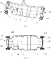
- the electric vehicle chassis comprises a frame system 2, a steering motor damping system 13 mounted on the frame system 2, a wheel system 12 connected with the steering motor damping system 13, a steering system 3 mounted on the frame system 2 and a braking system 14 mounted on the frame system 2.
- the wheel system 12 comprises a left front wheel 121 using a hub motor, a left rear wheel 123 using a hub motor, a right front wheel 122 using a hub motor, and a right rear wheel 124 using a hub motor.
- the steering motor damping system 13 comprises a left front steering damping motor 131, a right front steering damping motor 133, a left rear steering damping motor 135 and a right rear steering damping motor 137; the left front steering damping motor 131 and the right front steering damping motor 133 are respectively disposed on a left side and a right side of a front end of the frame system 2, the left rear steering damping motor 135 and the right rear steering damping motor 137 are respectively disposed on the left side and the right side of a rear end of the frame system 2.
- the left front wheel 121 is connected with the left front steering damping motor 131
- the right front wheel 122 is connected with the right front steering damping motor 133
- the left rear wheel 123 is connected with the left rear steering damping motor 13
- the right rear wheel 124 is connected with the right rear steering damping motor 137.
- the left front wheel 121, right front wheel 122, left rear wheel 123 and right rear wheel 124 each of which comprises a hub motor are used, that is the wheels are driven by the hub motors for driving, which can omit a traditional mechanical transmission system, so as to simplify the structure of the chassis, reduce the weight of the chassis, and also reduce the mechanical transmission loss, thereby improving the power utilization efficiency.
- the left front steering damping motor 131, right front steering damping motor 133, left rear steering damping motor 135 and right rear steering damping motor 137 are used to respectively adjust the steering of the left front wheel 121, right front wheel 122, left rear wheel 123 and right rear wheel 124, to adjust the rotation of each wheel.
- the hub motors may be the existing hub motors such as the hub motor disposed by the application with the publication number WO 2013107040A1 .
- the frame system 2 comprises two multi-cavity box stringers 21 spaced and symmetrically placed and made of aluminum alloy and a multi-cavity beam assembly 22 made of aluminum alloy and connected between the two multi-cavity box stringers 21.
- an inner of the multi-cavity box stringer 21 is provided with a plurality of independent cavities 213
- the multi-cavity beam assembly 22 comprises a plurality of beams each of which the inner is provided with a plurality of independent cavities
- the cross-section of the multi-cavity box stringer 21 and the respective beam may be a rectangle, a circle or a polygon and so on.
- the multi-cavity box stringer 21 and the multi-cavity beam assembly 22 together form a support structure for the electric vehicle body, to support the vehicle body, and the plurality of independent cavities inside the multi-cavity box stringer 21 and the multi-cavity beam assembly 22 may not only reduce the overall weight of the frame, but also be used as cable channels, exhausting pipes or oil pipelines of the electric vehicle and so on.
- the frame system 2 of the present invention further comprises a middle fixing frame 25 provided in the middle of the multi-cavity box stringer 25 and configured to fix a middle column of the electric vehicle.
- the number of the middle fixing frame 25 is two and the two middle fixing frames 25 are respectively provided in the middle of the two multi-cavity box stringers 21.
- the frame system 2 of the present invention only comprises the middle frame, and isn't provided with a fixing frame configured to fix a front column and the fixing frame configured to fix a rear column, and thus has a simpler structure than the structure of the frame of the conventional electric vehicle.
- the multi-cavity box stringer 21 comprises a middle portion 211 and curved portions 212 disposed on both ends of the middle portion 211, middle portion 211 can be smooth such that the electric vehicle body is stable, thereby providing a comfortable driving environment.
- the middle portion 211 may also have an arc shape with a convex in the middle to make the vehicle body more beautiful, and make the traversability of the vehicle better.
- the middle portion 211 may have other shapes.
- the curved portion 212 are curved upward from the middle portion 211 toward positions diagonally above two opposite inner sides of the two multi-cavity box stringers 21 to facilitate mounting and accommodating the wheels.
- the frame system of the present invention uses multi-cavity box stringers 21 and multi-cavity box beams which are made of aluminum alloy, which not only form the support structure for supporting the body of the electric vehicle and but also reduce the overall weight of the frame, and have simple structure and is easy to process molding, thereby greatly simplifying the production process and reducing production costs; further, since the multi-cavity box stringer 21 and the perspective beams have a plurality of independent cavities which may be used as cable channels, exhausting pipes or oil pipelines of the electric vehicle and so on, such that it doesn't need to specially provide a variety of channels such as cable channels, thereby simplifying the overall structure of the electric vehicle, simplifying the assembly of the electric vehicle, and also reducing the production costs.
- the beams comprises a front beam 221 disposed on the front ends of the two multi-cavity box stringers 21, a rear beam 222 disposed on the rear ends of the two multi-cavity box stringers 21, middle beams 223 and combined beams 224 all of which are disposed on the middle of the two multi-cavity box stringers 21. That is the middle beams 223 and combined beams 224 are connected to the middle portion 21 of the multi-cavity box stringers 21, the front beam 221 and the rear beam 222 are respectively connected to the curved portions at two ends of the multi-cavity box stringers 21, each beam is disposed between the two multi-cavity box stringers 21 to form a main bearing structure of the trapezoid shaped frame system 2.
- the middle beams 223 is two and the two middle beams 223 are spaced
- the number of the combined beams 224 is two and the two combined beams 224 are spaced.
- the middle beams 223 and the combined beams 224 may be positioned on the portions where the front seats and the rear seats are mounted in the electric vehicle, thereby supporting the seats stably.
- the left front steering damping motor 131 and the right front steering damping motor 133 are mounted on opposite ends of the front beam 221
- the left rear steering damping motor 135 and the right rear steering damping motor 137 are mounted on the opposite ends of the rear beam 222.
- the front beam 221 and the rear beam 222 may be provided with multi-cavity structure, that is the inner of the front beam 221 and the rear beam 222 is provided with a plurality of independent cavities, as shown in FIGS. 7 and 8 , the cross-section views of the front beam 221 and the rear beam 222 are respectively shown, and outer walls of the front beam 221 and the rear beam 222 may be provided with mounting slots or mounting holes or the like for mounting other parts.
- first reinforcing rods 225 may be provided between the two middle beams 223 to strengthen the beams 223 and the overall stability of the frame system 2, the first reinforcing rod 225 may also be formed with a multi-cavity structure.
- the middle beam 223 comprises a base portion 2231 with the cross-section of inverted " ⁇ " shape, a rectangular portion 2232 provided on the base portion2231 and integrally with the base portion 2231; the rectangular portion 2232 comprises a plurality of independent cavities.
- the cavities inside the base portion 2231 and the rectangular portion 2232 may be used as cable channels, ventilation pipes, oil pipelines, etc., to let the attachments of the electric vehicle or the like pass through, thus enhancing space utilization, and simplifying the overall structure of the electric vehicle.
- the inner of the middle beam 223 is provided with eight independent cavities, cross section of the cavity may has the shape of rectangular, T-shape or circular shape. Of course, the number and cross section of the cavities is not limited.
- the combined beams 224 are respectively formed by stacking two middle beams 223, the stacking manner is that the two rectangle portions of the middle beams 223 of two middle beams 223 are oppositely dispose, that is the combined beams 224 are axisymmetric, such that the inner of the combined beams 224 also has a plurality of independent cavities which also can be used as cable channels, ventilation pipes, ventilation pipes, oil pipelines and the like.
- the middle fixing frame 25 comprises a U-shaped base portion 251, two arcuate portions 252 provided on both ends of the U-shaped base portion 251, the two arcuate portions 252 are bent outwardly, and the two arcuate portions 252 are connected to the multi-cavity box stringers 21, the middle fixing frame 25 is configured to fix the middle column of the electric vehicle, the U-shaped base portion is provided with a rib 253 in the middle, for strengthening the strength and structural stability of the intermediate fixing frame 25.
- the frame system 2 of the present invention only comprises the middle frame, and isn't provided with a fixing frame configured to fix a front column and the fixing frame configured to fix a rear column, and thus has a simpler structure and is easy to assemble.
- the electric vehicle chassis also comprises a front anti-collision system 41 provided at the front end of the multi-cavity box stringer 21, the front anti-collision system 41 comprises a front crossbar 411 connected with the front beam 221, a front bumper 412 with two ends respectively connected to the front crossbar 411 and the front beam 221, and the front bumper 412 is curved, the front bumper 412 is perpendicular to the front beam 221 and the front crossbar 411, the front bumper 412 is protruded outwardly with respective to the front crossbar 411, such that the front bumper 412 is firstly hit by the outer force upon collision.
- the front anti-collision system 41 comprises a front crossbar 411 connected with the front beam 221, a front bumper 412 with two ends respectively connected to the front crossbar 411 and the front beam 221, and the front bumper 412 is curved, the front bumper 412 is perpendicular to the front beam 221 and the front crossbar 411, the front bumper 412 is protruded outwardly with respective
- the front bumper 412 can also be arranged in a manner of a multi-cavity rod, thereby enhancing the buffer and anti-collision capacity thereof.
- opposite inner sides of the front bumper 412 are provided with front damping cushions (not shown). Arranging the front damping cushions increases the anti-collision capacity of the chassis; the front damping cushion may be provided a power battery at the back to protect the power battery through the front damping cushion.
- the ends of the front bumper 412 is connected to the front beam 221 through a shock-absorbing ring a to further enhance the anti-collision capacity of the front bumper 412, at least one first lever 413 is provided between the front crossbeam 411 and the middle beam 223.
- the number of the first lever 413 is two, the first lever 413 is provided a first column 414 to enhance structure connection strength.
- the first lever 413 may formed by two half levers 4132, the two levers may be connected through a shock-absorbing gel b, to enhance anti-collision capacity thereof.
- the electric vehicle chassis also comprises a rear anti-collision system 42 provided at the rear end of the multi-cavity box stringer 21, the rear anti-collision system 42 comprises a rear crossbar 421 connected with the rear beam 222, a rear bumper 422 with two ends respectively connected to the rear crossbar 421 and the rear beam 222, and the rear bumper 422 is curved, the rear bumper 422 is perpendicular to the rear beam 222 and the rear crossbar 421, the rear bumper 422 is protruded outwardly with respective to the rear crossbar 421, such that the rear bumper 422 is firstly hit by the outer force upon collision.
- the rear anti-collision system 42 comprises a rear crossbar 421 connected with the rear beam 222, a rear bumper 422 with two ends respectively connected to the rear crossbar 421 and the rear beam 222, and the rear bumper 422 is curved, the rear bumper 422 is perpendicular to the rear beam 222 and the rear crossbar 421, the rear bumper 422 is protruded outwardly with
- the rear bumper 422 can also be arranged in a manner of a multi-cavity rod, thereby enhancing the buffer and anti-collision capacity thereof.
- opposite inner sides of the rear bumper 422 are provided with rear damping cushions (not shown). Arranging the rear damping cushions increase the anti-collision capacity of the chassis; the rear damping cushion may be provided a power battery at the front to protect the power battery through the rear damping cushion.
- the present invention may use four groups of power batteries, as one group of the power batteries does not fail, the vehicle can travel as usual, thereby improving the reliability of the battery module, and such that the fault tolerance of the vehicle power failure mode is greatly improved.
- the front bumper 412 and the rear bumper 422 of the present invention may be arranged within a vehicle body covering member, in order to ensure vehicle appearance, prevent the power batteries, the front damping cushions or the rear damping cushions from exposing, to play the role of protecting the power batteries, the front damping cushions and the rear damping cushions and the like.
- the cross section views of the front bumper 412 and the rear bumper 422 are shown, that is the inners of the front bumper 412 and the rear bumper 422 each have six independent cavities, the cross section of the cavity may have the shape of circle, polygon or the like; further, the first lever 413 can also be formed with the multi-cavity structure, the cross section of the first lever 413 may have the same shape as the front bumper 412 and the rear bumper 422.
- the ends of the rear bumper 422 is connected to the rear beam 222 through the shock-absorbing ring a to further enhance the anti-collision capacity of the rear bumper 422, at least one second lever 423 is provided between the rear crossbeam 241 and the middle beam 224.
- the number of the second lever 423 is two, the second lever 423 is provided with a second column 424 to enhance structure connection strength.
- the second lever 423 may formed by two half levers 4232, the two levers may be connected through the shock-absorbing gel b, to enhance anti-collision capacity thereof.
- the second lever 423 be formed with the multi-cavity structure, the cross section of the second lever 423 may have the same shape as the front bumper 412 and the rear bumper 422.
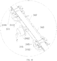
- the steering system 3 configured to control the steering of the left front wheel 121 and right front wheel 122 of the vehicle, comprises: a steering wheel 31, a steering transmission device 32 configured to transmit a turning angle of the steering wheel 31, a left turntable 331 configured to adjust a turning angle of the left front wheel 121, a right turntable 332 configured to adjust the turning angle of the right front wheel 122, and a steering device 34 configured to control the turning angles of the left turntable 331 and the right turntable 332; the left turntable 331 is connected to the left front steering damping motor 131, and the right turntable 332 is connected to the front right steering damping motor 133.
- the left turntable 331 is mounted in the left front steering damping motor 131
- the right turntable 332 is mounted in the front right steering damping motor 132.
- the steering wheel 31 is connected to one end of the steering transmission device 32, the other end of the steering transmission device 32 is connected to the steering device 34, the left turntable 331 and the right turntable 332 are respectively disposed on both sides of the steering device 34.
- the steering device 34 comprises a left steel wire rope 341, a right steel wire rope 342, and a synchronous belt 343 driven by the steering transmission device 32 to rotate, two ends of the left steel wire rope 341 are respectively wound on the left turntable 331 and the synchronous belt 343, and two ends of the right steel wire rope 342 are respectively wound on the right turntable 332 and the synchronous belt 343.
- the turning angle of the steering wheel 31 is transferred to the synchronous belt 343 through the steering transmission device 32, the synchronous belt 343 drives the left steel wire rope 341 and the right steel wire rope 342 at the same time, the left steel wire rope 341 and the right steel wire rope 342 respectively adjust the turning angle of the left front wheel 121 and the right front wheel 122.
- the steering device 34 is mounted in the front beam 221, to be protected by the steering device 34. In other embodiments, the steering device 34 may be mounted outside of the front beam.
- the synchronous belt 343 cooperates with the steering transmission device 32, and accurately drives the left turntable 331 and the right turntable 332 through the steel wires (the left steel wire rope 341 and the right steel wire rope 342 respective) and the winding manner thereof, and the turning angles of the left front wheel 121 and the right front wheel 122 are accurately controlled through the left turntable 331 and the right turntable 33.
- the present invention is also the same as the conventional steering system 3, it is possible to implement the reverse rotation.
- the present invention has simple structure, low manufacturing difficulty, low manufacturing cost, high accuracy, and is convenient for the assembly of the vehicle and wheel (hub) thereof, such that the present invention is particularly suitable for electric vehicles.
- the left synchronous belt locking member 344 and the right synchronous belt locking member 345 respectively clamp the left steel wire rope 341 and the right steel wire rope 342 on the synchronous belt 343, such that the steering may be operated the same as the conventional vehicle in the present invention, the steering wheel 31 is rotated, the steel wire rope is driven by the synchronous belt 343, to accurately control the steering of the wheel indirectly.
- the driver operates the control device on the steering wheel 31, such that the left synchronous belt locking member 344 and the right synchronous belt locking member 345 respectively release the left steel wire rope 341 and the right steel wire rope 342 from the synchronous belt 343, at this time the steel wire ropes are not driven by the synchronous belt 343, then the control device processes control through the program, so that the left front wheel 121 and the right front wheel 122 are expanded outward, and eventually forms an angle of 180 °, that is, the left front wheel 121 and the right front wheel 122 are in a straight line.
- this traveling way is particularly suitable for parking, especially for narrow parking position.
- the left front wheel 121 and the right front wheel 122 is returned to their original positions through the control device, the left synchronous belt locking member 344 and the right synchronous belt locking member 345 respectively clamp the steel wire ropes again, so that the driving can be returned to routine status.
- the left synchronous belt locking member 344 comprises a left clamping block 3441 capable of clamping the left steel wire rope 3431 on the synchronous belt 343 and a left electromagnet 3442 configured to control a clamp state and an unclamp state of the left clamping block 3441, the left electromagnet 3442 is provided on the left clamping block 3441;
- the right synchronous belt locking member 345 comprises a right clamping block 3451 capable of clamping the right steel wire rope 342 on the synchronous belt 343 and a right electromagnet 3452 configured to control the clamp state and the unclamp state of the right clamping block 3451, the right electromagnet 3452 is provided on the right clamping block 3451.
- the clamping block cooperates with the electromagnetic to clamp and unclamp the steel wire ropes, the implementation method is simple and is easy to implement.
- the steering device 34 also comprises a middle locking member 346 capable of simultaneously control distances of the left synchronous belt locking member 344 and the right synchronous belt locking member 345, the middle locking member 346 is disposed between the left synchronous belt locking member 344 and the right synchronous belt locking member 345, the left synchronous belt locking member 344 and the right synchronous belt locking member 345 are connected to the middle locking member 346 through a middle steel wire rope 347.
- the steering transmission device 32 comprises a upper transmission shaft 321 and a lower transmission shaft 322, an upper end of the upper transmission shaft 321 is connected to the steering wheel 31, a lower end of the upper transmission shaft 321 is connected to the upper end of the lower transmission shaft 322, and the lower end of the lower transmission shaft 322 is cooperatively connected to the synchronous belt 343.
- the steering transmission device 32 of the present invention may be designed with reference to the existing steering transmission device, as long as the turning angle of the steering wheel may be transferred.
- control device 311 configured for overall is provided on the steering wheel 31, the control device 311 comprises a key 3111 and a display screen 3112.
- the control device may be specifically implemented a structural design and a control program design according to requirements, but is not limited to the form shown in the drawings, and therefore is not described in detail in this embodiment.
Landscapes
- Engineering & Computer Science (AREA)
- Chemical & Material Sciences (AREA)
- Combustion & Propulsion (AREA)
- Transportation (AREA)
- Mechanical Engineering (AREA)
- Architecture (AREA)
- Structural Engineering (AREA)
- Body Structure For Vehicles (AREA)
- Arrangement Or Mounting Of Propulsion Units For Vehicles (AREA)
- Steering Controls (AREA)
- Steering-Linkage Mechanisms And Four-Wheel Steering (AREA)
- Power Steering Mechanism (AREA)
Claims (13)
- Elektrofahrzeugfahrgestell, umfassend ein Rahmensystem (2), ein am Rahmensystem (2) montiertes Lenkungsmotordämpfungssystem (13), ein mit dem Lenkungsmotordämpfungssystem (13) verbundenes Radsystem (12), ein am Rahmensystem (2) montiertes Lenksystem (3) und ein am Rahmensystem (2) montiertes Bremssystem (14), wobei das Radsystem (12) ein linkes Vorderrad (121), das einen Nabenmotor verwendet, ein linkes Hinterrad (123), das einen Nabenmotor verwendet, ein rechtes Vorderrad (122), das einen Nabenmotor verwendet, und ein rechtes Hinterrad (124), das einen Nabenmotor verwendet, umfasst; wobei das Lenkungsmotordämpfungssystem (13) einen linken vorderen Lenkungsdämpfungsmotor (131), einen rechten vorderen Lenkungsdämpfungsmotor (133), einen linken hinteren Lenkungsdämpfungsmotor (135) und einen rechten hinteren Lenkungsdämpfungsmotor (137) umfasst; wobei der linke vordere Lenkungsdämpfungsmotor (131) und der rechte vordere Lenkungsdämpfungsmotor (133) auf der linken Seite bzw. der rechten Seite eines vorderen Endes des Rahmensystems (2) angeordnet sind, der linke hintere Lenkungsdämpfungsmotor (135) und der rechte hintere Lenkungsdämpfungsmotor (137) auf der linken Seite bzw. der rechten Seite eines hinteren Endes des Rahmensystems (2) angeordnet sind; wobei das linke Vorderrad (121) mit dem linken vorderen Lenkungsdämpfungsmotor (131) verbunden ist, das rechte Vorderrad (122) mit dem rechten vorderen Lenkungsdämpfungsmotor (133) verbunden ist, das linke Hinterrad (123) mit dem linken hinteren Lenkungsdämpfungsmotor (135) verbunden ist, das rechte Hinterrad (124) mit dem rechten hinteren Lenkungsdämpfungsmotor (137) verbunden ist,
dadurch gekennzeichnet, dass
das Rahmensystem (2) zwei Mehrfachhohlraumkastenlängsträger (21), die beabstandet und symmetrisch angeordnet und aus einer Aluminiumlegierung hergestellt sind, und eine Mehrfachhohlraumträgerbaugruppe (22), die aus einer Aluminiumlegierung hergestellt und zwischen den zwei Mehrfachhohlraumkastenlängsträgern (21) verbunden ist, umfasst, wobei der Mehrfachhohlraumkastenlängsträger innen mit einer Vielzahl von unabhängigen Hohlräumen versehen ist, die Mehrfachhohlraumträgerbaugruppe (22) eine Vielzahl von Trägern umfasst, die innen jeweils mit einer Vielzahl von unabhängigen Hohlräumen versehen sind, wobei der Mehrfachhohlraumkastenlängsträger einen Mittelabschnitt (211) und Krümmungsabschnitte umfasst, die an beiden Enden des Mittelabschnitts (211) angeordnet sind, wobei die Krümmungsabschnitte vom Mittelabschnitt (211) nach oben in Richtung Positionen diagonal über zwei gegenüberliegenden Innenseiten der zwei Mehrfachhohlraumkastenlängsträger (21) gekrümmt sind. - Elektrofahrzeugfahrgestell nach Anspruch 1, dadurch gekennzeichnet, dass die Träger einen vorderen Träger (221), der auf den vorderen Enden der zwei Mehrfachhohlraumkastenlängsträger (21) angeordnet ist, einen hinteren Träger, der auf den hinteren Enden der zwei Mehrfachhohlraumkastenlängsträger (21) angeordnet ist, mittlere Träger (223) und kombinierte Träger (224) aufweist, die alle auf der Mitte der zwei Mehrfachhohlraumkastenlängsträger (21) angeordnet sind, wobei die Zahl der mittleren Träger (223) zwei ist und die zwei mittleren Träger (223) beabstandet sind, die Zahl der kombinierten Träger (224) zwei ist und die zwei kombinierten Träger (224) beabstandet sind, der linke vordere Lenkungsdämpfungsmotor (131) und der rechte vordere Lenkungsdämpfungsmotor (133) auf gegenüberliegenden Enden des vorderen Trägers (221) montiert sind, der linke hintere Lenkungsdämpfungsmotor (135) und der rechte hintere Lenkungsdämpfungsmotor (137) auf gegenüberliegenden Enden des hinteren Trägers montiert sind.
- Elektromotorfahrzeugfahrgestell nach Anspruch 2, dadurch gekennzeichnet, dass das Rahmensystem (2) zusätzlich einen mittleren Befestigungsrahmen aufweist, der in der Mitte des Mehrfachhohlraumkastenlängsträgers vorgesehen ist und so konfiguriert ist, dass er eine Mittelsäule befestigt.
- Elektromotorfahrzeugfahrgestell nach Anspruch 3, dadurch gekennzeichnet, dass der mittlere Befestigungsrahmen einen U-förmigen Basisabschnitt (251), zwei bogenförmige Abschnitte aufweist, die auf beiden Enden des U-förmigen Basisabschnitts (251) vorgesehen sind, wobei die zwei bogenförmigen Abschnitte nach außen gebogen und mit dem Mehrfachhohlraumkastenlängsträger (21) verbunden sind, wobei der U-förmige Basisabschnitt (251) in der Mitte mit einer Rippe (253) versehen ist.
- Elektromotorfahrzeugfahrgestell nach einem der Ansprüche 2-4, das zusätzlich ein vorderes Antikollisionssystem (41) aufweist, das am vorderen Ende des Mehrfachhohlraumkastenlängsträgers vorgesehen ist, wobei das vordere Antikollisionssystem (41) einen mit dem vorderen Träger (221) verbundenen vorderen Querträger (411), eine vordere Stoßstange (412) mit zwei Enden aufweist, die mit dem vorderen Querträger (411) bzw. dem vorderen Träger (221) verbunden sind, wobei die vordere Stoßstange (412) gekrümmt und senkrecht zum vorderen Träger (221) und zum vorderen Querträger (411) ist, wobei die vordere Stoßstange (412) relativ zum vorderen Querträger (411) nach außen hervorsteht.
- Elektromotorfahrzeugfahrgestell nach Anspruch 5, dadurch gekennzeichnet, dass gegenüberliegende innere Seiten der vorderen Stoßstange (412) mit vorderen Dämpfungskissen versehen sind.
- Elektromotorfahrzeugfahrgestell nach Anspruch 5, dadurch gekennzeichnet, dass die Enden der vorderen Stoßstange (412) durch einen schockabsorbierenden Ring mit dem vorderen Träger (221) verbunden ist, zumindest ein erster Hebel zwischen dem vorderen Querträger und dem mittleren Träger vorgesehen ist, wobei der erste Hebel (413) mit einer ersten Säule (414) versehen ist.
- Elektromotorfahrzeugfahrgestell nach einem der Ansprüche 2-4, das zusätzlich ein hinteres Antikollisionssystem (42) aufweist, das am hinteren Ende des Mehrfachhohlraumkastenlängsträgers (21) vorgesehen ist, wobei das hintere Antikollisionssystem (42) einen mit dem hinteren Träger (222) verbundenen hinteren Querträger (421), eine hintere Stoßstange (422) mit zwei Enden aufweist, die mit dem hinteren Querträger (421) bzw. dem hinteren Träger (222) verbunden sind, wobei die hintere Stoßstange (422) gekrümmt und senkrecht zum hinteren Träger (222) und zum hinteren Querträger (421) ist, wobei die hintere Stoßstange (422) relativ zum hinteren Querträger (421) nach außen hervorsteht.
- Elektromotorfahrzeugfahrgestell nach Anspruch 8, dadurch gekennzeichnet, dass gegenüberliegende innere Seiten der hinteren Stoßstange (422) mit hinteren Dämpfungskissen versehen sind.
- Elektromotorfahrzeugfahrgestell nach Anspruch 8, wobei die Enden der hinteren Stoßstange (422) durch einen schockabsorbierenden Ring mit dem hinteren Träger (222) verbunden ist, zumindest ein zweiter Hebel (423) zwischen dem hinteren Querträger (241) und dem kombinierten Träger (224) vorgesehen ist, wobei der zweite Hebel (423) mit einer zweiten Säule (424) versehen ist.
- Elektromotorfahrzeugfahrgestell nach einem der Ansprüche 1-4, dadurch gekennzeichnet, dass das Lenksystem (3) ein Lenkrad (31), eine Lenkübertragungsvorrichtung (32), die so konfiguriert ist, dass sie einen Drehwinkel des Lenkrads (31) überträgt, eine linke Drehscheibe (331), die so konfiguriert ist, dass sie einen Drehwinkel des linken Vorderrads (121) einstellt, eine rechte Drehscheibe (332), die so konfiguriert ist, dass sie den Drehwinkel des rechten Vorderrads (122) einstellt, und eine Lenkvorrichtung (34) aufweist, die so konfiguriert ist, dass sie die Drehwinkel der linken Drehscheibe (331) und der rechten Drehscheibe (332) steuert; wobei das Lenkrad (31) mit einem Ende der Lenkübertragungsvorrichtung (32) verbunden ist, das andere Ende der Lenkübertragungsvorrichtung (32) mit der Lenkvorrichtung (34) verbunden ist, die linke Drehscheibe (331) und die rechte Drehscheibe (332) jeweils auf beiden Seiten der Lenkvorrichtung (34) angeordnet sind, die linke Drehscheibe (331) mit dem linken vorderen Lenkungsdämpfungsmotor (131) verbunden ist, und die rechte Drehscheibe (332) mit dem vorderen rechten Lenkungsdämpfungsmotor (132) verbunden ist.
- Elektromotorfahrzeugfahrgestell nach Anspruch 11, dadurch gekennzeichnet, dass die Lenkübertragungsvorrichtung eine obere Übertragungswelle und eine untere Übertragungswelle aufweist, wobei ein oberes Ende der oberen Übertragungswelle mit dem Lenkrad verbunden ist, ein unteres Ende der oberen Übertragungswelle mit dem oberen Ende der unteren Übertragungswelle verbunden ist, und das untere Ende der unteren Übertragungswelle gemeinsam mit dem Zahnriemen verbunden ist.
- Elektrofahrzeug, das ein Elektromotorfahrzeugfahrgestell nach einem der Ansprüche 1-12 aufweist.
Priority Applications (2)
| Application Number | Priority Date | Filing Date | Title |
|---|---|---|---|
| PT148878788T PT3127784T (pt) | 2014-04-01 | 2014-04-01 | Chassis de veículo elétrico e veículo elétrico utilizando o mesmo |
| PL14887878T PL3127784T3 (pl) | 2014-04-01 | 2014-04-01 | Rama pojazdu elektrycznego i wykorzystujący ją pojazd elektryczny |
Applications Claiming Priority (1)
| Application Number | Priority Date | Filing Date | Title |
|---|---|---|---|
| PCT/CN2014/074517 WO2015149269A1 (zh) | 2014-04-01 | 2014-04-01 | 电动车底盘及其电动汽车 |
Publications (3)
| Publication Number | Publication Date |
|---|---|
| EP3127784A1 EP3127784A1 (de) | 2017-02-08 |
| EP3127784A4 EP3127784A4 (de) | 2018-01-31 |
| EP3127784B1 true EP3127784B1 (de) | 2019-11-13 |
Family
ID=54239257
Family Applications (1)
| Application Number | Title | Priority Date | Filing Date |
|---|---|---|---|
| EP14887878.8A Active EP3127784B1 (de) | 2014-04-01 | 2014-04-01 | Elektrofahrzeugchassis und elektrofahrzeug damit |
Country Status (9)
| Country | Link |
|---|---|
| US (1) | US10155442B2 (de) |
| EP (1) | EP3127784B1 (de) |
| JP (1) | JP6397049B2 (de) |
| KR (1) | KR102207500B1 (de) |
| CN (1) | CN106132811B (de) |
| ES (1) | ES2770584T3 (de) |
| PL (1) | PL3127784T3 (de) |
| PT (1) | PT3127784T (de) |
| WO (1) | WO2015149269A1 (de) |
Cited By (2)
| Publication number | Priority date | Publication date | Assignee | Title |
|---|---|---|---|---|
| USD902088S1 (en) * | 2018-10-29 | 2020-11-17 | Applied Electric Vehicles Pty Ltd | Vehicle chassis |
| USD902792S1 (en) * | 2018-11-02 | 2020-11-24 | Applied Electric Vehicles Pty Ltd | Vehicle chassis |
Families Citing this family (13)
| Publication number | Priority date | Publication date | Assignee | Title |
|---|---|---|---|---|
| JP6488826B2 (ja) * | 2015-03-31 | 2019-03-27 | 株式会社デンソー | 外乱防止カバー |
| CN109204496B (zh) | 2017-06-30 | 2020-10-23 | 比亚迪股份有限公司 | 车身结构及车辆 |
| CN108128351A (zh) * | 2018-02-02 | 2018-06-08 | 河北农业大学 | 一种gps导航式电动多功能底盘 |
| CN108407898B (zh) * | 2018-05-08 | 2023-08-11 | 广州汽车集团股份有限公司 | 一种前地板笼式梁架结构 |
| CN109455226A (zh) * | 2018-11-23 | 2019-03-12 | 北京宏瑞汽车科技股份有限公司 | 一种纯电动车车架结构 |
| US11767060B2 (en) * | 2019-04-12 | 2023-09-26 | Textron Innovations Inc. | Lightweight vehicle |
| USD944684S1 (en) * | 2019-12-31 | 2022-03-01 | Ree Automotive Ltd. | Multipurpose flat chassis vehicle platform |
| US10919575B1 (en) | 2020-07-30 | 2021-02-16 | Ree Automotive Ltd | Vehicle chassis platform |
| US11260909B2 (en) * | 2020-06-03 | 2022-03-01 | Ree Automotive Ltd | Vehicle chassis platform |
| CN113682128A (zh) * | 2020-05-18 | 2021-11-23 | 大富科技(安徽)股份有限公司 | 一种电动车的底盘及其连接件 |
| USD1066152S1 (en) * | 2020-11-03 | 2025-03-11 | Applied Electric Vehicles Pty Ltd | Platform for electric vehicle |
| CN112895884A (zh) * | 2021-03-03 | 2021-06-04 | 山东科技大学 | 一种新能源6×6特种底盘车驱动结构 |
| TWD229059S (zh) * | 2023-05-04 | 2023-12-11 | 庫得科技股份有限公司 | 電動汽車底盤用大樑 |
Family Cites Families (28)
| Publication number | Priority date | Publication date | Assignee | Title |
|---|---|---|---|---|
| JPS5284649A (en) * | 1975-12-29 | 1977-07-14 | Suzuki Motor Co Ltd | Car steering apparatus |
| JPS58149239U (ja) * | 1982-04-01 | 1983-10-06 | 春日鑿泉株式会社 | 圧縮空気帯バンバ− |
| JPS6116173A (ja) * | 1984-07-02 | 1986-01-24 | アツプ−ライト・インコ−ポレ−テツド | 車両用ステアリングシステム |
| FR2710893B1 (fr) * | 1993-10-05 | 1995-11-17 | Smh Management Services Ag | Châssis pour véhicule, notamment pour véhicule automobile. |
| JPH07132852A (ja) * | 1993-11-12 | 1995-05-23 | Honda Motor Co Ltd | 電気自動車 |
| US5561902A (en) * | 1994-09-28 | 1996-10-08 | Cosma International Inc. | Method of manufacturing a ladder frame assembly for a motor vehicle |
| DE19748474C1 (de) * | 1997-11-03 | 1999-08-12 | Horst Staiger & Soehne Gmbh | Hinterachslenkvorrichtung |
| US6378637B1 (en) * | 1999-05-28 | 2002-04-30 | Honda Giken Kogyo Kabushiki Kaisha | Fuel-cell-powered electric automobile |
| JP2001063604A (ja) * | 1999-06-23 | 2001-03-13 | Komatsu Forklift Co Ltd | フォークリフトの操舵制御装置 |
| US7533747B2 (en) * | 2000-01-26 | 2009-05-19 | E-Traction Europe B.V. | Wheel provided with driving means |
| US7303211B2 (en) * | 2001-08-23 | 2007-12-04 | Gm Global Technology Operations, Inc. | Fuel cell vehicle architecture |
| US7292992B2 (en) * | 2001-08-23 | 2007-11-06 | General Motors Corporation | Methods of conducting vehicle business transactions |
| US7441615B2 (en) * | 2001-12-07 | 2008-10-28 | General Motors Corporation | Modular chassis with simplified body-attachment interface |
| US7597169B2 (en) * | 2001-12-07 | 2009-10-06 | Gm Global Technology Operations, Inc. | Wheel module |
| WO2006029415A2 (en) * | 2004-09-10 | 2006-03-16 | General Motors Corporation | Fuel cell vehicle architecture |
| CN100546843C (zh) * | 2004-10-29 | 2009-10-07 | 福特全球技术公司 | 一种用于车辆的燃料存储系统 |
| JP2007083848A (ja) * | 2005-09-21 | 2007-04-05 | Toyota Motor Corp | 車両用ステアリングシステム |
| JP4767009B2 (ja) * | 2005-12-14 | 2011-09-07 | 日立ビークルエナジー株式会社 | 組電池 |
| JP2009040316A (ja) * | 2007-08-10 | 2009-02-26 | Toyota Motor Corp | フレーム付車両の車体構造 |
| DE102008020694B4 (de) * | 2008-04-24 | 2012-11-22 | Benteler Automobiltechnik Gmbh | Kraftfahrzeugrahmen |
| JP4696291B2 (ja) * | 2009-06-04 | 2011-06-08 | 三菱自動車工業株式会社 | 二次電池異常検出装置 |
| CN201484168U (zh) | 2009-08-21 | 2010-05-26 | 山东大学 | 独立驱动、转向、悬挂和制动的一体化车轮总成 |
| CN201694244U (zh) * | 2010-03-29 | 2011-01-05 | 裘宇朝 | 一种纯电动汽车的底盘结构 |
| US8710800B2 (en) * | 2011-07-26 | 2014-04-29 | GM Global Technology Operations LLC | Vehicle battery with cell balancing current paths and method of charging the same |
| JP2013112168A (ja) * | 2011-11-29 | 2013-06-10 | Ntn Corp | 電気自動車の車体構造 |
| CN202966436U (zh) * | 2012-12-10 | 2013-06-05 | 湖北万世达汽车部件有限公司 | 一种承载式电动微型卡车车架总成 |
| CN203094172U (zh) * | 2012-12-24 | 2013-07-31 | 中国科学院深圳先进技术研究院 | 一种独立转向与驱动电动汽车的线控转向装置及其悬架系统 |
| JP6167717B2 (ja) * | 2013-07-19 | 2017-07-26 | 日産自動車株式会社 | サスペンション装置 |
-
2014
- 2014-04-01 KR KR1020167028264A patent/KR102207500B1/ko not_active Expired - Fee Related
- 2014-04-01 ES ES14887878T patent/ES2770584T3/es active Active
- 2014-04-01 CN CN201480076823.0A patent/CN106132811B/zh not_active Expired - Fee Related
- 2014-04-01 WO PCT/CN2014/074517 patent/WO2015149269A1/zh not_active Ceased
- 2014-04-01 US US15/300,536 patent/US10155442B2/en active Active
- 2014-04-01 JP JP2016560757A patent/JP6397049B2/ja not_active Expired - Fee Related
- 2014-04-01 PT PT148878788T patent/PT3127784T/pt unknown
- 2014-04-01 PL PL14887878T patent/PL3127784T3/pl unknown
- 2014-04-01 EP EP14887878.8A patent/EP3127784B1/de active Active
Non-Patent Citations (1)
| Title |
|---|
| None * |
Cited By (2)
| Publication number | Priority date | Publication date | Assignee | Title |
|---|---|---|---|---|
| USD902088S1 (en) * | 2018-10-29 | 2020-11-17 | Applied Electric Vehicles Pty Ltd | Vehicle chassis |
| USD902792S1 (en) * | 2018-11-02 | 2020-11-24 | Applied Electric Vehicles Pty Ltd | Vehicle chassis |
Also Published As
| Publication number | Publication date |
|---|---|
| EP3127784A1 (de) | 2017-02-08 |
| KR102207500B1 (ko) | 2021-01-26 |
| JP6397049B2 (ja) | 2018-09-26 |
| CN106132811A (zh) | 2016-11-16 |
| WO2015149269A1 (zh) | 2015-10-08 |
| US20170151870A1 (en) | 2017-06-01 |
| US10155442B2 (en) | 2018-12-18 |
| PL3127784T3 (pl) | 2020-06-01 |
| JP2017513753A (ja) | 2017-06-01 |
| ES2770584T3 (es) | 2020-07-02 |
| PT3127784T (pt) | 2020-02-21 |
| EP3127784A4 (de) | 2018-01-31 |
| CN106132811B (zh) | 2017-12-22 |
| KR20160140721A (ko) | 2016-12-07 |
Similar Documents
| Publication | Publication Date | Title |
|---|---|---|
| EP3127784B1 (de) | Elektrofahrzeugchassis und elektrofahrzeug damit | |
| CN112292278B (zh) | 车辆用电池组支撑装置 | |
| JP6421766B2 (ja) | フレーム車の骨格構造 | |
| US9505442B2 (en) | Energy absorbing rocker assembly | |
| JP5696793B2 (ja) | 車体構造 | |
| US20150375783A1 (en) | Drive Device for Electric Vehicle | |
| JP6268280B2 (ja) | 車両 | |
| KR20160140738A (ko) | 전기 자동차 프레임 시스템 | |
| CN111806575B (zh) | 新能源汽车的c环结构 | |
| KR20200063396A (ko) | 배터리부와 모터 및 프레임이 일체화된 통합형 편평형차대 | |
| CN104787123A (zh) | 一种换电式电动汽车车身前地板下横梁连接结构 | |
| JP2017197018A (ja) | 車両のバッテリ搭載構造 | |
| KR101165734B1 (ko) | 버스용 복합소재 플로어 | |
| JP5611731B2 (ja) | インホイールモータ型電気自動車 | |
| CN105818664A (zh) | 包括框架梁嵌入件的蓄电池阵列框架 | |
| CN219948349U (zh) | 车身组件及车辆 | |
| CN112477985B (zh) | 用于跨车辆载荷路径的车辆结构 | |
| CN204713207U (zh) | 用于车辆的车架及具有该车架的车辆 | |
| KR101304803B1 (ko) | 전기 자동차 차체 | |
| KR20210103624A (ko) | 고전압배터리를 탑재하는 차량의 차체 | |
| US20240208593A1 (en) | Folding inflatable vehicle | |
| JP2022187738A (ja) | 電動車両 | |
| CN119998153A (zh) | 一种滑板底盘及车辆 | |
| CN102358250A (zh) | 一种电动汽车前舱元件固定结构 | |
| CN202879612U (zh) | 一种后地板分块结构 |
Legal Events
| Date | Code | Title | Description |
|---|---|---|---|
| STAA | Information on the status of an ep patent application or granted ep patent |
Free format text: STATUS: THE INTERNATIONAL PUBLICATION HAS BEEN MADE |
|
| PUAI | Public reference made under article 153(3) epc to a published international application that has entered the european phase |
Free format text: ORIGINAL CODE: 0009012 |
|
| STAA | Information on the status of an ep patent application or granted ep patent |
Free format text: STATUS: REQUEST FOR EXAMINATION WAS MADE |
|
| 17P | Request for examination filed |
Effective date: 20161025 |
|
| AK | Designated contracting states |
Kind code of ref document: A1 Designated state(s): AL AT BE BG CH CY CZ DE DK EE ES FI FR GB GR HR HU IE IS IT LI LT LU LV MC MK MT NL NO PL PT RO RS SE SI SK SM TR |
|
| AX | Request for extension of the european patent |
Extension state: BA ME |
|
| DAX | Request for extension of the european patent (deleted) | ||
| A4 | Supplementary search report drawn up and despatched |
Effective date: 20180105 |
|
| RIC1 | Information provided on ipc code assigned before grant |
Ipc: B62D 25/02 20060101ALI20171222BHEP Ipc: B62D 21/02 20060101AFI20171222BHEP Ipc: B62D 25/20 20060101ALI20171222BHEP Ipc: B62D 5/04 20060101ALI20171222BHEP Ipc: B60K 1/02 20060101ALI20171222BHEP Ipc: B62D 23/00 20060101ALI20171222BHEP Ipc: B60K 17/356 20060101ALI20171222BHEP Ipc: B62D 21/15 20060101ALI20171222BHEP Ipc: B62D 29/00 20060101ALI20171222BHEP Ipc: B62D 25/04 20060101ALI20171222BHEP Ipc: B60K 17/14 20060101ALI20171222BHEP |
|
| RAP1 | Party data changed (applicant data changed or rights of an application transferred) |
Owner name: GUANGDONG HUA'CHAN RESEARCH INSTITUTE OF INTELLIGE |
|
| GRAP | Despatch of communication of intention to grant a patent |
Free format text: ORIGINAL CODE: EPIDOSNIGR1 |
|
| STAA | Information on the status of an ep patent application or granted ep patent |
Free format text: STATUS: GRANT OF PATENT IS INTENDED |
|
| INTG | Intention to grant announced |
Effective date: 20190619 |
|
| GRAS | Grant fee paid |
Free format text: ORIGINAL CODE: EPIDOSNIGR3 |
|
| GRAA | (expected) grant |
Free format text: ORIGINAL CODE: 0009210 |
|
| STAA | Information on the status of an ep patent application or granted ep patent |
Free format text: STATUS: THE PATENT HAS BEEN GRANTED |
|
| AK | Designated contracting states |
Kind code of ref document: B1 Designated state(s): AL AT BE BG CH CY CZ DE DK EE ES FI FR GB GR HR HU IE IS IT LI LT LU LV MC MK MT NL NO PL PT RO RS SE SI SK SM TR |
|
| REG | Reference to a national code |
Ref country code: CH Ref legal event code: EP Ref country code: AT Ref legal event code: REF Ref document number: 1201379 Country of ref document: AT Kind code of ref document: T Effective date: 20191115 |
|
| REG | Reference to a national code |
Ref country code: DE Ref legal event code: R096 Ref document number: 602014056956 Country of ref document: DE |
|
| REG | Reference to a national code |
Ref country code: IE Ref legal event code: FG4D |
|
| REG | Reference to a national code |
Ref country code: CH Ref legal event code: NV Representative=s name: DENNEMEYER AG, CH |
|
| REG | Reference to a national code |
Ref country code: NO Ref legal event code: T2 Effective date: 20191113 |
|
| REG | Reference to a national code |
Ref country code: PT Ref legal event code: SC4A Ref document number: 3127784 Country of ref document: PT Date of ref document: 20200221 Kind code of ref document: T Free format text: AVAILABILITY OF NATIONAL TRANSLATION Effective date: 20200212 |
|
| REG | Reference to a national code |
Ref country code: LT Ref legal event code: MG4D |
|
| PG25 | Lapsed in a contracting state [announced via postgrant information from national office to epo] |
Ref country code: LT Free format text: LAPSE BECAUSE OF FAILURE TO SUBMIT A TRANSLATION OF THE DESCRIPTION OR TO PAY THE FEE WITHIN THE PRESCRIBED TIME-LIMIT Effective date: 20191113 Ref country code: FI Free format text: LAPSE BECAUSE OF FAILURE TO SUBMIT A TRANSLATION OF THE DESCRIPTION OR TO PAY THE FEE WITHIN THE PRESCRIBED TIME-LIMIT Effective date: 20191113 Ref country code: BG Free format text: LAPSE BECAUSE OF FAILURE TO SUBMIT A TRANSLATION OF THE DESCRIPTION OR TO PAY THE FEE WITHIN THE PRESCRIBED TIME-LIMIT Effective date: 20200213 Ref country code: GR Free format text: LAPSE BECAUSE OF FAILURE TO SUBMIT A TRANSLATION OF THE DESCRIPTION OR TO PAY THE FEE WITHIN THE PRESCRIBED TIME-LIMIT Effective date: 20200214 Ref country code: SE Free format text: LAPSE BECAUSE OF FAILURE TO SUBMIT A TRANSLATION OF THE DESCRIPTION OR TO PAY THE FEE WITHIN THE PRESCRIBED TIME-LIMIT Effective date: 20191113 Ref country code: LV Free format text: LAPSE BECAUSE OF FAILURE TO SUBMIT A TRANSLATION OF THE DESCRIPTION OR TO PAY THE FEE WITHIN THE PRESCRIBED TIME-LIMIT Effective date: 20191113 |
|
| REG | Reference to a national code |
Ref country code: NL Ref legal event code: FP |
|
| PG25 | Lapsed in a contracting state [announced via postgrant information from national office to epo] |
Ref country code: RS Free format text: LAPSE BECAUSE OF FAILURE TO SUBMIT A TRANSLATION OF THE DESCRIPTION OR TO PAY THE FEE WITHIN THE PRESCRIBED TIME-LIMIT Effective date: 20191113 Ref country code: HR Free format text: LAPSE BECAUSE OF FAILURE TO SUBMIT A TRANSLATION OF THE DESCRIPTION OR TO PAY THE FEE WITHIN THE PRESCRIBED TIME-LIMIT Effective date: 20191113 Ref country code: IS Free format text: LAPSE BECAUSE OF FAILURE TO SUBMIT A TRANSLATION OF THE DESCRIPTION OR TO PAY THE FEE WITHIN THE PRESCRIBED TIME-LIMIT Effective date: 20200313 |
|
| PG25 | Lapsed in a contracting state [announced via postgrant information from national office to epo] |
Ref country code: AL Free format text: LAPSE BECAUSE OF FAILURE TO SUBMIT A TRANSLATION OF THE DESCRIPTION OR TO PAY THE FEE WITHIN THE PRESCRIBED TIME-LIMIT Effective date: 20191113 |
|
| REG | Reference to a national code |
Ref country code: ES Ref legal event code: FG2A Ref document number: 2770584 Country of ref document: ES Kind code of ref document: T3 Effective date: 20200702 |
|
| PG25 | Lapsed in a contracting state [announced via postgrant information from national office to epo] |
Ref country code: RO Free format text: LAPSE BECAUSE OF FAILURE TO SUBMIT A TRANSLATION OF THE DESCRIPTION OR TO PAY THE FEE WITHIN THE PRESCRIBED TIME-LIMIT Effective date: 20191113 Ref country code: DK Free format text: LAPSE BECAUSE OF FAILURE TO SUBMIT A TRANSLATION OF THE DESCRIPTION OR TO PAY THE FEE WITHIN THE PRESCRIBED TIME-LIMIT Effective date: 20191113 Ref country code: EE Free format text: LAPSE BECAUSE OF FAILURE TO SUBMIT A TRANSLATION OF THE DESCRIPTION OR TO PAY THE FEE WITHIN THE PRESCRIBED TIME-LIMIT Effective date: 20191113 |
|
| REG | Reference to a national code |
Ref country code: DE Ref legal event code: R097 Ref document number: 602014056956 Country of ref document: DE |
|
| REG | Reference to a national code |
Ref country code: AT Ref legal event code: MK05 Ref document number: 1201379 Country of ref document: AT Kind code of ref document: T Effective date: 20191113 |
|
| PG25 | Lapsed in a contracting state [announced via postgrant information from national office to epo] |
Ref country code: SK Free format text: LAPSE BECAUSE OF FAILURE TO SUBMIT A TRANSLATION OF THE DESCRIPTION OR TO PAY THE FEE WITHIN THE PRESCRIBED TIME-LIMIT Effective date: 20191113 Ref country code: SM Free format text: LAPSE BECAUSE OF FAILURE TO SUBMIT A TRANSLATION OF THE DESCRIPTION OR TO PAY THE FEE WITHIN THE PRESCRIBED TIME-LIMIT Effective date: 20191113 |
|
| PLBE | No opposition filed within time limit |
Free format text: ORIGINAL CODE: 0009261 |
|
| STAA | Information on the status of an ep patent application or granted ep patent |
Free format text: STATUS: NO OPPOSITION FILED WITHIN TIME LIMIT |
|
| 26N | No opposition filed |
Effective date: 20200814 |
|
| PG25 | Lapsed in a contracting state [announced via postgrant information from national office to epo] |
Ref country code: MC Free format text: LAPSE BECAUSE OF FAILURE TO SUBMIT A TRANSLATION OF THE DESCRIPTION OR TO PAY THE FEE WITHIN THE PRESCRIBED TIME-LIMIT Effective date: 20191113 Ref country code: SI Free format text: LAPSE BECAUSE OF FAILURE TO SUBMIT A TRANSLATION OF THE DESCRIPTION OR TO PAY THE FEE WITHIN THE PRESCRIBED TIME-LIMIT Effective date: 20191113 Ref country code: AT Free format text: LAPSE BECAUSE OF FAILURE TO SUBMIT A TRANSLATION OF THE DESCRIPTION OR TO PAY THE FEE WITHIN THE PRESCRIBED TIME-LIMIT Effective date: 20191113 |
|
| PG25 | Lapsed in a contracting state [announced via postgrant information from national office to epo] |
Ref country code: LU Free format text: LAPSE BECAUSE OF NON-PAYMENT OF DUE FEES Effective date: 20200401 Ref country code: IT Free format text: LAPSE BECAUSE OF FAILURE TO SUBMIT A TRANSLATION OF THE DESCRIPTION OR TO PAY THE FEE WITHIN THE PRESCRIBED TIME-LIMIT Effective date: 20191113 |
|
| REG | Reference to a national code |
Ref country code: BE Ref legal event code: MM Effective date: 20200430 |
|
| PG25 | Lapsed in a contracting state [announced via postgrant information from national office to epo] |
Ref country code: BE Free format text: LAPSE BECAUSE OF NON-PAYMENT OF DUE FEES Effective date: 20200430 |
|
| PG25 | Lapsed in a contracting state [announced via postgrant information from national office to epo] |
Ref country code: IE Free format text: LAPSE BECAUSE OF NON-PAYMENT OF DUE FEES Effective date: 20200401 |
|
| PGFP | Annual fee paid to national office [announced via postgrant information from national office to epo] |
Ref country code: CZ Payment date: 20210401 Year of fee payment: 8 Ref country code: NO Payment date: 20210422 Year of fee payment: 8 Ref country code: PT Payment date: 20210401 Year of fee payment: 8 |
|
| PGFP | Annual fee paid to national office [announced via postgrant information from national office to epo] |
Ref country code: ES Payment date: 20210621 Year of fee payment: 8 Ref country code: PL Payment date: 20210331 Year of fee payment: 8 |
|
| PGFP | Annual fee paid to national office [announced via postgrant information from national office to epo] |
Ref country code: NL Payment date: 20210420 Year of fee payment: 8 |
|
| PG25 | Lapsed in a contracting state [announced via postgrant information from national office to epo] |
Ref country code: TR Free format text: LAPSE BECAUSE OF FAILURE TO SUBMIT A TRANSLATION OF THE DESCRIPTION OR TO PAY THE FEE WITHIN THE PRESCRIBED TIME-LIMIT Effective date: 20191113 Ref country code: MT Free format text: LAPSE BECAUSE OF FAILURE TO SUBMIT A TRANSLATION OF THE DESCRIPTION OR TO PAY THE FEE WITHIN THE PRESCRIBED TIME-LIMIT Effective date: 20191113 Ref country code: CY Free format text: LAPSE BECAUSE OF FAILURE TO SUBMIT A TRANSLATION OF THE DESCRIPTION OR TO PAY THE FEE WITHIN THE PRESCRIBED TIME-LIMIT Effective date: 20191113 |
|
| PG25 | Lapsed in a contracting state [announced via postgrant information from national office to epo] |
Ref country code: MK Free format text: LAPSE BECAUSE OF FAILURE TO SUBMIT A TRANSLATION OF THE DESCRIPTION OR TO PAY THE FEE WITHIN THE PRESCRIBED TIME-LIMIT Effective date: 20191113 |
|
| PG25 | Lapsed in a contracting state [announced via postgrant information from national office to epo] |
Ref country code: CZ Free format text: LAPSE BECAUSE OF NON-PAYMENT OF DUE FEES Effective date: 20220401 |
|
| REG | Reference to a national code |
Ref country code: NO Ref legal event code: MMEP |
|
| REG | Reference to a national code |
Ref country code: NL Ref legal event code: MM Effective date: 20220501 |
|
| PG25 | Lapsed in a contracting state [announced via postgrant information from national office to epo] |
Ref country code: PT Free format text: LAPSE BECAUSE OF NON-PAYMENT OF DUE FEES Effective date: 20221003 Ref country code: NO Free format text: LAPSE BECAUSE OF NON-PAYMENT OF DUE FEES Effective date: 20220430 Ref country code: NL Free format text: LAPSE BECAUSE OF NON-PAYMENT OF DUE FEES Effective date: 20220501 |
|
| REG | Reference to a national code |
Ref country code: ES Ref legal event code: FD2A Effective date: 20230605 |
|
| PG25 | Lapsed in a contracting state [announced via postgrant information from national office to epo] |
Ref country code: ES Free format text: LAPSE BECAUSE OF NON-PAYMENT OF DUE FEES Effective date: 20220402 |
|
| PGFP | Annual fee paid to national office [announced via postgrant information from national office to epo] |
Ref country code: FR Payment date: 20230424 Year of fee payment: 10 Ref country code: DE Payment date: 20230420 Year of fee payment: 10 Ref country code: CH Payment date: 20230502 Year of fee payment: 10 |
|
| PG25 | Lapsed in a contracting state [announced via postgrant information from national office to epo] |
Ref country code: PL Free format text: LAPSE BECAUSE OF NON-PAYMENT OF DUE FEES Effective date: 20220401 |
|
| PGFP | Annual fee paid to national office [announced via postgrant information from national office to epo] |
Ref country code: GB Payment date: 20230419 Year of fee payment: 10 |
|
| REG | Reference to a national code |
Ref country code: DE Ref legal event code: R119 Ref document number: 602014056956 Country of ref document: DE |
|
| REG | Reference to a national code |
Ref country code: CH Ref legal event code: PL |
|
| GBPC | Gb: european patent ceased through non-payment of renewal fee |
Effective date: 20240401 |
|
| PG25 | Lapsed in a contracting state [announced via postgrant information from national office to epo] |
Ref country code: DE Free format text: LAPSE BECAUSE OF NON-PAYMENT OF DUE FEES Effective date: 20241105 |
|
| PG25 | Lapsed in a contracting state [announced via postgrant information from national office to epo] |
Ref country code: GB Free format text: LAPSE BECAUSE OF NON-PAYMENT OF DUE FEES Effective date: 20240401 |
|
| PG25 | Lapsed in a contracting state [announced via postgrant information from national office to epo] |
Ref country code: FR Free format text: LAPSE BECAUSE OF NON-PAYMENT OF DUE FEES Effective date: 20240430 |
|
| PG25 | Lapsed in a contracting state [announced via postgrant information from national office to epo] |
Ref country code: GB Free format text: LAPSE BECAUSE OF NON-PAYMENT OF DUE FEES Effective date: 20240401 Ref country code: FR Free format text: LAPSE BECAUSE OF NON-PAYMENT OF DUE FEES Effective date: 20240430 Ref country code: DE Free format text: LAPSE BECAUSE OF NON-PAYMENT OF DUE FEES Effective date: 20241105 Ref country code: CH Free format text: LAPSE BECAUSE OF NON-PAYMENT OF DUE FEES Effective date: 20240430 |