EP3127789A2 - Ranche pour un montage de vehicule utilitaire et systeme de securisation de charge, montage de vehicule utilitaire et vehicule utilitaire comprenant une telle ranche - Google Patents
Ranche pour un montage de vehicule utilitaire et systeme de securisation de charge, montage de vehicule utilitaire et vehicule utilitaire comprenant une telle ranche Download PDFInfo
- Publication number
- EP3127789A2 EP3127789A2 EP16182973.4A EP16182973A EP3127789A2 EP 3127789 A2 EP3127789 A2 EP 3127789A2 EP 16182973 A EP16182973 A EP 16182973A EP 3127789 A2 EP3127789 A2 EP 3127789A2
- Authority
- EP
- European Patent Office
- Prior art keywords
- stanchion
- holding device
- fixing device
- load securing
- profile
- Prior art date
- Legal status (The legal status is an assumption and is not a legal conclusion. Google has not performed a legal analysis and makes no representation as to the accuracy of the status listed.)
- Granted
Links
Images





Classifications
-
- B—PERFORMING OPERATIONS; TRANSPORTING
- B62—LAND VEHICLES FOR TRAVELLING OTHERWISE THAN ON RAILS
- B62D—MOTOR VEHICLES; TRAILERS
- B62D33/00—Superstructures for load-carrying vehicles
- B62D33/02—Platforms; Open load compartments
- B62D33/0222—Connecting elements between stanchions, e.g. roof supporting elements, stiffeners
Definitions
- the invention relates to a Runge for a commercial vehicle body, in particular a semi-trailer, according to the preamble of claim 1. Furthermore, the invention relates to a stanchion system, a load securing system, a commercial vehicle body and a commercial vehicle, each with such a stanchion.
- a Runge of the type mentioned is, for example EP 1 816 057 A2 known.
- the stanchion known from the prior art comprises a stanchion body in which a slide is arranged to be longitudinally displaceable.
- the stanchion body comprises on two opposite sides a hole pattern, so that holding means for receiving cargo securing elements can be fixed at different height positions of the stanchion body.
- the holding devices are designed as batten pockets and firmly fixed in the hole pattern of the Rurgigrund stresses by riveting.
- Each batten pocket has two profile legs aligned essentially parallel to one another.
- the individual holding devices form at the lower longitudinal ends of the profile legs in each case a bearing surface, so that load securing slats can be inserted into the batten pockets.
- the object of the invention is to provide a stanchion for a commercial vehicle structure, which makes it possible to flexibly position a load securing device or flexibly insert different load securing devices. It is another object of the invention to provide a stanchion system, a commercial vehicle body and a commercial vehicle with such a stanchion.
- this object is achieved with regard to the stanchion by the subject-matter of patent claim 1, with regard to the stanchion system and the load securing system by the subject-matter of claims 11 and 17 and with respect to the commercial vehicle body and the commercial vehicle by the subject-matter of claims 18 resp. 19 solved.
- the invention is based on the idea of providing a stanchion for a commercial vehicle structure, in particular a semitrailer, with a stanchion body and at least one retaining device for a cargo securing device, wherein the retaining device is fixedly connected to the stanchion body and has two profile legs arranged substantially parallel to one another.
- the holding device has a plurality of receiving means for at least one fixing device of a load securing device.
- the receiving means are arranged in different height positions of the holding device.
- the Runge according to the invention differs from the prior art in that the holding device itself has a plurality of receiving means so that a fixing device of a load securing device in different height positions of the holding device, in particular in different height positions of the stanchion, can be arranged.
- the position of a load securing device can be adapted at any time to the corresponding load or other transport conditions. A determination of the desired height positions in the production of Runge is not required.
- the receiving means are formed on or in the profile legs.
- the receiving means may be formed, for example, as webs or similar support elements, which are each formed in pairs in different height positions on the profile legs. It is also possible that the receiving means in the profile legs, for example as holes, recesses or openings, are formed.
- the receiving means are formed as openings in the profile legs.
- each two arranged in opposite profile legs breakthroughs may be aligned with each other.
- pairwise openings may be provided in the profile legs, wherein along the profile legs in different height positions more breaker pairs are provided.
- the profile legs are aligned in the installed state of Runge in the vehicle longitudinal direction.
- the openings in the profile legs are thus easily accessible from the vehicle side.
- a fixing device which is introduced into the apertures in flexible height positions, in particular inserted, can be easily and easily connected to the holding device.
- the handling of the stanchion or of a stowage suitable for the load securing system is thus significantly facilitated by the lateral accessibility of the receiving means.
- the receiving means are formed as recesses, in particular bores, wherein each two arranged in opposite profile legs recesses are aligned with each other.
- the preferably round recesses are provided in pairs in the profile legs at different height positions. You can simply be formed by a hole in the stanchion.
- a plurality of different types of fixing in the receiving means for example by means of one or more screws, are attached.
- the recesses may thereby completely break through the profile limb or, alternatively, be formed as a depression, or in other words a recess, in the profile limb.
- the recesses are formed so deepened in the profile leg that the fixing can be safely and stably introduced.
- the holding device extends over at least half the length, in particular over at least two thirds of the length, in particular over the entire length, of the stanchion body. This increases the flexibility in using a load securing device.
- an at least a large part, in particular the entire, stanchion body can be used in its length in order to flexibly position a fixing device for a cargo securing device. This is especially useful when different load securing devices are to be used.
- charge securing battens can be provided for securing the load, which are positioned between the profile legs of the holding device and placed on a fixing device arranged in the holding device.
- a rail with a hole pattern, for example a keyhole pattern, in the holding device.
- the rail can accommodate one or more plug-in rods.
- Other load securing devices include nets or grid elements that can be easily and quickly positioned and / or replaced by the flexible height classification in the holding device.
- the stanchion described herein is therefore not limited to use with a single load securing device but allows the use of different load securing devices. This can be set individually, since the change between individual load securing devices preferably takes place without tools.
- the pillar base body and the holding device are integrally formed.
- the pillar base body and the holding device can be formed as a single component. This facilitates the production of the stanchion body and the holding device and also increases the stability of the entire stanchion. In particular, an assembly step, namely the connection between the holding device and the main body of the stanchion, can be avoided during the production, which leads to a saving of time and costs.
- the holding device may be attached, for example, by welding or riveting to the stanchion, in particular a front or rear stanchion or middle stanchion.
- the Rungengrund stresses and the holding device are formed by a, in particular a single, multi-folded sheet metal.
- the use of a multi-folded sheet has time and cost advantages in the production.
- the stability of the stanchion body as a whole is increased by the multiple folds.
- the result is that the sheet thickness can be reduced and thus material and costs can be saved without affecting the stability of the stanchion over previous, conventional stanchion constructions.
- a material savings can be brought about.
- the stanchion described here can be provided both as a corner stanchion and as a middle stanchion on a commercial vehicle body.
- the stanchion body forms a guide rail for a sliding panel.
- a Schieblings it is good and easy to hang the Runge, which is usually located between a cargo floor and a roof of a commercial vehicle body, from the loading floor or lower frame part of the commercial vehicle body and move along the commercial vehicle body or completely from the commercial vehicle body remove. This is advantageous to use the entire width of a commercial vehicle body for loading and unloading.
- a stanchion designed as a stanchion has a slide, which is arranged in a guide rail of the stanchion body.
- the Rungengrund founded has a substantially C-shaped or U-shaped inner contour.
- the guide rail may be formed by a substantially C-shaped or U-shaped inner contour of the stanchion body.
- the guide rail is preferably not completely closed, but has a gap in cross-section on one side between the end edges of the C-shaped inner contour or between the legs of the U-shaped inner contour, so that the arranged in the guide rail Schiebling is laterally accessible.
- a locking device of a sliding over the side gap is easy to reach, so that the slide in the desired displacement position is easily locked in the guide rail.
- the stanchion when using the stanchion as Mittelrunge, it is also preferred if the stanchion has two holding devices which are provided on opposite sides of the stanchion body.
- load securing devices can be attached to both sides of the stanchion.
- the load securing devices in the assembled state each extend between two stanchions, which may be two middle stanchions or one corner stanchion and one middle stanchion.
- the two holding devices may be integrally formed with the Rurgiground stresses.
- the holding devices are constructed substantially identical.
- a subsidiary aspect of the invention relates to a stanchion system with a previously described stanchion and a fixing device.
- the fixing device can be designed such that the fixing device can be mounted or removed without tools on the holding device.
- the fixing device can be matched to the openings of the holding device such that the fixing device can be mounted and removed without tools on the holding device.
- the possibility of tool-free assembly and disassembly of the fixing device facilitates the handling of the stanchion system.
- This also includes measures for load securing, which should be carried out as quickly as possible.
- the use of a fixing device that can be assembled and disassembled without tools significantly contributes to a time saving.
- the time for loading and unloading a commercial vehicle body or commercial vehicle can be significantly shortened.
- the fixing device is adapted to the openings, in particular the geometry of the openings in the profile legs.
- the fixing device can be pushed laterally into the holding device. Since the holding device is easily accessible on the side, the handling is facilitated and thus also achieved a time advantage.
- the fixing device may have a latching mechanism which fixes the fixing device automatically in the holding device.
- the latching mechanism By means of the latching mechanism, a simple insertion of the fixing device into the holding device is sufficient in order to releasably but firmly fix the fixing device in the holding device.
- the latching mechanism is preferably designed so that it can be moved without tools into a release position, so that the fixing device can be easily and quickly removed again from the holding device.
- the fixing device may comprise in a particularly preferred embodiment of the invention, a plug-in for insertion into the openings of the profile leg of the holding device.
- the fixing device can be a detent spring include, which is arranged in an inserted state of the fixing device between the profile legs of the holding device. In the retracted state of the fixing device, the detent spring is preferably from the Einsteckblech from that the Einsteckblech is captively fixed in the holding device.
- the plug-in plate can serve as a support for example load securing battens.
- the detent spring is preferably designed so that it can be easily transferred by hand into a release position, so that the fixing device can be easily separated from the holding device.
- a stanchion system with a previously described stanchion and a fixing device wherein the fixation device is designed as a U-shaped profile, which comprises a base and two legs, wherein the legs are designed to be spring-like bendable.
- the legs are advantageously aligned in parallel.
- the floor may be flattened such that a load securing lath can rest on the floor surface from above and thus be safely stored in the holding device.
- the width of the U-shaped profile is adapted to the width of the holding device such that the legs are in the inserted state of the fixing device in contact with the inner walls of the holding device.
- the fixing device can be arranged securely and stably in the holding device.
- the U-shaped profile may have a crank between the bottom and the respective leg.
- the crank is formed adjacent to the floor.
- the width of the bottom is smaller than the width of the profile between the two legs.
- the U-shaped profile can be easily bent together, whereby during the bending together the width of the fixing device is reduced so that it can be easily inserted into the holding device.
- the fixing device can be bent over a large area by the formation of the offset on the legs.
- the legs can advantageously be formed from a flexible sheet metal, in particular spring steel.
- the fixing device is formed of a material which is elastically deformable, but nevertheless has a high strength, so that the fixing device the weight of a Load safety bar can wear without damaging or plastically deform.
- spring steel has a high rigidity and at the same time can be bent very elastically so that the fixing device can be easily inserted into the holding device.
- the legs each have a rivet which projects beyond an outer side of the respective leg and can be inserted into the receiving means of the holding device.
- a rivet head of the respective rivet is expediently projecting beyond the outside of the leg.
- the rivets may extend through an associated opening of the respective leg and be fixed in a form-fitting manner.
- the rivet heads engage in the inserted state of the fixing device in the holding device in the appropriate receiving means of the holding device to secure the fixing device in the holding device.
- the rivet heads and the associated receiving means of the holding device can be round.
- the rivets are arranged on the end remote from the bottom of the respective leg.
- the U-shaped profile preferably has a downwardly oriented profile opening in the inserted state. In other words, the profile opening of the fixing device in the inserted state in the direction of the vehicle underside.
- the legs each have on an inner side a wing with an engagement opening, in particular for a circlip pliers, on.
- the wing protrudes beyond the inside.
- the inside is oriented in the direction of the profile center.
- the wings are each arranged on the opposite side of the outwardly projecting rivet heads.
- the wings may be integrally formed with the fixing device or attached by welding or riveting to the fixing device, for example.
- the wings are advantageously formed as a rectangular sheet, with any geometric shape is conceivable so that an engagement opening can be mounted in the wing.
- the two wings are oriented perpendicular to the legs of the U-shaped profile.
- the engagement opening in the wing is advantageously formed by a bore.
- the two engagement openings of the wing can circlip pliers engage to bend the U-shaped profile inwardly by means of the wings, so that it can be easily inserted or removed in the holding device.
- the U-shaped profile is bendable so that the rivets can move toward each other, so that the fixing device can be inserted without blockage in the holding device.
- a subsidiary aspect of the invention relates to a load securing system with a previously described stanchion system and a load securing device.
- the load securing device may have a fastening rail, which is releasably fixable with the fixing device in the holding device.
- the mounting rail is preferably adapted for receiving various load securing elements.
- the mounting rail may have a hole pattern, in particular a keyhole pattern, so that plug-in rods, load securing nets or similar load securing elements can be used flexibly.
- the hole pattern additionally allows the arrangement of the load securing elements at different heights along the mounting rail, in particular along the Runge.
- the load securing device has one or more slats, in particular aluminum profiled slats, which rest on one or more fixing devices in the holding device. Due to the flexibly selectable altitude of the fixation devices, the height of the load securing slats can be freely selected.
- the invention further relates to a commercial vehicle body, in particular trailer body or semitrailer body, or a commercial vehicle with a stanchion and / or a stanchion or load securing system according to the above explanations.
- the stanchion 1 also has at least one holding device 20, which is formed integrally with the stanchion body 10 in the exemplary embodiments illustrated here.
- the holding device 20 and the Rurgiground stresses 10 and the guide rail 11 form separate components which are firmly connected to each other.
- the exemplary embodiments illustrated in the drawings each show a middle post of a commercial vehicle body or components of a central post.
- Such a central ridge differs from a corner ridge of a commercial vehicle body especially in that the central ridge has a holding device 20 on both sides of the guide rail 11.
- anyone Stanchion body 10 thus comprises two holding devices 20 which are arranged on opposite sides of the stanchion body 10.
- the Rungengrund stresses 10 and the holding means 20 are integrally formed from a single sheet metal part.
- the sheet metal part is bent several times to form on the one hand the substantially C-shaped guide rail 11 and on the other hand each substantially U-shaped holding means 20.
- the U-shaped holding devices 20 each have two profile legs 21, wherein the profile legs 21 are each formed by a double sheet metal layer.
- each holding device 20 is formed by two profile legs 21, which are interconnected by a bottom plate 24.
- the profile legs 21 and the bottom plate 24 are integrally formed from the same sheet metal part.
- the profile legs 21 substantially double the wall thickness as the floor panel 24. This is accomplished by the sheet metal part at the free ends of the profile legs 21 is deflected or folded over by 180 ° and returned along the profile legs 21.
- the profile legs 21 are formed by two superimposed layers of the sheet metal part.
- the U-shaped holding device 20 may also be arranged as a separate or integral component on a corner post of a commercial vehicle body.
- the holding device 20 may be mounted on a Eckrunge or formed integrally with the Eckrunge.
- the corner stanchion can be made as a rolled profile as a whole by a rolling process and comprise a holding device 20, which is formed analogous to the holding device 20 shown in the drawings on a central rungs.
- the guide rail 11 of the Rungenground stresses 10 is limited by the RungengroundMech 10 forming sheet metal part.
- the guide rail 11 is substantially C-shaped or has a C-shaped inner contour.
- the guide rail 11 forms a receiving space for a slide 40.
- the receiving space is bounded on the one hand by a back plate 12, which connects the two holding devices 20 and two profile legs 21 of two holding devices 20 with each other.
- a crank 14 is formed between the back plate 12 and a respective profile leg 21 of a holding device 20.
- the guide rail 11 is bounded laterally by the bottom plates 24 of the holding devices 20.
- the bottom plates 24 of the two holding devices 20 thus form with the back plate 12, a three-sided boundary of the guide rail 11.
- a further limitation form two metal strips 13 which are formed substantially parallel to the back plate 12 and each form an extension of a profile leg 21 of a holding device 20.
- the metal strips 13 are arranged at a distance from each other or form between them a gap or a gap.
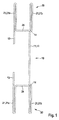
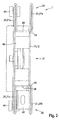
- Fig. 2 shows a plan view of a stanchion 1, the stanchion body 10 according to Fig. 1 having.
- the push bar 40 is arranged in the stanchion body 10.
- the slide 40 may have rollers 41, so that the stanchion is displaceable along a commercial vehicle body.
- the slide 40 is slidably mounted in the guide rail 11 and has a locking means in order to lock the slide 40 in different height positions along the guide rail 11 can.
- a fixing device 30 can be seen, which is arranged in one of the holding devices 20.
- the fixing device 30 is formed in the present embodiment as an angle plate, which may be fixed for example by screwing in the holding device 20.
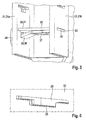
- the possibilities of arranging a fixing device 30 in the holding device 20 are in Fig. 3 clearly visible.
- Fig. 3 shows in perspective view a Rungengrundêt with two holding devices 20.
- Each holding device 20 has two profile legs 21.
- the profile legs 21 each include openings 23, which allow the inclusion of a fixing device 30.
- the openings 23 are arranged in the profile legs 21 at regular intervals from each other.
- an arbitrary height can be selected for the fixing device 30 in a simple manner, and the fixing device 30 can be firmly connected to the holding device 20 at the desired height.
- the fixing device 30 or the in Fig. 3 illustrated angle plate having a hooking element which engages in the slot-shaped openings 23 of the one profile limb 21.
- the fixing device 30 may be screwed, for example.
- the opposite profile leg 21 has two holes 26, whose distance is dimensioned so that holes in the fixing device 30 with the holes 26 in the profile leg 21 can be aligned coaxially with each other.
- the fixing device 30 can be easily and securely screwed to the holding device 20.
- the fixing device 30 may essentially form a support for a load securing device 50, for example a load securing bar 53.
- the fixing device 30 can be arranged in different height positions along the stanchion body 10.
- the user of the stanchion or of a utility vehicle can decide, simply and spontaneously, at which height the load securing device 50 should be placed.
- a load securing system which comprises a stanchion 1 with a stanchion body 10 and a fixing device 30.
- the Rungengrundêt 10 is formed integrally with two holding devices 20 from a multi-folded sheet metal part.
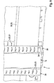
- the main body of the stanchions 10 has a stanchion body profile which corresponds to the stanchion body profile according to FIG Fig. 1 equivalent.
- the openings 23 in the profile legs 21 of the holding device 20 each as a slot-shaped Openings are formed.
- a slot-shaped opening in each case of a profile leg 21 of a holding device 20 has an additional recess.
- each holding device 20 has two profile legs 21.
- An outer profile leg 21a is preferably turned to the outside of the commercial vehicle body in the assembled state of the stanchion 1 on a commercial vehicle body.
- Essentially parallel to the outer profile limb 21a extends an inner profile limb 21b of the holding device 20, which faces the loading space of the commercial vehicle body in the mounted state.
- the inner profile leg 21a has a plurality of substantially rectangular, slot-shaped openings 23.
- the openings 23 in the inner profile leg 21b are arranged at regular intervals from each other. However, it is also possible to provide irregular distances.
- the outer profile leg 21a also has substantially rectangular, slot-shaped openings 23, which are each aligned in a plane with the openings 23 of the inner profile leg 21b.
- the openings 23 in the outer profile limb 21a furthermore each include a lower recess, so that the openings 23 in the outer profile limb 21a have a substantially T-shaped contour ( Fig. 6 ).
- the profile legs 21 may have the same or different lengths.
- the inner profile leg 21b may be shorter than the outer profile leg 21a, or vice versa.
- the length of the profile limb 21 in the longitudinal direction of the vehicle, in particular in a horizontal plane, is measured.
- the back plate 12 is arranged in the assembled state of the stanchion 1 on a commercial vehicle body on an outer side of the commercial vehicle body.
- a fixing device 30 is inserted into a holding device 20 of the stanchion 1.
- the fixing device 30 is in this case designed so that it can be mounted without tools and disassembled, that is fixable without tools in the holding device 20 and from the holding device 20 is releasable.
- the fixing device 30 comprises a Einsteckblech 31, which is formed substantially as an angle plate.
- the insertion plate 31 comprises a support leg 33 and a gripping limb 34.
- the support limb 33 and the gripping limb 34 are arranged essentially at right angles to one another.
- the support leg 33 is positioned in the assembled state between the profile legs 21 of the holding device 20.
- the support leg 33 comprises an opening or a cutout 37.
- a spring 35 is provided whose width substantially corresponds to the width of an opening 23 in the inner profile leg 21b.
- the support leg 33 itself has a width which is greater than the width of the opening 23 of the inner profile leg 21b. Thus, the support leg 33 can be plugged into the opening 23 of the inner profile leg 21b.
- the opening 23 in the outer profile limb 21 a has a width which essentially corresponds to the width of the support limb 33. This ensures that the support leg 33 or generally the Einsteckblech 31 can be passed through the outer profile leg 21a.
- the gripping leg 34 is arranged outside the outer profile limb 21a in the mounted state of the fixing device 30 or of the insertion plate 31. In particular, the gripping limb 34 can be arranged at a distance from the outer surface of the outer profile limb 21a, so that a user can grasp the gripping limb 34 easily.
- Fig. 6 shows an opening 23 in a, preferably outer, profile leg 21 of a holding device 20.
- the opening 23 has a substantially rectangular base profile, to which a recess 25 connects.
- the recess 25 forms with the opening 23 a substantially T-shaped opening or opening contour.
- the detent spring 32 With the Einsteckblech 31 of the fixing device 30 is firmly connected to a detent spring 32. Specifically, the detent spring 32 with the support leg 33 is fixed connected. The detent spring 32 is arranged on a side facing the grip leg 34 of the support leg 33. Analogous to the support leg 33 and the detent spring 32 includes a cutout for weight savings.
- the detent spring 32 has a deflection section 36 which protrudes from the support leg 33 in an idle state.
- the deflection portion 36 is flexible and can be moved against a spring force in the direction of the support leg 33.
- the detent spring 32 causes a fixation or captive arrangement of the Einsteckblechs 31 and the fixing device 30 in the holding device 20th
- the Einsteckblech 31 and the detent spring 32 may also be integrally, in particular integrally formed.
- a deflection section 36 can be provided in the support leg 33 of the insertion plate 31.
- a sub-segment of the support leg 33 can be exposed in particular by a U-shaped cut in the support leg 33 and at least partially bent out of the plane of the support leg 33 to form the projecting in an idle state of the support leg 33 projecting portion 36.
- the deflection portion 36 is arranged in a one-piece design with the support leg 33 between the handle leg 34 and the cutout 37.
- Fig. 5 the fixing device 30 is shown in a mounted position in the holding device 20.
- the fixing device 30 is then pushed further until the spring 35 of the Einsteckblechs 31 passes into the opening 23 of the inner profile leg 21b.
- the Einsteckblechs 31 of the deflection portion 36 of the detent spring 32 is deflected in the direction of the support leg 32 and can thus pass through the recess 25 in the opening 23 of the outer profile leg 21.
- the spring force of the detent spring 32 causes the deflection section 36 to move into a position projecting from the support limb 33 and thus block a rearward movement of the fixation device 30 through the opening 23 in the outer profile limb 21a.
- the fixing device 30 can no longer be pulled out of the holding device 20.
- the deflection section 36 for example manually, in the direction of the support leg 33 is pressed so that the detent spring 32 can again pass through the opening 23 in the outer profile leg 21a. In this way, a particularly simple fixation of the fixing device 30 is possible, wherein a tool for fixing the fixing device 30 to the holding device 20 can be dispensed with.
- the fixing device 30 can be set in any desired height and individually for the particular requirement.
- the fixing device 30 can be used as a support for a load securing device, such as a load securing bar 53.
- a load securing device such as a load securing bar 53.
- Fig. 10 shows in concrete terms a detailed view of a stanchion 1, which is attached to a vehicle frame 2.
- the stanchion 1 has a stanchion body 10 with two holding devices 20, wherein the stanchion body 10 and the holding device 20 essentially have a stanchion body profile, as shown in FIG Fig. 4 is shown.
- the holding device has a plurality of receiving means 22 in the profile legs 21, which are formed as apertures 23.
- a fixing device 30 is arranged in a lowermost receiving means 22 in a lowermost receiving means 22 in a lowermost receiving means 22.
- the fixing device 30 is analogous to the embodiment according to FIG Fig. 8 and 9 educated.
- the fixing device 30 forms with the support leg 33 of the Einsteckblechs 31 a support for a load securing bar 53.
- the load securing bar 53 can thus be easily inserted into the holding device 20 and then rests on the fixing device 30.
- the load securing bar 53 can be used in particular as a pallet stop.
- a plurality of load securing devices 50 in particular a plurality of load securing slats 53, can be arranged along the main body of the rungs 10. It is also possible to adjust the height of the individual load securing slats 53 individually. For this purpose, only the fixing device 30 is to be released from the holding device 20 and connected in a different height position with the receiving means 22 of the holding device 20. This can be done without tools, whereby the handling is easier.
- a direct comparison between two middle stanchions is shown in a partial side view of a commercial vehicle body, wherein the middle stanchion shown in the left half of the picture in conventional construction and the middle stanchion shown in the right half of the invention is formed according to the invention.
- similar components of the two stanchions are provided with the same reference numerals, wherein the components of the conventional stanchion 1 'are marked with an apostrophe. Both stanchions are connected to the vehicle frame 2 of Nutzrhusitatis.
- the conventional stanchion 1 comprises a stanchion body 10', which essentially forms a C-profile.
- the C-profile serves as a guide rail 11 'for a slide 40'.
- a plurality of holding devices 20' are arranged, which are each formed as a slatted pockets.
- the holding devices 20 'each comprise two profile legs 21', which are arranged substantially parallel to one another.
- a support surface is formed, so that the holding device 20 'substantially forms a U-shaped pocket.
- the holding devices 20 ' are fixedly arranged on the stanchion body 10, in particular riveted, wherein a flexible height displacement is prevented.
- the stanchion body 10 has a corresponding hole pattern, so that the holding devices 20 'can be arranged in different height positions. However, this is only possible in the production of the conventional stanchion 1 '. A later conversion of the holding device 20 'is not provided.
- the holding device 20 is formed substantially over the entire length of the Rungengrund stresses 10 and fixed, in particular in one piece, connected to the Runge body 10.
- the profile legs 21 have openings 23 which are accessible from the side.
- the fixing device 30 can be easily inserted from the outside into the holding device 20. This makes it possible to make a particularly simple and quick height adjustment for the load securing slats 53.
- the cross-sectional profile of the stanchion body 10 according to Fig. 10 corresponds essentially to the cross-sectional profile of the stanchion body according to Fig. 4 ,
- the holding device 20 can not only be used for receiving load securing slats, but also capable of accommodating alternative load securing devices 50.
- a fastening rail 51 is shown, which has a substantially U-shaped cross-sectional profile which can be arranged between the profile legs 21 of the holding device 20.
- the fixation of the fastening rail 51 can take place via the fixing device 30.
- the fastening rail 51 has corresponding openings, through which the fixing device 30 can be guided. The fixing device 30 can thus lock the fastening rail 51 in the holding device 20.
- the fastening rail 51 preferably has a plurality of openings, in particular keyhole openings 52.
- the keyhole openings 52 may be arranged regularly along the mounting rail 51.
- the fastening rail 51 itself may extend over the entire length of the holding device 20 or only over part of the length of the holding device 20.
- the fastening rail 51 makes it possible to attach other load securing devices 50 to the stanchion 1.
- load securing bars or load securing bars formed with corresponding counterparts may be connected to the mounting rail 51.
- grid-like load securing devices 50 could be connected in this way with the mounting rail 51 and the stanchion 1.
- the holding device 20 formed on the main body 10 of the holding means 20 with the plurality of receiving means allows a high degree of flexibility in the selection of load securing devices 50.
- FIGS. 12 and 13 show in detail a perspective view of a further fixing device 30 for a holding device 20 of a Runge according to the invention according to a further particularly preferred embodiment.
- Fig. 12 hereby represents a bottom view and Fig. 13 a lateral view of the fixing device 30.
- the fixing device 30 is integrally formed as a U-shaped profile with a bottom 61 and two parallel legs 60.
- a crank 14 is formed adjacent to the bottom.
- the fixing device 30 can be bent over a large area.
- the bottom 61 is formed flattened such that a load securing device 50, for example a load securing bar 53 can rest completely on the floor 61.
- a rivet 62 is attached to an outer side 67 in each case.
- a rivet head 62a of the respective rivet 62 may expediently protrude on the outside 67 of the leg 60.
- the rivets 62 may each be connected via an associated opening with the respective leg 60.
- the rivet 62 extends through the opening in the respective leg 60 and is deformed on an inner side 66 of the leg 60, so that the rivet 62 with the rivet head 62a on the outer side 67 is positively connected to the leg 60.
- the rivet head 62a can engage in the holding means 20 in the associated receiving means of the holding device 20 for fixing, so that the fixing device 30 can be fixed in the holding device 20 at a certain height.
- the rivets 62 are arranged, for example, on the legs 60 on the opposite side of the bottom 61.
- the fixing device 30 is advantageously formed from a flexible sheet metal, such as spring steel.
- a wing 63 is attached to an inner side 66 of the leg 60.
- the inside 66 is oriented in the direction of the profile center of the U-shaped profile.
- the wings 63 are expediently perpendicular to the legs 60.
- the wings 63 each have a rectangular shape with an engagement opening 64.
- the engagement opening 64 is formed as a bore. Through the engagement opening 64 can engage a circlip pliers, whereby the legs 60 of the fixing device 30 are bent by means of the wings 63 inwardly and thus can be easily inserted into the holding device 20.
- the wings 63 are arranged, for example, centrally on a free edge 68 of the respective leg 60.
- the free edge 68 of the leg 60 is disposed at the opposite end of the bottom 61 of the leg 60.
- an incision 65 is formed on the right-hand side and left-hand side of the vane 63.
- Fig. 14 shows a perspective view of a lower part of a Runge according to the invention according to a further particularly preferred embodiment with a fixing device 30 according to Fig. 12 ,
- the stanchion has a holding device 20 for a load securing device 50, which is formed by two profile legs 21 arranged parallel to one another and arranged on the vehicle frame 2.
- the profile legs 21 each include receiving means 22 for the fixing device 30, which are arranged in alignment with each other.
- the receiving means 22 are formed as bores.
- the receiving means 22 are arranged at regular intervals in different height positions on the profile legs 21.
- the rivets 62 of the fixing device 30 can engage, whereby the fixing device 30 can be fixedly connected to the holding device 20.
- the fixing device 30 can be easily removed from the holding device 20 by means of a circlip pliers and, if necessary, mounted in a different height position.
- the bottom 61 of the fixing device 30 can form a stable support for a load securing device 50.
- the user of the commercial vehicle can decide in what amount the load securing device 50 should be placed.
- Exemplary are in Fig. 15 two fixing devices 30 are arranged in different height positions in the holding device 20.
- a plurality of load securing devices 50 can be very flexibly mounted in the holding device 20.
Landscapes
- Engineering & Computer Science (AREA)
- Chemical & Material Sciences (AREA)
- Combustion & Propulsion (AREA)
- Transportation (AREA)
- Mechanical Engineering (AREA)
- Fittings On The Vehicle Exterior For Carrying Loads, And Devices For Holding Or Mounting Articles (AREA)
- Vehicle Cleaning, Maintenance, Repair, Refitting, And Outriggers (AREA)
Priority Applications (1)
| Application Number | Priority Date | Filing Date | Title |
|---|---|---|---|
| PL16182973T PL3127789T3 (pl) | 2015-08-05 | 2016-08-05 | Kłonica do nadwozia pojazdu użytkowego i system zabezpieczenia ładunku, nadwozie pojazdu użytkowego i pojazd użytkowy z taką kłonicą |
Applications Claiming Priority (1)
| Application Number | Priority Date | Filing Date | Title |
|---|---|---|---|
| DE102015112843.8A DE102015112843B4 (de) | 2015-08-05 | 2015-08-05 | Runge für einen Nutzfahrzeugaufbau sowie Ladungssicherungssystem, Nutzfahrzeugaufbau und Nutzfahrzeug mit einer solchen Runge |
Publications (3)
| Publication Number | Publication Date |
|---|---|
| EP3127789A2 true EP3127789A2 (fr) | 2017-02-08 |
| EP3127789A3 EP3127789A3 (fr) | 2017-02-15 |
| EP3127789B1 EP3127789B1 (fr) | 2019-10-23 |
Family
ID=56618018
Family Applications (1)
| Application Number | Title | Priority Date | Filing Date |
|---|---|---|---|
| EP16182973.4A Active EP3127789B1 (fr) | 2015-08-05 | 2016-08-05 | Ranche pour un montage de véhicule utilitaire et système de sécurisation de charge, montage de véhicule utilitaire et véhicule utilitaire comprenant une telle ranche |
Country Status (4)
| Country | Link |
|---|---|
| EP (1) | EP3127789B1 (fr) |
| DE (1) | DE102015112843B4 (fr) |
| ES (1) | ES2767623T3 (fr) |
| PL (1) | PL3127789T3 (fr) |
Cited By (2)
| Publication number | Priority date | Publication date | Assignee | Title |
|---|---|---|---|---|
| BE1028140B1 (nl) * | 2020-03-11 | 2021-10-11 | A & D Trucks & Trailers Opbouw Nv | Zeiloplegger met verstevigde voor- en achterkader en werkwijze voor laden van dergelijke zeiloplegger |
| EP3543052B1 (fr) * | 2018-03-23 | 2023-11-22 | Kögel Trailer GmbH | Carrosserie de véhicule utilitaire et véhicule utilitaire |
Families Citing this family (1)
| Publication number | Priority date | Publication date | Assignee | Title |
|---|---|---|---|---|
| JP2024518456A (ja) | 2021-05-07 | 2024-05-01 | レドキック、 オーワイ | 貨物輸送オペレーションのリスク確率評価及びその使用の方法 |
Citations (1)
| Publication number | Priority date | Publication date | Assignee | Title |
|---|---|---|---|---|
| EP1816057A2 (fr) | 2006-02-01 | 2007-08-08 | F. HESTERBERG & SÖHNE GmbH & Co. KG | Système de montants pour véhicules utilitaires |
Family Cites Families (7)
| Publication number | Priority date | Publication date | Assignee | Title |
|---|---|---|---|---|
| EP1145938A1 (fr) * | 2000-04-11 | 2001-10-17 | Scolastica Frizzo | Rehausse de montant pour le rehaussement de la caisse de camions, remorques et semi-remorques |
| US6872039B2 (en) * | 2003-04-23 | 2005-03-29 | Pivot Point, Incorporated | Self-locking pin |
| DE202006007873U1 (de) * | 2006-05-15 | 2006-07-27 | Trw Automotive Gmbh | Befestigungselement |
| ES2388796T5 (es) * | 2008-11-10 | 2017-03-16 | F. Hesterberg & Söhne Gmbh & Co. Kg | Soporte de listones para superestructuras de vehículos industriales |
| US20150159684A1 (en) * | 2013-12-09 | 2015-06-11 | Ancra International Llc | Releasable mounting system for logistics track |
| DE202014003055U1 (de) * | 2014-04-03 | 2014-05-20 | Fahrzeugbau Karl Tang Gmbh | Schiene zur Sicherung von Ladung |
| PL2993112T3 (pl) * | 2014-09-05 | 2019-07-31 | Helmut Fliegl | Układ kłonicy dla konstrukcji dachu nadwozia pojazdu użytkowego lub przyczepy |
-
2015
- 2015-08-05 DE DE102015112843.8A patent/DE102015112843B4/de active Active
-
2016
- 2016-08-05 EP EP16182973.4A patent/EP3127789B1/fr active Active
- 2016-08-05 PL PL16182973T patent/PL3127789T3/pl unknown
- 2016-08-05 ES ES16182973T patent/ES2767623T3/es active Active
Patent Citations (1)
| Publication number | Priority date | Publication date | Assignee | Title |
|---|---|---|---|---|
| EP1816057A2 (fr) | 2006-02-01 | 2007-08-08 | F. HESTERBERG & SÖHNE GmbH & Co. KG | Système de montants pour véhicules utilitaires |
Cited By (2)
| Publication number | Priority date | Publication date | Assignee | Title |
|---|---|---|---|---|
| EP3543052B1 (fr) * | 2018-03-23 | 2023-11-22 | Kögel Trailer GmbH | Carrosserie de véhicule utilitaire et véhicule utilitaire |
| BE1028140B1 (nl) * | 2020-03-11 | 2021-10-11 | A & D Trucks & Trailers Opbouw Nv | Zeiloplegger met verstevigde voor- en achterkader en werkwijze voor laden van dergelijke zeiloplegger |
Also Published As
| Publication number | Publication date |
|---|---|
| EP3127789B1 (fr) | 2019-10-23 |
| DE102015112843B4 (de) | 2021-01-28 |
| PL3127789T3 (pl) | 2020-05-18 |
| EP3127789A3 (fr) | 2017-02-15 |
| ES2767623T3 (es) | 2020-06-18 |
| DE102015112843A1 (de) | 2017-02-09 |
Similar Documents
| Publication | Publication Date | Title |
|---|---|---|
| EP2458301B1 (fr) | Dispositif d'agencement d'au moins un module solaire dans un sous-sol | |
| EP2606766A1 (fr) | Guidage d'extraction pour tiroirs coulissants avec crochet de préhension | |
| DE202015005791U1 (de) | Transport- und/oder Lagergestell | |
| EP3746627B1 (fr) | Équerre de fixation pour le montage des rails supérieurs des stores vénitiens | |
| AT518211B1 (de) | Runge für einen nutzfahrzeug- oder anhängeraufbau | |
| EP3127789B1 (fr) | Ranche pour un montage de véhicule utilitaire et système de sécurisation de charge, montage de véhicule utilitaire et véhicule utilitaire comprenant une telle ranche | |
| EP2977267A1 (fr) | Porte-charge pour vehicules utilitaires, en particulier sous forme d'une galerie | |
| EP1816057B1 (fr) | Système de montants pour véhicules utilitaires | |
| DE102014110953B4 (de) | System zur Befestigung von mit Rollen versehenen Wagen in einem Fahrzeug | |
| DE202008014035U1 (de) | Ladesicherung | |
| DE102018122634B4 (de) | Ladungs-Sicherungs-System sowie Fahrzeug umfassend ein solches System und ein Verfahren zur Ladungs-Sicherung | |
| EP3071896B1 (fr) | Support de montage pour une enceinte et méthode de monter une enceinte utilisant ledit support | |
| EP4131682A1 (fr) | Pièce tête de liaison permettant de fixer une tige de suspension d'un système de porte-câble à un plafond | |
| EP2460698B1 (fr) | Dispositif de réglage en hauteur pour ceintures de sécurité de véhicules | |
| DE102007033021B4 (de) | Sattelauflieger mit einer Vorrichtung zur Sicherung der Ladung | |
| EP0451616B1 (fr) | Plate-forme d'échafaudage | |
| EP2837549B1 (fr) | Rancher de véhicule utilitaire | |
| EP1857322B1 (fr) | Latte d'introduction pour un véhicule de transport, création pour la surface de charge d'un véhicule de transport et véhicule de transport | |
| EP3785983B1 (fr) | Rail de plancher pour un véhicule, dispositif de montage et véhicule | |
| DE10043296B4 (de) | Höhenverstellbare Klapprunge | |
| EP2993112B1 (fr) | Système de montants pour structure de toit de véhicule utilitaire ou de remorque | |
| DE102008025440B4 (de) | Einstecklatte für einen Aufbau eines Transportfahrzeugs, Aufbau für die Ladefläche eines Transportfahrzeugs, eines Lastkraftwagens, eines Aufliegers oder Anhängers für einen Lastkraftwagen mit einer solchen Einstecklatte und Transportfahrzeug, Lastkraftwagen, Auflieger oder Anhänger für einen Lastkraftwagen mit einer Ladefläche und einem solchen Aufbau. | |
| EP3483047B1 (fr) | Dispositif de retenue pour un véhicule utilitaire, agencement d'un rancher doté d'un dispositif de retenue, véhicule utilitaire, procédé de fabrication d'un dispositif de retenue et procédé de montage d'un dispositif de retenue sur un rancher | |
| EP1375313A2 (fr) | Véhicule automobile | |
| EP3922510B1 (fr) | Guidage de rail, agencement de siège et véhicule |
Legal Events
| Date | Code | Title | Description |
|---|---|---|---|
| PUAI | Public reference made under article 153(3) epc to a published international application that has entered the european phase |
Free format text: ORIGINAL CODE: 0009012 |
|
| STAA | Information on the status of an ep patent application or granted ep patent |
Free format text: STATUS: THE APPLICATION HAS BEEN PUBLISHED |
|
| PUAL | Search report despatched |
Free format text: ORIGINAL CODE: 0009013 |
|
| AK | Designated contracting states |
Kind code of ref document: A2 Designated state(s): AL AT BE BG CH CY CZ DE DK EE ES FI FR GB GR HR HU IE IS IT LI LT LU LV MC MK MT NL NO PL PT RO RS SE SI SK SM TR |
|
| AX | Request for extension of the european patent |
Extension state: BA ME |
|
| AK | Designated contracting states |
Kind code of ref document: A3 Designated state(s): AL AT BE BG CH CY CZ DE DK EE ES FI FR GB GR HR HU IE IS IT LI LT LU LV MC MK MT NL NO PL PT RO RS SE SI SK SM TR |
|
| AX | Request for extension of the european patent |
Extension state: BA ME |
|
| RIC1 | Information provided on ipc code assigned before grant |
Ipc: B62D 33/02 20060101AFI20170110BHEP |
|
| STAA | Information on the status of an ep patent application or granted ep patent |
Free format text: STATUS: REQUEST FOR EXAMINATION WAS MADE |
|
| 17P | Request for examination filed |
Effective date: 20170802 |
|
| RBV | Designated contracting states (corrected) |
Designated state(s): AL AT BE BG CH CY CZ DE DK EE ES FI FR GB GR HR HU IE IS IT LI LT LU LV MC MK MT NL NO PL PT RO RS SE SI SK SM TR |
|
| STAA | Information on the status of an ep patent application or granted ep patent |
Free format text: STATUS: EXAMINATION IS IN PROGRESS |
|
| 17Q | First examination report despatched |
Effective date: 20180309 |
|
| RAP1 | Party data changed (applicant data changed or rights of an application transferred) |
Owner name: KOEGEL TRAILER GMBH |
|
| GRAP | Despatch of communication of intention to grant a patent |
Free format text: ORIGINAL CODE: EPIDOSNIGR1 |
|
| STAA | Information on the status of an ep patent application or granted ep patent |
Free format text: STATUS: GRANT OF PATENT IS INTENDED |
|
| INTG | Intention to grant announced |
Effective date: 20190523 |
|
| GRAS | Grant fee paid |
Free format text: ORIGINAL CODE: EPIDOSNIGR3 |
|
| GRAA | (expected) grant |
Free format text: ORIGINAL CODE: 0009210 |
|
| STAA | Information on the status of an ep patent application or granted ep patent |
Free format text: STATUS: THE PATENT HAS BEEN GRANTED |
|
| AK | Designated contracting states |
Kind code of ref document: B1 Designated state(s): AL AT BE BG CH CY CZ DE DK EE ES FI FR GB GR HR HU IE IS IT LI LT LU LV MC MK MT NL NO PL PT RO RS SE SI SK SM TR |
|
| REG | Reference to a national code |
Ref country code: GB Ref legal event code: FG4D Free format text: NOT ENGLISH |
|
| REG | Reference to a national code |
Ref country code: CH Ref legal event code: EP |
|
| REG | Reference to a national code |
Ref country code: IE Ref legal event code: FG4D Free format text: LANGUAGE OF EP DOCUMENT: GERMAN |
|
| REG | Reference to a national code |
Ref country code: DE Ref legal event code: R096 Ref document number: 502016007195 Country of ref document: DE |
|
| REG | Reference to a national code |
Ref country code: AT Ref legal event code: REF Ref document number: 1193339 Country of ref document: AT Kind code of ref document: T Effective date: 20191115 |
|
| REG | Reference to a national code |
Ref country code: NL Ref legal event code: MP Effective date: 20191023 |
|
| REG | Reference to a national code |
Ref country code: LT Ref legal event code: MG4D |
|
| PG25 | Lapsed in a contracting state [announced via postgrant information from national office to epo] |
Ref country code: NO Free format text: LAPSE BECAUSE OF FAILURE TO SUBMIT A TRANSLATION OF THE DESCRIPTION OR TO PAY THE FEE WITHIN THE PRESCRIBED TIME-LIMIT Effective date: 20200123 Ref country code: GR Free format text: LAPSE BECAUSE OF FAILURE TO SUBMIT A TRANSLATION OF THE DESCRIPTION OR TO PAY THE FEE WITHIN THE PRESCRIBED TIME-LIMIT Effective date: 20200124 Ref country code: LT Free format text: LAPSE BECAUSE OF FAILURE TO SUBMIT A TRANSLATION OF THE DESCRIPTION OR TO PAY THE FEE WITHIN THE PRESCRIBED TIME-LIMIT Effective date: 20191023 Ref country code: NL Free format text: LAPSE BECAUSE OF FAILURE TO SUBMIT A TRANSLATION OF THE DESCRIPTION OR TO PAY THE FEE WITHIN THE PRESCRIBED TIME-LIMIT Effective date: 20191023 Ref country code: LV Free format text: LAPSE BECAUSE OF FAILURE TO SUBMIT A TRANSLATION OF THE DESCRIPTION OR TO PAY THE FEE WITHIN THE PRESCRIBED TIME-LIMIT Effective date: 20191023 Ref country code: SE Free format text: LAPSE BECAUSE OF FAILURE TO SUBMIT A TRANSLATION OF THE DESCRIPTION OR TO PAY THE FEE WITHIN THE PRESCRIBED TIME-LIMIT Effective date: 20191023 Ref country code: PT Free format text: LAPSE BECAUSE OF FAILURE TO SUBMIT A TRANSLATION OF THE DESCRIPTION OR TO PAY THE FEE WITHIN THE PRESCRIBED TIME-LIMIT Effective date: 20200224 Ref country code: BG Free format text: LAPSE BECAUSE OF FAILURE TO SUBMIT A TRANSLATION OF THE DESCRIPTION OR TO PAY THE FEE WITHIN THE PRESCRIBED TIME-LIMIT Effective date: 20200123 Ref country code: FI Free format text: LAPSE BECAUSE OF FAILURE TO SUBMIT A TRANSLATION OF THE DESCRIPTION OR TO PAY THE FEE WITHIN THE PRESCRIBED TIME-LIMIT Effective date: 20191023 |
|
| PG25 | Lapsed in a contracting state [announced via postgrant information from national office to epo] |
Ref country code: RS Free format text: LAPSE BECAUSE OF FAILURE TO SUBMIT A TRANSLATION OF THE DESCRIPTION OR TO PAY THE FEE WITHIN THE PRESCRIBED TIME-LIMIT Effective date: 20191023 Ref country code: IS Free format text: LAPSE BECAUSE OF FAILURE TO SUBMIT A TRANSLATION OF THE DESCRIPTION OR TO PAY THE FEE WITHIN THE PRESCRIBED TIME-LIMIT Effective date: 20200224 Ref country code: HR Free format text: LAPSE BECAUSE OF FAILURE TO SUBMIT A TRANSLATION OF THE DESCRIPTION OR TO PAY THE FEE WITHIN THE PRESCRIBED TIME-LIMIT Effective date: 20191023 |
|
| REG | Reference to a national code |
Ref country code: ES Ref legal event code: FG2A Ref document number: 2767623 Country of ref document: ES Kind code of ref document: T3 Effective date: 20200618 |
|
| PG25 | Lapsed in a contracting state [announced via postgrant information from national office to epo] |
Ref country code: AL Free format text: LAPSE BECAUSE OF FAILURE TO SUBMIT A TRANSLATION OF THE DESCRIPTION OR TO PAY THE FEE WITHIN THE PRESCRIBED TIME-LIMIT Effective date: 20191023 |
|
| REG | Reference to a national code |
Ref country code: DE Ref legal event code: R097 Ref document number: 502016007195 Country of ref document: DE |
|
| PG2D | Information on lapse in contracting state deleted |
Ref country code: IS |
|
| PG25 | Lapsed in a contracting state [announced via postgrant information from national office to epo] |
Ref country code: EE Free format text: LAPSE BECAUSE OF FAILURE TO SUBMIT A TRANSLATION OF THE DESCRIPTION OR TO PAY THE FEE WITHIN THE PRESCRIBED TIME-LIMIT Effective date: 20191023 Ref country code: DK Free format text: LAPSE BECAUSE OF FAILURE TO SUBMIT A TRANSLATION OF THE DESCRIPTION OR TO PAY THE FEE WITHIN THE PRESCRIBED TIME-LIMIT Effective date: 20191023 Ref country code: RO Free format text: LAPSE BECAUSE OF FAILURE TO SUBMIT A TRANSLATION OF THE DESCRIPTION OR TO PAY THE FEE WITHIN THE PRESCRIBED TIME-LIMIT Effective date: 20191023 Ref country code: IS Free format text: LAPSE BECAUSE OF FAILURE TO SUBMIT A TRANSLATION OF THE DESCRIPTION OR TO PAY THE FEE WITHIN THE PRESCRIBED TIME-LIMIT Effective date: 20200223 |
|
| PLBE | No opposition filed within time limit |
Free format text: ORIGINAL CODE: 0009261 |
|
| STAA | Information on the status of an ep patent application or granted ep patent |
Free format text: STATUS: NO OPPOSITION FILED WITHIN TIME LIMIT |
|
| PG25 | Lapsed in a contracting state [announced via postgrant information from national office to epo] |
Ref country code: SM Free format text: LAPSE BECAUSE OF FAILURE TO SUBMIT A TRANSLATION OF THE DESCRIPTION OR TO PAY THE FEE WITHIN THE PRESCRIBED TIME-LIMIT Effective date: 20191023 Ref country code: SK Free format text: LAPSE BECAUSE OF FAILURE TO SUBMIT A TRANSLATION OF THE DESCRIPTION OR TO PAY THE FEE WITHIN THE PRESCRIBED TIME-LIMIT Effective date: 20191023 |
|
| 26N | No opposition filed |
Effective date: 20200724 |
|
| PG25 | Lapsed in a contracting state [announced via postgrant information from national office to epo] |
Ref country code: SI Free format text: LAPSE BECAUSE OF FAILURE TO SUBMIT A TRANSLATION OF THE DESCRIPTION OR TO PAY THE FEE WITHIN THE PRESCRIBED TIME-LIMIT Effective date: 20191023 |
|
| PG25 | Lapsed in a contracting state [announced via postgrant information from national office to epo] |
Ref country code: MC Free format text: LAPSE BECAUSE OF FAILURE TO SUBMIT A TRANSLATION OF THE DESCRIPTION OR TO PAY THE FEE WITHIN THE PRESCRIBED TIME-LIMIT Effective date: 20191023 |
|
| REG | Reference to a national code |
Ref country code: CH Ref legal event code: PL |
|
| GBPC | Gb: european patent ceased through non-payment of renewal fee |
Effective date: 20200805 |
|
| PG25 | Lapsed in a contracting state [announced via postgrant information from national office to epo] |
Ref country code: CH Free format text: LAPSE BECAUSE OF NON-PAYMENT OF DUE FEES Effective date: 20200831 Ref country code: LI Free format text: LAPSE BECAUSE OF NON-PAYMENT OF DUE FEES Effective date: 20200831 Ref country code: LU Free format text: LAPSE BECAUSE OF NON-PAYMENT OF DUE FEES Effective date: 20200805 |
|
| REG | Reference to a national code |
Ref country code: BE Ref legal event code: MM Effective date: 20200831 |
|
| PG25 | Lapsed in a contracting state [announced via postgrant information from national office to epo] |
Ref country code: FR Free format text: LAPSE BECAUSE OF NON-PAYMENT OF DUE FEES Effective date: 20200831 |
|
| PG25 | Lapsed in a contracting state [announced via postgrant information from national office to epo] |
Ref country code: BE Free format text: LAPSE BECAUSE OF NON-PAYMENT OF DUE FEES Effective date: 20200831 Ref country code: GB Free format text: LAPSE BECAUSE OF NON-PAYMENT OF DUE FEES Effective date: 20200805 Ref country code: IE Free format text: LAPSE BECAUSE OF NON-PAYMENT OF DUE FEES Effective date: 20200805 |
|
| PG25 | Lapsed in a contracting state [announced via postgrant information from national office to epo] |
Ref country code: MT Free format text: LAPSE BECAUSE OF FAILURE TO SUBMIT A TRANSLATION OF THE DESCRIPTION OR TO PAY THE FEE WITHIN THE PRESCRIBED TIME-LIMIT Effective date: 20191023 Ref country code: CY Free format text: LAPSE BECAUSE OF FAILURE TO SUBMIT A TRANSLATION OF THE DESCRIPTION OR TO PAY THE FEE WITHIN THE PRESCRIBED TIME-LIMIT Effective date: 20191023 |
|
| PG25 | Lapsed in a contracting state [announced via postgrant information from national office to epo] |
Ref country code: MK Free format text: LAPSE BECAUSE OF FAILURE TO SUBMIT A TRANSLATION OF THE DESCRIPTION OR TO PAY THE FEE WITHIN THE PRESCRIBED TIME-LIMIT Effective date: 20191023 |
|
| PGFP | Annual fee paid to national office [announced via postgrant information from national office to epo] |
Ref country code: ES Payment date: 20250916 Year of fee payment: 10 |
|
| PGFP | Annual fee paid to national office [announced via postgrant information from national office to epo] |
Ref country code: DE Payment date: 20250829 Year of fee payment: 10 |
|
| PGFP | Annual fee paid to national office [announced via postgrant information from national office to epo] |
Ref country code: IT Payment date: 20250825 Year of fee payment: 10 Ref country code: TR Payment date: 20250717 Year of fee payment: 10 Ref country code: PL Payment date: 20250709 Year of fee payment: 10 |
|
| PGFP | Annual fee paid to national office [announced via postgrant information from national office to epo] |
Ref country code: AT Payment date: 20250819 Year of fee payment: 10 |
|
| PGFP | Annual fee paid to national office [announced via postgrant information from national office to epo] |
Ref country code: CZ Payment date: 20250717 Year of fee payment: 10 |