EP3127831A1 - Strangdosierer zum ausbringen von cremes - Google Patents
Strangdosierer zum ausbringen von cremes Download PDFInfo
- Publication number
- EP3127831A1 EP3127831A1 EP16181720.0A EP16181720A EP3127831A1 EP 3127831 A1 EP3127831 A1 EP 3127831A1 EP 16181720 A EP16181720 A EP 16181720A EP 3127831 A1 EP3127831 A1 EP 3127831A1
- Authority
- EP
- European Patent Office
- Prior art keywords
- tube
- strand
- metering
- metering wheel
- piston
- Prior art date
- Legal status (The legal status is an assumption and is not a legal conclusion. Google has not performed a legal analysis and makes no representation as to the accuracy of the status listed.)
- Granted
Links
Images


Classifications
-
- B—PERFORMING OPERATIONS; TRANSPORTING
- B65—CONVEYING; PACKING; STORING; HANDLING THIN OR FILAMENTARY MATERIAL
- B65D—CONTAINERS FOR STORAGE OR TRANSPORT OF ARTICLES OR MATERIALS, e.g. BAGS, BARRELS, BOTTLES, BOXES, CANS, CARTONS, CRATES, DRUMS, JARS, TANKS, HOPPERS, FORWARDING CONTAINERS; ACCESSORIES, CLOSURES, OR FITTINGS THEREFOR; PACKAGING ELEMENTS; PACKAGES
- B65D35/00—Pliable tubular containers adapted to be permanently or temporarily deformed to expel contents, e.g. collapsible tubes for toothpaste or other plastic or semi-liquid material; Holders therefor
- B65D35/24—Pliable tubular containers adapted to be permanently or temporarily deformed to expel contents, e.g. collapsible tubes for toothpaste or other plastic or semi-liquid material; Holders therefor with auxiliary devices
- B65D35/40—Pliable tubular containers adapted to be permanently or temporarily deformed to expel contents, e.g. collapsible tubes for toothpaste or other plastic or semi-liquid material; Holders therefor with auxiliary devices for metering discharge
-
- G—PHYSICS
- G01—MEASURING; TESTING
- G01F—MEASURING VOLUME, VOLUME FLOW, MASS FLOW OR LIQUID LEVEL; METERING BY VOLUME
- G01F11/00—Apparatus requiring external operation adapted at each repeated and identical operation to measure and separate a predetermined volume of fluid or fluent solid material from a supply or container, without regard to weight, and to deliver it
- G01F11/02—Apparatus requiring external operation adapted at each repeated and identical operation to measure and separate a predetermined volume of fluid or fluent solid material from a supply or container, without regard to weight, and to deliver it with measuring chambers which expand or contract during measurement
Definitions
- the invention relates to a strand dispenser for dispensing creams according to the preamble of claim 1.
- Dosing pumps for bottles are known from the prior art, but which always work on a displacement piston and sleeve with actuating and return spring and inlet and outlet valves and are not suitable for crushing the Tubenwandung.
- the strand dosage from the tube is achieved by varying the tube outlet, the strand length is always applied differently long.
- the desired application length can only be estimated, whereby the human being with his sense and judgment is usually deceived, so that the user does not get the exact, desired dosage from the tube.
- the object of the invention is to generate a dosing dispenser for tubes, wherein the Tubaausbringhandling is to be mitintegriert in the dosing sequence. Creamy and gel-like products are to be dosed out of the tube by squeezing the tube wall in order to avoid over- or under-dosing and to guarantee the well-known tube handling to the user.
- the dispenser for tubes according to the invention is a dispenser design which can process all media that can be dispensed via a tube.
- the dosing dispenser system is constructed substantially in two parts, i. it is a dispensing element as dosing and closing body and the tube with the outlet valve and the suction valve.
- the two modules are separably coupled to each other via a screw or snap closure, wherein the coupling is designed such that the function of the dosage works only in combination of both modules.
- the content of the tube or squeeze bottle plays a minor role in this context.
- the system is manufactured in different dosing chamber sizes.
- the device according to the invention serves for dosing, dispensing creamy or gel-like products. These may be medicines, cosmetics, adhesives, silicone or another creamy product. These products are preferably provided as tube contents in a tube or squeeze bottle.
- the dispenser according to the invention represents the coatable assembly on a tube or squeeze bottle. Applicable here means that the metering wheel assembly can be screwed onto the tube or squeeze bottle, snapped or clinched or applied in another way.
- the dispenser according to the invention has an actuating wheel with a T-geometry, which includes the metering space and is rotatably connected to the closure element via a rotary axle receptacle.
- the metering wheel with the cylindrical or angular centrically arranged metering chamber is adapted to the product to be delivered in terms of size, extent, volume content or the surface condition of the metering chamber.
- rotating aids can be provided on the metering wheel in the form of concave or convex geometric elements.
- the metering chamber cooperates with a piston which has a spherical or cylindrical shape. This means that the product squeezed out of the tube into the dosing chamber pushes the piston in the direction of the The metering wheel is then rotated manually by 180 °, so that the product can be expressed from the tube at the next application. The piston is moved with the product back to the outlet in the metering wheel and is available to the user.
- Outlets and intake valves are anchored and snapped on both ends of the metering chamber to limit the piston travel and protect the product with the closed geometry in addition to the atmosphere.
- the piston seals the dosing chamber via the sealing seat in the inlet and outlet valves.
- an additional part with a peripheral sealing and shearing edge can be inserted into the suction valve with the aim of shearing the conveyed product strand when rotating the metering wheel in the mounted state of the two assemblies in the metering chamber ,
- the dosing chamber opens out of the tube during the product feed and closes as soon as the chamber is filled or the product stream from the tube subsides.
- the valve opens when the piston pushes the product out of the dosing chamber and closes when the piston path is completed or no product flows.
- valve as an inlet or outlet valve, that is, the valve opens as an inlet to the chamber or from the chamber into the atmosphere as an outlet.
- the material of the two identical valves is made of soft, elastic plastic.
- the one-piece metering wheel is equipped with the two inlet and outlet valves and a piston with a spherical or cylindrical geometry.
- the preassembled metering wheel is rotatably mounted in the cheeks of the tube or bottle closure, wherein the axis of rotation of the tube or bottle closure snaps into the hub of the metering wheel and thereby a non-detachable connection is made.
- the metering wheel can also be composed of two shell halves, wherein the shell separation is visible on the outer periphery of the metering wheel. Connecting elements center and fix the shells, whereby the metering wheel has a peripheral closed metering wheel geometry.
- the tube or bottle cap can be a screw, snap or clinch closure.
- the tube neck is equipped with a suction valve, which can also be used as a container closure.
- valve body is also at the same time the sealing element to Dosierrad, the bottle or tube and the atmosphere.
- the slotted outlet geometry allows the product to flow only under pressure in the direction of the dosing chamber and closes against the sucking back on the residual stress in the tube.
- the material of the valve body is made of soft, elastic plastic to guarantee the sealing functions to the tube, to the metering wheel and to the atmosphere.
- Both subassemblies, the metering wheel with the tube or bottle cap and the tube with a suction valve make up the dispensing system for the crimping container.
- the dispenser according to the invention can be offered to the market without additional protective cap in this construction, since the inlet and outlet seals and guarantees additional product protection.
- Snap elements anchor the outlet valve with the metering wheel. This has the advantage of a simple and inexpensive assembly.
- Another embodiment is designed such that the tube system differs from commercially available tubes in the tube neck area. It differs in that the tube neck area receives the rotatable metering wheel.
- the dispenser according to the invention has fewer parts than the tube dispensers known from the prior art. By integrating the tube neck into the dosage, the system is greatly reduced in part.
- the one-piece round dosing wheel with integrated valves and sealing functions also opposite the tube opening and the displacement piston is mounted directly in the tube neck. For this it is clipped or snapped.
- the tube Due to the non-detachable, but rotatable coupling of the metering with the tube neck, the tube is sealed and can only be opened or closed by manually rotating the metering wheel.
- a tube is connectable to the tube neck, wherein the connection is made by screwing or Verclipsung.
- the tube neck has an integrated suction valve, the metering wheel consisting of two shells, a piston and an inlet and outlet valve.
- the tube neck on a Dosierradverank für advantт wherein the suction valve is integrated in the tube neck.
- the metering wheel can be clipped consisting of the two shells and the inlet and outlet valve and the piston as a unit in the Dosierradverank réelle, for example.
- the metering wheel has a convex discharge valve and a spherical piston. It is advantageous that a complete emptying of the dosing chamber is possible by the convex outlet valve and the spherical piston and no cream remains at the edge regions.
- the one-piece metering wheel has a valve end piece as well as the closure and the tube with mounted suction valve.
- the valve end piece and the closure are generated for the tube and also the tube neck.
Landscapes
- Physics & Mathematics (AREA)
- Fluid Mechanics (AREA)
- General Physics & Mathematics (AREA)
- Engineering & Computer Science (AREA)
- Mechanical Engineering (AREA)
- Containers And Packaging Bodies Having A Special Means To Remove Contents (AREA)
Abstract
Description
- Die Erfindung betrifft einen Strangdosierer zum Ausbringen von Cremes nach dem Oberbegriff des Anspruches 1.
- Aus dem Stand der Technik sind Dosierpumpen für Flaschen bekannt, welche aber immer über einen Verdrängerkolben und Manschette mit Betätigungs- und Rückholfeder sowie Ein- und Auslassventile funktionieren und nicht zum Quetschen über die Tubenwandung geeignet sind.
- Das Strangdosieren aus der Tube wird über das Variieren der Tubenauslassöffnung erreicht, wobei die Stranglänge immer unterschiedlich lang ausgebracht wird. Die gewünschte Ausbringlänge kann nur geschätzt werden, wobei der Mensch mit seinem Gefühl und Augenmaß meistens getäuscht wird, so dass der Anwender nicht die genaue, gewünschte Dosiermenge aus der Tube bekommt.
- Aufgabe der Erfindung ist es, einen Dosierspender für Tuben zu generieren, wobei das Tubenausbringhandling mit in die Dosierabfolge mitintegriert werden soll. Aus der Tube sollen creme- und gelartige Produkte durch das Quetschen der Tubenwand dosiert ausgebracht werden, um eine Über- oder Unterdosierung zu vermeiden sowie das bekannte Tubenhandling dem Anwender zu garantieren.
- Mit der Patentanmeldung
WO 2014/072418 A1 wurde bereits ein System angemeldet, welches den Anforderungen entspricht. Die neue Anmeldung setzt auf dieser Anmeldung auf und soll mit einem anderen Konstruktionsaufbau mit zusätzlichen Dichtelementen die Möglichkeit von verschiedenen Herstellvarianten bei hohem Produktschutz und Benutzerfreundlichkeit aufzeigen, wobei die Dicht- und Rücksaugfunktion in den Tubenhals gelegt wurde. In diesem Zusammenhang sollen die Offenbarungen derWO 2014/072418 A1 als Teil der Offenbarung dieser Anmeldung gelten. - Die Aufgabe wird durch die Merkmale nach Anspruch 1 gelöst.
- Bei dem erfindungsgemäßen Dosierspender für Tuben handelt es sich um eine Spenderkonstruktion, welche alle über eine Tube ausbringbare Medien verarbeiten kann.
- Das Dosierspendersystem ist im Wesentlichen zweiteilig aufgebaut, d.h. es ist ein Ausbringelement als Dosier- und Verschlusskörper sowie die Tube mit dem Auslassventil und dem Rücksaugventil.
- Die beiden Baugruppen sind trennbar miteinander über einen Schraub- oder Schnappverschluss gekoppelt, wobei die Koppelung derart gestaltet ist, dass die Funktion der Dosierung nur in Kombination beider Baugruppen funktioniert.
- Der Inhalt der Tube oder Quetschflasche spielt in diesem Zusammenhang eine untergeordnete Rolle.
- Um unterschiedliche Dosierungen, Stranglängen anzubieten, wird das System in verschiedenen Dosierraumgrößen hergestellt.
- Die erfindungsgemäße Vorrichtung dient zum Dosieren, Ausbringen von creme- oder gelartigen Produkten. Es kann sich dabei um Medikamente, Kosmetika, Kleber, Silicon oder ein anderes cremeartiges Produkt handeln. Diese Produkte werden bevorzugt als Tubeninhalt in einer Tube oder Quetschflasche zur Verfügung gestellt.
- Der erfindungsgemäße Spender stellt auf einer Tube oder Quetschflasche die aufbringbare Baugruppe dar. Aufbringbar bedeutet hierbei, dass die Dosierradbaugruppe auf die Tube oder Quetschflasche aufgeschraubt, aufgeschnappt oder aufgeclincht oder in einer anderen Weise aufgebracht werden kann.
- Der erfindungsgemäße Spender hat ein Betätigungsrad mit einer T-Geometrie, welches den Dosierraum beinhaltet und über eine Drehachsenaufnahme mit dem Verschlusselement drehbar verbunden ist. Das Dosierrad mit der zylindrischen oder eckigen zentrisch angeordneten Dosierkammer wird in der Größe, Ausmaß, Volumeninhalt oder die Oberflächenbeschaffenheit der Dosierkammer dem auszubringenden Produkt angepasst.
- Um das Dosierrad benutzerfreundlich zu drehen, zu bedienen, können Drehhilfen am Dosierrad vorgesehen werden in Form von konkaven oder konvexen Geometrieelementen.
- Die Dosierkammer wirkt mit einem Kolben, welcher eine kugelige oder zylindrische Formgebung aufweist, zusammen. Dies bedeutet, dass das in die Dosierkammer aus der Tube gequetschte Produkt den Kolben in Richtung des Austritt im Dosierrad bewegt, anschließend wird das Dosierrad manuell um 180° gedreht, so dass bei der nächsten Anwendung das Produkt aus der Tube ausdrückbar ist. Dabei wird der Kolben mit dem Produkt wieder zum Austritt im Dosierrad verschoben wird und dem Anwender zur Verfügung steht.
- In diesem Zustand befindet sich der Kolben dicht im Bereich des Produktaustrittes.
- An den beiden Enden der Dosierkammer sind jeweils Aus- bzw. Einlassventile verankert und eingeschnappt, um den Kolbenweg zu begrenzen und das Produkt mit der geschlossenen Geometrie zusätzlich zur Atmosphäre zu schützen.
- In der offenen Ventilvariante ohne geschlossene Ein-und Austrittsöffnungen dichtet der Kolben die Dosierkammer über den Dichtsitz in den Ein-und Auslassventilen ab.
- Um eine zusätzliche Abdichtung und ein garantiertes Abscheren des Produktstranges zu gewährleisten, kann ein zusätzliches Teil mit einer umlaufenden Dicht- und Abscherkante in das Rücksaugventil eingesetzt werden mit dem Ziel, im montierten Zustand der beiden Baugruppen in der Dosierkammer den geförderten Produktstrang beim Drehen des Dosierrades abzuscheren.
- In der Variante mit dem geschlitzten Einlassventil öffnet die Dosierkammer beim Produktzustrom aus der Tube und schließt, sobald die Kammer gefüllt ist bzw. der Produktstrom aus der Tube nachlässt.
- In der Variante mit dem geschlitzten Auslassventil öffnet das Ventil sich, wenn der Kolben das Produkt vor sich her aus der Dosierkammer drückt und schließt, wenn der Kolbenweg beendet ist bzw. kein Produkt nachströmt.
- Je nach der Dosierradposition wechselt die Funktion des Ventils als Ein- oder Auslassventil, das heißt, das Ventil öffnet als Einlass in die Kammer oder aus der Kammer in die Atmosphäre als Auslass.
- Das Material der beiden baugleichen Ventile besteht aus weichem, elastischen Kunststoff.
- Das einstückige Dosierrad wird mit den beiden Ein- und Auslassventilen sowie einem Kolben mit einer kugeligen oder zylindrischen Geometrie bestückt.
- Das vormontierte Dosierrad wird drehbar in die Wangen des Tuben- oder Flaschenverschlusses montiert, wobei die Drehachse des Tuben- oder Flaschenverschlusses in die Nabe des Dosierrades einschnappt und dadurch eine nicht lösbare Verbindung hergestellt wird.
- Das Dosierrad kann auch aus zwei Schalenhälften zusammengesetzt werden, wobei die Schalentrennung am äußeren Umfang des Dosierrades sichtbar ist. Verbindungselemente zentrieren und fixieren die Schalen, wobei das Dosierrad über eine umlaufende geschlossene Dosierradgeometrie verfügt.
- Je nach Tubenhals kann der Tuben- oder Flaschenverschluss ein Schraub-, Schnapp- oder Clinschverschluss sein.
- Bei dem Ausführungsbeispiel des erfindungsgemäßen Spenders wird der Tubenhals mit einem Rücksaugventil ausgerüstet, welches auch als Behältnisverschluss eingesetzt werden kann.
- Die Geometrie des Ventilkörpers ist auch gleichzeitig das Abdichtelement zum Dosierrad, der Flasche bzw. Tube und der Atmosphäre. Die geschlitzte Auslassgeometrie lässt das Produkt nur unter Druck in Richtung der Dosierkammer durchströmen und schließt gegen das Zurücksaugen über die Eigenspannung in die Tube.
- Das Material des Ventilkörpers besteht aus weichem, elastischem Kunststoff, um die Dichtfunktionen zur Tube, zum Dosierrad und zur Atmosphäre zu garantieren.
- Beim Quetschen der Tubenwandung drückt sich das Produkt durch den Ventilschlitz und strömt zum Einlassventil des Dosierrades bzw. der Dosierkammer. Wenn der Druckaufbau des Produktes nachlässt, schließt das Ventil.
- Beide Baugruppen, das Dosierrad mit dem Tuben- oder Flaschenverschluss und die Tube mit Rücksaugventil ergeben das Spendersystem für das Quetschbehältnis.
- Durch das Aufprellen der Dosierradbaugruppe auf den Tubenhals mit dem integrierten Dichtkörper als Auslassventil entsteht die Dichtvorspannung zwischen beiden Baugruppen.
- Der erfindungsgemäße Spender kann bei diesem Konstruktionsaufbau auch ohne zusätzliche Schutzkappe dem Markt angeboten werden, da das Ein- und Auslassventil dichtet und einen zusätzlichen Produktschutz garantiert.
- Dabei verankern Schnappelemente das Auslassventil mit dem Dosierrad. Dies hat den Vorteil eines eiinfachen und kostengünstigen Zusammenbaus.
- Ein weiteres Ausführungsbeispiel ist derart gestaltet, dass das Tubensystem sich von handelsüblichen Tuben im Tubenhalsbereich unterscheidet. Es utnerscheidet sich dadurch, dass der Tubenhalsbereich das drehbare Dosierrad aufnimmt.
- Der erfindungsgemäße Spender weist weniger Teile auf, als die aus dem Stand der Technik bekannten Tubenspender. Durch die Integration des Tubenhalses in die Dosierung ist das System stark teilreduziert werden.
- Das einstückige runde Dosierrad mit integrierten Ventilen und Abdichtfunktionen auch gegenüber der Tubenöffnung sowie dem Verdrängungskolben wird direkt in den Tubenhals montiert. Dazu wird es eingeclipst bzw. eingeschnappt.
- Durch die nicht lösbare, aber drehbare Koppelung des Dosierrades mit dem Tubenhals wird die Tube dicht verschlossen und kann nur durch das manuelle Drehen des Dosierrades geöffnet oder verschlossen werden.
- Bei diesem Konstruktionsaufbau entfallen die Schraubverschlussteile sowie die Tubenventilteile, da diese Funktionselemente am Tubenhals bzw. Dosierrad integriert sind. Die Funktion des Rücksaugventils übernimmt das Ein- bzw. Auslassventil im Dosierrad.
- Eine Tube ist dem Tubenhals verbindbar, wobei die Verbindung durch Verschraubung oder Verclipsung erfolgt. Dabei weist der Tubenhals ein integriertes Rücksaugventil, das Dosierrad bestehend aus zwei Schalen, einen Kolben und einen Ein- und Auslassventil auf.
- Dazu weist der Tubenhals eine Dosierradverankerung auf, wobei das Rücksaugventil in dem Tubenhals integriert ist. Das Dosierrad kann bestehend aus den beiden Schalen und dem Ein- und Auslassventil sowie den Kolben als Einheit in die Dosierradverankerung beispielsweise eingeclipst werden.
- In einem anderen Ausführungsbeispiel weist das Dosierrad ein konvexes Auslassventil und einen kugelförmigen Kolben auf. Dabei ist vorteilhaft, dass durch das konvexe Auslassventil und den kugelförmigen Kolben ein vollständiges Entleeren der Dosierkammer möglich ist und an den Randbereichen keine Creme zurückbleibt.
- Das einstückiges Dosierrad weist ein Ventilendstück sowie den Verschluss und die Tube mit montiertem Rücksaugventil auf. Das Ventilendstück und der Verschluss, ist für die Tube und auch den Tubenhals generiert.
- Weitere Vorteile, Merkmale und Einzelheiten der Erfindung ergeben sich aus der nachfolgenden Beschreibung bevorzugter Ausführungsbeispiele sowie anhand der Zeichnungen. Diese zeigen in
-
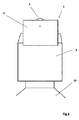
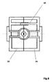
Figur 1 zeigt die Ansicht des Spenders 1 mit dem Dosierrad 2, dem Kolben 3, dem Verschluss 4 sowie den Tuben- oder Flaschenhals 10. -
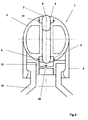
Figur 2 zeigt einen Querschnitt durch den Spender 1, das einstückige Dosierrad 2, welches mit den verankerten und eingeschnappten Einlass- und Auslassventilen 6 mit Austrittsöffnungen 7 und dem Kolben 8 als zylindrische Kolbenvariante dargestellt ist. Der Schnappverschluss 9, welcher das komplette Dosierrad aufnimmt. Im Tuben- oder Flaschenhals 10 ist das produktrichtungsweisende 20 Rücksaugventil 11 integriert. Ausserdem ist eine nicht näher gekennzeichnete Dosierkammer gezeigt, welche die Creme bzw das gelartige Produkt aufnehmen soll. -
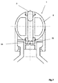
Figur 3 zeigt einen Querschnitt durch den Spender 1 als geschlossene Variante, d.h. der Kolben 8, welcher am Kolbendichtsitz 5 anliegt, ob kugelig oder zylindrisch läuft gegen die geschlitzte Austrittswandung 12 im Ein- oder Auslassventil 6. Die Schnappelemente 13 verankern das Auslassventil 6 mit dem Dosierrad 2. Im Flaschen- oder Tubenhals 10 ist ein geschlitztes Rücksaugventil 11 vorgesehen. Der Schlitz 14 ist hier gut zu erkennen. -
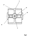
Figur 4 zeigt einen Horizontalschnitt im Bereich des Dosierrades 2 als T-Geometrie 17 das geschlitzte Ein- oder Auslassventil 6 mit der Schlitzung 12 sowie der Achsenlagerung 15 und Achse mit Verschlusswange 16. -
Figur 5 zeigt die Baugruppe 18, Dosierrad 2 mit Verschluss 9 im Querschnitt mit dem Kolben 3 im Dichtsitz 5. -
Figur 6 zeigt die Baugruppe 19 mit dem Flaschen- oder Tubenhals 10 und dem Rücksaugventil 11 als strömungsgerichtete Variante 20. -
Figur 7 zeigt einen Querschnitt durch den Spender 1 der offenen Variante 7 mit einem Abscher- Abdicht- und Einrastelement 21 für das Dosierrad 2 im Rücksaugventil 11 um beim Drehen des Dosierrades 2 den geförderten Produktstrang der Creme bzw. des gelartigen Produkts in der Dosierkammer abzuscheren. -
Figur 8 zeigt eine Variante im Horizontalschnitt, wobei das Dosierrad 2 aus zwei Schalen 22 und 23 aufgebaut ist. Die Schalen 22, 23 werden mit den Halbschalenverbindungselementen 24 zusammen gehalten. Bei dieser Version ist eine Trennung am äußeren Umfang des Dosierrades 2 sichtbar. -
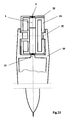
Figur 9 zeigt ein Ausführungsbeispiel im Längsschnitt durch die Tube mit dem im Tubenhals 10 integrierten Rücksaugventil 11. Das Dosierrad 2 ist mit den Schalen 22 und 23 sowie dem Kolben 3 und das Ein- und Auslassventil 6. -
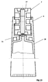
Figur 10 zeigtFigur 9 im Querschnitt durch den Tubenhals 10 mit der Dosierradverankerung 25 sowie das integrierte Rücksaugventil 11 im Tubenhals 10. Das Dosierrad 2 mit den beiden Schalen 22 und 23 und dem Ein- und Auslassventil 6 sowie den Kolben 3 in den Tubenhals 10 integriert. -
Figur 11 zeigt einen Querschnitt durch das Dosierrad 2 mit den beiden Schalen 22 und 23. -
Figur 12 zeigt einen Querschnitt durch eine Dosierradvariante mit den Schalen 22 und 23 mit einem konvexem Auslassventil 26 und kugelförmigem Kolben 3. Dabei ist der kugelförmige Kolben 3 nicht an sich kugelförmig, sondern weist abgerundete Endbereiche auf, die in der jeweiligen Position des Dosierrades 2 jeweils mit dem Ein- und Auslassventil 6 zusammenwirkt. Zusammenwirken bedeutet in diesem Zusammenhang, dass der kugelförmige Kolben 3 mit seinen abgerundeten Endbereichen fromschlüssig in das Ein- und Auslassventil 6 einfährt und die Creme bzw das gelartige Produkt aus der Dosierkammer in der Ausbringposition ausbringt.
Ausbringposition bedeutet dabei, dass das Dosierrad 2 mit dem Auslassventil weg von der Tube angeordnet ist und das Einlassventil zu der Tube hin angeordnet ist, wobei die Creme bzw das gelartige Produkt bereits in der Dosierkammer ist und durch den abgerundeten Kolben 3 aus dem Auslassventil gedrückt wird, wobei das Ein- und Auslassventil 6 schlitzförmig und damit nachgiebig ausgebildet ist, was gerade den Formschluss zwischen dem abgerundeten Kolben 3 und dem Einlass- und Auslassventil 6 ermöglicht. -
Figur 13 zeigt einen Querschnitt durch ein einstückiges Dosierrad 2 mit dem Endstück 27 sowie den Verschluss 4 und die Tube 10 mit montiertem Rücksaugventil 11. -
Figur 14 zeigt einen Querschnitt durch ein einstückiges Dosierrad 2 mit dem Ventilendstück 27 und den Verschluss 4, welcher für die Tube auch den Tubenhals 10 generiert. -
- 1
- Spender
- 2
- Dosierrad
- 3
- Kolben, kugelige Variante
- 4
- Verschluss
- 5
- Kolbendichtsitz
- 6
- Ein- oder Auslassventil
- 7
- Offene Variante
- 8
- Kolben, zylindrische Variante
- 9
- Schnappverschluss
- 10
- Tuben- oder Flaschenhals
- 11
- Rücksaugventil
- 12
- Schlitzung
- 13
- Schnappelemente
- 14
- Rücksaugventil, Variante geschlitzt
- 15
- Achsenlagerung
- 16
- Verschlusswange
- 17
- T-Geometrie
- 18
- Baugruppe Dosierrad
- 19
- Baugruppe Flaschenhals
- 20
- Rücksaugventil, richtungsweisend
- 21
- Abdicht- Abscher- und Einrastelement
- 22
- Erste Schale
- 23
- Zweite Schale
- 24
- Schalenverbindungselemente
- 25
- Dosierradverankerung
- 26
- Konvexes Auslassventil
- 27
- Endstück
Claims (7)
- Strangdosierer zum Ausbringen von Cremes oder gelartigen Produkten als ein Tubeninhalt aus einer Tube, wobei der Strangdosierer auf die Tube aufbringbar ist, wobei der Strangdosierer ein Dosierrad (1) umfasst, wobei das Dosierrad (1) eine Dosierkammer aufweist, wobei die Dosierkammer mit einem Kolben (3) zusammenwirkt, wobei das Dosierrad (1) an dem Strangdosierer drehbar angeordnet ist und der Strangdosierer ein Austrittsloch aufweist und der Strangdosierer ein Rücksaugventil (11, 14, 20) aufweist,
dadurch gekennzeichnet, dass
das Dosierrad (1) eine konkave Fingeraufnahme aufweist und einstückig ausgebildet ist, wobei die Dosierkammer verschlossen ist und ein Ein- und Auslassventil (6) aufweist, wobei das Ein- und Auslassventil (6) eine Schlitzung (12) ist, wobei das Dosierrad (1) aus einer ersten Schale (22) und einer zweiten Schale (23) besteht, wobei die erste Schale (22) und die zweite Schale (23) durch Schalenverbindungslemente miteinander verbunden sind, wobei das Rücksaugventil (11) in einem Tubenhals (10) angeordnet ist und ein Abdicht-Abscher- und Einrastelement im Tubenhals (10) umfasst ist. - Strangdosierer Nach Anspruch 1, dadurch gekennzeichnet, dass der Kolben (3) zylindrisch ist.
- Strangdosierer nach Anspruch 1 oder 2, dadurch gekennzeichnet, dass der Kolben (3) abgerundete Endbereiche aufweist.
- Strangdosierer nach einem der vorigen Ansprüche, gekennzeichnet durch ein konvexes Auslassventl (26) aufweist.
- Strangdosierer nach einem der vorigen Ansprüche, dadurch gekennzeichnet, dass das Dosierrad (2) zwei Einlass- und Auslassventile (6) aufweist.
- Strangdosierer nach einem der vorigen Ansprüche, dadurch gekennzeichnet, dass das vormontierte Dosierrad (2) drehbar in die Wangen eines Tuben- oder Flaschenverschlusses montierbar ist
- Strangdosierer nach Anspruich 6, dadurch gekennzeichnet, dass eine Drehachse des Tuben- oder Flaschenverschlusses in die Nabe des Dosierrades (2) einschnappbar ist.
Priority Applications (1)
| Application Number | Priority Date | Filing Date | Title |
|---|---|---|---|
| PL16181720T PL3127831T3 (pl) | 2015-08-03 | 2016-07-28 | Dozownik do wyprowadzania kremu |
Applications Claiming Priority (2)
| Application Number | Priority Date | Filing Date | Title |
|---|---|---|---|
| DE102015112725 | 2015-08-03 | ||
| DE102016112891.0A DE102016112891A1 (de) | 2015-08-03 | 2016-07-13 | Strangdosierer zum Ausbringen von Cremes |
Publications (2)
| Publication Number | Publication Date |
|---|---|
| EP3127831A1 true EP3127831A1 (de) | 2017-02-08 |
| EP3127831B1 EP3127831B1 (de) | 2019-02-27 |
Family
ID=56557550
Family Applications (1)
| Application Number | Title | Priority Date | Filing Date |
|---|---|---|---|
| EP16181720.0A Active EP3127831B1 (de) | 2015-08-03 | 2016-07-28 | Strangdosierer zum ausbringen von cremes |
Country Status (2)
| Country | Link |
|---|---|
| EP (1) | EP3127831B1 (de) |
| PL (1) | PL3127831T3 (de) |
Citations (4)
| Publication number | Priority date | Publication date | Assignee | Title |
|---|---|---|---|---|
| US3388839A (en) * | 1966-12-12 | 1968-06-18 | Donald V. Frydenberg | Metering dispenser with piston confined in a rotatable element |
| WO2003060435A1 (en) * | 2002-01-15 | 2003-07-24 | Jacobus Adriaan Wessels | Valve unit |
| WO2004092032A1 (en) * | 2003-04-17 | 2004-10-28 | Jacobus Adriaan Wessels | Closure arrangement |
| WO2014072418A1 (de) | 2012-11-07 | 2014-05-15 | Karl-Heinz Fuchs | Vorrichtung zum dosieren von cremes |
-
2016
- 2016-07-28 PL PL16181720T patent/PL3127831T3/pl unknown
- 2016-07-28 EP EP16181720.0A patent/EP3127831B1/de active Active
Patent Citations (4)
| Publication number | Priority date | Publication date | Assignee | Title |
|---|---|---|---|---|
| US3388839A (en) * | 1966-12-12 | 1968-06-18 | Donald V. Frydenberg | Metering dispenser with piston confined in a rotatable element |
| WO2003060435A1 (en) * | 2002-01-15 | 2003-07-24 | Jacobus Adriaan Wessels | Valve unit |
| WO2004092032A1 (en) * | 2003-04-17 | 2004-10-28 | Jacobus Adriaan Wessels | Closure arrangement |
| WO2014072418A1 (de) | 2012-11-07 | 2014-05-15 | Karl-Heinz Fuchs | Vorrichtung zum dosieren von cremes |
Also Published As
| Publication number | Publication date |
|---|---|
| PL3127831T3 (pl) | 2019-08-30 |
| EP3127831B1 (de) | 2019-02-27 |
Similar Documents
| Publication | Publication Date | Title |
|---|---|---|
| EP2613888B1 (de) | Dosiervorrichtung | |
| DE69720504T2 (de) | Abgabevorrichtung für ein zweikomponentiges fluid | |
| DE19729516C2 (de) | Pumpe zum dosierten Austragen von flüssigen, gelartigen oder viskosen Substanzen | |
| EP2200752B1 (de) | Dosierungsvorrichtung | |
| DE3425900C2 (de) | Vorrichtung mit Tropfenzähler zum Abgeben einer flüssigen oder pastösen Substanz | |
| EP1215167A2 (de) | Spenderausguss für fliessfähige Medien | |
| EP0073918B1 (de) | Auf Behälter aufsetzbare Pumpe | |
| DE102013218741B4 (de) | Spendersystem | |
| DE202011105790U1 (de) | Pumpeinrichtung für ein Behältnis für flüssige, pastöse oder aufschäumbare Hautreinigungs- und Pflegepräparate | |
| EP1332798A2 (de) | Spender für flüssige oder pastöse Produkte | |
| EP1344569A2 (de) | Spender für fliessfähige Produkte mit kugelförmig eingekapselten Bestandteilen | |
| DE602004005613T2 (de) | Pumpe zur abgabe eines fluidprodukts | |
| DE602005005514T2 (de) | Ein auslassventil und eine rückstellfeder für eine abgabevorrichtung bildendes flexibles teil | |
| EP3223960B1 (de) | Vorrichtung zum ausbringen eines flüssigen mediums | |
| EP4461419A1 (de) | Abgabekopf und spender | |
| DE1027945B (de) | Abgabeventil | |
| EP1091809B1 (de) | Applikations-vorrichtung für keimfreie fluide | |
| EP2917128B1 (de) | Vorrichtung zum dosieren von cremes | |
| EP1575710A1 (de) | Dosiervorrichtung | |
| EP3127831B1 (de) | Strangdosierer zum ausbringen von cremes | |
| EP3432951B1 (de) | Kartuschentropfendosierer | |
| DE102016112891A1 (de) | Strangdosierer zum Ausbringen von Cremes | |
| EP1177987B1 (de) | Behälter zur Mischung von zwei Komponenten | |
| EP2246122B1 (de) | Austragvorrichtung für flüssige oder pastöse Medien | |
| DE20312731U1 (de) | Spenderventil |
Legal Events
| Date | Code | Title | Description |
|---|---|---|---|
| PUAI | Public reference made under article 153(3) epc to a published international application that has entered the european phase |
Free format text: ORIGINAL CODE: 0009012 |
|
| STAA | Information on the status of an ep patent application or granted ep patent |
Free format text: STATUS: THE APPLICATION HAS BEEN PUBLISHED |
|
| AK | Designated contracting states |
Kind code of ref document: A1 Designated state(s): AL AT BE BG CH CY CZ DE DK EE ES FI FR GB GR HR HU IE IS IT LI LT LU LV MC MK MT NL NO PL PT RO RS SE SI SK SM TR |
|
| AX | Request for extension of the european patent |
Extension state: BA ME |
|
| STAA | Information on the status of an ep patent application or granted ep patent |
Free format text: STATUS: REQUEST FOR EXAMINATION WAS MADE |
|
| 17P | Request for examination filed |
Effective date: 20170725 |
|
| RBV | Designated contracting states (corrected) |
Designated state(s): AL AT BE BG CH CY CZ DE DK EE ES FI FR GB GR HR HU IE IS IT LI LT LU LV MC MK MT NL NO PL PT RO RS SE SI SK SM TR |
|
| STAA | Information on the status of an ep patent application or granted ep patent |
Free format text: STATUS: EXAMINATION IS IN PROGRESS |
|
| 17Q | First examination report despatched |
Effective date: 20171123 |
|
| GRAP | Despatch of communication of intention to grant a patent |
Free format text: ORIGINAL CODE: EPIDOSNIGR1 |
|
| STAA | Information on the status of an ep patent application or granted ep patent |
Free format text: STATUS: GRANT OF PATENT IS INTENDED |
|
| RIC1 | Information provided on ipc code assigned before grant |
Ipc: B65D 35/40 20060101AFI20180810BHEP Ipc: G01F 11/02 20060101ALI20180810BHEP |
|
| INTG | Intention to grant announced |
Effective date: 20180912 |
|
| GRAS | Grant fee paid |
Free format text: ORIGINAL CODE: EPIDOSNIGR3 |
|
| GRAA | (expected) grant |
Free format text: ORIGINAL CODE: 0009210 |
|
| STAA | Information on the status of an ep patent application or granted ep patent |
Free format text: STATUS: THE PATENT HAS BEEN GRANTED |
|
| AK | Designated contracting states |
Kind code of ref document: B1 Designated state(s): AL AT BE BG CH CY CZ DE DK EE ES FI FR GB GR HR HU IE IS IT LI LT LU LV MC MK MT NL NO PL PT RO RS SE SI SK SM TR |
|
| REG | Reference to a national code |
Ref country code: GB Ref legal event code: FG4D Free format text: NOT ENGLISH |
|
| REG | Reference to a national code |
Ref country code: CH Ref legal event code: EP |
|
| REG | Reference to a national code |
Ref country code: AT Ref legal event code: REF Ref document number: 1100957 Country of ref document: AT Kind code of ref document: T Effective date: 20190315 |
|
| REG | Reference to a national code |
Ref country code: IE Ref legal event code: FG4D Free format text: LANGUAGE OF EP DOCUMENT: GERMAN |
|
| REG | Reference to a national code |
Ref country code: DE Ref legal event code: R096 Ref document number: 502016003506 Country of ref document: DE |
|
| REG | Reference to a national code |
Ref country code: CH Ref legal event code: NV Representative=s name: ARIE WUBBEN C/O MEDIPACK AG, CH |
|
| REG | Reference to a national code |
Ref country code: NL Ref legal event code: MP Effective date: 20190227 |
|
| REG | Reference to a national code |
Ref country code: LT Ref legal event code: MG4D |
|
| PG25 | Lapsed in a contracting state [announced via postgrant information from national office to epo] |
Ref country code: NL Free format text: LAPSE BECAUSE OF FAILURE TO SUBMIT A TRANSLATION OF THE DESCRIPTION OR TO PAY THE FEE WITHIN THE PRESCRIBED TIME-LIMIT Effective date: 20190227 Ref country code: LT Free format text: LAPSE BECAUSE OF FAILURE TO SUBMIT A TRANSLATION OF THE DESCRIPTION OR TO PAY THE FEE WITHIN THE PRESCRIBED TIME-LIMIT Effective date: 20190227 Ref country code: FI Free format text: LAPSE BECAUSE OF FAILURE TO SUBMIT A TRANSLATION OF THE DESCRIPTION OR TO PAY THE FEE WITHIN THE PRESCRIBED TIME-LIMIT Effective date: 20190227 Ref country code: PT Free format text: LAPSE BECAUSE OF FAILURE TO SUBMIT A TRANSLATION OF THE DESCRIPTION OR TO PAY THE FEE WITHIN THE PRESCRIBED TIME-LIMIT Effective date: 20190627 Ref country code: SE Free format text: LAPSE BECAUSE OF FAILURE TO SUBMIT A TRANSLATION OF THE DESCRIPTION OR TO PAY THE FEE WITHIN THE PRESCRIBED TIME-LIMIT Effective date: 20190227 Ref country code: NO Free format text: LAPSE BECAUSE OF FAILURE TO SUBMIT A TRANSLATION OF THE DESCRIPTION OR TO PAY THE FEE WITHIN THE PRESCRIBED TIME-LIMIT Effective date: 20190527 |
|
| PG25 | Lapsed in a contracting state [announced via postgrant information from national office to epo] |
Ref country code: BG Free format text: LAPSE BECAUSE OF FAILURE TO SUBMIT A TRANSLATION OF THE DESCRIPTION OR TO PAY THE FEE WITHIN THE PRESCRIBED TIME-LIMIT Effective date: 20190527 Ref country code: GR Free format text: LAPSE BECAUSE OF FAILURE TO SUBMIT A TRANSLATION OF THE DESCRIPTION OR TO PAY THE FEE WITHIN THE PRESCRIBED TIME-LIMIT Effective date: 20190528 Ref country code: IS Free format text: LAPSE BECAUSE OF FAILURE TO SUBMIT A TRANSLATION OF THE DESCRIPTION OR TO PAY THE FEE WITHIN THE PRESCRIBED TIME-LIMIT Effective date: 20190627 Ref country code: LV Free format text: LAPSE BECAUSE OF FAILURE TO SUBMIT A TRANSLATION OF THE DESCRIPTION OR TO PAY THE FEE WITHIN THE PRESCRIBED TIME-LIMIT Effective date: 20190227 Ref country code: HR Free format text: LAPSE BECAUSE OF FAILURE TO SUBMIT A TRANSLATION OF THE DESCRIPTION OR TO PAY THE FEE WITHIN THE PRESCRIBED TIME-LIMIT Effective date: 20190227 Ref country code: RS Free format text: LAPSE BECAUSE OF FAILURE TO SUBMIT A TRANSLATION OF THE DESCRIPTION OR TO PAY THE FEE WITHIN THE PRESCRIBED TIME-LIMIT Effective date: 20190227 |
|
| REG | Reference to a national code |
Ref country code: ES Ref legal event code: FG2A Ref document number: 2726881 Country of ref document: ES Kind code of ref document: T3 Effective date: 20191010 |
|
| PG25 | Lapsed in a contracting state [announced via postgrant information from national office to epo] |
Ref country code: CZ Free format text: LAPSE BECAUSE OF FAILURE TO SUBMIT A TRANSLATION OF THE DESCRIPTION OR TO PAY THE FEE WITHIN THE PRESCRIBED TIME-LIMIT Effective date: 20190227 Ref country code: RO Free format text: LAPSE BECAUSE OF FAILURE TO SUBMIT A TRANSLATION OF THE DESCRIPTION OR TO PAY THE FEE WITHIN THE PRESCRIBED TIME-LIMIT Effective date: 20190227 Ref country code: SK Free format text: LAPSE BECAUSE OF FAILURE TO SUBMIT A TRANSLATION OF THE DESCRIPTION OR TO PAY THE FEE WITHIN THE PRESCRIBED TIME-LIMIT Effective date: 20190227 Ref country code: EE Free format text: LAPSE BECAUSE OF FAILURE TO SUBMIT A TRANSLATION OF THE DESCRIPTION OR TO PAY THE FEE WITHIN THE PRESCRIBED TIME-LIMIT Effective date: 20190227 Ref country code: AL Free format text: LAPSE BECAUSE OF FAILURE TO SUBMIT A TRANSLATION OF THE DESCRIPTION OR TO PAY THE FEE WITHIN THE PRESCRIBED TIME-LIMIT Effective date: 20190227 Ref country code: DK Free format text: LAPSE BECAUSE OF FAILURE TO SUBMIT A TRANSLATION OF THE DESCRIPTION OR TO PAY THE FEE WITHIN THE PRESCRIBED TIME-LIMIT Effective date: 20190227 |
|
| REG | Reference to a national code |
Ref country code: DE Ref legal event code: R097 Ref document number: 502016003506 Country of ref document: DE |
|
| PG25 | Lapsed in a contracting state [announced via postgrant information from national office to epo] |
Ref country code: SM Free format text: LAPSE BECAUSE OF FAILURE TO SUBMIT A TRANSLATION OF THE DESCRIPTION OR TO PAY THE FEE WITHIN THE PRESCRIBED TIME-LIMIT Effective date: 20190227 |
|
| PLBE | No opposition filed within time limit |
Free format text: ORIGINAL CODE: 0009261 |
|
| STAA | Information on the status of an ep patent application or granted ep patent |
Free format text: STATUS: NO OPPOSITION FILED WITHIN TIME LIMIT |
|
| 26N | No opposition filed |
Effective date: 20191128 |
|
| PG25 | Lapsed in a contracting state [announced via postgrant information from national office to epo] |
Ref country code: SI Free format text: LAPSE BECAUSE OF FAILURE TO SUBMIT A TRANSLATION OF THE DESCRIPTION OR TO PAY THE FEE WITHIN THE PRESCRIBED TIME-LIMIT Effective date: 20190227 Ref country code: MC Free format text: LAPSE BECAUSE OF FAILURE TO SUBMIT A TRANSLATION OF THE DESCRIPTION OR TO PAY THE FEE WITHIN THE PRESCRIBED TIME-LIMIT Effective date: 20190227 |
|
| PG25 | Lapsed in a contracting state [announced via postgrant information from national office to epo] |
Ref country code: TR Free format text: LAPSE BECAUSE OF FAILURE TO SUBMIT A TRANSLATION OF THE DESCRIPTION OR TO PAY THE FEE WITHIN THE PRESCRIBED TIME-LIMIT Effective date: 20190227 |
|
| REG | Reference to a national code |
Ref country code: BE Ref legal event code: MM Effective date: 20190731 |
|
| PG25 | Lapsed in a contracting state [announced via postgrant information from national office to epo] |
Ref country code: LU Free format text: LAPSE BECAUSE OF NON-PAYMENT OF DUE FEES Effective date: 20190728 Ref country code: BE Free format text: LAPSE BECAUSE OF NON-PAYMENT OF DUE FEES Effective date: 20190731 |
|
| PG25 | Lapsed in a contracting state [announced via postgrant information from national office to epo] |
Ref country code: IE Free format text: LAPSE BECAUSE OF NON-PAYMENT OF DUE FEES Effective date: 20190728 |
|
| PG25 | Lapsed in a contracting state [announced via postgrant information from national office to epo] |
Ref country code: CY Free format text: LAPSE BECAUSE OF FAILURE TO SUBMIT A TRANSLATION OF THE DESCRIPTION OR TO PAY THE FEE WITHIN THE PRESCRIBED TIME-LIMIT Effective date: 20190227 |
|
| PG25 | Lapsed in a contracting state [announced via postgrant information from national office to epo] |
Ref country code: HU Free format text: LAPSE BECAUSE OF FAILURE TO SUBMIT A TRANSLATION OF THE DESCRIPTION OR TO PAY THE FEE WITHIN THE PRESCRIBED TIME-LIMIT; INVALID AB INITIO Effective date: 20160728 Ref country code: MT Free format text: LAPSE BECAUSE OF FAILURE TO SUBMIT A TRANSLATION OF THE DESCRIPTION OR TO PAY THE FEE WITHIN THE PRESCRIBED TIME-LIMIT Effective date: 20190227 |
|
| PG25 | Lapsed in a contracting state [announced via postgrant information from national office to epo] |
Ref country code: MK Free format text: LAPSE BECAUSE OF FAILURE TO SUBMIT A TRANSLATION OF THE DESCRIPTION OR TO PAY THE FEE WITHIN THE PRESCRIBED TIME-LIMIT Effective date: 20190227 |
|
| REG | Reference to a national code |
Ref country code: AT Ref legal event code: MM01 Ref document number: 1100957 Country of ref document: AT Kind code of ref document: T Effective date: 20210728 |
|
| PG25 | Lapsed in a contracting state [announced via postgrant information from national office to epo] |
Ref country code: AT Free format text: LAPSE BECAUSE OF NON-PAYMENT OF DUE FEES Effective date: 20210728 |
|
| PGFP | Annual fee paid to national office [announced via postgrant information from national office to epo] |
Ref country code: ES Payment date: 20250819 Year of fee payment: 10 |
|
| PGFP | Annual fee paid to national office [announced via postgrant information from national office to epo] |
Ref country code: DE Payment date: 20250926 Year of fee payment: 10 |
|
| PGFP | Annual fee paid to national office [announced via postgrant information from national office to epo] |
Ref country code: IT Payment date: 20250731 Year of fee payment: 10 Ref country code: PL Payment date: 20250721 Year of fee payment: 10 |
|
| PGFP | Annual fee paid to national office [announced via postgrant information from national office to epo] |
Ref country code: GB Payment date: 20250724 Year of fee payment: 10 |
|
| PGFP | Annual fee paid to national office [announced via postgrant information from national office to epo] |
Ref country code: FR Payment date: 20250723 Year of fee payment: 10 |
|
| PGFP | Annual fee paid to national office [announced via postgrant information from national office to epo] |
Ref country code: CH Payment date: 20250801 Year of fee payment: 10 |