EP3127873A1 - Spiralpumpe, vorrichtung und verfahren zur wasserbehandlung - Google Patents
Spiralpumpe, vorrichtung und verfahren zur wasserbehandlung Download PDFInfo
- Publication number
- EP3127873A1 EP3127873A1 EP16182330.7A EP16182330A EP3127873A1 EP 3127873 A1 EP3127873 A1 EP 3127873A1 EP 16182330 A EP16182330 A EP 16182330A EP 3127873 A1 EP3127873 A1 EP 3127873A1
- Authority
- EP
- European Patent Office
- Prior art keywords
- spiral
- pump
- housing
- pump body
- water
- Prior art date
- Legal status (The legal status is an assumption and is not a legal conclusion. Google has not performed a legal analysis and makes no representation as to the accuracy of the status listed.)
- Granted
Links
- XLYOFNOQVPJJNP-UHFFFAOYSA-N water Substances O XLYOFNOQVPJJNP-UHFFFAOYSA-N 0.000 title claims abstract description 118
- 238000000034 method Methods 0.000 title claims abstract description 13
- 239000007789 gas Substances 0.000 claims description 57
- QVGXLLKOCUKJST-UHFFFAOYSA-N atomic oxygen Chemical compound [O] QVGXLLKOCUKJST-UHFFFAOYSA-N 0.000 claims description 9
- 239000001301 oxygen Substances 0.000 claims description 9
- 229910052760 oxygen Inorganic materials 0.000 claims description 9
- 238000005086 pumping Methods 0.000 claims description 3
- 230000008878 coupling Effects 0.000 claims description 2
- 238000010168 coupling process Methods 0.000 claims description 2
- 238000005859 coupling reaction Methods 0.000 claims description 2
- 230000008901 benefit Effects 0.000 description 7
- 241000894006 Bacteria Species 0.000 description 5
- 239000000126 substance Substances 0.000 description 5
- 241000251468 Actinopterygii Species 0.000 description 4
- 230000033001 locomotion Effects 0.000 description 4
- IJGRMHOSHXDMSA-UHFFFAOYSA-N Atomic nitrogen Chemical compound N#N IJGRMHOSHXDMSA-UHFFFAOYSA-N 0.000 description 3
- 239000002028 Biomass Substances 0.000 description 3
- 241001148470 aerobic bacillus Species 0.000 description 3
- 229910001873 dinitrogen Inorganic materials 0.000 description 3
- 238000005728 strengthening Methods 0.000 description 3
- QGZKDVFQNNGYKY-UHFFFAOYSA-N Ammonia Chemical compound N QGZKDVFQNNGYKY-UHFFFAOYSA-N 0.000 description 2
- 239000004743 Polypropylene Substances 0.000 description 2
- 230000002411 adverse Effects 0.000 description 2
- 238000005273 aeration Methods 0.000 description 2
- 238000004140 cleaning Methods 0.000 description 2
- 230000000694 effects Effects 0.000 description 2
- 238000001914 filtration Methods 0.000 description 2
- 238000005192 partition Methods 0.000 description 2
- 239000004033 plastic Substances 0.000 description 2
- 229920003023 plastic Polymers 0.000 description 2
- 229920001155 polypropylene Polymers 0.000 description 2
- 239000007787 solid Substances 0.000 description 2
- 101100129500 Caenorhabditis elegans max-2 gene Proteins 0.000 description 1
- 241000195493 Cryptophyta Species 0.000 description 1
- 230000009471 action Effects 0.000 description 1
- 229910021529 ammonia Inorganic materials 0.000 description 1
- 230000015572 biosynthetic process Effects 0.000 description 1
- 238000009395 breeding Methods 0.000 description 1
- 230000001488 breeding effect Effects 0.000 description 1
- 230000005587 bubbling Effects 0.000 description 1
- 230000000593 degrading effect Effects 0.000 description 1
- 210000003608 fece Anatomy 0.000 description 1
- 230000036541 health Effects 0.000 description 1
- 230000001788 irregular Effects 0.000 description 1
- 239000007788 liquid Substances 0.000 description 1
- 238000012423 maintenance Methods 0.000 description 1
- 238000012986 modification Methods 0.000 description 1
- 230000004048 modification Effects 0.000 description 1
- 150000002823 nitrates Chemical class 0.000 description 1
- 150000002894 organic compounds Chemical class 0.000 description 1
- -1 polypropylene Polymers 0.000 description 1
- 239000004800 polyvinyl chloride Substances 0.000 description 1
- 230000009467 reduction Effects 0.000 description 1
- 238000007665 sagging Methods 0.000 description 1
- 241001148471 unidentified anaerobic bacterium Species 0.000 description 1
Images


Classifications
-
- C—CHEMISTRY; METALLURGY
- C02—TREATMENT OF WATER, WASTE WATER, SEWAGE, OR SLUDGE
- C02F—TREATMENT OF WATER, WASTE WATER, SEWAGE, OR SLUDGE
- C02F3/00—Biological treatment of water, waste water, or sewage
- C02F3/02—Aerobic processes
- C02F3/08—Aerobic processes using moving contact bodies
- C02F3/082—Rotating biological contactors
-
- F—MECHANICAL ENGINEERING; LIGHTING; HEATING; WEAPONS; BLASTING
- F04—POSITIVE - DISPLACEMENT MACHINES FOR LIQUIDS; PUMPS FOR LIQUIDS OR ELASTIC FLUIDS
- F04D—NON-POSITIVE-DISPLACEMENT PUMPS
- F04D29/00—Details, component parts, or accessories
- F04D29/18—Rotors
- F04D29/22—Rotors specially for centrifugal pumps
- F04D29/2238—Special flow patterns
- F04D29/225—Channel wheels, e.g. one blade or one flow channel
-
- A—HUMAN NECESSITIES
- A01—AGRICULTURE; FORESTRY; ANIMAL HUSBANDRY; HUNTING; TRAPPING; FISHING
- A01K—ANIMAL HUSBANDRY; AVICULTURE; APICULTURE; PISCICULTURE; FISHING; REARING OR BREEDING ANIMALS, NOT OTHERWISE PROVIDED FOR; NEW BREEDS OF ANIMALS
- A01K63/00—Receptacles for live fish, e.g. aquaria; Terraria
- A01K63/04—Arrangements for treating water specially adapted to receptacles for live fish
-
- A—HUMAN NECESSITIES
- A01—AGRICULTURE; FORESTRY; ANIMAL HUSBANDRY; HUNTING; TRAPPING; FISHING
- A01K—ANIMAL HUSBANDRY; AVICULTURE; APICULTURE; PISCICULTURE; FISHING; REARING OR BREEDING ANIMALS, NOT OTHERWISE PROVIDED FOR; NEW BREEDS OF ANIMALS
- A01K63/00—Receptacles for live fish, e.g. aquaria; Terraria
- A01K63/04—Arrangements for treating water specially adapted to receptacles for live fish
- A01K63/042—Introducing gases into the water, e.g. aerators, air pumps
-
- C—CHEMISTRY; METALLURGY
- C02—TREATMENT OF WATER, WASTE WATER, SEWAGE, OR SLUDGE
- C02F—TREATMENT OF WATER, WASTE WATER, SEWAGE, OR SLUDGE
- C02F3/00—Biological treatment of water, waste water, or sewage
- C02F3/02—Aerobic processes
-
- F—MECHANICAL ENGINEERING; LIGHTING; HEATING; WEAPONS; BLASTING
- F04—POSITIVE - DISPLACEMENT MACHINES FOR LIQUIDS; PUMPS FOR LIQUIDS OR ELASTIC FLUIDS
- F04C—ROTARY-PISTON, OR OSCILLATING-PISTON, POSITIVE-DISPLACEMENT MACHINES FOR LIQUIDS; ROTARY-PISTON, OR OSCILLATING-PISTON, POSITIVE-DISPLACEMENT PUMPS
- F04C15/00—Component parts, details or accessories of machines, pumps or pumping installations, not provided for in groups F04C2/00 - F04C14/00
- F04C15/06—Arrangements for admission or discharge of the working fluid, e.g. constructional features of the inlet or outlet
-
- F—MECHANICAL ENGINEERING; LIGHTING; HEATING; WEAPONS; BLASTING
- F04—POSITIVE - DISPLACEMENT MACHINES FOR LIQUIDS; PUMPS FOR LIQUIDS OR ELASTIC FLUIDS
- F04C—ROTARY-PISTON, OR OSCILLATING-PISTON, POSITIVE-DISPLACEMENT MACHINES FOR LIQUIDS; ROTARY-PISTON, OR OSCILLATING-PISTON, POSITIVE-DISPLACEMENT PUMPS
- F04C2/00—Rotary-piston machines or pumps
- F04C2/02—Rotary-piston machines or pumps of arcuate-engagement type, i.e. with circular translatory movement of co-operating members, each member having the same number of teeth or tooth-equivalents
- F04C2/025—Rotary-piston machines or pumps of arcuate-engagement type, i.e. with circular translatory movement of co-operating members, each member having the same number of teeth or tooth-equivalents the moving and the stationary member having co-operating elements in spiral form
-
- F—MECHANICAL ENGINEERING; LIGHTING; HEATING; WEAPONS; BLASTING
- F04—POSITIVE - DISPLACEMENT MACHINES FOR LIQUIDS; PUMPS FOR LIQUIDS OR ELASTIC FLUIDS
- F04D—NON-POSITIVE-DISPLACEMENT PUMPS
- F04D15/00—Control, e.g. regulation, of pumps, pumping installations or systems
- F04D15/0027—Varying behaviour or the very pump
- F04D15/0044—Varying behaviour or the very pump by introducing a gas
-
- F—MECHANICAL ENGINEERING; LIGHTING; HEATING; WEAPONS; BLASTING
- F04—POSITIVE - DISPLACEMENT MACHINES FOR LIQUIDS; PUMPS FOR LIQUIDS OR ELASTIC FLUIDS
- F04D—NON-POSITIVE-DISPLACEMENT PUMPS
- F04D29/00—Details, component parts, or accessories
- F04D29/18—Rotors
- F04D29/22—Rotors specially for centrifugal pumps
- F04D29/24—Vanes
- F04D29/242—Geometry, shape
- F04D29/245—Geometry, shape for special effects
-
- F—MECHANICAL ENGINEERING; LIGHTING; HEATING; WEAPONS; BLASTING
- F04—POSITIVE - DISPLACEMENT MACHINES FOR LIQUIDS; PUMPS FOR LIQUIDS OR ELASTIC FLUIDS
- F04D—NON-POSITIVE-DISPLACEMENT PUMPS
- F04D29/00—Details, component parts, or accessories
- F04D29/40—Casings; Connections of working fluid
- F04D29/42—Casings; Connections of working fluid for radial or helico-centrifugal pumps
- F04D29/426—Casings; Connections of working fluid for radial or helico-centrifugal pumps especially adapted for liquid pumps
-
- C—CHEMISTRY; METALLURGY
- C02—TREATMENT OF WATER, WASTE WATER, SEWAGE, OR SLUDGE
- C02F—TREATMENT OF WATER, WASTE WATER, SEWAGE, OR SLUDGE
- C02F2103/00—Nature of the water, waste water, sewage or sludge to be treated
- C02F2103/22—Nature of the water, waste water, sewage or sludge to be treated from the processing of animals, e.g. poultry, fish, or parts thereof
-
- C—CHEMISTRY; METALLURGY
- C02—TREATMENT OF WATER, WASTE WATER, SEWAGE, OR SLUDGE
- C02F—TREATMENT OF WATER, WASTE WATER, SEWAGE, OR SLUDGE
- C02F2301/00—General aspects of water treatment
- C02F2301/02—Fluid flow conditions
- C02F2301/026—Spiral, helicoidal, radial
-
- C—CHEMISTRY; METALLURGY
- C02—TREATMENT OF WATER, WASTE WATER, SEWAGE, OR SLUDGE
- C02F—TREATMENT OF WATER, WASTE WATER, SEWAGE, OR SLUDGE
- C02F2301/00—General aspects of water treatment
- C02F2301/06—Pressure conditions
- C02F2301/066—Overpressure, high pressure
-
- C—CHEMISTRY; METALLURGY
- C02—TREATMENT OF WATER, WASTE WATER, SEWAGE, OR SLUDGE
- C02F—TREATMENT OF WATER, WASTE WATER, SEWAGE, OR SLUDGE
- C02F2303/00—Specific treatment goals
- C02F2303/02—Odour removal or prevention of malodour
-
- F—MECHANICAL ENGINEERING; LIGHTING; HEATING; WEAPONS; BLASTING
- F04—POSITIVE - DISPLACEMENT MACHINES FOR LIQUIDS; PUMPS FOR LIQUIDS OR ELASTIC FLUIDS
- F04C—ROTARY-PISTON, OR OSCILLATING-PISTON, POSITIVE-DISPLACEMENT MACHINES FOR LIQUIDS; ROTARY-PISTON, OR OSCILLATING-PISTON, POSITIVE-DISPLACEMENT PUMPS
- F04C2210/00—Fluid
- F04C2210/24—Fluid mixed, e.g. two-phase fluid
-
- Y—GENERAL TAGGING OF NEW TECHNOLOGICAL DEVELOPMENTS; GENERAL TAGGING OF CROSS-SECTIONAL TECHNOLOGIES SPANNING OVER SEVERAL SECTIONS OF THE IPC; TECHNICAL SUBJECTS COVERED BY FORMER USPC CROSS-REFERENCE ART COLLECTIONS [XRACs] AND DIGESTS
- Y02—TECHNOLOGIES OR APPLICATIONS FOR MITIGATION OR ADAPTATION AGAINST CLIMATE CHANGE
- Y02W—CLIMATE CHANGE MITIGATION TECHNOLOGIES RELATED TO WASTEWATER TREATMENT OR WASTE MANAGEMENT
- Y02W10/00—Technologies for wastewater treatment
- Y02W10/10—Biological treatment of water, waste water, or sewage
Definitions
- the invention relates to a spiral pump and a device for treating water comprising this spiral pump.
- Solids such as excreta of fish, leaves and filamentous algae, can be removed from the water with a mechanical filter.
- the water can however also comprise dissolved substances which have an adverse effect on the water quality. Examples of such substances are dissolved organic compounds such as ammonia or nitrates.
- dissolved organic compounds such as ammonia or nitrates.
- the removal or degrading down of the dissolved substances is essential to the health of the fish. An unpleasant odour can in addition be prevented or at least reduced.
- the spiral pump comprises a rotatable body with a number of coiled tubes. Water and air are taken up alternately into the tubes by rotating the body. This enhances the growth of aerobic bacteria in the tubes. The aerobic bacteria then degrade the harmful substances in the water.
- a drawback of such a conventional spiral pump for biological treatment is that the aeration of the water takes place in uncontrolled manner.
- the water is set into motion by the rotation of the spiral pump so that an alternating quantity of air and water is taken in each time.
- the growth of bacteria hereby takes place in uncontrolled manner, wherein optimal conditions are not usually created for the growth of the bacteria.
- An object of the invention is to obviate or at least reduce one or more of the above drawbacks and to provide an improved spiral pump, in particular for treating water.
- spiral pump according to the invention comprising:
- the device for instance comprises a drive, such as an electric motor, for rotating the pump body.
- a drive such as an electric motor
- the pressure in the housing can be controlled by means of the pressure chamber.
- the water level can be set by controlling the pressure.
- the water level is hereby more constant and a drive for rotating the pump body is thus loaded in a more uniform manner, this reducing wear to the drive.
- the efficiency of the spiral pump is moreover increased.
- a biofilm is for instance prevented from detaching from the wall of the channels of the spiral pump because of irregular movement of the water.
- the water level is preferably set at the height of the rotation axis so that about half the pump body is always situated in the water.
- the water level in the exit of the spiral pump is preferably also set at the height of the rotation axis by adjusting the pressure in the pressure chamber, i.e. the exit is half filled with water.
- the air on the exit side will seek a path through the water, which results in the formation of air bubbles and an associated bubbling sound. Air and water are however separated on the exit side by half submerging the exit under water using the pressure chamber, so that no, or in any case fewer, air bubbles occur. This prevents noise nuisance. Because bubbles are not formed, or hardly so, on the outlet side, the spiral pump is moreover more energy-efficient than conventional spiral pumps.
- the use of a pressure chamber further makes it possible to control the gas composition of the gas present in the housing.
- the pressure chamber in addition makes it possible to place the spiral pump below the water level of a basin of water for treating without this adversely affecting the operation of the spiral pump.
- the above stated axis around which the pump body rotates is defined as an axis which coincides with a central longitudinal axis of the approximately cylindrical pump body.
- a physical shaft will usually be provided in practice for rotating the pump body.
- the pump body can be fixedly connected to the physical shaft for combined rotation of the shaft and the pump body, or conversely be arranged for rotation around the shaft.
- the spiral pump according to the invention can be applied for biological treatment of water.
- Another possible application of the spiral pump according to the invention is however to pump liquids, in particular water.
- the advantage of a reduced wear to the drive is also gained in this application.
- the spiral pump further comprises means for controlling a gas pressure in the housing, the means comprising a gas feed, wherein the gas feed preferably comprises a pump.
- the water level can be set and/or adjusted by controlling the gas pressure.
- the means for controlling the gas pressure in the housing are preferably configured to set the water level in the housing to a level at the height of the axis of the pump body.
- the pump body will thus always be situated roughly half in the water so that equal volumes of air and water are taken in at a time during use.
- the water can if desired be set to a different level by controlling the pressure.
- the ratio of the volume of water and air taken in can in this way be adjusted.
- the gas feed preferably comprises a pump which supplies a gas such as air continuously.
- the oxygen content in the pressure chamber is held constant. This is because the biofilm consumes oxygen from the air present in the housing.
- the housing comprises an entry chamber which comprises the inlet and an exit chamber which is separated from the entry chamber and into which the outlet of the pump body debouches, wherein the gas feed is connected to the exit chamber for the purpose of pumping gas into the exit chamber, the housing further comprising a first conduit, of which a first outer end is positioned in the exit chamber at the height of the axis of the pump body and a second outer end is positioned in the entry chamber, and a second conduit, of which a first outer end is positioned in the entry chamber at the height of the axis of the pump body and a second outer end is positioned outside the housing.
- the water level is controlled with mechanical means, i.e. an electronic controller is not necessary.
- an electronic control can be provided, the device for instance comprising a level sensor which is configured to measure a water level in the housing and a controller which is configured to control the gas feed on the basis of the water level measured by the level sensor for the purpose of setting the water level in the housing.
- the device optionally further comprises a valve which is preferably also controlled by the controller.
- a desired water level is set using the controller.
- the controller can control the gas feed in order to increase the gas pressure in the housing so that the water level falls.
- a gas such as air is for instance pumped into the housing for this purpose.
- the controller can switch off the gas feed and open the valve in order to decrease the gas pressure in the housing so that the water level rises.
- the gas can alternatively be pumped out of the housing in order to thus reduce the pressure and allow the water level to rise.
- means are further provided for setting the gas composition in the pressure chamber.
- the means for setting the gas composition comprise for instance a gas feed which is provided on the housing and a controller which is connected to the gas feed and a sensor for measuring the concentration of a determined gas, wherein the controller is configured to control the gas feed on the basis of the measured concentration.
- the gas feed for instance comprises a valve which is opened and closed by the controller on the basis of the measured concentration.
- the means for setting the gas composition comprise a gas feed which carries a gas of the desired gas composition into the housing.
- the means for setting the gas composition can if desired be combined with the means for setting the water level.
- One controller is for instance provided which controls the gas pressure in the housing as well as the gas composition in the housing.
- the gas pressure is controlled by means of the above described mechanical control wherein the gas feed is configured to supply gas of the desired gas composition.
- the means for setting the gas composition preferably comprise means for setting the oxygen level in the pressure chamber.
- the growth of aerobic bacteria can be stimulated by controlling the oxygen level, for instance increasing the oxygen level relative to the outside air.
- the oxygen level is reduced, for instance by introducing nitrogen gas into the housing, in order to stimulate the growth of anaerobic bacteria and/or for denitrification of the water.
- the gas feed for instance supplies nitrogen gas with which both the pressure in the housing and the gas composition in the housing are set.
- the at least one spiral channel of the pump is for instance formed by means of at least one spiral tube.
- the pump body however comprises at least one sheet-like wall which is wound into a spiral and which defines the at least one spiral channel.
- the walls are of plastic.
- the walls are for instance of polypropylene (PP) or polyvinyl chloride (PVC). Practical tests have shown that plastic walls allow a sufficient measure of growth of biofilm while preventing the creation of too dense a biomass whereby the device becomes clogged.
- the pump body comprises a plurality of spiral channels, wherein a first outer end of each channel is located on an outer side of the pump body and forms an entrance opening, and a second outer end of each channel debouches into the outlet close to the axis.
- Providing a plurality of channels, i.e. a plurality of pump passageways, increases the lift of the pump and the efficiency of the spiral pump.
- the entrance openings of the spiral channels are distributed uniformly over the outer side of the pump body. Particularly the distance between adjacent entrance openings is preferably substantially equal.
- the pump body preferably comprises a plurality of sheet-like walls which are wound into a spiral and provided at a distance from each other so that a plurality of spiral channels are formed between the walls, wherein a first outer end of each channel is located on an outer side of the pump body and forms an entrance opening, and a second outer end of each channel debouches into the outlet close to the axis.
- the entrance openings of the spiral channels are distributed uniformly over the outer side of the pump body.
- the walls have substantially the same form and are rotated in each case through the same predetermined angle relative to each other.
- the angle can be determined by dividing 360 degrees by the number of walls. In an example with six walls and six entrance openings, the walls are rotated through an angle of 60 degrees relative to each other. The entrance openings are thus also 60 degrees removed from each other.
- a cover which forms a side wall of the at least one channel defined by the at least one sheet-like wall wound into a spiral.
- the covers preferably support on either side the walls wound into a spiral.
- the covers are for instance embodied as discs fitting onto the end surfaces of the substantially cylindrical pump body.
- the at least one channel has a diameter increasing from the entrance openings in the direction of the axis.
- a biofilm forms on the side walls of the channels.
- the growth of this biofilm is in itself desirable in the context of the biological treatment of the water.
- too strong a growth of biofilm can result in blockage in the channel.
- a part of the biofilm will for instance occasionally be detached by the flowing water and be carried along with the water. In conventional devices this usually results in blockages. This has the result that the device has to be shut down and cleaned. Because the biomass is removed during the cleaning, it will then take some time before sufficient biomass is available again as breeding ground for the bacteria for cleaning the water. This makes conventional devices for treating water relatively inefficient and maintenance-intensive.
- the detached biofilm is prevented from causing a blockage further along in the channel.
- the spiral pump is therefore less likely to become blocked than conventional devices and requires less maintenance.
- the at least one channel follows a Fermat spiral. That is, the one or more channels can each be described as a part of a Fermat spiral.
- the walls are preferably rotated 120 degrees relative to each other.
- r 1 a * ⁇ ⁇ 1 with ⁇ min ⁇ ⁇ 1 ⁇ ⁇ max
- r 2 a * ⁇ ⁇ 2 + 2 ⁇ / 3 with ⁇ min ⁇ 2 ⁇ / 3 ⁇ ⁇ 2 ⁇ ⁇ max ⁇ 2 ⁇ / 3
- r 3 a * ⁇ ⁇ 3 + 4 ⁇ / 3 with ⁇ min ⁇ 4 ⁇ / 3 ⁇ ⁇ 3 ⁇ ⁇ max ⁇ 4 ⁇ / 3
- (r 1 , ⁇ 1 ) represent respectively the radius and angle of the first wall
- (r 2 , ⁇ 2 ) represent respectively the radius and angle of the second wall
- (r 3 ⁇ 3 ) respectively the radius and angle of the third wall.
- the spiral pump further comprises means for controlling the inflow speed of water into the inlet which are configured to adjust the inflow speed to 0.1 - 10 m/s, preferably 0.5 - 5 m/s and most preferably 1-3 m/s.
- the invention further relates to a device for biological treatment of water comprising the spiral pump as described above.
- the invention further relates to a method for providing a spiral pump.
- the method comprises the following steps of:
- the method preferably comprises of providing a spiral pump as described above.
- the device for biological treatment of water and the method according to the invention have the same advantages and effects as described above for the spiral pump.
- the method preferably comprises of providing a gas with a pressure which differs from atmospheric pressure. In other words, a pressure greater than 1 bar prevails in the housing.
- the method comprises of coupling the inlet of the housing to a basin with water to be treated and setting a desired water level in the housing by controlling the gas pressure in the pressure chamber, wherein the desired water level differs from the water level in the basin.
- the gas pressure in the housing is for instance set above atmospheric pressure so that the spiral pump can be placed below the water level of the basin without the whole housing filling with water because of the water column on the entry side.
- This has the advantage that the spiral pump can be concealed underground without this affecting the operation of the spiral pump. In addition to an aesthetic advantage, this also has the advantage of reducing noise. Concealing the spiral pump is particularly relevant in the case of a pond, such as a pond for ornamental fish.
- the method further comprises of controlling the gas composition in the pressure chamber, and preferably controlling the oxygen content, for instance by supplying nitrogen gas.
- the invention further relates to an alternative spiral pump which corresponds to the above described embodiment of the spiral pump in which the at least one channel has a diameter increasing from the entrance openings in the direction of the axis, with the difference that the housing is not embodied as pressure chamber.
- the pressure chamber is optional.
- the alternative spiral pump comprises:
- the pump body comprises at least one sheet-like wall which is wound into a spiral and which defines the at least one spiral channel.
- the pump body comprises a number of sheet-like walls which are wound into a spiral and provided at a distance from each other so that a plurality of spiral channels are formed between the walls, wherein a first outer end of each channel is located on an outer side of the pump body and forms an entrance opening, and a second outer end of each channel debouches into the outlet close to the axis.
- the entrance openings are distributed uniformly over the outer side of the pump body.
- the walls have substantially the same form and are rotated in each case through the same predetermined angle relative to each other.
- the at least one channel follows for instance a Fermat spiral.
- the spiral pump comprises means for controlling the inflow speed of water into the inlet which are configured to adjust the inflow speed to 0.1 - 10 m/s.
- the invention also relates to a device for biological treatment of water comprising the alternative spiral pump as described above.
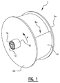
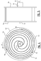
- pump body 2 ( figures 1 and 2 ) comprises three sheet-like walls 4a, 4b, 4c which extend in spiral form. Walls 4a, 4b and 4c are provided at a distance from each other, wherein the spiral forms are interleaved such that three spiral channels are formed between the walls. Covers 6a, 6b in the shape of discs are arranged on either side of the pump body. Discs 6a, 6b form the side walls of the spiral channels between walls 4a, 4b and 4c. Walls 4a, 4b, 4c are for instance welded along their whole length to discs 6a, 6b.
- Each channel has an outer end which is located on the outer side of pump body 2 and there forms an entrance opening 8a, 8b, 8c.
- the three entrance openings 8a, 8b, 8c are distributed uniformly over the outer wall.
- the angle between two adjacent entrance openings is in each case 120 degrees.
- pump body 2 Situated on a rear side of pump body 2a is an outlet 10.
- the channels defined between walls 4a, 4b, 4c debouch into this outlet 10.
- pump body 2 is provided on a shaft 12 to which pump body 2 is rigidly connected.
- Pump body 2 is rotated by rotation of shaft 12 with a drive.
- Shaft 12 is driven by a drive (not shown) which can for instance comprise an electric motor.
- pump body 2 will rotate as according to arrow A.
- shaft 12 is connected via spokes 14 to outlet 10.
- the outer ends of walls 4a, 4b, 4c optionally comprise strengthening ribs 16. Additionally or alternatively, it is possible to provide walls 4a, 4b, 4c with such strengthening ribs close to entrance openings 8a, 8b, 8c. Using the strengthening ribs walls 4a, 4b, 4c can be given a thin form while no sagging occurs.
- the diameter of the channels preferably increases as seen from the periphery of pump body 2 in the direction of shaft 12. Diameter is understood in this context to mean the distance between the two walls 4a, 4b or 4c forming the associated channel. Shown in figure 2 are successive distances d 1 , d 2 , d 3 , d 4 , d 5 from the periphery of pump body 2 to central shaft 12 which are located on a line perpendicularly of shaft 12. As shown, it is the case that d1 ⁇ d2 ⁇ d3 ⁇ d4 ⁇ d5.
- the diameter of the channels can alternatively take a substantially constant form, or the diameter can decrease in the direction of the shaft.
- a diameter of the channels increasing in the direction of the shaft does however have an advantage when the pump body 2 is applied in biological treatment, i.e. pump body 2 is less likely to become clogged.
- Discs 6a, 6b are provided with spiral protrusions 18 ( figure 3 ), also referred to as edge or ridge, for the purpose of supporting walls 4a, 4b, 4c.
- spiral walls 4a, 4b, 4c each follow a Fermat spiral ( figure 4 ).
- the efficiency of spiral pump 20 is improved by an increasing diameter in accordance with a Fermat spiral.
- Pump body 2 is mounted on shaft 12 which extends on either side beyond discs 6a, 6b ( figure 5 ).
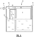
- spiral pump 20 comprises a housing 22 which is divided into two chambers: an exit chamber 24 and an entry chamber 26. Chambers 24, 26 of housing 22 are separated by partition wall 28.
- water 30 which is introduced via an inlet (not shown) into entry chamber 26 of housing 22.
- Pump body 2 is situated in entry chamber 26 so that entrance openings 8a, 8b, 8c can alternately take air and water into entry chamber 26.
- Outlet 10 of pump body 2 protrudes however through wall 28 and thereby debouches into exit chamber 24.
- the water leaves exit chamber 24 via an exit (not shown) of this chamber 24.
- a seal is further provided on outlet 10 in exit chamber 24 between outlet 10 and partition wall 28.
- Housing 22 is embodied as a pressure chamber.
- a conduit 32 Provided in exit chamber 24 is a conduit 32, a first outer end of which is located at the height of the rotation axis of pump body 2.
- the other outer end of conduit 32 is located some distance above the first outer end and protrudes through wall 28 into entry chamber 26.
- Entry chamber 26 comprises a conduit 34, a first outer end of which is located at the height of the rotation axis of pump body 2, while the other outer end of conduit 34 debouches outside housing 22.
- a pump 36 is moreover provided which is configured to pump air or another gas into exit chamber 24 of housing 22.
- pump body 2 In use pump body 2 is rotated by means of a drive which engages on shaft 12. Entrance openings 8a, 8b, 8c alternately take in air and water.
- Pump 36 pumps air continuously into exit chamber 24, whereby an overpressure is created in exit chamber 24.
- the air can leave exit chamber 24 via the first outer end of conduit 32 positioned at the height of the rotation axis of pump body 2.
- the water level in exit chamber 24 will hereby remain at the height of the rotation axis.
- the air introduced via conduit 32 into entry chamber 26 will there likewise create an overpressure, wherein it is generally the case that P exit chamber > P entry chamber .
- the air can escape from entry chamber 26 via a lower outer end of conduit 34 which is likewise positioned at the height of the rotation axis of pump body 2.
- the water level 30 in entry chamber 26 is thus also held at the height of the rotation axis of pump body 2. It is generally the case that P exit chamber > P entry chamber > P atmospheric . In short, the water level is set at the height of the rotation axis of pump body 2 by the supply of air by means of pump 36 and conduits 24 and 26. Pump body 2 is thus always roughly half under water.
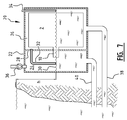
- Spiral pump 2 is for instance used for biological treatment of pond water ( figure 7 ).
- the water level in housing 22 is lower than the water level in the pond.
- the difference h in water level is possible because of the pressure built up in the housing 22 embodied as pressure chamber.
- the pond water to be treated is carried via an feed conduit 38 into housing 22.
- Feed conduit 38 debouches into a lower part of entry chamber 26, i.e. at a height below water level 30.
- Treated water can be fed back to the pond via discharge conduit 40.
- Discharge conduit 40 is provided on an underside of exit chamber 24, i.e. at a height below water level 30. It is noted that due to the pumping action of spiral pump 20 no additional pumps are necessary to feed the water into and out of the pond.
- pond water is guided directly to spiral pump 20.
- a mechanical filter will usually be present so that solids are filtered out of the water before the water is treated by means of spiral pump 20.
- Further devices can optionally be provided for the treatment of the water prior to or following biological treatment by spiral pump 20.
Landscapes
- Life Sciences & Earth Sciences (AREA)
- Engineering & Computer Science (AREA)
- Mechanical Engineering (AREA)
- General Engineering & Computer Science (AREA)
- Environmental Sciences (AREA)
- Biodiversity & Conservation Biology (AREA)
- Marine Sciences & Fisheries (AREA)
- Animal Husbandry (AREA)
- Microbiology (AREA)
- Hydrology & Water Resources (AREA)
- Environmental & Geological Engineering (AREA)
- Water Supply & Treatment (AREA)
- Chemical & Material Sciences (AREA)
- Organic Chemistry (AREA)
- Health & Medical Sciences (AREA)
- Molecular Biology (AREA)
- Geometry (AREA)
- Physics & Mathematics (AREA)
- Structures Of Non-Positive Displacement Pumps (AREA)
- Biological Treatment Of Waste Water (AREA)
- Aeration Devices For Treatment Of Activated Polluted Sludge (AREA)
Applications Claiming Priority (1)
| Application Number | Priority Date | Filing Date | Title |
|---|---|---|---|
| NL2015254A NL2015254B1 (nl) | 2015-08-03 | 2015-08-03 | Spiraalpomp, inrichting voor het behandelen van water en bijbehorende werkwijze |
Publications (2)
| Publication Number | Publication Date |
|---|---|
| EP3127873A1 true EP3127873A1 (de) | 2017-02-08 |
| EP3127873B1 EP3127873B1 (de) | 2019-01-30 |
Family
ID=55273455
Family Applications (1)
| Application Number | Title | Priority Date | Filing Date |
|---|---|---|---|
| EP16182330.7A Not-in-force EP3127873B1 (de) | 2015-08-03 | 2016-08-02 | Spiralpumpe, vorrichtung und verfahren zur bereitstellung der spiralpumpe |
Country Status (3)
| Country | Link |
|---|---|
| US (1) | US20170037862A1 (de) |
| EP (1) | EP3127873B1 (de) |
| NL (1) | NL2015254B1 (de) |
Cited By (1)
| Publication number | Priority date | Publication date | Assignee | Title |
|---|---|---|---|---|
| CN118216471A (zh) * | 2024-03-26 | 2024-06-21 | 江苏海陵湖生态科技发展有限公司 | 一种具有自动增氧功能的大宗淡水鱼养殖用水质监测装置 |
Citations (4)
| Publication number | Priority date | Publication date | Assignee | Title |
|---|---|---|---|---|
| US4010102A (en) * | 1974-02-14 | 1977-03-01 | Parca Norrahammar Ab | Liquid treatment apparatus having parallel rotating baffles |
| DE2919221A1 (de) * | 1979-05-12 | 1980-11-20 | Glahn Hanns Ing Grad | Rotierender hohlspiraltropfkoerper zur chemophysikalisch - biologischen abwasserreinigung |
| GB2119783A (en) | 1982-05-13 | 1983-11-23 | Nat Res Dev | Improvements in or relating to liquid purifying |
| GB2134400A (en) * | 1983-01-21 | 1984-08-15 | Geoffrey Howard Mortimer | Improvements in or relating to liquid-dispensing apparatus |
-
2015
- 2015-08-03 NL NL2015254A patent/NL2015254B1/nl not_active IP Right Cessation
-
2016
- 2016-08-02 EP EP16182330.7A patent/EP3127873B1/de not_active Not-in-force
- 2016-08-02 US US15/226,381 patent/US20170037862A1/en not_active Abandoned
Patent Citations (4)
| Publication number | Priority date | Publication date | Assignee | Title |
|---|---|---|---|---|
| US4010102A (en) * | 1974-02-14 | 1977-03-01 | Parca Norrahammar Ab | Liquid treatment apparatus having parallel rotating baffles |
| DE2919221A1 (de) * | 1979-05-12 | 1980-11-20 | Glahn Hanns Ing Grad | Rotierender hohlspiraltropfkoerper zur chemophysikalisch - biologischen abwasserreinigung |
| GB2119783A (en) | 1982-05-13 | 1983-11-23 | Nat Res Dev | Improvements in or relating to liquid purifying |
| GB2134400A (en) * | 1983-01-21 | 1984-08-15 | Geoffrey Howard Mortimer | Improvements in or relating to liquid-dispensing apparatus |
Cited By (1)
| Publication number | Priority date | Publication date | Assignee | Title |
|---|---|---|---|---|
| CN118216471A (zh) * | 2024-03-26 | 2024-06-21 | 江苏海陵湖生态科技发展有限公司 | 一种具有自动增氧功能的大宗淡水鱼养殖用水质监测装置 |
Also Published As
| Publication number | Publication date |
|---|---|
| EP3127873B1 (de) | 2019-01-30 |
| US20170037862A1 (en) | 2017-02-09 |
| NL2015254B1 (nl) | 2017-02-20 |
Similar Documents
| Publication | Publication Date | Title |
|---|---|---|
| US9392775B2 (en) | Fish culturing system | |
| US8506811B2 (en) | Process and system for growing crustaceans and other fish | |
| US5221470A (en) | Apparatus for treating waste water | |
| CN102329025B (zh) | 一种原水处理系统 | |
| US5779885A (en) | Rotating biological filter system | |
| KR101034651B1 (ko) | 호소용 물순환장치 | |
| EP3127873B1 (de) | Spiralpumpe, vorrichtung und verfahren zur bereitstellung der spiralpumpe | |
| US8133394B2 (en) | Method for purifying wastewater | |
| EP2121159B1 (de) | Kieskammer und steuerverfahren dafür | |
| JPH11197420A (ja) | 濾過装置 | |
| US9920291B1 (en) | Biochemical reactor with tank inlet disposed above lower divider | |
| KR101844423B1 (ko) | 저장수 정화장치 | |
| JPH11197681A (ja) | 濾過装置 | |
| RU2698694C1 (ru) | Способ аэробной биологической очистки сточных вод взвешенным активным илом с гидроавтоматическим режимом регулирования скорости рециркуляции в зависимости от единовременных объемов неравномерно подаваемых сточных вод частных домов и специальным ночным режимом денитрификации и устройство для его осуществления | |
| WO2018164720A1 (en) | Home sewage treatment system | |
| CN209442821U (zh) | 污水处理设备 | |
| CN215559721U (zh) | 地埋式微生物降解污水处理装置 | |
| FI20175367A1 (fi) | Bioreaktori | |
| CN219088167U (zh) | 景观鱼池处理设备 | |
| CN206901840U (zh) | 一种环境保护污水处理装置 | |
| KR101879668B1 (ko) | 해수 양식장 배출수 복합산화 처리장치 및 이를 이용한 해수 양식장 배출수 복합산화 처리방법 | |
| RU2769426C1 (ru) | Гидроциклонный аэротенк с аэробной стабилизацией избыточного активного ила | |
| RU2799647C1 (ru) | Аэратор подземных вод с погружным насосом | |
| JPH0889133A (ja) | 水槽の濾過装置 | |
| EP2209747B1 (de) | Anlage zur abwasserbehandlung |
Legal Events
| Date | Code | Title | Description |
|---|---|---|---|
| PUAI | Public reference made under article 153(3) epc to a published international application that has entered the european phase |
Free format text: ORIGINAL CODE: 0009012 |
|
| STAA | Information on the status of an ep patent application or granted ep patent |
Free format text: STATUS: THE APPLICATION HAS BEEN PUBLISHED |
|
| AK | Designated contracting states |
Kind code of ref document: A1 Designated state(s): AL AT BE BG CH CY CZ DE DK EE ES FI FR GB GR HR HU IE IS IT LI LT LU LV MC MK MT NL NO PL PT RO RS SE SI SK SM TR |
|
| AX | Request for extension of the european patent |
Extension state: BA ME |
|
| STAA | Information on the status of an ep patent application or granted ep patent |
Free format text: STATUS: REQUEST FOR EXAMINATION WAS MADE |
|
| 17P | Request for examination filed |
Effective date: 20170801 |
|
| RBV | Designated contracting states (corrected) |
Designated state(s): AL AT BE BG CH CY CZ DE DK EE ES FI FR GB GR HR HU IE IS IT LI LT LU LV MC MK MT NL NO PL PT RO RS SE SI SK SM TR |
|
| GRAP | Despatch of communication of intention to grant a patent |
Free format text: ORIGINAL CODE: EPIDOSNIGR1 |
|
| STAA | Information on the status of an ep patent application or granted ep patent |
Free format text: STATUS: GRANT OF PATENT IS INTENDED |
|
| INTG | Intention to grant announced |
Effective date: 20180927 |
|
| GRAS | Grant fee paid |
Free format text: ORIGINAL CODE: EPIDOSNIGR3 |
|
| GRAA | (expected) grant |
Free format text: ORIGINAL CODE: 0009210 |
|
| STAA | Information on the status of an ep patent application or granted ep patent |
Free format text: STATUS: THE PATENT HAS BEEN GRANTED |
|
| AK | Designated contracting states |
Kind code of ref document: B1 Designated state(s): AL AT BE BG CH CY CZ DE DK EE ES FI FR GB GR HR HU IE IS IT LI LT LU LV MC MK MT NL NO PL PT RO RS SE SI SK SM TR |
|
| REG | Reference to a national code |
Ref country code: GB Ref legal event code: FG4D |
|
| REG | Reference to a national code |
Ref country code: CH Ref legal event code: EP |
|
| REG | Reference to a national code |
Ref country code: AT Ref legal event code: REF Ref document number: 1093107 Country of ref document: AT Kind code of ref document: T Effective date: 20190215 |
|
| REG | Reference to a national code |
Ref country code: IE Ref legal event code: FG4D |
|
| REG | Reference to a national code |
Ref country code: DE Ref legal event code: R096 Ref document number: 602016009590 Country of ref document: DE |
|
| REG | Reference to a national code |
Ref country code: NL Ref legal event code: FP |
|
| REG | Reference to a national code |
Ref country code: LT Ref legal event code: MG4D |
|
| PG25 | Lapsed in a contracting state [announced via postgrant information from national office to epo] |
Ref country code: PL Free format text: LAPSE BECAUSE OF FAILURE TO SUBMIT A TRANSLATION OF THE DESCRIPTION OR TO PAY THE FEE WITHIN THE PRESCRIBED TIME-LIMIT Effective date: 20190130 Ref country code: LT Free format text: LAPSE BECAUSE OF FAILURE TO SUBMIT A TRANSLATION OF THE DESCRIPTION OR TO PAY THE FEE WITHIN THE PRESCRIBED TIME-LIMIT Effective date: 20190130 Ref country code: SE Free format text: LAPSE BECAUSE OF FAILURE TO SUBMIT A TRANSLATION OF THE DESCRIPTION OR TO PAY THE FEE WITHIN THE PRESCRIBED TIME-LIMIT Effective date: 20190130 Ref country code: NO Free format text: LAPSE BECAUSE OF FAILURE TO SUBMIT A TRANSLATION OF THE DESCRIPTION OR TO PAY THE FEE WITHIN THE PRESCRIBED TIME-LIMIT Effective date: 20190430 Ref country code: ES Free format text: LAPSE BECAUSE OF FAILURE TO SUBMIT A TRANSLATION OF THE DESCRIPTION OR TO PAY THE FEE WITHIN THE PRESCRIBED TIME-LIMIT Effective date: 20190130 Ref country code: PT Free format text: LAPSE BECAUSE OF FAILURE TO SUBMIT A TRANSLATION OF THE DESCRIPTION OR TO PAY THE FEE WITHIN THE PRESCRIBED TIME-LIMIT Effective date: 20190530 Ref country code: FI Free format text: LAPSE BECAUSE OF FAILURE TO SUBMIT A TRANSLATION OF THE DESCRIPTION OR TO PAY THE FEE WITHIN THE PRESCRIBED TIME-LIMIT Effective date: 20190130 |
|
| REG | Reference to a national code |
Ref country code: AT Ref legal event code: MK05 Ref document number: 1093107 Country of ref document: AT Kind code of ref document: T Effective date: 20190130 |
|
| PG25 | Lapsed in a contracting state [announced via postgrant information from national office to epo] |
Ref country code: BG Free format text: LAPSE BECAUSE OF FAILURE TO SUBMIT A TRANSLATION OF THE DESCRIPTION OR TO PAY THE FEE WITHIN THE PRESCRIBED TIME-LIMIT Effective date: 20190430 Ref country code: RS Free format text: LAPSE BECAUSE OF FAILURE TO SUBMIT A TRANSLATION OF THE DESCRIPTION OR TO PAY THE FEE WITHIN THE PRESCRIBED TIME-LIMIT Effective date: 20190130 Ref country code: LV Free format text: LAPSE BECAUSE OF FAILURE TO SUBMIT A TRANSLATION OF THE DESCRIPTION OR TO PAY THE FEE WITHIN THE PRESCRIBED TIME-LIMIT Effective date: 20190130 Ref country code: IS Free format text: LAPSE BECAUSE OF FAILURE TO SUBMIT A TRANSLATION OF THE DESCRIPTION OR TO PAY THE FEE WITHIN THE PRESCRIBED TIME-LIMIT Effective date: 20190530 Ref country code: HR Free format text: LAPSE BECAUSE OF FAILURE TO SUBMIT A TRANSLATION OF THE DESCRIPTION OR TO PAY THE FEE WITHIN THE PRESCRIBED TIME-LIMIT Effective date: 20190130 Ref country code: GR Free format text: LAPSE BECAUSE OF FAILURE TO SUBMIT A TRANSLATION OF THE DESCRIPTION OR TO PAY THE FEE WITHIN THE PRESCRIBED TIME-LIMIT Effective date: 20190501 |
|
| PG25 | Lapsed in a contracting state [announced via postgrant information from national office to epo] |
Ref country code: DK Free format text: LAPSE BECAUSE OF FAILURE TO SUBMIT A TRANSLATION OF THE DESCRIPTION OR TO PAY THE FEE WITHIN THE PRESCRIBED TIME-LIMIT Effective date: 20190130 Ref country code: SK Free format text: LAPSE BECAUSE OF FAILURE TO SUBMIT A TRANSLATION OF THE DESCRIPTION OR TO PAY THE FEE WITHIN THE PRESCRIBED TIME-LIMIT Effective date: 20190130 Ref country code: AL Free format text: LAPSE BECAUSE OF FAILURE TO SUBMIT A TRANSLATION OF THE DESCRIPTION OR TO PAY THE FEE WITHIN THE PRESCRIBED TIME-LIMIT Effective date: 20190130 Ref country code: EE Free format text: LAPSE BECAUSE OF FAILURE TO SUBMIT A TRANSLATION OF THE DESCRIPTION OR TO PAY THE FEE WITHIN THE PRESCRIBED TIME-LIMIT Effective date: 20190130 Ref country code: IT Free format text: LAPSE BECAUSE OF FAILURE TO SUBMIT A TRANSLATION OF THE DESCRIPTION OR TO PAY THE FEE WITHIN THE PRESCRIBED TIME-LIMIT Effective date: 20190130 Ref country code: CZ Free format text: LAPSE BECAUSE OF FAILURE TO SUBMIT A TRANSLATION OF THE DESCRIPTION OR TO PAY THE FEE WITHIN THE PRESCRIBED TIME-LIMIT Effective date: 20190130 Ref country code: RO Free format text: LAPSE BECAUSE OF FAILURE TO SUBMIT A TRANSLATION OF THE DESCRIPTION OR TO PAY THE FEE WITHIN THE PRESCRIBED TIME-LIMIT Effective date: 20190130 |
|
| REG | Reference to a national code |
Ref country code: DE Ref legal event code: R097 Ref document number: 602016009590 Country of ref document: DE |
|
| PG25 | Lapsed in a contracting state [announced via postgrant information from national office to epo] |
Ref country code: SM Free format text: LAPSE BECAUSE OF FAILURE TO SUBMIT A TRANSLATION OF THE DESCRIPTION OR TO PAY THE FEE WITHIN THE PRESCRIBED TIME-LIMIT Effective date: 20190130 |
|
| PLBE | No opposition filed within time limit |
Free format text: ORIGINAL CODE: 0009261 |
|
| STAA | Information on the status of an ep patent application or granted ep patent |
Free format text: STATUS: NO OPPOSITION FILED WITHIN TIME LIMIT |
|
| PG25 | Lapsed in a contracting state [announced via postgrant information from national office to epo] |
Ref country code: AT Free format text: LAPSE BECAUSE OF FAILURE TO SUBMIT A TRANSLATION OF THE DESCRIPTION OR TO PAY THE FEE WITHIN THE PRESCRIBED TIME-LIMIT Effective date: 20190130 |
|
| 26N | No opposition filed |
Effective date: 20191031 |
|
| PG25 | Lapsed in a contracting state [announced via postgrant information from national office to epo] |
Ref country code: SI Free format text: LAPSE BECAUSE OF FAILURE TO SUBMIT A TRANSLATION OF THE DESCRIPTION OR TO PAY THE FEE WITHIN THE PRESCRIBED TIME-LIMIT Effective date: 20190130 |
|
| REG | Reference to a national code |
Ref country code: DE Ref legal event code: R119 Ref document number: 602016009590 Country of ref document: DE |
|
| PG25 | Lapsed in a contracting state [announced via postgrant information from national office to epo] |
Ref country code: TR Free format text: LAPSE BECAUSE OF FAILURE TO SUBMIT A TRANSLATION OF THE DESCRIPTION OR TO PAY THE FEE WITHIN THE PRESCRIBED TIME-LIMIT Effective date: 20190130 |
|
| REG | Reference to a national code |
Ref country code: NL Ref legal event code: MM Effective date: 20190901 |
|
| PG25 | Lapsed in a contracting state [announced via postgrant information from national office to epo] |
Ref country code: LI Free format text: LAPSE BECAUSE OF NON-PAYMENT OF DUE FEES Effective date: 20190831 Ref country code: MC Free format text: LAPSE BECAUSE OF FAILURE TO SUBMIT A TRANSLATION OF THE DESCRIPTION OR TO PAY THE FEE WITHIN THE PRESCRIBED TIME-LIMIT Effective date: 20190130 Ref country code: CH Free format text: LAPSE BECAUSE OF NON-PAYMENT OF DUE FEES Effective date: 20190831 Ref country code: LU Free format text: LAPSE BECAUSE OF NON-PAYMENT OF DUE FEES Effective date: 20190802 |
|
| REG | Reference to a national code |
Ref country code: BE Ref legal event code: MM Effective date: 20190831 |
|
| PG25 | Lapsed in a contracting state [announced via postgrant information from national office to epo] |
Ref country code: IE Free format text: LAPSE BECAUSE OF NON-PAYMENT OF DUE FEES Effective date: 20190802 Ref country code: FR Free format text: LAPSE BECAUSE OF NON-PAYMENT OF DUE FEES Effective date: 20190831 Ref country code: NL Free format text: LAPSE BECAUSE OF NON-PAYMENT OF DUE FEES Effective date: 20190901 Ref country code: DE Free format text: LAPSE BECAUSE OF NON-PAYMENT OF DUE FEES Effective date: 20200303 |
|
| PG25 | Lapsed in a contracting state [announced via postgrant information from national office to epo] |
Ref country code: BE Free format text: LAPSE BECAUSE OF NON-PAYMENT OF DUE FEES Effective date: 20190831 |
|
| GBPC | Gb: european patent ceased through non-payment of renewal fee |
Effective date: 20200802 |
|
| PG25 | Lapsed in a contracting state [announced via postgrant information from national office to epo] |
Ref country code: CY Free format text: LAPSE BECAUSE OF FAILURE TO SUBMIT A TRANSLATION OF THE DESCRIPTION OR TO PAY THE FEE WITHIN THE PRESCRIBED TIME-LIMIT Effective date: 20190130 |
|
| PG25 | Lapsed in a contracting state [announced via postgrant information from national office to epo] |
Ref country code: HU Free format text: LAPSE BECAUSE OF FAILURE TO SUBMIT A TRANSLATION OF THE DESCRIPTION OR TO PAY THE FEE WITHIN THE PRESCRIBED TIME-LIMIT; INVALID AB INITIO Effective date: 20160802 Ref country code: MT Free format text: LAPSE BECAUSE OF FAILURE TO SUBMIT A TRANSLATION OF THE DESCRIPTION OR TO PAY THE FEE WITHIN THE PRESCRIBED TIME-LIMIT Effective date: 20190130 |
|
| PG25 | Lapsed in a contracting state [announced via postgrant information from national office to epo] |
Ref country code: GB Free format text: LAPSE BECAUSE OF NON-PAYMENT OF DUE FEES Effective date: 20200802 |
|
| PG25 | Lapsed in a contracting state [announced via postgrant information from national office to epo] |
Ref country code: MK Free format text: LAPSE BECAUSE OF FAILURE TO SUBMIT A TRANSLATION OF THE DESCRIPTION OR TO PAY THE FEE WITHIN THE PRESCRIBED TIME-LIMIT Effective date: 20190130 |