EP3128053A1 - Dispositif d'entrainement d'une machine de peignage - Google Patents
Dispositif d'entrainement d'une machine de peignage Download PDFInfo
- Publication number
- EP3128053A1 EP3128053A1 EP16180090.9A EP16180090A EP3128053A1 EP 3128053 A1 EP3128053 A1 EP 3128053A1 EP 16180090 A EP16180090 A EP 16180090A EP 3128053 A1 EP3128053 A1 EP 3128053A1
- Authority
- EP
- European Patent Office
- Prior art keywords
- belt
- pulley
- drive device
- motor
- drive
- Prior art date
- Legal status (The legal status is an assumption and is not a legal conclusion. Google has not performed a legal analysis and makes no representation as to the accuracy of the status listed.)
- Withdrawn
Links
Images
Classifications
-
- D—TEXTILES; PAPER
- D01—NATURAL OR MAN-MADE THREADS OR FIBRES; SPINNING
- D01G—PRELIMINARY TREATMENT OF FIBRES, e.g. FOR SPINNING
- D01G19/00—Combing machines
- D01G19/06—Details
- D01G19/26—Driving arrangements
-
- F—MECHANICAL ENGINEERING; LIGHTING; HEATING; WEAPONS; BLASTING
- F16—ENGINEERING ELEMENTS AND UNITS; GENERAL MEASURES FOR PRODUCING AND MAINTAINING EFFECTIVE FUNCTIONING OF MACHINES OR INSTALLATIONS; THERMAL INSULATION IN GENERAL
- F16G—BELTS, CABLES, OR ROPES, PREDOMINANTLY USED FOR DRIVING PURPOSES; CHAINS; FITTINGS PREDOMINANTLY USED THEREFOR
- F16G5/00—V-belts, i.e. belts of tapered cross-section
- F16G5/20—V-belts, i.e. belts of tapered cross-section with a contact surface of special shape, e.g. toothed
Definitions
- the invention relates to a drive device between a motor having an output shaft and a gear unit of a combing machine having an input shaft from which working elements of the comber are driven, wherein a motor pulley is arranged on the output shaft of the motor and a gear pulley on the input shaft of the gear unit and wherein a drive means frictionally cooperates with the engine pulley and transmission pulley.
- the mechanical drive system includes a gear unit having an input shaft, the input shaft receiving power from an engine via a V-belt pulley. In this way, up to 350 combing games per minute (KS / min) could be carried out with the combing machine of the time, whereby a single V-belt was used as drive means.
- the very strong vibration behavior of the double V-belt in particular means that the engine has to apply a higher power to drive the gear unit of the comber, whereby very high strain changes act on the double V-belt, which in turn significantly reduces their life.
- the double V-belt acts as a clamped string due to the very strong vibration behavior of the drive system, which vibrates in its natural frequency, resulting in an undesirable noise level.
- the invention is therefore based on the object to provide a drive device between a motor and a gear unit of a comber, which allows an improved drive transmission and minimizes the wear of the drive means and the undesirable noise level.
- the drive means is designed as a V-ribbed belt, in particular poly-V-belt.
- the V-ribbed belt allows a lower wrap angle with the engine pulley as well as the transmission pulley as compared to the V-belt. This has the consequence that the uneven vibrations of the Gear pulley with a lower power transmission to the Switzerlandtrum act and thus the mechanical stress on the bearings of the transmission and the engine are significantly cushioned. Furthermore, there is less fluttering of the belt and, because of the large wrap around, less slip, which results in better transmission of engine power.
- the working power of the engine could be lowered by 150 W to 200 W. It has also been found to be beneficial that the torque peak on the output shaft of the motor has improved by between about 15% to about 20%. Also, an increased efficiency could be achieved with the V-ribbed belt.
- the V-ribbed belt has its advantages especially with combing machines with combing speeds of up to 650 KS / min.
- a V-ribbed belt should have a PJ profile with between 5 and 10 ribs, preferably between 7 and 9 ribs, and more preferably 8 ribs, in order to counteract the uneven vibrations of the gear unit.
- the V-ribbed belt in particular Poly-V belt, with the PJ profile conforms to the standard DIN 7867 / ISO 9982 and has a base, a tension cord and a cover plate.
- the substructure has wedge-shaped, parallel arranged in the direction of ribs. These ribs ensure a good adhesion and a uniform force distribution over the entire belt width.
- the substructure consists of an elastomeric material.
- the tension cord consists of a polyester cord or aramid cord of high strength and low elongation and is firmly connected to the substructure.
- the wear-resistant pressure plate ensures lasting protection of the tension cord.
- the PJ profile has a rib distance of about 2.34 mm and a belt height of about 3.8 mm.
- the motor pulley and the gear pulley have on their respective outer periphery a diametrically opposed ribbed profile for the V-ribbed belt on. This allows optimum power transmission between the V-ribbed belt and the pulleys.
- the V-ribbed belt pulley should also be manufactured according to DIN 7867 / ISO 9982.
- At least one flywheel on the input shaft of the gear unit is arranged radially outwardly from the gear pulley. This has the advantageous effect that the flywheel absorbs the load peaks in the drive system.
- the mass inertia of the at least one flywheel is between about 84000 kg * mm2 and about 85000 kg * mm2, preferably between about 84300 kg * mm2 and about 84800 kg * mm2, and more preferably 84600 kg * mm2 should lie.
- the weight of the at least one flywheel should be between about 7.0 kg and about 7.5 kg, preferably between about 7.2 kg and about 7.4 kg, and more preferably about 7.3 kg.
- a weight of the flywheel on the input shaft of the gear unit should be accompanied by a slow start and brake of the engine and also causes extensive loads on the input shaft, these effects are rather lower than the dominant advantage that the vibration behavior of the drive system in Switzerlandtrum can be significantly minimized.
- the flywheel in one piece or in several parts.
- the use of at least one deflection roller is advantageously provided, wherein the deflection roller cooperates with the traction element of the drive means. This has the advantageous effect of dividing the draft strand. Accordingly, the deflection roller counteracts the increased slip in Switzerlandtrum.
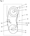
- Fig. 1 shows purely schematically a drive device 10 between an output shaft 12 having a motor 14 and an input shaft 16 having a gear unit 18 of a combing machine 20 according to the known prior art.
- the gear unit 18 and the comber 20 these components are in Fig. 1 shown in dashed lines.
- the gear unit 18 working elements (not shown) of the combing machine 20 are driven.
- a transmission pulley 24 On the output shaft 12 of the engine 14 is a motor pulley 22 and on the input shaft 16 of the transmission unit 18, a transmission pulley 24 is arranged.
- a drive means 26 cooperates frictionally with the motor pulley 22 and gear pulley 24.
- the gear unit 18 of the known combing machine 20 drives the ripper for the vocational step, the pliers of the nipper unit for the reciprocating motion and the circular comb for a non-uniform movement. These drives cause Especially in today's combing machines with up to 600 KS / min an uneven vibration on the drive system and thus lead to undesirable load peaks on the working elements of the comber 20, the output shaft 12 of the motor 14 and the input shaft 16 of the transmission unit 18th
- Fig. 1 In the known state of the art for drive devices of a comber according to Fig. 1 serves a double V-belt 26A as a drive means 20.
- This double V-belt 26A begins at up to 600 KS / min because of the uneven vibrations from the transmission unit 18 to swing or flutter. This so-called fluttering of the double V-belt 26A is in Fig. 1 indicated by dotted lines in Switzerlandtrum 28.
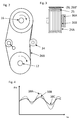
- FIG. 2 is, starting from the known state of the art as in Fig. 1 shown, the double V-belt 26A replaced by a V-ribbed belt 26B, in particular PolyV-belt 26B '.
- a clearer illustration of the V-ribbed belt 26B as the drive means 26 is shown in FIG Fig. 3 shown in detail.
- V-ribbed belt 26B has a considerably better vibration behavior (see Fig. 2 dotted line in Switzerlandtrum 28) in comparison to the double V-belt 26A according to Fig. 1 ,
- FIG Fig. 3 Another possibility for minimizing the fluttering behavior of the V-ribbed belt 26B is shown in FIG Fig. 3 indicated by two dashed pulleys 36A, 36B.
- the two flywheels 36A, 36B are arranged on the input shaft 14 radially outward to the corresponding gear pulley 24A and thus mechanically cushion the uneven oscillation of the gear unit 18.
- Fig. 3 it can be seen how the poly-V belt 26B 'of the type PJ-8 cooperates with a counterpart 8-groove profile 25 on the corresponding gear pulley 24A.
- the V-ribbed belt 26B in particular poly-V belt 26B 'of the type PJ-8 corresponds to the standard DIN 7867 / ISO 9982 and has a base, a pull cord and a cover plate.
- the substructure has wedge-shaped, parallel arranged in the direction of ribs. These ribs ensure a good adhesion and a uniform force distribution over the entire belt width.
- the substructure consists of an elastomeric material.
- the tension cord consists of a polyester cord or aramid cord of high strength and low elongation and is firmly connected to the substructure.
- the wear-resistant pressure plate ensures lasting protection of the tension cord.
- the first cornering 38A is shown in dotted lines and indicates the torque behavior of the motor 14 with the double V-belt 26A Fig. 1 again.
- the torque peaks on the motor 14 are very high in arithmetic mean with the double V-belt 26A and thus reflect the very strong vibration behavior of the drive system.
- the second curve 38B is shown in phantom and represents the torque behavior of the motor 14 with the poly-V belt 26B 'of the tire PJ-8.
- the second curve 38B with the poly-V belt 26B 'of the type PJ-8 shows a significantly improved curve and thus greatly reduced torque peaks on the engine 14. It could be in the arithmetic mean a cushioning of Vibration behavior on the drive system of up to 11% to 20% can be achieved.
- the third curve 38C is shown in solid lines and indicates the torque behavior of the motor 14 with the poly-V belt 26B 'of the type PJ-8 with the two flywheels 36A, 36B according to Fig. 3 again.
- the use of the two flywheels 36A, 36B leads to a further mechanical cushioning of the vibration behavior on the drive system, however, the replacement of the double V-belt 26A to the poly-V belt 26B 'of the type PJ-8 has provided a much greater improvement.
Landscapes
- Engineering & Computer Science (AREA)
- Textile Engineering (AREA)
- Devices For Conveying Motion By Means Of Endless Flexible Members (AREA)
- Preliminary Treatment Of Fibers (AREA)
Applications Claiming Priority (1)
| Application Number | Priority Date | Filing Date | Title |
|---|---|---|---|
| CH01132/15A CH711419A2 (de) | 2015-08-05 | 2015-08-05 | Antriebsvorrichtung für eine Kämmmaschine. |
Publications (1)
| Publication Number | Publication Date |
|---|---|
| EP3128053A1 true EP3128053A1 (fr) | 2017-02-08 |
Family
ID=56511354
Family Applications (1)
| Application Number | Title | Priority Date | Filing Date |
|---|---|---|---|
| EP16180090.9A Withdrawn EP3128053A1 (fr) | 2015-08-05 | 2016-07-19 | Dispositif d'entrainement d'une machine de peignage |
Country Status (3)
| Country | Link |
|---|---|
| EP (1) | EP3128053A1 (fr) |
| CN (1) | CN106435854A (fr) |
| CH (1) | CH711419A2 (fr) |
Cited By (1)
| Publication number | Priority date | Publication date | Assignee | Title |
|---|---|---|---|---|
| CH714582A1 (de) * | 2018-01-23 | 2019-07-31 | Rieter Ag Maschf | Antriebsvorrichtung für Abreisswalzen einer Kämmmaschine. |
Families Citing this family (1)
| Publication number | Priority date | Publication date | Assignee | Title |
|---|---|---|---|---|
| US11230459B2 (en) * | 2020-06-26 | 2022-01-25 | Otis Elevator Company | Belt-driven escalator |
Citations (7)
| Publication number | Priority date | Publication date | Assignee | Title |
|---|---|---|---|---|
| GB558978A (en) * | 1942-04-18 | 1944-01-28 | Platt Brothers & Co Ltd | Improvements in and relating to guards for combing machines for combing textile fibres |
| CH499635A (de) | 1967-09-30 | 1970-11-30 | Rieter Ag Maschf | Abreisswalzen-Antriebsvorrichtung an einer Kämmaschine |
| DE19801253A1 (de) * | 1998-01-15 | 1999-07-29 | Contitech Antriebssysteme Gmbh | Keilrippenriemen und Verfahren zu dessen Herstellung |
| DE69624157T2 (de) * | 1995-02-28 | 2003-06-12 | Vouk S.P.A. Officine Meccanotessili, Gorizia | Elektronisch gesteuerte Kämmaschine |
| EP1496143A2 (fr) * | 2003-07-08 | 2005-01-12 | Rieter Ingolstadt Spinnereimaschinenbau AG | Machine textile, particulièrement une machine préparatoire pour la filature, comprenant un banc d'étirage |
| CN101250777A (zh) * | 2008-03-27 | 2008-08-27 | 苏善珍 | 精梳机的圈条器传动机构 |
| CN201326051Y (zh) * | 2008-12-09 | 2009-10-14 | 晋中开发区贝斯特机械制造有限公司 | 一种精梳机的主传动装置 |
-
2015
- 2015-08-05 CH CH01132/15A patent/CH711419A2/de not_active Application Discontinuation
-
2016
- 2016-07-19 EP EP16180090.9A patent/EP3128053A1/fr not_active Withdrawn
- 2016-08-04 CN CN201610630862.1A patent/CN106435854A/zh active Pending
Patent Citations (7)
| Publication number | Priority date | Publication date | Assignee | Title |
|---|---|---|---|---|
| GB558978A (en) * | 1942-04-18 | 1944-01-28 | Platt Brothers & Co Ltd | Improvements in and relating to guards for combing machines for combing textile fibres |
| CH499635A (de) | 1967-09-30 | 1970-11-30 | Rieter Ag Maschf | Abreisswalzen-Antriebsvorrichtung an einer Kämmaschine |
| DE69624157T2 (de) * | 1995-02-28 | 2003-06-12 | Vouk S.P.A. Officine Meccanotessili, Gorizia | Elektronisch gesteuerte Kämmaschine |
| DE19801253A1 (de) * | 1998-01-15 | 1999-07-29 | Contitech Antriebssysteme Gmbh | Keilrippenriemen und Verfahren zu dessen Herstellung |
| EP1496143A2 (fr) * | 2003-07-08 | 2005-01-12 | Rieter Ingolstadt Spinnereimaschinenbau AG | Machine textile, particulièrement une machine préparatoire pour la filature, comprenant un banc d'étirage |
| CN101250777A (zh) * | 2008-03-27 | 2008-08-27 | 苏善珍 | 精梳机的圈条器传动机构 |
| CN201326051Y (zh) * | 2008-12-09 | 2009-10-14 | 晋中开发区贝斯特机械制造有限公司 | 一种精梳机的主传动装置 |
Cited By (1)
| Publication number | Priority date | Publication date | Assignee | Title |
|---|---|---|---|---|
| CH714582A1 (de) * | 2018-01-23 | 2019-07-31 | Rieter Ag Maschf | Antriebsvorrichtung für Abreisswalzen einer Kämmmaschine. |
Also Published As
| Publication number | Publication date |
|---|---|
| CH711419A2 (de) | 2017-02-15 |
| CN106435854A (zh) | 2017-02-22 |
Similar Documents
| Publication | Publication Date | Title |
|---|---|---|
| DE60306064T2 (de) | Riemenscheibe für ein stufenloses Getriebe | |
| EP2583000B1 (fr) | Plaque vibrante avec stabilisateur de courroie trapézoïdale | |
| WO2022106118A1 (fr) | Réglage et surveillance automatiques d'un entraînement à courroie | |
| DE60101218T2 (de) | Keilriemensystem | |
| CH711419A2 (de) | Antriebsvorrichtung für eine Kämmmaschine. | |
| WO2009089899A1 (fr) | Plaque vibrante dotée d'une transmission par courroie à renvoi multiple | |
| EP3093526A2 (fr) | Dispositif de transmission comprenant des poulies de tension couplees | |
| DE102010010834B4 (de) | Spannvorrichtung für einen Aggregatetrieb an einer Maschine | |
| EP1496143B1 (fr) | Machine textile, particulièrement une machine préparatoire pour la filature, comprenant un banc d'étirage | |
| DE10200686A1 (de) | Antriebseinrichtung für eine Maschinenhilfseinheit | |
| EP1837425B1 (fr) | Balancement d'un appareil de serrage dans une peigneuse | |
| CH711863A1 (de) | Kämmmaschine mit in Umfangsrichtung versetzten Kämmzylindern. | |
| DE60206678T2 (de) | Trommeltypmaschine mit einer Bewegungsübertragungsvorrichtung | |
| DE3832781A1 (de) | Keilriemenantrieb | |
| DE2432319A1 (de) | Rotationsstreckwerk | |
| EP2935668B1 (fr) | Dispositif pour acheminer et comprimer une bande d'ouate | |
| DE2108335A1 (en) | Belt drive - with drive wheels at each end to increase belting life | |
| DE10142741A1 (de) | Antrieb für eine Spinn- oder Zwirnmaschine | |
| DE10012019A1 (de) | Streckwerk für Spinnmaschine | |
| EP4219811B1 (fr) | Contrepoids pour un dispositif de peignage d'une peigneuse | |
| DE202018006198U1 (de) | Entkernmaschine zum Entkernen von Gusswerkstücken | |
| DE19708819B4 (de) | Einrichtung zur kraftschlüssigen Eingriffssicherung für Zahntriebe von umlaufenden Ausgleichsmassen bei Verbrennungsmotoren | |
| AT20787B (de) | Riemen- bezw. Seiltrieb. | |
| DE2019938A1 (de) | Spannkette fuer Spannrahmen | |
| DE92521C (fr) |
Legal Events
| Date | Code | Title | Description |
|---|---|---|---|
| PUAI | Public reference made under article 153(3) epc to a published international application that has entered the european phase |
Free format text: ORIGINAL CODE: 0009012 |
|
| AK | Designated contracting states |
Kind code of ref document: A1 Designated state(s): AL AT BE BG CH CY CZ DE DK EE ES FI FR GB GR HR HU IE IS IT LI LT LU LV MC MK MT NL NO PL PT RO RS SE SI SK SM TR |
|
| AX | Request for extension of the european patent |
Extension state: BA ME |
|
| STAA | Information on the status of an ep patent application or granted ep patent |
Free format text: STATUS: THE APPLICATION IS DEEMED TO BE WITHDRAWN |
|
| 18D | Application deemed to be withdrawn |
Effective date: 20170809 |