EP3128082B1 - Pneumatisches spritzblech und mundstück für pneumatisches spritzblech - Google Patents
Pneumatisches spritzblech und mundstück für pneumatisches spritzblech Download PDFInfo
- Publication number
- EP3128082B1 EP3128082B1 EP15773754.5A EP15773754A EP3128082B1 EP 3128082 B1 EP3128082 B1 EP 3128082B1 EP 15773754 A EP15773754 A EP 15773754A EP 3128082 B1 EP3128082 B1 EP 3128082B1
- Authority
- EP
- European Patent Office
- Prior art keywords
- fender
- open
- bladder
- hole
- receiving chamber
- Prior art date
- Legal status (The legal status is an assumption and is not a legal conclusion. Google has not performed a legal analysis and makes no representation as to the accuracy of the status listed.)
- Active
Links
Images


Classifications
-
- E—FIXED CONSTRUCTIONS
- E02—HYDRAULIC ENGINEERING; FOUNDATIONS; SOIL SHIFTING
- E02B—HYDRAULIC ENGINEERING
- E02B3/00—Engineering works in connection with control or use of streams, rivers, coasts, or other marine sites; Sealings or joints for engineering works in general
- E02B3/20—Equipment for shipping on coasts, in harbours or on other fixed marine structures, e.g. bollards
- E02B3/26—Fenders
-
- B—PERFORMING OPERATIONS; TRANSPORTING
- B63—SHIPS OR OTHER WATERBORNE VESSELS; RELATED EQUIPMENT
- B63B—SHIPS OR OTHER WATERBORNE VESSELS; EQUIPMENT FOR SHIPPING
- B63B59/00—Hull protection specially adapted for vessels; Cleaning devices specially adapted for vessels
- B63B59/02—Fenders integral with waterborne vessels or specially adapted therefor, e.g. fenders forming part of the hull or incorporated in the hull; Rubbing-strakes
-
- F—MECHANICAL ENGINEERING; LIGHTING; HEATING; WEAPONS; BLASTING
- F16—ENGINEERING ELEMENTS AND UNITS; GENERAL MEASURES FOR PRODUCING AND MAINTAINING EFFECTIVE FUNCTIONING OF MACHINES OR INSTALLATIONS; THERMAL INSULATION IN GENERAL
- F16K—VALVES; TAPS; COCKS; ACTUATING-FLOATS; DEVICES FOR VENTING OR AERATING
- F16K1/00—Lift valves or globe valves, i.e. cut-off apparatus with closure members having at least a component of their opening and closing motion perpendicular to the closing faces
-
- F—MECHANICAL ENGINEERING; LIGHTING; HEATING; WEAPONS; BLASTING
- F16—ENGINEERING ELEMENTS AND UNITS; GENERAL MEASURES FOR PRODUCING AND MAINTAINING EFFECTIVE FUNCTIONING OF MACHINES OR INSTALLATIONS; THERMAL INSULATION IN GENERAL
- F16K—VALVES; TAPS; COCKS; ACTUATING-FLOATS; DEVICES FOR VENTING OR AERATING
- F16K17/00—Safety valves; Equalising valves, e.g. pressure relief valves
- F16K17/02—Safety valves; Equalising valves, e.g. pressure relief valves opening on surplus pressure on one side; closing on insufficient pressure on one side
- F16K17/04—Safety valves; Equalising valves, e.g. pressure relief valves opening on surplus pressure on one side; closing on insufficient pressure on one side spring-loaded
- F16K17/044—Safety valves; Equalising valves, e.g. pressure relief valves opening on surplus pressure on one side; closing on insufficient pressure on one side spring-loaded with more than one spring
-
- F—MECHANICAL ENGINEERING; LIGHTING; HEATING; WEAPONS; BLASTING
- F16—ENGINEERING ELEMENTS AND UNITS; GENERAL MEASURES FOR PRODUCING AND MAINTAINING EFFECTIVE FUNCTIONING OF MACHINES OR INSTALLATIONS; THERMAL INSULATION IN GENERAL
- F16K—VALVES; TAPS; COCKS; ACTUATING-FLOATS; DEVICES FOR VENTING OR AERATING
- F16K17/00—Safety valves; Equalising valves, e.g. pressure relief valves
- F16K17/02—Safety valves; Equalising valves, e.g. pressure relief valves opening on surplus pressure on one side; closing on insufficient pressure on one side
- F16K17/04—Safety valves; Equalising valves, e.g. pressure relief valves opening on surplus pressure on one side; closing on insufficient pressure on one side spring-loaded
- F16K17/048—Safety valves; Equalising valves, e.g. pressure relief valves opening on surplus pressure on one side; closing on insufficient pressure on one side spring-loaded combined with other safety valves, or with pressure control devices
-
- B—PERFORMING OPERATIONS; TRANSPORTING
- B63—SHIPS OR OTHER WATERBORNE VESSELS; RELATED EQUIPMENT
- B63B—SHIPS OR OTHER WATERBORNE VESSELS; EQUIPMENT FOR SHIPPING
- B63B59/00—Hull protection specially adapted for vessels; Cleaning devices specially adapted for vessels
- B63B59/02—Fenders integral with waterborne vessels or specially adapted therefor, e.g. fenders forming part of the hull or incorporated in the hull; Rubbing-strakes
- B63B2059/025—Fenders integral with waterborne vessels or specially adapted therefor, e.g. fenders forming part of the hull or incorporated in the hull; Rubbing-strakes pneumatic, e.g. inflatable
-
- Y—GENERAL TAGGING OF NEW TECHNOLOGICAL DEVELOPMENTS; GENERAL TAGGING OF CROSS-SECTIONAL TECHNOLOGIES SPANNING OVER SEVERAL SECTIONS OF THE IPC; TECHNICAL SUBJECTS COVERED BY FORMER USPC CROSS-REFERENCE ART COLLECTIONS [XRACs] AND DIGESTS
- Y02—TECHNOLOGIES OR APPLICATIONS FOR MITIGATION OR ADAPTATION AGAINST CLIMATE CHANGE
- Y02A—TECHNOLOGIES FOR ADAPTATION TO CLIMATE CHANGE
- Y02A30/00—Adapting or protecting infrastructure or their operation
- Y02A30/30—Adapting or protecting infrastructure or their operation in transportation, e.g. on roads, waterways or railways
Definitions
- the present invention relates to a pneumatic fender and a mouth piece metal for a pneumatic fender, and further relates to a pneumatic fender and a mouth piece metal for a pneumatic fender with significantly enhanced maintainability wherein a safety valve can be detached and attached and a confirmation test of the valve opening pressure of the safety valve can be performed on the pneumatic fender while in use, and the labor and time required for these operations are greatly reduced.
- Pneumatic fenders are designed to have air sealed in the cavity of a fender bladder so as to be provided with predetermined performance such as shock absorbing performance. If the fender bladder remains sealed when the fender is excessively compressed, the internal pressure in the cavity may increase beyond a preset pressure threshold and cause failure of the fender bladder. To combat this, a safety valve that connects the cavity to the outside air may be provided on a mouth piece metal provided on the fender bladder for such cases when the internal pressure of the cavity of the fender bladder exceeds the pressure threshold (see, for example, Patent Document, which document discloses the features of the preamble of clam 1.
- Such a safety valve is routinely (for example, every 1 to 3 years) detached from the mouth piece metal for confirmation testing of the value opening pressure, cleaning, and other such maintenance.
- the cavity of the fender bladder of such a pneumatic fender when in use is inflated to a predetermined internal pressure, and so detaching the safety valve from the mouth piece metal of the fender bladder when the pneumatic fender is in use would result in air being violently ejected from the cavity.
- the detachment of the safety valve is not possible. Accordingly, the detachment of the safety valve is performed after sufficiently discharging the air from the cavity of the fender bladder.
- the in-use pneumatic fender is brought onto land or a marine vessel before the air is discharged.
- the safety valve Upon completion of the confirmation testing of the valve opening pressure, cleaning, and the like of the detached safety valve, the safety valve must be reattached to the mouth piece metal, the cavity of the fender bladder must be inflated with air, and the pneumatic fender must be installed in a predetermined position. Accordingly, the maintenance of detaching and attaching the safety valve to the mouth piece metal requires a great deal of man-hours and time.
- Patent Document 1 Japanese Unexamined Patent Application Publication No. 2003-129446A
- An object of the present invention is to provide a pneumatic fender and a mouth piece metal for a pneumatic fender with significantly enhanced maintainability wherein a safety valve can be attached and detached and a confirmation test of the valve opening pressure of the safety valve can be performed on the pneumatic fender while in use, and the labor and time required for these operations are greatly reduced.
- a mouth piece metal for a pneumatic fender having the features of claim 1.
- the invention provides further a pneumatic fender according to claim 4.
- the mouth piece metal includes a receiving chamber that isolates the safety valve from the cavity of the fender bladder, a through hole that connects a cavity of the receiving chamber and the cavity of the fender bladder, the through hole being formed on a dividing wall constituting the receiving chamber, an open/close valve that opens and closes the through hole, a closed position fixing member that fixes the open/close valve at a position in which the through hole is closed, an open position fixing member that fixes the open/close valve at a position in which the through hole is open.
- the closed position fixing member and the open position fixing member are disposed outside of the receiving chamber at a position to a surface side of the mouth piece metal, thus when the open/close valve is fixed at a position in which the through hole is open by the open position fixing member, the cavity of the receiving chamber and the cavity of the fender bladder are connected. Fixing of the open position fixing member can be performed to the surface side of the mouth piece metal, i.e. outside of the fender bladder. In this state, the safety valve functions normally. This enables the safety valve to open, thus reducing the internal pressure of the cavity and preventing damage when the fender bladder is excessively compressed.
- the safety valve When the open/close valve is fixed at a position in which the through hole is closed by the closed position fixing member, the safety valve is isolated from the cavity of the fender bladder. Fixing of the closed position fixing member can be performed to the surface side of the mouth piece metal, i.e. outside of the fender bladder. In this state, the safety valve can be detached and attached from the mouth piece metal of an in-use pneumatic fender while in use without bringing the pneumatic fender onto land or a marine vessel.
- the mouth piece metal further includes the receiving chamber communication passage that connects the cavity of the receiving chamber and outside air and the receiving chamber open/close valve that opens and closes the receiving chamber communication passage.
- This configuration allows the safety valve to be isolated from the cavity of the fender bladder, thus allowing the receiving chamber open/close valve to be opened and the internal pressure of the cavity of the receiving chamber to be raised to the pressure threshold via the receiving chamber communication passage.
- a confirmation test of the valve opening pressure of the safety valve can be performed on the pneumatic fender while in use.
- the safety valve can be detached and attached and a confirmation test of the value opening pressure can be performed on the pneumatic fender while in use. As such, the labor and time required for these operations can be greatly reduced, and maintainability can be significantly enhanced.
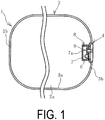
- a pneumatic fender 1 (hereinafter, also fender 1) of the present invention illustrated in FIG. 1 to FIG. 5 includes a fender bladder 2 that is made mainly of rubber and has reinforcing material embedded therein.
- the fender bladder 2 is formed with a cylindrical portion 3a and a bowl-like hemispherical portion 3b on each end of the cylindrical portion 3a in the cylinder axial direction connected thereto.
- a mouth piece metal 4 of the present invention is provided on one of the hemispherical portions 3b.
- the mouth piece metal 4 may also be provided on the hemispherical portion 3b on both sides.
- the mouth piece metal 4 is a recessed cylinder-like fitting.
- the opening of the mouth piece metal 4 to the surface side may be covered by a lid attached by a bolt or the like.
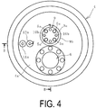
- the mouth piece metal 4 includes a safety valve 6, a communication passage 11 that connects a cavity 2a of the fender bladder 2 to the outside air, and a bladder open/close valve 11a that opens and closes the communication passage 11. Additionally, the mouth piece metal 4 includes a receiving chamber 8 that isolates the safety valve 6 from the cavity 2a, a through hole 7a formed in a dividing wall 7 constituting the receiving chamber 8, an open/close valve 9 that opens and closes the through hole 7a, a receiving chamber communication passage 12 that connects a cavity 8a of the receiving chamber 8 to the outside air, and a receiving chamber open/close valve 12a that opens and closes the receiving chamber communication passage 12.
- the mouth piece metal 4 further includes closed position fixing members 5a and open position fixing members 5b.
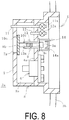
- the receiving chamber 8 is formed extending toward the cavity 2a of the fender bladder 2 from a flat plate 4a on which the safety valve 6 is attached. In other words, the receiving chamber 8 is formed at a position to the back side of the mouth piece metal 4.
- the safety valve 6 is fixed to the flat plate 4a and extends through the flat plate 4a and into the cavity 8a of the receiving chamber 8.
- the communication passage 11 extends through the flat plate 4a and the receiving chamber 8 and terminates in the cavity 2a.
- the receiving chamber communication passage 12 extends through the flat plate 4a and terminates in the cavity 8a of the receiving chamber 8.
- the open/close valve 9 includes a shaft 9c and an outer flange 9a and an inner flange 9b fixed to either end of the shaft 9c.
- the outer flange 9a and the inner flange 9b are in an opposing configuration.
- the shaft 9c extends through the flat plate 4a and can slide freely in the cylinder axial direction of the fender bladder 2.
- the inner flange 9b is disposed in the cavity 8a of the receiving chamber 8.
- the outer flange 9a is disposed outside of the receiving chamber 8 at a position to the surface side of the mouth piece metal 4.
- the open/close valve 9 can slide freely in the direction in which it moves towards and away from the through hole 7a.
- the through hole 7a is open with the open/close valve 9 being fixed to the flat plate 4a at a position in which the through hole 7a is open by the open position fixing members 5b.
- the open position fixing members 5b are disposed outside of the receiving chamber 8 at a position to the surface side of the mouth piece metal 4.
- a seal material 10c is preferably disposed between the opposing surfaces to increase hermeticity.
- the seal material 10c is annular.
- the through hole 7a is closed with the open/close valve 9 being fixed to the flat plate 4a at a position in which the through hole 7a is closed by the closed position fixing members 5a.
- the closed position fixing members 5a are disposed outside of the receiving chamber 8 at a position to the surface side of the mouth piece metal 4.
- the seal material 10c is preferably disposed between the opposing surfaces to increase hermeticity.
- Closing position holes 10a and opening position holes 10b are alternately disposed in the outer flange 9a at intervals in the circumferential direction.
- the closing position holes 10a and the opening position holes 10b extend through the outer flange 9a in the sliding direction of the open/close valve 9.
- the closing position holes 10a are simple through holes and the opening position holes 10b are bolt holes.
- the closed position fixing members 5a are typical fixing bolts.
- the open position fixing members 5b are fixing bolts threaded from the bolt head portion about halfway down in the longitudinal direction.
- the open position fixing members 5b are screwed into the opening position holes 10b formed in the outer flange 9a, the tips of the open position fixing members 5b are brought into contact with the surface of the flat plate 4a, and the opposing surfaces of the inner flange 9b and the flat plate 4a are brought into hermetic contact.
- the closed position fixing members 5a are inserted in the closing position holes 10a formed in the outer flange 9a, the tips of the closed position fixing members 5a are screwed into bolt holes formed in the surface of the flat plate 4a, and the inner flange 9b and the dividing wall 7 (the dividing wall 7 positioned opposing the flat plate 4a) are brought into hermetic contact.
- the cavity 2a is given the predetermined initial internal pressure Pi by being inflated with air or filled with air and fluid (water).
- the pneumatic fender 1 is disposed at the place of use such as a wharf.
- the open/close valve 9 is fixed at a position in which the through hole 7a is open by the open position fixing members 5b. Accordingly, the cavity 2a of the fender bladder 2 and the cavity 8a of the receiving chamber 8 are connected via the through hole 7a and thus the cavities 2a, 8a become equal in internal pressure P.
- the internal pressure of the cavity 8a is also exceeded. This causes the safety valve 6 to open.
- the safety valve 6 functions as per convention to connect the cavity 2a to the outside air, thus reducing the internal pressure P of the cavity 2a to the pressure threshold Pm or less. As a result, damage to the fender bladder 2 can be prevented.
- the open/close valve 9 is fixed at a position in which the through hole 7a is closed by the closed position fixing members 5a.
- the safety valve 6 is isolated from the cavity 2a of the fender bladder 2 by the receiving chamber 8. Accordingly, the safety valve 6 can be safely detached from the mouth piece metal 4 and safely attached to the mouth piece metal 4.
- the safety valve 6 can be detached and attached from an in-use pneumatic fender 1 while in use without bringing the pneumatic fender 1 onto land or a marine vessel.
- the open/close valve 9 thus keeping the through hole 7a closed
- the receiving chamber open/close valve 12a by opening the receiving chamber open/close valve 12a and injecting compressed air into the cavity 8a of the receiving chamber 8 via the receiving chamber communication passage 12, the internal pressure of the cavity 8a can be raised to the pressure threshold Pm.
- a confirmation test of the valve opening pressure of the safety valve 6 can be performed on the pneumatic fender 1 while in use.
- the safety valve 6 can be detached and attached and a confirmation test of the valve opening pressure can be performed on the pneumatic fender 1 while in use.
- the labor and time required for these operations can be greatly reduced, and maintainability can be significantly enhanced.
- FIG. 6 Another embodiment of the mouth piece metal 4 is illustrated in FIG. 6 .
- This mouth piece metal 4 is provided with open position fixing members 5c, which are typical fixing bolts, and an open position fixing member 5d, which is a spacer disposed between the flat plate 4a and the outer flange 9a.
- the open position fixing member 5d is disposed between the flat plate 4a and the outer flange 9a to keep the through hole 7a open.
- the open position fixing members 5c are screwed into the opening position holes 10b formed in the outer flange 9a, the tips of the open position fixing members 5c are brought into contact with the surface of the open position fixing member 5d, which is a spacer, and the opposing surfaces of the inner flange 9b and the flat plate 4a come into hermetic contact.
- the mouth piece metal 4 of this embodiments allows the length of the fixing bolts, i.e. the open position fixing members 5c, to be shortened.
- FIG. 7 Another embodiment of the mouth piece metal 4 is illustrated in FIG. 7 .
- This mouth piece metal 4 is provided with a cylindrical guide member 13 that extends through the flat plate 4a.
- the guide member 13 includes a first end, with its diameter widened into a flange, fixed to the flat plate 4a.
- a second end of the guide member 13 extends to a position partway into the cavity 8a of the receiving chamber 8.
- a guide hole 13a formed in the guide member 13 extends in the cylinder axial direction of the fender bladder 2.
- the shaft 9c that constitutes the open/close valve 9 is inserted into the guide hole 13a.
- the shaft 9c is integrally provided with the outer flange 9a on a first end and the inner flange 9b on a second end.
- the outer peripheral surface of the shaft 9c and the inner peripheral surface of the guide hole 13a are screwed together, and by rotating the shaft 9c, the inner flange 9b (open/close valve 9) moves toward or away from the through hole 7a.
- the inner peripheral surface of the guide hole 13a and the outer peripheral surface of the shaft 9c are in contact with each other with the seal material 10c provided in the space therebetween to provide hermeticity.
- a cover 14 that covers the outer flange 9a is detachably provided on the first end of the guide member 13.
- An engagement portion 14a that engages with the outer flange 9a is provided on the inner side of the cover 14. To open the through hole 7a, the cover 14 is removed from the outer flange 9a and the outer flange 9a together with the shaft 9c are rotated, thus moving the inner flange 9b away from the through hole 7a.
- the cover 14 which covers the outer flange 9a, prevents any unintentional operation of the open/close valve 9. As illustrated in FIG. 7 , when the through hole 7a is closed, the inner flange 9b disposed on the second end of the shaft 9c is brought into contact with the surface of the second end of the guide member 13. In this embodiment, the mating guide member 13 and the shaft 9c function as the open position fixing member.
- the cover 14 is removed from the outer flange 9a and the outer flange 9a together with the shaft 9c are rotated (the shaft 9c is rotated in the direction opposite to when opening the through hole 7a), thus moving the inner flange 9b (open/close valve 9) toward the through hole 7a.
- This brings the opposing surfaces of the inner flange 9c and the dividing wall 7 into hermetic contact.
- the open/close valve 9 can be easily fixed at a position in which the through hole 7a is closed.
- the mating guide member 13 and the shaft 9c function as the closed position fixing member.
- the stroke length of the open/close valve 9 (distance traveled in the axial direction) required to open and close the through hole 7a can be changed in accordance with the position of the second end of the guide member 13 (the length the guide member 13 extends into the cavity 8a of the receiving chamber 8). Accordingly, the stroke length of the open/close valve 9 can be easily minimized.
Landscapes
- Engineering & Computer Science (AREA)
- General Engineering & Computer Science (AREA)
- Mechanical Engineering (AREA)
- Ocean & Marine Engineering (AREA)
- Environmental & Geological Engineering (AREA)
- Civil Engineering (AREA)
- Structural Engineering (AREA)
- Chemical & Material Sciences (AREA)
- Combustion & Propulsion (AREA)
- Safety Valves (AREA)
- Body Structure For Vehicles (AREA)
Claims (6)
- Mundstückmetall (4) für einen pneumatischen Fender (1), das an einem schalenförmigen halbkugelförmigen Abschnitt befestigt werden kann, der eine Fenderblase (2) bildet, wobei das Mundstückmetall (2) umfasst:ein Sicherheitsventil (6), das sich öffnet, wenn der Innendruck eines Hohlraums der Fenderblase (2) einen Druckschwellenwert erreicht, um den Hohlraum der Fenderblase mit der Außenluft zu verbinden und den Innendruck zu reduzieren, undeinen Verbindungsdurchlass, der den Hohlraum der Fenderblase (2) mit der Außenluft verbindet; undein Blasenöffnungs-/-schließventil (11a), das den Verbindungsdurchlass öffnet und schließt;eine Aufnahmekammer, die das Sicherheitsventil (6) vom Hohlraum der Fenderblase (2) trennt,dadurch gekennzeichnet, dass das Mundstückmetall (4) ferner beinhaltet:eine Durchgangsöffnung (7a), die einen Hohlraum (8a) der Aufnahmekammer (8) mit dem Hohlraum (2a) der Fenderblase (2) verbindet,wobei die Durchgangsöffnung (7a) an einer Trennwand (7) ausgebildet ist, die die Aufnahmekammer (8) bildet,ein Öffnungs-/Schließventil (9), das die Durchgangsöffnung (7a) öffnet und schließt,ein Befestigungselement (5a) in geschlossener Position, das das Öffnungs-/Schließventil (9) in einer Position fixiert, in der die Durchgangsöffnung (7a) geschlossen ist,ein Befestigungselement (5b) in offener Position, das das Öffnungs-/Schließventil (9) in einer Position fixiert, in der die Durchgangsöffnung (7a) geöffnet ist,einen Verbindungsdurchlass (12) der Aufnahmekammer, der den Hohlraum (7a) der Aufnahmekammer (8) mit der Außenluft verbindet, undein Öffnungs-/Schließventil (12a) der Aufnahmekammer, das den Verbindungsdurchlass (12) der Aufnahmekammer öffnet und schließt, undwobei mindestens ein Teil des Befestigungselements (5a) in geschlossener Position und des Befestigungselements (5b) in offener Position außerhalb der Aufnahmekammer (8) in einer Position an einer Oberflächenseite des Mundstückmetalls (4) angeordnet ist.
- Mundstückmetall (4) für einen pneumatischen Fender (1) nach Anspruch 1, wobei das Öffnungs-/Schließventil (9) umfasst:einen in der Aufnahmekammer (8) angeordneten Innenflansch (9b),einen Außenflansch (9a), der außerhalb der Aufnahmekammer (8) in einer Position an der Oberflächenseite des Mundstückmetalls (4) angeordnet ist, undeine Welle (9c) mit Enden, an denen der Innenflansch (9b) und der Außenflansch (9a) gegenüberliegend befestigt sind; wobei das Öffnungs-/Schließventil (12) in einer Richtung zur Durchgangsöffnung (7a) hin oder von ihr weg verschiebbar ist; undwobei das Öffnungs-/Schließventil (12) die Durchgangsöffnung (7a) über den Innenflansch (9b) öffnet und schließt.
- Mundstückmetall (4) für einen pneumatischen Fender (1) nach Anspruch 1 oder 2,
wobei ein vorzugsweise ringförmiges Dichtungsmaterial (10c) zwischen gegenüberliegenden Oberflächen des Öffnungs-/Schließventils (9) und der Trennwand (7) angeordnet ist,
das an einer Position befestigt ist, um die Durchgangsöffnung (7a) abzudichten, wenn die Durchgangsöffnung (7a) geschlossen ist, und
nicht abzudichten, wenn die Durchgangsöffnung (7a) geöffnet ist. - Pneumatischer Fender (1), umfassend:eine Fenderblase (2), die einen zylindrischen Abschnitt (3a) und schalenförmige halbkugelförmige Abschnitte (3b) aufweist, die mit jedem Ende des zylindrischen Abschnitts (3a) verbunden sind,ein Mundstückmetall nach Anspruch 1, das auf mindestens einem der halbkugelförmigen Abschnitte (3b) angeordnet ist.
- Pneumatischer Fender (1), umfassend:eine Fenderblase (2), die einen zylindrischen Abschnitt (3a) und schalenförmige halbkugelförmige Abschnitte (3b) aufweist, die mit jedem Ende des zylindrischen Abschnitts (3a) verbunden sind,ein Mundstückmetall nach Anspruch 2, das auf mindestens einem der hemisphärischen Abschnitte (3b) angeordnet ist.
- Pneumatischer Fender (1), umfassend:eine Fenderblase (2), die einen zylindrischen Abschnitt (3a) und schalenförmige halbkugelförmige Abschnitte (3b) aufweist, die mit jedem Ende des zylindrischen Abschnitts (3a) verbunden sind,ein Mundstückmetall nach Anspruch 3, das auf mindestens einem der halbkugelförmigen Abschnitte (3b) angeordnet ist.
Applications Claiming Priority (2)
| Application Number | Priority Date | Filing Date | Title |
|---|---|---|---|
| JP2014071326 | 2014-03-31 | ||
| PCT/JP2015/058951 WO2015151938A1 (ja) | 2014-03-31 | 2015-03-24 | 空気式防舷材および空気式防舷材用口金具 |
Publications (3)
| Publication Number | Publication Date |
|---|---|
| EP3128082A1 EP3128082A1 (de) | 2017-02-08 |
| EP3128082A4 EP3128082A4 (de) | 2017-11-22 |
| EP3128082B1 true EP3128082B1 (de) | 2019-04-24 |
Family
ID=54240265
Family Applications (1)
| Application Number | Title | Priority Date | Filing Date |
|---|---|---|---|
| EP15773754.5A Active EP3128082B1 (de) | 2014-03-31 | 2015-03-24 | Pneumatisches spritzblech und mundstück für pneumatisches spritzblech |
Country Status (6)
| Country | Link |
|---|---|
| US (1) | US9816241B2 (de) |
| EP (1) | EP3128082B1 (de) |
| JP (1) | JP6520921B2 (de) |
| KR (1) | KR102352626B1 (de) |
| CN (1) | CN106029986B (de) |
| WO (1) | WO2015151938A1 (de) |
Families Citing this family (6)
| Publication number | Priority date | Publication date | Assignee | Title |
|---|---|---|---|---|
| JP6291968B2 (ja) * | 2014-03-31 | 2018-03-14 | 横浜ゴム株式会社 | 空気式防舷材および空気式防舷材用口金具 |
| US10429647B2 (en) * | 2016-06-10 | 2019-10-01 | Facebook Technologies, Llc | Focus adjusting virtual reality headset |
| KR101882378B1 (ko) | 2018-05-17 | 2018-07-26 | (주)화승엑스윌 | 공압식 방충재용 개폐밸브 |
| JP7180386B2 (ja) * | 2019-01-09 | 2022-11-30 | 横浜ゴム株式会社 | 空気式防舷材 |
| KR102162839B1 (ko) | 2020-08-06 | 2020-10-07 | (주)화승엑스윌 | 공압식 방충재용 복합밸브 |
| KR102295302B1 (ko) | 2021-02-23 | 2021-08-31 | (주)화승코퍼레이션 | 공압식 방충재용 복합장치 |
Family Cites Families (19)
| Publication number | Priority date | Publication date | Assignee | Title |
|---|---|---|---|---|
| DE2316503B2 (de) * | 1973-04-03 | 1977-09-15 | Ausscheidung in: 23 65 558 Messerschmitt-Bölkow-Blohm GmbH, 8000 München | Stossfaenger fuer fahrzeuge |
| US4176858A (en) * | 1974-01-04 | 1979-12-04 | Safety Consultants | Energy absorbing bumper system |
| US4099759A (en) * | 1976-05-18 | 1978-07-11 | Safety Consultants | Energy absorbing bumper system |
| JPS6071390A (ja) * | 1983-09-28 | 1985-04-23 | Yokohama Rubber Co Ltd:The | フオ−ム充填フエンダ−及びその製造方法 |
| JP3786526B2 (ja) * | 1998-09-09 | 2006-06-14 | 横浜ゴム株式会社 | 空気式防舷材の気密テスト方法及び気密テスト装置 |
| US6126214A (en) * | 1999-07-26 | 2000-10-03 | Kim; Sun Young | Air bumper |
| JP2002115768A (ja) * | 2000-10-06 | 2002-04-19 | Asuka Kogyo Kk | 安全弁用切換弁 |
| JP4413458B2 (ja) * | 2001-10-25 | 2010-02-10 | 横浜ゴム株式会社 | 空気式防舷材 |
| JP3933438B2 (ja) | 2001-10-29 | 2007-06-20 | 横浜ゴム株式会社 | 空気式防舷材 |
| CN1285484C (zh) * | 2004-01-19 | 2006-11-22 | 孙菊香 | 船用充气橡胶靠球及其生产工艺 |
| CN200985089Y (zh) * | 2006-11-28 | 2007-12-05 | 闫海军 | 填充式橡胶护舷 |
| CN201420256Y (zh) * | 2009-05-25 | 2010-03-10 | 青岛天盾橡胶有限公司 | 一种超大型漂浮护舷 |
| CN201588192U (zh) * | 2009-10-27 | 2010-09-22 | 钟爱民 | 复合式护舷 |
| CA2801411C (en) * | 2010-06-11 | 2014-07-22 | The Yokohama Rubber Co., Ltd. | Pneumatic fender management system |
| JP5077471B1 (ja) | 2011-09-30 | 2012-11-21 | 横浜ゴム株式会社 | 空気式防舷材用のセンサ収納容器および空気式防舷材 |
| JP5565434B2 (ja) * | 2012-04-27 | 2014-08-06 | 横浜ゴム株式会社 | 空気式防舷材 |
| CN104641044B (zh) * | 2012-10-11 | 2016-06-08 | 横滨橡胶株式会社 | 充气式护舷材 |
| JP6136556B2 (ja) * | 2013-05-10 | 2017-05-31 | 横浜ゴム株式会社 | 縦型空気式防舷材 |
| JP6291968B2 (ja) * | 2014-03-31 | 2018-03-14 | 横浜ゴム株式会社 | 空気式防舷材および空気式防舷材用口金具 |
-
2015
- 2015-03-24 US US15/301,190 patent/US9816241B2/en active Active
- 2015-03-24 CN CN201580010217.3A patent/CN106029986B/zh active Active
- 2015-03-24 EP EP15773754.5A patent/EP3128082B1/de active Active
- 2015-03-24 WO PCT/JP2015/058951 patent/WO2015151938A1/ja not_active Ceased
- 2015-03-24 JP JP2016511568A patent/JP6520921B2/ja active Active
- 2015-03-24 KR KR1020167022679A patent/KR102352626B1/ko active Active
Non-Patent Citations (1)
| Title |
|---|
| None * |
Also Published As
| Publication number | Publication date |
|---|---|
| US9816241B2 (en) | 2017-11-14 |
| EP3128082A4 (de) | 2017-11-22 |
| CN106029986B (zh) | 2017-09-22 |
| JP6520921B2 (ja) | 2019-05-29 |
| US20170016195A1 (en) | 2017-01-19 |
| CN106029986A (zh) | 2016-10-12 |
| KR20160138386A (ko) | 2016-12-05 |
| JPWO2015151938A1 (ja) | 2017-04-13 |
| KR102352626B1 (ko) | 2022-01-18 |
| EP3128082A1 (de) | 2017-02-08 |
| WO2015151938A1 (ja) | 2015-10-08 |
Similar Documents
| Publication | Publication Date | Title |
|---|---|---|
| EP3128082B1 (de) | Pneumatisches spritzblech und mundstück für pneumatisches spritzblech | |
| US9327809B2 (en) | Salvage container and salvaging method | |
| JP2012524875A (ja) | ピストンステムの飛び出しを制御しうる安全装置を備えたガスシリンダアクチュエータ | |
| EP3128081B1 (de) | Pneumatisches spritzblech und mundstück für pneumatisches spritzblech | |
| CN104482280B (zh) | 一种飞机气密舱的排水方法 | |
| JP2017508117A5 (de) | ||
| EP2762850A1 (de) | Sensorgehäusebehälter für einen pneumatischen fender und pneumatischer fender | |
| CN107178676B (zh) | 一种自锁式应急用管路防漏装置及方法 | |
| JP2015151135A (ja) | キャップ | |
| CN109915685A (zh) | 一种风洞管体端盖 | |
| KR200479985Y1 (ko) | 밀폐형 리벳 플러그 | |
| KR100294798B1 (ko) | 선박침몰 방지장치 | |
| CN209782007U (zh) | 一种风洞管体端盖 | |
| KR101517721B1 (ko) | 자동차의 트랜스 미션 오일의 배출구조 | |
| CN105508727A (zh) | 阀门保护箱 | |
| RU2621930C1 (ru) | Дренажное устройство | |
| CN211893609U (zh) | 一种活塞式潜艇舱门 | |
| KR200472374Y1 (ko) | 선박용 압축공기탱크의 드레인수 배출 호퍼 | |
| CN108194652A (zh) | 一种新型小流量气体按钮阀 | |
| WO2016170923A1 (ja) | 横型空気式防舷材用の保護カバーおよび横型空気式防舷材並びに横型空気式防舷材の使用方法 | |
| CN106895131B (zh) | 密封通气装置及包括其的设备 | |
| ITMI20101706A1 (it) | Tappo sfiatatoio, particolarmente per celle elettrolitiche di accumulatori elettrici e simili. | |
| CN104653546A (zh) | 一种火车制动器气缸 | |
| JP2016204908A (ja) | 縦型空気式防舷材用の保護カバーおよび縦型空気式防舷材並びに縦型空気式防舷材の使用方法 | |
| KR20120043548A (ko) | 차량의 캡 틸트 유압 실린더 |
Legal Events
| Date | Code | Title | Description |
|---|---|---|---|
| STAA | Information on the status of an ep patent application or granted ep patent |
Free format text: STATUS: THE INTERNATIONAL PUBLICATION HAS BEEN MADE |
|
| PUAI | Public reference made under article 153(3) epc to a published international application that has entered the european phase |
Free format text: ORIGINAL CODE: 0009012 |
|
| STAA | Information on the status of an ep patent application or granted ep patent |
Free format text: STATUS: REQUEST FOR EXAMINATION WAS MADE |
|
| 17P | Request for examination filed |
Effective date: 20161031 |
|
| AK | Designated contracting states |
Kind code of ref document: A1 Designated state(s): AL AT BE BG CH CY CZ DE DK EE ES FI FR GB GR HR HU IE IS IT LI LT LU LV MC MK MT NL NO PL PT RO RS SE SI SK SM TR |
|
| AX | Request for extension of the european patent |
Extension state: BA ME |
|
| DAV | Request for validation of the european patent (deleted) | ||
| DAX | Request for extension of the european patent (deleted) | ||
| A4 | Supplementary search report drawn up and despatched |
Effective date: 20171023 |
|
| RIC1 | Information provided on ipc code assigned before grant |
Ipc: E02B 3/26 20060101AFI20171017BHEP Ipc: B63B 59/02 20060101ALI20171017BHEP |
|
| GRAP | Despatch of communication of intention to grant a patent |
Free format text: ORIGINAL CODE: EPIDOSNIGR1 |
|
| STAA | Information on the status of an ep patent application or granted ep patent |
Free format text: STATUS: GRANT OF PATENT IS INTENDED |
|
| INTG | Intention to grant announced |
Effective date: 20181207 |
|
| GRAS | Grant fee paid |
Free format text: ORIGINAL CODE: EPIDOSNIGR3 |
|
| GRAA | (expected) grant |
Free format text: ORIGINAL CODE: 0009210 |
|
| STAA | Information on the status of an ep patent application or granted ep patent |
Free format text: STATUS: THE PATENT HAS BEEN GRANTED |
|
| AK | Designated contracting states |
Kind code of ref document: B1 Designated state(s): AL AT BE BG CH CY CZ DE DK EE ES FI FR GB GR HR HU IE IS IT LI LT LU LV MC MK MT NL NO PL PT RO RS SE SI SK SM TR |
|
| REG | Reference to a national code |
Ref country code: GB Ref legal event code: FG4D |
|
| REG | Reference to a national code |
Ref country code: CH Ref legal event code: EP |
|
| REG | Reference to a national code |
Ref country code: AT Ref legal event code: REF Ref document number: 1124316 Country of ref document: AT Kind code of ref document: T Effective date: 20190515 Ref country code: IE Ref legal event code: FG4D |
|
| REG | Reference to a national code |
Ref country code: DE Ref legal event code: R096 Ref document number: 602015028950 Country of ref document: DE |
|
| REG | Reference to a national code |
Ref country code: NL Ref legal event code: FP |
|
| REG | Reference to a national code |
Ref country code: SE Ref legal event code: TRGR |
|
| REG | Reference to a national code |
Ref country code: LT Ref legal event code: MG4D |
|
| REG | Reference to a national code |
Ref country code: NO Ref legal event code: T2 Effective date: 20190424 |
|
| PG25 | Lapsed in a contracting state [announced via postgrant information from national office to epo] |
Ref country code: HR Free format text: LAPSE BECAUSE OF FAILURE TO SUBMIT A TRANSLATION OF THE DESCRIPTION OR TO PAY THE FEE WITHIN THE PRESCRIBED TIME-LIMIT Effective date: 20190424 Ref country code: LT Free format text: LAPSE BECAUSE OF FAILURE TO SUBMIT A TRANSLATION OF THE DESCRIPTION OR TO PAY THE FEE WITHIN THE PRESCRIBED TIME-LIMIT Effective date: 20190424 Ref country code: ES Free format text: LAPSE BECAUSE OF FAILURE TO SUBMIT A TRANSLATION OF THE DESCRIPTION OR TO PAY THE FEE WITHIN THE PRESCRIBED TIME-LIMIT Effective date: 20190424 Ref country code: AL Free format text: LAPSE BECAUSE OF FAILURE TO SUBMIT A TRANSLATION OF THE DESCRIPTION OR TO PAY THE FEE WITHIN THE PRESCRIBED TIME-LIMIT Effective date: 20190424 Ref country code: PT Free format text: LAPSE BECAUSE OF FAILURE TO SUBMIT A TRANSLATION OF THE DESCRIPTION OR TO PAY THE FEE WITHIN THE PRESCRIBED TIME-LIMIT Effective date: 20190824 Ref country code: FI Free format text: LAPSE BECAUSE OF FAILURE TO SUBMIT A TRANSLATION OF THE DESCRIPTION OR TO PAY THE FEE WITHIN THE PRESCRIBED TIME-LIMIT Effective date: 20190424 |
|
| PG25 | Lapsed in a contracting state [announced via postgrant information from national office to epo] |
Ref country code: BG Free format text: LAPSE BECAUSE OF FAILURE TO SUBMIT A TRANSLATION OF THE DESCRIPTION OR TO PAY THE FEE WITHIN THE PRESCRIBED TIME-LIMIT Effective date: 20190724 Ref country code: GR Free format text: LAPSE BECAUSE OF FAILURE TO SUBMIT A TRANSLATION OF THE DESCRIPTION OR TO PAY THE FEE WITHIN THE PRESCRIBED TIME-LIMIT Effective date: 20190725 Ref country code: LV Free format text: LAPSE BECAUSE OF FAILURE TO SUBMIT A TRANSLATION OF THE DESCRIPTION OR TO PAY THE FEE WITHIN THE PRESCRIBED TIME-LIMIT Effective date: 20190424 Ref country code: PL Free format text: LAPSE BECAUSE OF FAILURE TO SUBMIT A TRANSLATION OF THE DESCRIPTION OR TO PAY THE FEE WITHIN THE PRESCRIBED TIME-LIMIT Effective date: 20190424 Ref country code: RS Free format text: LAPSE BECAUSE OF FAILURE TO SUBMIT A TRANSLATION OF THE DESCRIPTION OR TO PAY THE FEE WITHIN THE PRESCRIBED TIME-LIMIT Effective date: 20190424 |
|
| REG | Reference to a national code |
Ref country code: AT Ref legal event code: MK05 Ref document number: 1124316 Country of ref document: AT Kind code of ref document: T Effective date: 20190424 |
|
| PG25 | Lapsed in a contracting state [announced via postgrant information from national office to epo] |
Ref country code: IS Free format text: LAPSE BECAUSE OF FAILURE TO SUBMIT A TRANSLATION OF THE DESCRIPTION OR TO PAY THE FEE WITHIN THE PRESCRIBED TIME-LIMIT Effective date: 20190824 |
|
| REG | Reference to a national code |
Ref country code: DE Ref legal event code: R097 Ref document number: 602015028950 Country of ref document: DE |
|
| PG25 | Lapsed in a contracting state [announced via postgrant information from national office to epo] |
Ref country code: SK Free format text: LAPSE BECAUSE OF FAILURE TO SUBMIT A TRANSLATION OF THE DESCRIPTION OR TO PAY THE FEE WITHIN THE PRESCRIBED TIME-LIMIT Effective date: 20190424 Ref country code: RO Free format text: LAPSE BECAUSE OF FAILURE TO SUBMIT A TRANSLATION OF THE DESCRIPTION OR TO PAY THE FEE WITHIN THE PRESCRIBED TIME-LIMIT Effective date: 20190424 Ref country code: CZ Free format text: LAPSE BECAUSE OF FAILURE TO SUBMIT A TRANSLATION OF THE DESCRIPTION OR TO PAY THE FEE WITHIN THE PRESCRIBED TIME-LIMIT Effective date: 20190424 Ref country code: DK Free format text: LAPSE BECAUSE OF FAILURE TO SUBMIT A TRANSLATION OF THE DESCRIPTION OR TO PAY THE FEE WITHIN THE PRESCRIBED TIME-LIMIT Effective date: 20190424 Ref country code: EE Free format text: LAPSE BECAUSE OF FAILURE TO SUBMIT A TRANSLATION OF THE DESCRIPTION OR TO PAY THE FEE WITHIN THE PRESCRIBED TIME-LIMIT Effective date: 20190424 Ref country code: AT Free format text: LAPSE BECAUSE OF FAILURE TO SUBMIT A TRANSLATION OF THE DESCRIPTION OR TO PAY THE FEE WITHIN THE PRESCRIBED TIME-LIMIT Effective date: 20190424 |
|
| PG25 | Lapsed in a contracting state [announced via postgrant information from national office to epo] |
Ref country code: SM Free format text: LAPSE BECAUSE OF FAILURE TO SUBMIT A TRANSLATION OF THE DESCRIPTION OR TO PAY THE FEE WITHIN THE PRESCRIBED TIME-LIMIT Effective date: 20190424 |
|
| PLBE | No opposition filed within time limit |
Free format text: ORIGINAL CODE: 0009261 |
|
| STAA | Information on the status of an ep patent application or granted ep patent |
Free format text: STATUS: NO OPPOSITION FILED WITHIN TIME LIMIT |
|
| PG25 | Lapsed in a contracting state [announced via postgrant information from national office to epo] |
Ref country code: TR Free format text: LAPSE BECAUSE OF FAILURE TO SUBMIT A TRANSLATION OF THE DESCRIPTION OR TO PAY THE FEE WITHIN THE PRESCRIBED TIME-LIMIT Effective date: 20190424 |
|
| 26N | No opposition filed |
Effective date: 20200127 |
|
| PG25 | Lapsed in a contracting state [announced via postgrant information from national office to epo] |
Ref country code: SI Free format text: LAPSE BECAUSE OF FAILURE TO SUBMIT A TRANSLATION OF THE DESCRIPTION OR TO PAY THE FEE WITHIN THE PRESCRIBED TIME-LIMIT Effective date: 20190424 |
|
| REG | Reference to a national code |
Ref country code: DE Ref legal event code: R119 Ref document number: 602015028950 Country of ref document: DE |
|
| PG25 | Lapsed in a contracting state [announced via postgrant information from national office to epo] |
Ref country code: MC Free format text: LAPSE BECAUSE OF FAILURE TO SUBMIT A TRANSLATION OF THE DESCRIPTION OR TO PAY THE FEE WITHIN THE PRESCRIBED TIME-LIMIT Effective date: 20190424 |
|
| REG | Reference to a national code |
Ref country code: CH Ref legal event code: PL |
|
| REG | Reference to a national code |
Ref country code: BE Ref legal event code: MM Effective date: 20200331 |
|
| PG25 | Lapsed in a contracting state [announced via postgrant information from national office to epo] |
Ref country code: LU Free format text: LAPSE BECAUSE OF NON-PAYMENT OF DUE FEES Effective date: 20200324 |
|
| PG25 | Lapsed in a contracting state [announced via postgrant information from national office to epo] |
Ref country code: DE Free format text: LAPSE BECAUSE OF NON-PAYMENT OF DUE FEES Effective date: 20201001 Ref country code: LI Free format text: LAPSE BECAUSE OF NON-PAYMENT OF DUE FEES Effective date: 20200331 Ref country code: IE Free format text: LAPSE BECAUSE OF NON-PAYMENT OF DUE FEES Effective date: 20200324 Ref country code: CH Free format text: LAPSE BECAUSE OF NON-PAYMENT OF DUE FEES Effective date: 20200331 |
|
| PG25 | Lapsed in a contracting state [announced via postgrant information from national office to epo] |
Ref country code: BE Free format text: LAPSE BECAUSE OF NON-PAYMENT OF DUE FEES Effective date: 20200331 |
|
| PG25 | Lapsed in a contracting state [announced via postgrant information from national office to epo] |
Ref country code: MT Free format text: LAPSE BECAUSE OF FAILURE TO SUBMIT A TRANSLATION OF THE DESCRIPTION OR TO PAY THE FEE WITHIN THE PRESCRIBED TIME-LIMIT Effective date: 20190424 Ref country code: CY Free format text: LAPSE BECAUSE OF FAILURE TO SUBMIT A TRANSLATION OF THE DESCRIPTION OR TO PAY THE FEE WITHIN THE PRESCRIBED TIME-LIMIT Effective date: 20190424 |
|
| PG25 | Lapsed in a contracting state [announced via postgrant information from national office to epo] |
Ref country code: MK Free format text: LAPSE BECAUSE OF FAILURE TO SUBMIT A TRANSLATION OF THE DESCRIPTION OR TO PAY THE FEE WITHIN THE PRESCRIBED TIME-LIMIT Effective date: 20190424 |
|
| P01 | Opt-out of the competence of the unified patent court (upc) registered |
Effective date: 20230512 |
|
| PGFP | Annual fee paid to national office [announced via postgrant information from national office to epo] |
Ref country code: NL Payment date: 20260213 Year of fee payment: 12 |
|
| PGFP | Annual fee paid to national office [announced via postgrant information from national office to epo] |
Ref country code: SE Payment date: 20260211 Year of fee payment: 12 |
|
| PGFP | Annual fee paid to national office [announced via postgrant information from national office to epo] |
Ref country code: GB Payment date: 20260202 Year of fee payment: 12 |
|
| PGFP | Annual fee paid to national office [announced via postgrant information from national office to epo] |
Ref country code: NO Payment date: 20260310 Year of fee payment: 12 |
|
| PGFP | Annual fee paid to national office [announced via postgrant information from national office to epo] |
Ref country code: IT Payment date: 20260220 Year of fee payment: 12 |
|
| PGFP | Annual fee paid to national office [announced via postgrant information from national office to epo] |
Ref country code: FR Payment date: 20260309 Year of fee payment: 12 |