EP3128097A1 - Élément isolant et procédé d'isolation d'une fenêtre de toit - Google Patents
Élément isolant et procédé d'isolation d'une fenêtre de toit Download PDFInfo
- Publication number
- EP3128097A1 EP3128097A1 EP16181997.4A EP16181997A EP3128097A1 EP 3128097 A1 EP3128097 A1 EP 3128097A1 EP 16181997 A EP16181997 A EP 16181997A EP 3128097 A1 EP3128097 A1 EP 3128097A1
- Authority
- EP
- European Patent Office
- Prior art keywords
- insulating
- frame piece
- frame
- insulating element
- insulating member
- Prior art date
- Legal status (The legal status is an assumption and is not a legal conclusion. Google has not performed a legal analysis and makes no representation as to the accuracy of the status listed.)
- Granted
Links
Images


Classifications
-
- E—FIXED CONSTRUCTIONS
- E04—BUILDING
- E04D—ROOF COVERINGS; SKY-LIGHTS; GUTTERS; ROOF-WORKING TOOLS
- E04D13/00—Special arrangements or devices in connection with roof coverings; Protection against birds; Roof drainage ; Sky-lights
- E04D13/03—Sky-lights; Domes; Ventilating sky-lights
- E04D13/0305—Supports or connecting means for sky-lights of flat or domed shape
- E04D13/031—Supports or connecting means for sky-lights of flat or domed shape characterised by a frame for connection to an inclined roof
-
- E—FIXED CONSTRUCTIONS
- E04—BUILDING
- E04D—ROOF COVERINGS; SKY-LIGHTS; GUTTERS; ROOF-WORKING TOOLS
- E04D13/00—Special arrangements or devices in connection with roof coverings; Protection against birds; Roof drainage ; Sky-lights
- E04D13/03—Sky-lights; Domes; Ventilating sky-lights
-
- E—FIXED CONSTRUCTIONS
- E04—BUILDING
- E04B—GENERAL BUILDING CONSTRUCTIONS; WALLS, e.g. PARTITIONS; ROOFS; FLOORS; CEILINGS; INSULATION OR OTHER PROTECTION OF BUILDINGS
- E04B7/00—Roofs; Roof construction with regard to insulation
- E04B7/18—Special structures in or on roofs, e.g. dormer windows
-
- E—FIXED CONSTRUCTIONS
- E04—BUILDING
- E04D—ROOF COVERINGS; SKY-LIGHTS; GUTTERS; ROOF-WORKING TOOLS
- E04D13/00—Special arrangements or devices in connection with roof coverings; Protection against birds; Roof drainage ; Sky-lights
- E04D13/03—Sky-lights; Domes; Ventilating sky-lights
- E04D13/035—Sky-lights; Domes; Ventilating sky-lights characterised by having movable parts
-
- E—FIXED CONSTRUCTIONS
- E06—DOORS, WINDOWS, SHUTTERS, OR ROLLER BLINDS IN GENERAL; LADDERS
- E06B—FIXED OR MOVABLE CLOSURES FOR OPENINGS IN BUILDINGS, VEHICLES, FENCES OR LIKE ENCLOSURES IN GENERAL, e.g. DOORS, WINDOWS, BLINDS, GATES
- E06B1/00—Border constructions of openings in walls, floors, or ceilings; Frames to be rigidly mounted in such openings
- E06B1/62—Tightening or covering joints between the border of openings and the frame or between contiguous frames
Definitions
- the present invention relates to an insulating member for insulating a roof window comprising a stationary rectangular frame with top, bottom, and side frame pieces surrounding an opening, each frame piece having a length, an inner side facing the opening, an outer side opposite the inner side, an interior side interconnecting the inner and outer sides and adapted for facing the interior of a building, and an exterior side opposite the interior side, said insulating member having an elongate shape with a length corresponding substantially to the length of said top and bottom frame pieces or to the length of said side pieces, and a pre-defined cross-section.
- the invention further relates to a method for insulating a roof window.
- an insulating member comprising a first insulating element and a second insulating element which, in a supply condition, are interconnected at a predefined separation zone extending between a first side of the interconnected insulating member and a second side opposite to the first side and along the length of said insulating member, the first insulating element being adapted for insulating a first frame piece of the window by, in an installed condition, being arranged adjacent to the outer side of the first frame piece with an abutment side of said first insulating element facing the frame, and the second insulating element being adapted for insulating a second frame piece of the window, which is opposite to the first frame piece, by, in an installed condition, being arranged adjacent to the outer side of the second frame piece with an abutment side of said second insulating element facing the frame.
- the insulating elements may remain interconnected in one piece up until installation, meaning that fewer components have to be handled before insulating the roof window, thereby making the installation work easier.
- each insulating element may be connected to the other at its abutment side or a portion of its abutment side, i.e. the abutment side is exposed by the separation, or it may be connected at another surface, such that the abutment side forms part of the exposed surface of the insulating member.
- the first insulating element is adapted for insulating the top frame piece of the window and the second insulating element is adapted for insulating the bottom frame piece of the window.
- Such embodiments are advantageous because insulating elements adapted for insulating the top and bottom frame pieces often have different cross-sectional shapes due to the different requirements for these insulating elements, and by having them as one insulating member it is ensured that one of each will be available at installation.
- the interconnection between the first and second insulating elements may be provided by fusing the two insulating elements together, e.g. by chemically or thermally softening the material at part of the surface of the insulating elements such that they can be merged together, or by using fastening means, such as welds, adhesives, clamps, hook-and-loop, etc., or a combination thereof.
- the insulating member is moulded or extruded in one piece.
- the interconnection between the first and second insulating elements is provided by a portion of the insulating member which is adapted for being cut or broken to separate the insulating elements, thereby serving as the separation zone.
- simultaneous manufacturing of the first and second insulating elements has the additional advantage that the need for an extra molding or extrusion process is avoided, thereby lowering production costs.
- the separation zone should be understood as a narrow zone or plane extending through the insulating member to allow predetermined separation. In the simplest embodiments it may be provided by external markings showing the worker where to cut the insulating member to separate the first and second insulating elements. However, in some embodiments the insulating member is provided with a weakening of the interconnection between the first and second insulating elements at the separation zone. The weakening may be realized by the material of the separation zone or the fastening means being weak compared to the material of the first and second insulating elements, such that when pulled or wringed apart the insulating member will separate at the separation zone.
- Structural weakenings of the material at the separation zone can be created either during manufacture of the insulating member by creating the insulating member with less material at the separation zone, or subsequently by removing or cutting part of the material at the separation zone.
- the width between the abutment side and an opposite side of the first and/or second insulating elements decreases over at least part of the height of the insulating element, wherein the height of an insulating element is defined as the direction which, when said insulating element is arranged in its installed position, extends from the interior to the exterior side, such that said insulating element has a maximum width at the side adapted for facing the interior. It is noted that the heights are defined by the orientation of the insulating elements relative to the window in the installed condition, and that in the supply condition the height direction of each insulating element may point in different directions depending on how the first and second insulating elements are interconnected.
- the insulating elements By shaping the insulating elements in this way they can be made to follow the shape of flashing- and cover members typically used on the outer and exterior sides of the roof window. This can be advantageous as particularly the flashing might be subjected to heavy loads during installation and subsequent work on the roof and the support provided by the insulating element fitting closely underneath helps the flashing withstand such pressure in addition to improving insulation by filling the cavity below the flashing members.
- the insulating member may in principle be made from any thermally insulating material, but it is preferably made from a thermally insulating material which is also elastic and/or compressible, such as moulded or extruded polymer foams, e.g. foams made from polystyrene, polyethylene, polyvinyl chloride, or polyurethane.
- a thermally insulating material which is also elastic and/or compressible, such as moulded or extruded polymer foams, e.g. foams made from polystyrene, polyethylene, polyvinyl chloride, or polyurethane.
- the first and/or second insulating elements comprise one or more secondary separation zones.
- Said secondary separation zones being adapted for allowing an adaptation of the shape of the insulating elements, e.g. according to an installation depth and/or angle of the window. This means that the shape of the insulating element can be easily modified to meet the requirements of certain installation conditions, since the predefined secondary separation zones can be used to indicate where to remove superfluous material.
- the secondary separation zones can be realized in the same way as the separation zone between the first and the second insulating elements described above, and two or more ways of realizing the separation zones may be used in one insulating member.
- the first and/or second insulating elements comprise an adhesive arranged on the abutment side and/or another side of the insulating element.
- Such an adhesive may further facilitate installation, as it may be used for at least temporary fastening of the insulating element to a fixed structure, such as the stationary window frame or the roof structure, ensuring that the insulating element will stay in place at least during installation.
- adhesives may additionally fulfill the purpose as means for at least temporary fastening to the roof structure or the frame of the roof window during construction.
- the adhesive is, in the supply condition, protected by a cover strip.
- the cover strip may additionally serve as a surface on which the installation instructions can be printed, ensuring that they will not be separated from the insulating member before installation.
- the first and/or second insulating elements comprise a sealing element projecting out from the abutment side of the insulating element, said sealing element being adapted for, in the installed condition, being arranged overlapping the frame piece at the exterior side of the frame piece.
- the roof window will generally further comprise an exterior cover on top of the stationary frame to protect it from the weather.
- the first and/or second insulating elements comprise a guide abutment projecting out in the height direction, such that it, in the installed condition, extends away from the frame in a direction substantially perpendicular to the frame towards the exterior.
- the exterior cover may be aligned to the edge of the frame, simply by pushing it against the guide abutment, thereby ensuring correct installation.
- the object of the invention is further achieved by way of a method for insulating a roof window comprising a stationary frame with top, bottom, and side frame pieces, each having a length, an inner side facing the window and an opposite outer side, and an interior side facing the structure and an opposite exterior side, wherein the method comprises the steps of providing an insulating member which comprises a first insulating element having an abutment side and a length corresponding substantially to the length of a first frame piece of the window and a second insulating element having an abutment side and a length corresponding substantially to the length of a second frame piece, which is opposite to the first frame piece, of the window, wherein, in a supply condition, the first and second insulating elements are interconnected to each other; separating the interconnected first and second insulating elements; and arranging the first insulating element adjacent to the outer side of the first frame piece with the abutment side facing the first frame piece and the second insulating element adjacent to the outer side of the second frame piece with the abutment
- the method may further comprise a step of adapting the first and/or second insulating element to an installation depth and/or installation angle of the roof window by using a predefined secondary separation zone of the insulating element to remove superfluous material.
- the method may in some embodiments comprise a step of temporarily fixating the first and/or second insulating element to a frame piece or to another building component, by using and adhesive which is arranged on a surface of said first and/or second insulating element.
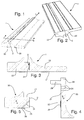
- the insulating member 1 comprise a first portion in the form of a first insulating element 20 and a second portion in the form of a second insulating element 30, which in the shown embodiment are adapted for insulating the top and bottom frame pieces of a roof window.
- top, bottom and side are used to indicate the intended position of different parts in the installed position even though these parts may be located differently during for example storage and transportation or during manufacture of the insulating member 1.
- internal and exitterior are used to indicate that something is intended to face the interior or exterior of the building in which the insulating member and the roof window are installed, respectively, and the terms “inner” and “outer” that something is intended for facing towards or away from the inner opening surrounded by the frame of the window, respectively, in the installed condition.
- the insulating member 1 has an elongate shape with a length in the length direction L corresponding to the length of the frame pieces of the roof window, which it is adapted for insulating, and a pre-defined cross-section which is substantially uniform along the length. While the cross-sections of the two insulating elements 20, 30 shown in this embodiment are different from each other, they can in some embodiments be identical.
- the insulating elements 20, 30 may be made from any natural or synthetic thermally insulating material, preferably with a thermal conductivity of less than 1 W/mK in order to achieve good insulation properties. In a preferred embodiment less than 0.1 W/mK and in a more preferred embodiment it should be lower than 0.040 W/mK. However, it is also preferable that the material be structurally stable, such that it can provide support for flashing members 14 used on the exterior side or similar, while to an extent being compressible and elastic, such that it is easy to handle and install.
- the insulating elements may be produced simultaneously, such that they are interconnected by the material itself, and, particularly if extrusion is used as the manufacturing method, many insulating members may be produced as one continuous profile which can be cut into appropriate lengths afterwards. These manufacturing options are advantageous as they are cost-efficient.
- the first and second insulating elements 20, 30 may be manufactured individually and interconnected by fastening means, such as adhesives, welds, clamps, etc. or by a combination thereof.
- Fig. 3 to 5 show cross-sectional views of an insulating member 1 according to the invention in the interconnected and separated conditions.
- Each insulating element 20, 30 is designed such that it has an abutment side 21, 31 adapted to abut the outer side of a frame piece of the roof window.
- the insulating member 1 is further designed such that the width between the abutment side 21, 31 and the opposing side of the first and second insulating elements 20, 30 decreases along the height h of each insulating element, so that they may follow the shape of the flashing members 14 as will be described with reference to fig. 6-8 . As shown, this decrease does not have to be continuous or over the entire height h of the insulating elements.
- the second insulating element 30 is connected to the first insulating element 20 at a part of its abutment side 31, such that the abutment side 31 is only fully exposed after the separation.
- the first insulating element 20 is connected to the second insulating element 30 at an interior side which is adapted for, in the installed condition, facing the interior direction, such that the abutment side 21 of the first insulating element 20 forms part of the surface of the interconnected insulation member 1.
- the first and second insulating elements 20, 30 can be interconnected at others sides as will be readily understood by the skilled person.
- the insulating member is designed with a weakening of the interconnection at the separation zone 2, which weakening is realized by a slit extending partially through the insulating member 1, such that the insulating member 1 will separate at the material in extension of the slit if pulled or wringed apart.
- Similar structural weakenings may be realized by a gap, a cavity, a row of cavities, etc., or a combination thereof extending through or into the insulating member 1 at the separation zone 2.
- the embodiment of the first and second insulating elements 20, 30 of the insulating member 1 shown in fig. 4 and 5 further comprise secondary separation zones 24, 34 on each insulating element.
- These secondary separation zones 24, 34 provide adaptation options of the cross-sectional shape of each insulating element, such that an insulating element can be adapted according to a secondary building component, the angle at which the roof window is installed, and/or the installation depth of the roof window, by providing the option of tearing or cutting superfluous material away if needed.
- the shown embodiments comprise multiple secondary separation zones 24 on the first insulating element 20 and only one secondary separation zone 34 on the second insulating element 30, the number and positions of the secondary separation zones of each insulating element may vary in other embodiments.
- the first and second insulating elements 20, 30 shown in fig. 3-5 further comprise adhesives 25, 35 arranged on the abutment side 21 of the first insulating element 20 and on the interior side the second insulating element 30, which adhesives are adapted for at least temporarily fastening the insulating elements 20, 30 to the roof structure or a frame piece of the roof window during installation.
- Some embodiments may have several such adhesives arranged on the abutment and/or on other sides.
- each of the adhesives 25, 35 are covered by a cover strip 26, 36 ensuring that the adhesives 25, 35 are protected up until use.
- the first insulating element 20 comprise a sealing element 28, which is projecting out from the first abutment side 21 and which is adapted to provide a sealing between a frame piece of the roof window and an outer cover.
- the sealing element is molded or extruded with the insulating member 1, it can however also be produced separately and attached, in which case it may be produced from a material different from that of the insulating element such as rubber or polymers.
- the second insulating element 30 can also be provided with a similar sealing element.
- the first insulating element further comprise a guide abutment 29 projecting out from the top of the insulating element 20, such that it in an installed condition extends substantially perpendicularly away from the frame of the window in the exterior direction, said guide abutment 29 being adapted to facilitate placement of a cover for the frame of the roof window by providing an abutment which the cover can be pushed against to ensure that it is aligned with the frame of the window.
- the guide abutment 29 is in the shown embodiment molded or extruded in one piece with the insulating member 1 but it can also be manufactured separately, possibly in one integral piece with the sealing element, and attached afterwards.
- the second insulating element 30 can also be manufactured with a similar guide abutment.
- the second insulating element 30 have a ledge 37 extending from the abutment side 31 of the insulating element. It is adapted for extending below the interior side of a frame piece or into an indentation of the frame piece, such that the insulating element supports the frame and fills the space below the part of the window which projects above the roof.
- the first insulating element 20 can also be manufactured with a similar ledge.
- Fig. 6-8 show an insulating member 1 in the installed condition with a roof window structure 10 installed in a roof opening.
- the insulating member 1 has been separated into the first and second insulating elements 20, 30 and used to insulate the top and bottom frame pieces 12, 13 by arranging the insulating elements 20, 30 at their respective frame pieces 12, 13 with the height direction of each insulating element pointing in the exterior direction.
- the cross-sectional shape of the insulating elements 20, 30 allow them to substantially follow the shape of the flashing members 14, thereby allowing the flashing members 14 to withstand external pressure which they might be subjected to, particularly during installation of the roof window, and providing improved insulation.
- Fig. 7 further show how a sealing element 28 on the first insulating element 20 provides a seal between the top frame cover 15 and the exterior side of the top frame piece 12 giving the roof window 10 improved sound and thermal insulating properties.
- the figure also shows that the edge of the cover 15 have been pushed against a guide abutment 29 provided on the first insulating element 20, thereby assuring that the cover 15 is aligned with the frame piece 12.
- the sealing element 28 and guide abutment 29 have been provided by means of a separate element attached to the insulating element during installation.
- Fig. 9-12 show various examples of how the separation zone may be provided.
- the separation zone has been defined by a portion of the insulating member wherein the material density is reduced locally to lower the strength compared to the remaining material.
- the two insulating elements have been connected by using an adhesive.
- the separation zone have been defined by a row of cavities, each cavity extending through the material in the length direction.
- the insulating elements have been connected by means of a secondary material, such as a weaker polymer.
Landscapes
- Engineering & Computer Science (AREA)
- Architecture (AREA)
- Civil Engineering (AREA)
- Structural Engineering (AREA)
- Physics & Mathematics (AREA)
- Electromagnetism (AREA)
- Building Environments (AREA)
Priority Applications (1)
| Application Number | Priority Date | Filing Date | Title |
|---|---|---|---|
| PL16181997T PL3128097T3 (pl) | 2015-08-04 | 2016-07-29 | Sposób izolacji okna dachowego oraz okno dachowe z członem izolacyjnym |
Applications Claiming Priority (1)
| Application Number | Priority Date | Filing Date | Title |
|---|---|---|---|
| DKPA201570502A DK179827B1 (en) | 2015-08-04 | 2015-08-04 | An insulating member, a roof window and a method for insulating a roof window |
Publications (2)
| Publication Number | Publication Date |
|---|---|
| EP3128097A1 true EP3128097A1 (fr) | 2017-02-08 |
| EP3128097B1 EP3128097B1 (fr) | 2021-03-24 |
Family
ID=56555336
Family Applications (1)
| Application Number | Title | Priority Date | Filing Date |
|---|---|---|---|
| EP16181997.4A Active EP3128097B1 (fr) | 2015-08-04 | 2016-07-29 | Procédé d'isolation d'une fenêtre de toit et fenêtre de toit avec élément isolant |
Country Status (5)
| Country | Link |
|---|---|
| EP (1) | EP3128097B1 (fr) |
| DK (1) | DK179827B1 (fr) |
| ES (1) | ES2864755T3 (fr) |
| HU (1) | HUE054414T2 (fr) |
| PL (1) | PL3128097T3 (fr) |
Cited By (4)
| Publication number | Priority date | Publication date | Assignee | Title |
|---|---|---|---|---|
| EP3564460A1 (fr) * | 2018-04-30 | 2019-11-06 | VKR Holding A/S | Fenêtre de toit avec renforcement dans l'élément châssis supérieur |
| EP3859093A1 (fr) * | 2020-02-03 | 2021-08-04 | VKR Holding A/S | Cadre adaptateur pour installer une fenêtre du jour, système comprenant une fenêtre du jour et procédé d'installation d'une et procédés à l'aide d'un cadre adaptateur |
| EP3971363A1 (fr) | 2020-09-22 | 2022-03-23 | VKR Holding A/S | Fenêtre de toit comportant un élément de vitre amélioré et procédé de fabrication d'une fenêtre de toit |
| DE102016114011B4 (de) | 2015-08-04 | 2022-11-17 | Vkr Holding A/S | Verfahren zum Verpacken eines Fensters mit einer Rahmenisolation und ein verpacktes Fenster |
Citations (4)
| Publication number | Priority date | Publication date | Assignee | Title |
|---|---|---|---|---|
| EP1739247A1 (fr) * | 2005-06-30 | 2007-01-03 | VKR Holding A/S | Châssis isolant pour une lucarne |
| EP1760220A1 (fr) * | 2005-09-05 | 2007-03-07 | VKR Holding A/S | Cadre de fenêtre de toit et son procédé de fabrication |
| EP2182132A2 (fr) * | 2008-11-04 | 2010-05-05 | Roto Frank Ag | Fenêtre de toit, en particulier pour une maison |
| EP2466032A1 (fr) * | 2010-12-17 | 2012-06-20 | VKR Holding A/S | Élément isolant avec deux éléments du materiaux différents et procédé pour isoler une fenêtre dans une structure de toit inclinée avec cet élément |
Family Cites Families (2)
| Publication number | Priority date | Publication date | Assignee | Title |
|---|---|---|---|---|
| DE60307869T2 (de) * | 2003-12-30 | 2007-04-12 | Vkr Holding A/S | Fenster |
| HUE042005T2 (hu) * | 2013-08-16 | 2019-06-28 | Keylite Roof Windows Ltd | Tömítõelem |
-
2015
- 2015-08-04 DK DKPA201570502A patent/DK179827B1/en not_active IP Right Cessation
-
2016
- 2016-07-29 ES ES16181997T patent/ES2864755T3/es active Active
- 2016-07-29 PL PL16181997T patent/PL3128097T3/pl unknown
- 2016-07-29 HU HUE16181997A patent/HUE054414T2/hu unknown
- 2016-07-29 EP EP16181997.4A patent/EP3128097B1/fr active Active
Patent Citations (4)
| Publication number | Priority date | Publication date | Assignee | Title |
|---|---|---|---|---|
| EP1739247A1 (fr) * | 2005-06-30 | 2007-01-03 | VKR Holding A/S | Châssis isolant pour une lucarne |
| EP1760220A1 (fr) * | 2005-09-05 | 2007-03-07 | VKR Holding A/S | Cadre de fenêtre de toit et son procédé de fabrication |
| EP2182132A2 (fr) * | 2008-11-04 | 2010-05-05 | Roto Frank Ag | Fenêtre de toit, en particulier pour une maison |
| EP2466032A1 (fr) * | 2010-12-17 | 2012-06-20 | VKR Holding A/S | Élément isolant avec deux éléments du materiaux différents et procédé pour isoler une fenêtre dans une structure de toit inclinée avec cet élément |
Cited By (4)
| Publication number | Priority date | Publication date | Assignee | Title |
|---|---|---|---|---|
| DE102016114011B4 (de) | 2015-08-04 | 2022-11-17 | Vkr Holding A/S | Verfahren zum Verpacken eines Fensters mit einer Rahmenisolation und ein verpacktes Fenster |
| EP3564460A1 (fr) * | 2018-04-30 | 2019-11-06 | VKR Holding A/S | Fenêtre de toit avec renforcement dans l'élément châssis supérieur |
| EP3859093A1 (fr) * | 2020-02-03 | 2021-08-04 | VKR Holding A/S | Cadre adaptateur pour installer une fenêtre du jour, système comprenant une fenêtre du jour et procédé d'installation d'une et procédés à l'aide d'un cadre adaptateur |
| EP3971363A1 (fr) | 2020-09-22 | 2022-03-23 | VKR Holding A/S | Fenêtre de toit comportant un élément de vitre amélioré et procédé de fabrication d'une fenêtre de toit |
Also Published As
| Publication number | Publication date |
|---|---|
| PL3128097T3 (pl) | 2021-09-13 |
| HUE054414T2 (hu) | 2021-09-28 |
| ES2864755T3 (es) | 2021-10-14 |
| DK201570502A1 (en) | 2017-03-06 |
| DK179827B1 (en) | 2019-07-17 |
| EP3128097B1 (fr) | 2021-03-24 |
Similar Documents
| Publication | Publication Date | Title |
|---|---|---|
| EP3128097B1 (fr) | Procédé d'isolation d'une fenêtre de toit et fenêtre de toit avec élément isolant | |
| EP3341540B1 (fr) | Procédé d'assemblage d'un premier et d'un identique deuxième panneau à une structure porteuse | |
| CA3152689C (fr) | Paroi etanche moulee en deux etapes | |
| RU2630944C2 (ru) | Профилированный элемент для соединения стекла транспортного средства с деталью обшивки и узел профилированного элемента | |
| KR20120093245A (ko) | 박벽의 냉간 성형된 경량의 구조 프로파일 요소 및 그러한 프로파일 요소를 생산하는 방법 | |
| JP2018516801A (ja) | 異形帯材、異形帯材を製造するためのシステムおよび方法 | |
| EP3039198B1 (fr) | Élément de raccord destiné à être utilisé dans un ensemble solin pour fenêtres de toit montées côte à côte, et procédé pour monter un ensemble solin | |
| KR102262976B1 (ko) | 건물 외벽의 복합패널 마감구조 | |
| JP3223285U (ja) | フラッシュ部材と屋根材との間で使用されるシール部材、このシール部材を有するフラッシュキット、及び耐候性を付与する方法 | |
| KR20130090178A (ko) | 건축물 옥상 단열 방수 시공 구조 및 방법 | |
| KR101866750B1 (ko) | 건물외장재 고정브라켓 제조방법 및 이에 의해 제조되는 건물외장재 고정브라켓 | |
| KR101920704B1 (ko) | 무근 일체화 키를 갖는 콘크리트 구조물의 테두리 보호장치 | |
| KR20140046832A (ko) | 기밀성을 향상시킨 창호용 단열 스트립바 | |
| KR101950962B1 (ko) | 도로용 가드레일 | |
| KR101791911B1 (ko) | 강성향상형 원형 구조로 이루어진 건축구조물용 알루미늄 샷시 | |
| KR20190017211A (ko) | 변형을 방지하는 이질의 단열재가 부가된 알루미늄 샤시 | |
| EP2546449B1 (fr) | Profilé composite amélioré, profilé pour un tel profilé composite et procédé d'assemblage d'un tel profilé composite | |
| KR101093619B1 (ko) | 단열프레임의 제조방법 및 단열프레임 | |
| JP5701431B1 (ja) | 軒先換気構造体 | |
| CN111434870A (zh) | 包括瞬时变形区域的隔离框架 | |
| CN107208418A (zh) | 梁柱结构 | |
| JP7190125B2 (ja) | 建築材料、及び、施工方法 | |
| KR20170008364A (ko) | 복합창호의 패널 결합구조 | |
| JP4948497B2 (ja) | 縦葺き外装構造 | |
| KR100874255B1 (ko) | 알루미늄 창틀 |
Legal Events
| Date | Code | Title | Description |
|---|---|---|---|
| PUAI | Public reference made under article 153(3) epc to a published international application that has entered the european phase |
Free format text: ORIGINAL CODE: 0009012 |
|
| STAA | Information on the status of an ep patent application or granted ep patent |
Free format text: STATUS: THE APPLICATION HAS BEEN PUBLISHED |
|
| AK | Designated contracting states |
Kind code of ref document: A1 Designated state(s): AL AT BE BG CH CY CZ DE DK EE ES FI FR GB GR HR HU IE IS IT LI LT LU LV MC MK MT NL NO PL PT RO RS SE SI SK SM TR |
|
| AX | Request for extension of the european patent |
Extension state: BA ME |
|
| STAA | Information on the status of an ep patent application or granted ep patent |
Free format text: STATUS: REQUEST FOR EXAMINATION WAS MADE |
|
| 17P | Request for examination filed |
Effective date: 20170609 |
|
| RBV | Designated contracting states (corrected) |
Designated state(s): AL AT BE BG CH CY CZ DE DK EE ES FI FR GB GR HR HU IE IS IT LI LT LU LV MC MK MT NL NO PL PT RO RS SE SI SK SM TR |
|
| STAA | Information on the status of an ep patent application or granted ep patent |
Free format text: STATUS: EXAMINATION IS IN PROGRESS |
|
| 17Q | First examination report despatched |
Effective date: 20170913 |
|
| GRAP | Despatch of communication of intention to grant a patent |
Free format text: ORIGINAL CODE: EPIDOSNIGR1 |
|
| STAA | Information on the status of an ep patent application or granted ep patent |
Free format text: STATUS: GRANT OF PATENT IS INTENDED |
|
| INTG | Intention to grant announced |
Effective date: 20200507 |
|
| GRAJ | Information related to disapproval of communication of intention to grant by the applicant or resumption of examination proceedings by the epo deleted |
Free format text: ORIGINAL CODE: EPIDOSDIGR1 |
|
| STAA | Information on the status of an ep patent application or granted ep patent |
Free format text: STATUS: EXAMINATION IS IN PROGRESS |
|
| GRAP | Despatch of communication of intention to grant a patent |
Free format text: ORIGINAL CODE: EPIDOSNIGR1 |
|
| STAA | Information on the status of an ep patent application or granted ep patent |
Free format text: STATUS: GRANT OF PATENT IS INTENDED |
|
| INTC | Intention to grant announced (deleted) | ||
| INTG | Intention to grant announced |
Effective date: 20201013 |
|
| GRAS | Grant fee paid |
Free format text: ORIGINAL CODE: EPIDOSNIGR3 |
|
| GRAA | (expected) grant |
Free format text: ORIGINAL CODE: 0009210 |
|
| STAA | Information on the status of an ep patent application or granted ep patent |
Free format text: STATUS: THE PATENT HAS BEEN GRANTED |
|
| AK | Designated contracting states |
Kind code of ref document: B1 Designated state(s): AL AT BE BG CH CY CZ DE DK EE ES FI FR GB GR HR HU IE IS IT LI LT LU LV MC MK MT NL NO PL PT RO RS SE SI SK SM TR |
|
| REG | Reference to a national code |
Ref country code: GB Ref legal event code: FG4D |
|
| REG | Reference to a national code |
Ref country code: CH Ref legal event code: EP |
|
| REG | Reference to a national code |
Ref country code: IE Ref legal event code: FG4D |
|
| REG | Reference to a national code |
Ref country code: DE Ref legal event code: R096 Ref document number: 602016054717 Country of ref document: DE Ref country code: AT Ref legal event code: REF Ref document number: 1374653 Country of ref document: AT Kind code of ref document: T Effective date: 20210415 |
|
| REG | Reference to a national code |
Ref country code: NL Ref legal event code: FP |
|
| REG | Reference to a national code |
Ref country code: LT Ref legal event code: MG9D |
|
| PG25 | Lapsed in a contracting state [announced via postgrant information from national office to epo] |
Ref country code: NO Free format text: LAPSE BECAUSE OF FAILURE TO SUBMIT A TRANSLATION OF THE DESCRIPTION OR TO PAY THE FEE WITHIN THE PRESCRIBED TIME-LIMIT Effective date: 20210624 Ref country code: GR Free format text: LAPSE BECAUSE OF FAILURE TO SUBMIT A TRANSLATION OF THE DESCRIPTION OR TO PAY THE FEE WITHIN THE PRESCRIBED TIME-LIMIT Effective date: 20210625 Ref country code: FI Free format text: LAPSE BECAUSE OF FAILURE TO SUBMIT A TRANSLATION OF THE DESCRIPTION OR TO PAY THE FEE WITHIN THE PRESCRIBED TIME-LIMIT Effective date: 20210324 Ref country code: HR Free format text: LAPSE BECAUSE OF FAILURE TO SUBMIT A TRANSLATION OF THE DESCRIPTION OR TO PAY THE FEE WITHIN THE PRESCRIBED TIME-LIMIT Effective date: 20210324 Ref country code: BG Free format text: LAPSE BECAUSE OF FAILURE TO SUBMIT A TRANSLATION OF THE DESCRIPTION OR TO PAY THE FEE WITHIN THE PRESCRIBED TIME-LIMIT Effective date: 20210624 |
|
| PG25 | Lapsed in a contracting state [announced via postgrant information from national office to epo] |
Ref country code: RS Free format text: LAPSE BECAUSE OF FAILURE TO SUBMIT A TRANSLATION OF THE DESCRIPTION OR TO PAY THE FEE WITHIN THE PRESCRIBED TIME-LIMIT Effective date: 20210324 Ref country code: LV Free format text: LAPSE BECAUSE OF FAILURE TO SUBMIT A TRANSLATION OF THE DESCRIPTION OR TO PAY THE FEE WITHIN THE PRESCRIBED TIME-LIMIT Effective date: 20210324 Ref country code: SE Free format text: LAPSE BECAUSE OF FAILURE TO SUBMIT A TRANSLATION OF THE DESCRIPTION OR TO PAY THE FEE WITHIN THE PRESCRIBED TIME-LIMIT Effective date: 20210324 |
|
| REG | Reference to a national code |
Ref country code: HU Ref legal event code: AG4A Ref document number: E054414 Country of ref document: HU |
|
| REG | Reference to a national code |
Ref country code: ES Ref legal event code: FG2A Ref document number: 2864755 Country of ref document: ES Kind code of ref document: T3 Effective date: 20211014 |
|
| PG25 | Lapsed in a contracting state [announced via postgrant information from national office to epo] |
Ref country code: SM Free format text: LAPSE BECAUSE OF FAILURE TO SUBMIT A TRANSLATION OF THE DESCRIPTION OR TO PAY THE FEE WITHIN THE PRESCRIBED TIME-LIMIT Effective date: 20210324 Ref country code: EE Free format text: LAPSE BECAUSE OF FAILURE TO SUBMIT A TRANSLATION OF THE DESCRIPTION OR TO PAY THE FEE WITHIN THE PRESCRIBED TIME-LIMIT Effective date: 20210324 Ref country code: LT Free format text: LAPSE BECAUSE OF FAILURE TO SUBMIT A TRANSLATION OF THE DESCRIPTION OR TO PAY THE FEE WITHIN THE PRESCRIBED TIME-LIMIT Effective date: 20210324 |
|
| PG25 | Lapsed in a contracting state [announced via postgrant information from national office to epo] |
Ref country code: PT Free format text: LAPSE BECAUSE OF FAILURE TO SUBMIT A TRANSLATION OF THE DESCRIPTION OR TO PAY THE FEE WITHIN THE PRESCRIBED TIME-LIMIT Effective date: 20210726 Ref country code: SK Free format text: LAPSE BECAUSE OF FAILURE TO SUBMIT A TRANSLATION OF THE DESCRIPTION OR TO PAY THE FEE WITHIN THE PRESCRIBED TIME-LIMIT Effective date: 20210324 Ref country code: RO Free format text: LAPSE BECAUSE OF FAILURE TO SUBMIT A TRANSLATION OF THE DESCRIPTION OR TO PAY THE FEE WITHIN THE PRESCRIBED TIME-LIMIT Effective date: 20210324 Ref country code: IS Free format text: LAPSE BECAUSE OF FAILURE TO SUBMIT A TRANSLATION OF THE DESCRIPTION OR TO PAY THE FEE WITHIN THE PRESCRIBED TIME-LIMIT Effective date: 20210724 |
|
| REG | Reference to a national code |
Ref country code: DE Ref legal event code: R097 Ref document number: 602016054717 Country of ref document: DE |
|
| PG25 | Lapsed in a contracting state [announced via postgrant information from national office to epo] |
Ref country code: AL Free format text: LAPSE BECAUSE OF FAILURE TO SUBMIT A TRANSLATION OF THE DESCRIPTION OR TO PAY THE FEE WITHIN THE PRESCRIBED TIME-LIMIT Effective date: 20210324 Ref country code: DK Free format text: LAPSE BECAUSE OF FAILURE TO SUBMIT A TRANSLATION OF THE DESCRIPTION OR TO PAY THE FEE WITHIN THE PRESCRIBED TIME-LIMIT Effective date: 20210324 |
|
| PLBE | No opposition filed within time limit |
Free format text: ORIGINAL CODE: 0009261 |
|
| STAA | Information on the status of an ep patent application or granted ep patent |
Free format text: STATUS: NO OPPOSITION FILED WITHIN TIME LIMIT |
|
| PG25 | Lapsed in a contracting state [announced via postgrant information from national office to epo] |
Ref country code: SI Free format text: LAPSE BECAUSE OF FAILURE TO SUBMIT A TRANSLATION OF THE DESCRIPTION OR TO PAY THE FEE WITHIN THE PRESCRIBED TIME-LIMIT Effective date: 20210324 |
|
| 26N | No opposition filed |
Effective date: 20220104 |
|
| PG25 | Lapsed in a contracting state [announced via postgrant information from national office to epo] |
Ref country code: MC Free format text: LAPSE BECAUSE OF FAILURE TO SUBMIT A TRANSLATION OF THE DESCRIPTION OR TO PAY THE FEE WITHIN THE PRESCRIBED TIME-LIMIT Effective date: 20210324 |
|
| PG25 | Lapsed in a contracting state [announced via postgrant information from national office to epo] |
Ref country code: IS Free format text: LAPSE BECAUSE OF FAILURE TO SUBMIT A TRANSLATION OF THE DESCRIPTION OR TO PAY THE FEE WITHIN THE PRESCRIBED TIME-LIMIT Effective date: 20210724 Ref country code: LU Free format text: LAPSE BECAUSE OF NON-PAYMENT OF DUE FEES Effective date: 20210729 |
|
| PG25 | Lapsed in a contracting state [announced via postgrant information from national office to epo] |
Ref country code: IE Free format text: LAPSE BECAUSE OF NON-PAYMENT OF DUE FEES Effective date: 20210729 |
|
| REG | Reference to a national code |
Ref country code: AT Ref legal event code: UEP Ref document number: 1374653 Country of ref document: AT Kind code of ref document: T Effective date: 20210324 |
|
| PG25 | Lapsed in a contracting state [announced via postgrant information from national office to epo] |
Ref country code: CY Free format text: LAPSE BECAUSE OF FAILURE TO SUBMIT A TRANSLATION OF THE DESCRIPTION OR TO PAY THE FEE WITHIN THE PRESCRIBED TIME-LIMIT Effective date: 20210324 |
|
| PGFP | Annual fee paid to national office [announced via postgrant information from national office to epo] |
Ref country code: NL Payment date: 20230614 Year of fee payment: 8 Ref country code: IT Payment date: 20230612 Year of fee payment: 8 Ref country code: FR Payment date: 20230622 Year of fee payment: 8 Ref country code: CZ Payment date: 20230629 Year of fee payment: 8 |
|
| PGFP | Annual fee paid to national office [announced via postgrant information from national office to epo] |
Ref country code: BE Payment date: 20230616 Year of fee payment: 8 |
|
| PGFP | Annual fee paid to national office [announced via postgrant information from national office to epo] |
Ref country code: GB Payment date: 20230608 Year of fee payment: 8 Ref country code: ES Payment date: 20230808 Year of fee payment: 8 Ref country code: CH Payment date: 20230801 Year of fee payment: 8 Ref country code: AT Payment date: 20230626 Year of fee payment: 8 |
|
| PGFP | Annual fee paid to national office [announced via postgrant information from national office to epo] |
Ref country code: HU Payment date: 20230626 Year of fee payment: 8 |
|
| PG25 | Lapsed in a contracting state [announced via postgrant information from national office to epo] |
Ref country code: MK Free format text: LAPSE BECAUSE OF FAILURE TO SUBMIT A TRANSLATION OF THE DESCRIPTION OR TO PAY THE FEE WITHIN THE PRESCRIBED TIME-LIMIT Effective date: 20210324 |
|
| PG25 | Lapsed in a contracting state [announced via postgrant information from national office to epo] |
Ref country code: TR Free format text: LAPSE BECAUSE OF FAILURE TO SUBMIT A TRANSLATION OF THE DESCRIPTION OR TO PAY THE FEE WITHIN THE PRESCRIBED TIME-LIMIT Effective date: 20210324 |
|
| PG25 | Lapsed in a contracting state [announced via postgrant information from national office to epo] |
Ref country code: MT Free format text: LAPSE BECAUSE OF FAILURE TO SUBMIT A TRANSLATION OF THE DESCRIPTION OR TO PAY THE FEE WITHIN THE PRESCRIBED TIME-LIMIT Effective date: 20210324 |
|
| REG | Reference to a national code |
Ref country code: CH Ref legal event code: PL |
|
| REG | Reference to a national code |
Ref country code: NL Ref legal event code: MM Effective date: 20240801 |
|
| REG | Reference to a national code |
Ref country code: AT Ref legal event code: MM01 Ref document number: 1374653 Country of ref document: AT Kind code of ref document: T Effective date: 20240729 |
|
| GBPC | Gb: european patent ceased through non-payment of renewal fee |
Effective date: 20240729 |
|
| PG25 | Lapsed in a contracting state [announced via postgrant information from national office to epo] |
Ref country code: HU Free format text: LAPSE BECAUSE OF NON-PAYMENT OF DUE FEES Effective date: 20240730 |
|
| PG25 | Lapsed in a contracting state [announced via postgrant information from national office to epo] |
Ref country code: HU Free format text: LAPSE BECAUSE OF NON-PAYMENT OF DUE FEES Effective date: 20240730 |
|
| PG25 | Lapsed in a contracting state [announced via postgrant information from national office to epo] |
Ref country code: NL Free format text: LAPSE BECAUSE OF NON-PAYMENT OF DUE FEES Effective date: 20240801 |
|
| PG25 | Lapsed in a contracting state [announced via postgrant information from national office to epo] |
Ref country code: CH Free format text: LAPSE BECAUSE OF NON-PAYMENT OF DUE FEES Effective date: 20240731 Ref country code: AT Free format text: LAPSE BECAUSE OF NON-PAYMENT OF DUE FEES Effective date: 20240729 Ref country code: BE Free format text: LAPSE BECAUSE OF NON-PAYMENT OF DUE FEES Effective date: 20240731 |
|
| PG25 | Lapsed in a contracting state [announced via postgrant information from national office to epo] |
Ref country code: CZ Free format text: LAPSE BECAUSE OF NON-PAYMENT OF DUE FEES Effective date: 20240729 Ref country code: FR Free format text: LAPSE BECAUSE OF NON-PAYMENT OF DUE FEES Effective date: 20240731 |
|
| PG25 | Lapsed in a contracting state [announced via postgrant information from national office to epo] |
Ref country code: GB Free format text: LAPSE BECAUSE OF NON-PAYMENT OF DUE FEES Effective date: 20240729 |
|
| REG | Reference to a national code |
Ref country code: BE Ref legal event code: MM Effective date: 20240731 |
|
| PGFP | Annual fee paid to national office [announced via postgrant information from national office to epo] |
Ref country code: PL Payment date: 20250612 Year of fee payment: 10 |
|
| PG25 | Lapsed in a contracting state [announced via postgrant information from national office to epo] |
Ref country code: IT Free format text: LAPSE BECAUSE OF NON-PAYMENT OF DUE FEES Effective date: 20240729 |
|
| REG | Reference to a national code |
Ref country code: ES Ref legal event code: FD2A Effective date: 20250905 |
|
| PG25 | Lapsed in a contracting state [announced via postgrant information from national office to epo] |
Ref country code: ES Free format text: LAPSE BECAUSE OF NON-PAYMENT OF DUE FEES Effective date: 20240730 |
|
| PGFP | Annual fee paid to national office [announced via postgrant information from national office to epo] |
Ref country code: DE Payment date: 20250604 Year of fee payment: 10 |