EP3128121B1 - Cadre d'abandon de puits, cartouche et procédé de mise en oeuvre des opérations d'abandon - Google Patents
Cadre d'abandon de puits, cartouche et procédé de mise en oeuvre des opérations d'abandon Download PDFInfo
- Publication number
- EP3128121B1 EP3128121B1 EP16181312.6A EP16181312A EP3128121B1 EP 3128121 B1 EP3128121 B1 EP 3128121B1 EP 16181312 A EP16181312 A EP 16181312A EP 3128121 B1 EP3128121 B1 EP 3128121B1
- Authority
- EP
- European Patent Office
- Prior art keywords
- frame
- abandonment
- cartridge
- well
- ring
- Prior art date
- Legal status (The legal status is an assumption and is not a legal conclusion. Google has not performed a legal analysis and makes no representation as to the accuracy of the status listed.)
- Active
Links
Images











Classifications
-
- E—FIXED CONSTRUCTIONS
- E21—EARTH OR ROCK DRILLING; MINING
- E21B—EARTH OR ROCK DRILLING; OBTAINING OIL, GAS, WATER, SOLUBLE OR MELTABLE MATERIALS OR A SLURRY OF MINERALS FROM WELLS
- E21B33/00—Sealing or packing boreholes or wells
- E21B33/02—Surface sealing or packing
- E21B33/03—Well heads; Setting-up thereof
- E21B33/035—Well heads; Setting-up thereof specially adapted for underwater installations
- E21B33/037—Protective housings therefor
-
- E—FIXED CONSTRUCTIONS
- E21—EARTH OR ROCK DRILLING; MINING
- E21B—EARTH OR ROCK DRILLING; OBTAINING OIL, GAS, WATER, SOLUBLE OR MELTABLE MATERIALS OR A SLURRY OF MINERALS FROM WELLS
- E21B41/00—Equipment or details not covered by groups E21B15/00 - E21B40/00
- E21B41/08—Underwater guide bases, e.g. drilling templates; Levelling thereof
-
- E—FIXED CONSTRUCTIONS
- E21—EARTH OR ROCK DRILLING; MINING
- E21B—EARTH OR ROCK DRILLING; OBTAINING OIL, GAS, WATER, SOLUBLE OR MELTABLE MATERIALS OR A SLURRY OF MINERALS FROM WELLS
- E21B19/00—Handling rods, casings, tubes or the like outside the borehole, e.g. in the derrick; Apparatus for feeding the rods or cables
-
- E—FIXED CONSTRUCTIONS
- E21—EARTH OR ROCK DRILLING; MINING
- E21B—EARTH OR ROCK DRILLING; OBTAINING OIL, GAS, WATER, SOLUBLE OR MELTABLE MATERIALS OR A SLURRY OF MINERALS FROM WELLS
- E21B33/00—Sealing or packing boreholes or wells
-
- E—FIXED CONSTRUCTIONS
- E21—EARTH OR ROCK DRILLING; MINING
- E21B—EARTH OR ROCK DRILLING; OBTAINING OIL, GAS, WATER, SOLUBLE OR MELTABLE MATERIALS OR A SLURRY OF MINERALS FROM WELLS
- E21B41/00—Equipment or details not covered by groups E21B15/00 - E21B40/00
- E21B41/0007—Equipment or details not covered by groups E21B15/00 - E21B40/00 for underwater installations
- E21B41/0014—Underwater well locating or reentry systems
-
- E—FIXED CONSTRUCTIONS
- E21—EARTH OR ROCK DRILLING; MINING
- E21B—EARTH OR ROCK DRILLING; OBTAINING OIL, GAS, WATER, SOLUBLE OR MELTABLE MATERIALS OR A SLURRY OF MINERALS FROM WELLS
- E21B41/00—Equipment or details not covered by groups E21B15/00 - E21B40/00
- E21B41/06—Work chambers for underwater operations, e.g. temporarily connected to well heads
-
- E—FIXED CONSTRUCTIONS
- E21—EARTH OR ROCK DRILLING; MINING
- E21B—EARTH OR ROCK DRILLING; OBTAINING OIL, GAS, WATER, SOLUBLE OR MELTABLE MATERIALS OR A SLURRY OF MINERALS FROM WELLS
- E21B41/00—Equipment or details not covered by groups E21B15/00 - E21B40/00
- E21B41/10—Guide posts, e.g. releasable; Attaching guide lines to underwater guide bases
-
- E—FIXED CONSTRUCTIONS
- E21—EARTH OR ROCK DRILLING; MINING
- E21B—EARTH OR ROCK DRILLING; OBTAINING OIL, GAS, WATER, SOLUBLE OR MELTABLE MATERIALS OR A SLURRY OF MINERALS FROM WELLS
- E21B7/00—Special methods or apparatus for drilling
- E21B7/12—Underwater drilling
- E21B7/124—Underwater drilling with underwater tool drive prime mover, e.g. portable drilling rigs for use on underwater floors
Definitions
- the invention relates to well abandonment frames for fitting over a well head to facilitate one or more abandonment operations, cartridges for securing to a well abandonment frame and methods of carrying out abandonment operations on a well head.
- the structures which are envisaged in certain embodiments of the invention may be specifically designed to restrict and/or control the loads imparted both during installation of the structure and subsequently into the particularly load-sensitive wells.
- load-sensitive wells are susceptible to both structural overload if a large axial or bending load is applied and also to a fatigue failure if cyclic loads are applied.
- the cyclic loads can be of a much smaller magnitude than those which are capable of causing structural overload.
- the invention provides a well abandonment frame for fitting over a well head to facilitate one or more abandonment operations comprising a plurality of upwardly extending load bearing legs and a plurality of junction members joining said legs to form said frame; said junction members presenting an aperture through which said abandonment operations are carried out; said aperture being defined by a rim for engagement with one or a succession of cartridges which are secured to facilitate one or a plurality of abandonment operations.
- This configuration is particularly advantageous because it allows the aperture in certain embodiments to potentially entirely clear and thus avoid contact with the well head which is destined for abandonment and ultimately removal. It is also particularly advantageous because it allows a plurality of load inducing devices to be fitted to the structure for the completion of a plurality of well head abandonment operations.
- the rim is circular. This provides the optimum configuration for the centralisation of the cartridges onto the frame.
- the frame incorporates a plurality of concentric rims. These provide an optimum level of structural strength whilst allowing the tree of the well head to be cleared and positioned centrally relative to the frame itself.
- the frame incorporates not only a plurality of concentric rims but these are arranged so that a lower rim, an intermediate rim and an upper rim are provided where the intermediate rim has a diameter which is lower than both the diameter of the upper and lower rims.
- This configuration is particularly advantageous because it provides the succession of rims or rings with a so-called hourglass configuration which allows optimum placement of the frame onto and around the well head structure.
- the lower rim's diameter allows sufficient clearance to cope with the almost unavoidable effect of currents and waves on the lowering process of the frame onto the seabed.
- the intermediate rim allows optimum centralisation of the frame relative to the well head which is destined for abandonment which facilitates optimum completion of the abandonment operations.
- the upper rim is also particularly advantageous since it facilitates the interface between a cartridge for the execution of abandonment operations.
- the legs incorporate means for adjusting the length of the legs. This configuration is particularly advantageous in order to allow the frame to cope with unevenness in the relief of the seabed surrounding the well in need of abandonment.
- the legs incorporate a mud mat and means for vertically displacing the mud mat. This configuration is particularly advantageous in order to allow the load carried by the legs to be spread over a large surface area of the seabed.
- one or more of the legs incorporates a longitudinal tunnel and accommodates a pile which may be driven into the bed on which the frame is mounted. This allows the frame to be secured to the seabed not only via the legs themselves but optionally with the extra security provided by a plurality of piles which may be driven into the seabed.
- the upper aperture of the longitudinal tunnel incorporates a funnel. This allows advantageously the piles to be more readily centralised into the tunnel of the legs for more straightforward assembly.
- the legs incorporate a plurality of locks for locking the legs onto the pile.
- This configuration further reinforces the structural strength and stability of the frame when secured to the seabed. In addition, it prevents upward movement of the frame relative to the pile.
- the invention provides a cartridge for securing to a well abandonment frame according to any of the preceding aspects
- the cartridge comprises in this further aspect a rim for securing to the upper rim of a frame according to a preceding aspect and a plurality of downwardly extending guide rods for centralising the rim onto the upper rim.
- This configuration is particularly advantageous in terms of achieving an optimum interface between a cartridge and the well abandonment frame. It also provides a mechanism for centralising the engagement of the respective rims or rings.
- the rim incorporates a plurality of dampers for engaging the upper rim.
- This configuration is particularly advantageous for controlling the engagement of the respective rims of the cartridge and of the frame. This configuration will avoid or significantly minimise any mechanical impact or vibration which could affect the success of the abandonment operations.
- the dampers are adjustable in height by remote control. This configuration is particularly advantageous in order to control the lowering of the dampers in order to achieve a particularly advantageously stable engagement of the cartridge and the frame.
- the cartridge further comprises a locking mechanism. This allows advantageously the respective rims to be engaged in an interfacing manner in an advantageously secure manner.
- the cartridge further comprises an arm for locking the cartridge onto the upper rim.
- This configuration is particularly advantageous in terms of the tensile load that may be carried by the arm whilst achieving advantageous immobilisation of one rim relative to the other for successful and potentially successive abandonment operations.
- the cartridge further comprises a locking jaw which clamps onto the upper rim.
- the cartridge further comprises means for carrying out a workover operation.
- the cartridge further comprises a well head extension.
- the invention provides a well abandonment system which comprises a frame according to the preceding aspects and a cartridge according to certain preceding aspects relating to cartridges.
- the system handles a well head which has guide posts whilst the system further comprises a guide frame for securing to the well head's guide posts.
- This configuration is particularly advantageous in terms of further minimising potential contact with the weakest areas of the well head in need of abandonment.
- the invention provides a method of carrying out abandonment operations on a well head comprising the steps of providing a frame according to any of the preceding aspects, positioning the frame about the well head, and carrying out one or more operations by employing one or a succession of cartridges according to any appropriate previously mentioned aspects.
- the well head incorporates guide posts and the method further comprises the step of securing a guide frame to the guide posts. This method is particularly advantageous because it facilitates an initial attachment to parts of the well head which are less susceptible to failure.
- the frame incorporates mud mats and the method further comprises the step of remotely controlling the position of the mud mats. This allows the frame to appropriately distribute the loads onto a potentially uneven seabed.
- the method further comprises the steps of locking one or a succession of the cartridges to the frame. This is particularly advantageous in terms of optimising the distribution of load onto the frame in order to avoid and minimise any load carrying of the well head itself.
- a number of existing well head protective structures may be removed via a combination of divers and remote operated vehicles (so called ROVs).
- Protective structures may for example take the form of a framework which is sufficiently remote from the well head itself in order not to constitute a load risk. Any such framework should be so designed that no or minimal load is applied to the well head during installation of the framework or subsequently. Additionally a framework is able to cope with installation tolerances and can support different pieces of equipment utilised during the abandonment procedure.
- Well head 1 comprises a well head tree 2 from which four guide posts such as guide post 3 extend.
- the guide posts 3 are configured to withstand a certain degree of load compared to the central portion 4 of the well head which is relatively weak and susceptible to failure in well heads which have been abandoned for over thirty years.
- the well head extends from a seabed 5 and is surrounded by pipes such as pipe 6. These pipes may be abandoned conductors or other forms of pipe work.
- Figure 2 shows a vessel 7 with a crane or articulated arm 8 for lowering on its cable 9 a guide frame 10.
- An ROV or a combination of divers may be deployed to assist in the positioning of the guide frame onto the various guide posts of the well head.
- FIG. 3 shows in further detail the components of the guide frame 10.
- the guide frame 10 as described in this Figure ensures that the abandonment frame (see below) runs concentric to the well and that any installation load is not applied to the well head tree directly.
- Guide frame 10 comprises a ring 12 defining the outermost periphery of the guide frame.
- a rectangular frame work 13 links together a number of sleeves such as sleeve 14.
- Sleeves 14 incorporate at their lower extremity a funnel shaped portion 15 which facilities the engagement of the sleeve 14 onto a corresponding guide post 3.
- the rectangular framework 13 is joined to the rim or ring 12 via radially extending struts such as strut 16.
- one of the sleeves 14 incorporates an extension rod 17 extending upwards from the sleeve 14.
- Other embodiments do not necessarily comprise extension rod 17.
- Figure 4 shows guide frame 10 fully engaged on the guide posts 3 of the well head. Identical numerical references have been used in Figure 4 for clarity.
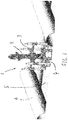
- FIG. 5 describes in detail the positioning of the well abandonment frame generally referenced 18 over the combined well head 1 and its corresponding guide frame 10.
- frame 18 comprises a plurality of upwardly extending legs such as leg 19.
- the configuration of the frame which is designed to minimise or eliminate load passed to the well, is in the present embodiment a generally rectangular form with a leg at each corner of the rectangle. Other configurations may be envisaged dependent upon the layout of the obstacles on the corresponding seabed where the frame is to be deployed.
- Each leg incorporates an upper funnel 20 for facilitating the insertion of an appropriately sized pile (not shown in the figure).
- Each leg may comprise a tunnel extending the length of the leg in order to accommodate the pile.
- a plurality of locks 21 are provided preferably at an upper portion of the leg.
- the locking mechanism may be a hydraulic locking mechanism which may be advantageously remotely controlled.
- the locking mechanism may be a mechanical mechanism which may be either remotely controlled or activated directly by an operator using a remotely operated vehicle or requiring the services of a diver.
- a mud mat 22 is provided for each one of the legs.
- the mud mat may incorporate a central aperture 23 for the insertion of the leg and to facilitate the relative displacement of the mud mat.
- the mud mat may be driven or displaced by one or more rams or hydraulic actuators 24.
- rams or hydraulic actuators 24 In the embodiment shown there are two diametrically oppositely located hydraulic rams 24 and 25.
- the lower extremity of the hydraulic ram may be joined to the mud mat 22 via a triangular mount 26 and a transverse bar 27 extending the length of the rectangular mud mat.
- a pivot point may be provided between the triangular mount 26 and the extremity of the hydraulic ram 24.
- each one of the legs is configured in this form and may be remotely controlled for optimum positioning and levelling relative to the seabed and the wellhead on which an abandonment operation is to be carried out.
- a framework of transverse and vertical struts is provided with a primary function to support an arrangement of several preferably concentric, rings, in particular rings 28, 29 and 30.
- the rings 28-30 enable the frame to cope better with any installation tolerances.
- An upper set of supporting struts is formed first of all by cross-beams such as beam 31 which extend between the legs of the frame. Thereafter, a number of diagonal beams such as beam 32 extend from the respective legs towards the upper ring 28. At the middle section of the cross-beams 31 further struts extend from the cross-beam to the ring such as beam 33. At that junction beams also extend between the upper cross-beam 31 and a lower cross-beam 34 in the form of vertically extending beam 35. Further beams extend in substantially the downwards direction between the various rings 28, 29 and 30 in order to form overall the impression of an hourglass formation. These are for example referenced 36, 37 and 38.
- the relative size of the guide frame 10 and the respective rings 30 and 29 allow for the positioning of the guide frame within the rings in a substantially concentric manner whilst allowing a degree of movement of the frame as it is lowered onto the seabed without causing damage to the well head itself.
- the frame may be positioned with accuracy and concentrically relative to the well head tree.
- the mud mats may be lowered and the piles when necessary may be driven through the tunnels provided in each one of the corresponding legs.
- the hydraulic jacks may be extended in order to achieve the desired level for each one of the legs.
- Figure 9 shows the piles driven into the seabed at a greater depth than in Figure 8 .
- the depth to which the piles are driven into the seabed will depend upon the nature of the seabed and the specific requirements for the frame itself.
- the provision of the piles and the facility to lock the frame to the piles allows loads imparted onto the frame, such as environmental loads or from abandonment equipment, including risers, to be transmitted through the frame, and then via the piles into the soil: so avoiding load transmissions to the well.
- the first stage blow out prevention (BOP) support crown section may be installed.
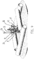
- This support crown section may take the form of a first cartridge 39 as shown in Figure 11 .
- the first stage cartridge 39 is configured to interface with ring 28 of the support frame.
- Cartridge 39 may be lowered down onto the abandonment frame via appropriate cabling and with the controlled use of remotely operated vehicles (ROVs).
- Cartridge 39 has a primary interfacing ring 40 with a plurality of jacks 41 which are configured to dampen substantially in the vertical direction. These act as remotely controlled dampers in preferred embodiments.
- the jacks are configured to allow a four-way dampening effect to minimise any load transfer during installation of the cartridge.
- the dampers and the jacks provide an installation tolerance.
- the cartridge incorporates a number of downwardly extending guide rods such as guide rod 42 which incorporate a tapered lower surface to facilitate the centralisation of the cartridge as these will first come into contact with ring 28 of the frame.
- guide rod 42 which incorporate a tapered lower surface to facilitate the centralisation of the cartridge as these will first come into contact with ring 28 of the frame.
- ring 40 there is provided a boxlike section 43 within which workover equipment is carried.
- a number of bowed shaped portions 44 extend across the upper portion of the boxlike section.
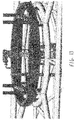
- FIG. 12 shows in greater detail how the cartridge is guided into contact with the upper ring 28.
- the vertically extending rods such as rods 42 are joined together by linkages such as linkage 45.
- Workover equipment 46 incorporates two downwardly extending members 47 and 48 which may engage corresponding portions of the well head tree 49 and 50.
- Figure 13 shows the interconnection of the cartridge with the frame in greater detail. Numerical references have been deliberately omitted for clarity.
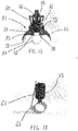
- FIG 14 shows a first locking mechanism generally referenced 51.
- the locking mechanism is attached to the cartridge 39 and is designed to secure onto the ring 28.
- the locking mechanism 51 incorporates two jaws 52 and 53 which incorporate a pivot point such as pivot point 54 the front lower portion of jaw 52 has a radius 55 corresponding substantially to half of the circumference of ring 28.
- a slider 56 is provided and attached to the cartridge 39 which is displaceable in the vertical direction provided sufficient pressure is applied on lower legs 57 and 58.
- the upper portion 59 joins linkage arms 60 and 61 which act eccentrically relative to the pivot point 54 in order to cause the jaws to close when these are lifted due to the pressure applied on the lower portions 57 and 58 thereby clamping the cartridge onto the ring.
- FIG 15 An alternative form of locking mechanism is presented in figure 15 where the cartridge 39 is shown in a region corresponding to the damper and where an arm 62 extends between a portion of the cartridge and a pivot point 63 located in a lateral protrusion preferably to one side of the ring 28.
- Appropriate mechanical fixing means may be provided in order to prevent the vertical displacement of the cartridge relative to the frame.
- a workover section of known kind may be deployed on the upper portion of the cartridge.
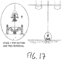
- the well may now be plugged and the tree of the blowout prevention cartridge may be retrieved as the tree may be safely disconnected from the well head.
- the first cartridge may be retrieved along with the now loose tree as shown in Figure 17 . This first stage leaves the well head exposed in preparation for the second stage blowout prevention operation which employs a further kind of cartridge as shown in Figures 19 to 25 .
- FIG 19 shows the installation process for the second cartridge 65.
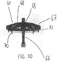
- Cartridge 65 as shown in Figure 20 incorporates a well head extension connector 66 secured onto the central axis of the cartridge's ring 67.
- a number of radially extending junction members 68 are provided towards a central support 69.
- cartridge ring 67 relies on a number of vertically extending guide rods 70 whose lower extremity are at an angle in order to locate and centralise on the frame.
- the cartridge employs a plurality of jacks or dampers 71 which as before allow the engagement of the interfacing rings to be controlled if necessary through remote control means in order to manage the loading of the frame with caution.
- the second cartridge will also envisage their deployment in order to lock the interfacing rings together for the duration of the operation.
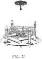
- stage two operations may be carried out.
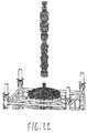
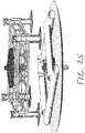
- a five stack subsea blowout prevention device may be landed off onto the second cartridge as shown in Figure 22 and thereafter facilitate well abandonment operations which may be completed from a rig.
- the well head may be cut beneath the surface and retrieved as a complete assembly leaving the seabed entirely clear as shown in Figure 27 .
- the frame and the second cartridge may be removed together in order to simplify the removal process. Any remaining debris and pipework that may have been disposed in the vicinity of the well head may also now be removed in order to achieve an entirely clear seabed.
Landscapes
- Engineering & Computer Science (AREA)
- Life Sciences & Earth Sciences (AREA)
- Geology (AREA)
- Mining & Mineral Resources (AREA)
- Physics & Mathematics (AREA)
- Environmental & Geological Engineering (AREA)
- Fluid Mechanics (AREA)
- General Life Sciences & Earth Sciences (AREA)
- Geochemistry & Mineralogy (AREA)
- Mechanical Engineering (AREA)
- Earth Drilling (AREA)
Claims (17)
- Un cadre d'abandon de puits (18) destiné à s'adapter sur une tête de puits pour faciliter une ou plusieurs opérations d'abandon comprenant une pluralité de pattes de support de charge s'étendant vers le haut (19) et une pluralité d'éléments de jonction reliant lesdites pattes pour former ledit cadre ; lesdits éléments de jonction présentant une ouverture à travers laquelle lesdites opérations d'abandon sont réalisées ; ladite ouverture étant définie par un anneau (28) pour une mise en prise avec une cartouche ou une série de cartouches qui sont assujetties afin de faciliter une opération d'abandon ou une pluralité d'opérations d'abandon.
- Un cadre d'abandon de puits selon la revendication 1, dans lequel ledit anneau (28) est circulaire.
- Un cadre d'abandon de puits selon n'importe laquelle de la revendication 1 ou de la revendication 2, ledit cadre incorporant une pluralité d'anneaux concentriques, et ladite pluralité d'anneaux concentriques incorporant préférablement un anneau inférieur, un anneau intermédiaire et un anneau supérieur ; l'anneau intermédiaire ayant un diamètre qui est inférieur au diamètre à la fois des anneaux supérieur et inférieur.
- Un cadre d'abandon de puits selon n'importe lesquelles des revendications précédentes, dans lequel lesdites pattes incorporent des moyens pour régler la longueur desdites pattes, et lesdites pattes incorporant préférablement un tapis de boue et des moyens pour déplacer verticalement ledit tapis de boue.
- Un cadre d'abandon de puits selon n'importe lesquelles des revendications précédentes, dans lequel une ou plusieurs desdites pattes incorporent un tunnel longitudinal et accueillent une pile qui peut être enfoncée dans le lit sur lequel le cadre est monté, et dans lequel l'ouverture supérieure dudit tunnel longitudinal incorpore préférablement un entonnoir, et plus préférablement encore dans lequel lesdites pattes incorporent une pluralité de verrous pour verrouiller ladite patte sur ladite pile.
- Une cartouche destinée à être assujettie à un cadre d'abandon de puits selon n'importe lesquelles des revendications 1 à 5, comprenant un anneau destiné à être assujetti à l'anneau supérieur d'un cadre selon la revendication 3, et une pluralité de tiges de guidage s'étendant vers le bas pour centrer ledit anneau sur ledit anneau supérieur.
- Une cartouche selon la revendication 6, dans laquelle ladite couronne incorpore une pluralité d'amortisseurs destinés à se mettre en prise avec ledit anneau supérieur, et lesdits amortisseurs étant préférablement réglables en hauteur par commande à distance.
- Une cartouche selon n'importe laquelle de la revendication 6 ou de la revendication 7, comprenant en outre un mécanisme de verrouillage.
- Une cartouche selon n'importe lesquelles de la revendication 6 à la revendication 8, comprenant en outre un bras destiné à verrouiller ladite cartouche sur ledit anneau supérieur.
- Une cartouche selon n'importe lesquelles de la revendication 6 à la revendication 9, comprenant en outre une mâchoire de verrouillage qui se serre sur ledit anneau supérieur.
- Une cartouche selon n'importe lesquelles de la revendication 6 à la revendication 10, comprenant en outre des moyens pour réaliser une opération de reconditionnement.
- Une cartouche selon n'importe lesquelles de la revendication 6 à la revendication 11, comprenant en outre une extension de tête de puits.
- Un système d'abandon de puits comprenant un cadre selon n'importe lesquelles des revendications 1 à 5 et une cartouche selon n'importe lesquelles des revendications 6 à 12.
- Un système selon la revendication 13, dans lequel ladite tête de puits incorpore des montants de guidage et ledit système comprend en outre un cadre de guidage destiné à être assujetti aux montants de guidage de la tête de puits.
- Un procédé de réalisation d'opérations d'abandon sur une tête de puits comprenant les étapes consistant à fournir un cadre selon n'importe lesquelles des revendications 1 à 5, à positionner ledit cadre autour de ladite tête de puits, et à réaliser une ou plusieurs opérations en employant une cartouche ou une série de cartouches selon l'une quelconque des revendications 6 à 12, et la tête de puits incorporant préférablement des montants de guidage et le procédé comprenant en outre l'étape consistant à assujettir un cadre de guidage auxdits montants de guidage.
- Un procédé selon la revendication 15, dans lequel ledit cadre incorpore des tapis de boue et ledit procédé comprend en outre l'étape consistant à commander à distance la position desdits tapis de boue.
- Un procédé selon n'importe laquelle de la revendication 15 ou de la revendication 16, comprenant en outre les étapes consistant à verrouiller une ou une série desdites cartouches sur ledit cadre.
Applications Claiming Priority (1)
| Application Number | Priority Date | Filing Date | Title |
|---|---|---|---|
| GB1513852.2A GB2541005B (en) | 2015-08-05 | 2015-08-05 | Well abandonment frame, cartridge and method of carrying out abandonment operations |
Publications (3)
| Publication Number | Publication Date |
|---|---|
| EP3128121A1 EP3128121A1 (fr) | 2017-02-08 |
| EP3128121B1 true EP3128121B1 (fr) | 2017-12-27 |
| EP3128121B3 EP3128121B3 (fr) | 2023-12-13 |
Family
ID=54063222
Family Applications (1)
| Application Number | Title | Priority Date | Filing Date |
|---|---|---|---|
| EP16181312.6A Active EP3128121B3 (fr) | 2015-08-05 | 2016-07-26 | Cadre d'abandon de puits, cartouche et procédé de mise en oeuvre des opérations d'abandon |
Country Status (3)
| Country | Link |
|---|---|
| EP (1) | EP3128121B3 (fr) |
| GB (1) | GB2541005B (fr) |
| NO (1) | NO3128121T3 (fr) |
Families Citing this family (2)
| Publication number | Priority date | Publication date | Assignee | Title |
|---|---|---|---|---|
| GB2589078A (en) * | 2019-11-07 | 2021-05-26 | Aker Solutions As | Subsea wellhead systems and methods |
| GB2605076B (en) * | 2019-11-07 | 2023-09-13 | Aker Solutions As | Subsea wellhead assembly |
Family Cites Families (8)
| Publication number | Priority date | Publication date | Assignee | Title |
|---|---|---|---|---|
| US3504740A (en) * | 1967-08-28 | 1970-04-07 | Mobil Oil Corp | Subsea satellite foundation unit and method for installing a satellite body within said foundation unit |
| US4881850A (en) * | 1988-09-01 | 1989-11-21 | Abreo Jr William A | Subsea guidebase |
| WO2004018826A1 (fr) * | 2002-08-22 | 2004-03-04 | Hansen, Henning | Module de forage sous-marin a utiliser dans le forage de puits de gaz et de petrole |
| NO334839B1 (no) * | 2010-11-16 | 2014-06-16 | Aker Subsea As | Brønnhodesystem og låseanordning for utblåsningssikring |
| GB2497325A (en) * | 2011-12-07 | 2013-06-12 | Peter Gerard Allan | Disconnectable sea floor drilling rig base frame |
| EP2628892B1 (fr) * | 2012-02-15 | 2017-06-07 | Vetco Gray Inc. | Structure de protection de puits sous-marin, auvent et installation |
| CN104563967A (zh) * | 2013-10-16 | 2015-04-29 | 天津恒泰国际海洋工程有限公司 | 海洋深水浮式钻井可回收导向座 |
| GB2527386A (en) * | 2015-01-20 | 2015-12-23 | Statoil Petroleum As | Subsea wellhead assembly |
-
2015
- 2015-08-05 GB GB1513852.2A patent/GB2541005B/en active Active
-
2016
- 2016-07-26 NO NO16181312A patent/NO3128121T3/no unknown
- 2016-07-26 EP EP16181312.6A patent/EP3128121B3/fr active Active
Non-Patent Citations (1)
| Title |
|---|
| None * |
Also Published As
| Publication number | Publication date |
|---|---|
| GB201513852D0 (en) | 2015-09-16 |
| EP3128121A1 (fr) | 2017-02-08 |
| GB2541005B (en) | 2019-12-18 |
| NO3128121T3 (fr) | 2018-05-26 |
| GB2541005A (en) | 2017-02-08 |
| EP3128121B3 (fr) | 2023-12-13 |
Similar Documents
| Publication | Publication Date | Title |
|---|---|---|
| JP2784258B2 (ja) | 自噴坑井の蓋装置 | |
| US9416600B2 (en) | Conductor pipe support system for an off-shore platform | |
| CA2755227C (fr) | Systeme et procede d'equipement de tubulaire sans derrick | |
| EP3014141B1 (fr) | Fondations destinées à des accessoires de pipeline sous-marin | |
| US9488023B2 (en) | Blowout preventer storage, transport and lift skid assembly | |
| US11448031B2 (en) | Wellhead load relief device | |
| US11753789B2 (en) | Pumping unit bases with driven piles | |
| US12601229B1 (en) | Multi-purpose compensator system | |
| EP3128121B1 (fr) | Cadre d'abandon de puits, cartouche et procédé de mise en oeuvre des opérations d'abandon | |
| WO2019102184A1 (fr) | Procédé et appareil pour supporter une tête de puits | |
| GB2576837A (en) | Cartridge and method of carrying out abandonment operations | |
| US10364616B2 (en) | Anchor spool | |
| WO2009073464A1 (fr) | Système de caisson | |
| CN116145552B (zh) | 一种步进式爬升机 | |
| WO2016190742A2 (fr) | Unité de reconditionnement, unité de reconditionnement mobile dotée de celle-ci, et procédé pour la fourniture d'une unité de reconditionnement | |
| GB2536998A (en) | Deck for offshore rig | |
| US10907316B2 (en) | Offshore apparatus and method | |
| EP2627863B1 (fr) | Montant de guidage | |
| CA3082039C (fr) | Dispositif de reduction de charge de tete de puits | |
| NO341933B1 (en) | An apparatus for protecting subsea well structures | |
| KR101894942B1 (ko) | 잭업 레그 무게중심 조절 장치, 및 잭업 레그 설치 방법 | |
| EP4127384A1 (fr) | Installation d'un tubage à partir d'un navire de forage |
Legal Events
| Date | Code | Title | Description |
|---|---|---|---|
| PUAI | Public reference made under article 153(3) epc to a published international application that has entered the european phase |
Free format text: ORIGINAL CODE: 0009012 |
|
| STAA | Information on the status of an ep patent application or granted ep patent |
Free format text: STATUS: THE APPLICATION HAS BEEN PUBLISHED |
|
| AK | Designated contracting states |
Kind code of ref document: A1 Designated state(s): AL AT BE BG CH CY CZ DE DK EE ES FI FR GB GR HR HU IE IS IT LI LT LU LV MC MK MT NL NO PL PT RO RS SE SI SK SM TR |
|
| AX | Request for extension of the european patent |
Extension state: BA ME |
|
| STAA | Information on the status of an ep patent application or granted ep patent |
Free format text: STATUS: REQUEST FOR EXAMINATION WAS MADE |
|
| 17P | Request for examination filed |
Effective date: 20170628 |
|
| RBV | Designated contracting states (corrected) |
Designated state(s): AL AT BE BG CH CY CZ DE DK EE ES FI FR GB GR HR HU IE IS IT LI LT LU LV MC MK MT NL NO PL PT RO RS SE SI SK SM TR |
|
| GRAP | Despatch of communication of intention to grant a patent |
Free format text: ORIGINAL CODE: EPIDOSNIGR1 |
|
| STAA | Information on the status of an ep patent application or granted ep patent |
Free format text: STATUS: GRANT OF PATENT IS INTENDED |
|
| INTG | Intention to grant announced |
Effective date: 20170929 |
|
| GRAS | Grant fee paid |
Free format text: ORIGINAL CODE: EPIDOSNIGR3 |
|
| GRAA | (expected) grant |
Free format text: ORIGINAL CODE: 0009210 |
|
| STAA | Information on the status of an ep patent application or granted ep patent |
Free format text: STATUS: THE PATENT HAS BEEN GRANTED |
|
| AK | Designated contracting states |
Kind code of ref document: B1 Designated state(s): AL AT BE BG CH CY CZ DE DK EE ES FI FR GB GR HR HU IE IS IT LI LT LU LV MC MK MT NL NO PL PT RO RS SE SI SK SM TR |
|
| REG | Reference to a national code |
Ref country code: GB Ref legal event code: FG4D |
|
| REG | Reference to a national code |
Ref country code: CH Ref legal event code: EP |
|
| REG | Reference to a national code |
Ref country code: AT Ref legal event code: REF Ref document number: 958473 Country of ref document: AT Kind code of ref document: T Effective date: 20180115 |
|
| REG | Reference to a national code |
Ref country code: IE Ref legal event code: FG4D |
|
| REG | Reference to a national code |
Ref country code: DE Ref legal event code: R096 Ref document number: 602016001227 Country of ref document: DE |
|
| REG | Reference to a national code |
Ref country code: NL Ref legal event code: FP |
|
| REG | Reference to a national code |
Ref country code: NO Ref legal event code: T2 Effective date: 20171227 |
|
| PG25 | Lapsed in a contracting state [announced via postgrant information from national office to epo] |
Ref country code: FI Free format text: LAPSE BECAUSE OF FAILURE TO SUBMIT A TRANSLATION OF THE DESCRIPTION OR TO PAY THE FEE WITHIN THE PRESCRIBED TIME-LIMIT Effective date: 20171227 Ref country code: LT Free format text: LAPSE BECAUSE OF FAILURE TO SUBMIT A TRANSLATION OF THE DESCRIPTION OR TO PAY THE FEE WITHIN THE PRESCRIBED TIME-LIMIT Effective date: 20171227 |
|
| REG | Reference to a national code |
Ref country code: LT Ref legal event code: MG4D |
|
| REG | Reference to a national code |
Ref country code: AT Ref legal event code: MK05 Ref document number: 958473 Country of ref document: AT Kind code of ref document: T Effective date: 20171227 |
|
| PG25 | Lapsed in a contracting state [announced via postgrant information from national office to epo] |
Ref country code: GR Free format text: LAPSE BECAUSE OF FAILURE TO SUBMIT A TRANSLATION OF THE DESCRIPTION OR TO PAY THE FEE WITHIN THE PRESCRIBED TIME-LIMIT Effective date: 20180328 Ref country code: LV Free format text: LAPSE BECAUSE OF FAILURE TO SUBMIT A TRANSLATION OF THE DESCRIPTION OR TO PAY THE FEE WITHIN THE PRESCRIBED TIME-LIMIT Effective date: 20171227 Ref country code: RS Free format text: LAPSE BECAUSE OF FAILURE TO SUBMIT A TRANSLATION OF THE DESCRIPTION OR TO PAY THE FEE WITHIN THE PRESCRIBED TIME-LIMIT Effective date: 20171227 Ref country code: HR Free format text: LAPSE BECAUSE OF FAILURE TO SUBMIT A TRANSLATION OF THE DESCRIPTION OR TO PAY THE FEE WITHIN THE PRESCRIBED TIME-LIMIT Effective date: 20171227 Ref country code: BG Free format text: LAPSE BECAUSE OF FAILURE TO SUBMIT A TRANSLATION OF THE DESCRIPTION OR TO PAY THE FEE WITHIN THE PRESCRIBED TIME-LIMIT Effective date: 20180327 |
|
| PG25 | Lapsed in a contracting state [announced via postgrant information from national office to epo] |
Ref country code: EE Free format text: LAPSE BECAUSE OF FAILURE TO SUBMIT A TRANSLATION OF THE DESCRIPTION OR TO PAY THE FEE WITHIN THE PRESCRIBED TIME-LIMIT Effective date: 20171227 Ref country code: CY Free format text: LAPSE BECAUSE OF FAILURE TO SUBMIT A TRANSLATION OF THE DESCRIPTION OR TO PAY THE FEE WITHIN THE PRESCRIBED TIME-LIMIT Effective date: 20171227 Ref country code: ES Free format text: LAPSE BECAUSE OF FAILURE TO SUBMIT A TRANSLATION OF THE DESCRIPTION OR TO PAY THE FEE WITHIN THE PRESCRIBED TIME-LIMIT Effective date: 20171227 Ref country code: CZ Free format text: LAPSE BECAUSE OF FAILURE TO SUBMIT A TRANSLATION OF THE DESCRIPTION OR TO PAY THE FEE WITHIN THE PRESCRIBED TIME-LIMIT Effective date: 20171227 Ref country code: SK Free format text: LAPSE BECAUSE OF FAILURE TO SUBMIT A TRANSLATION OF THE DESCRIPTION OR TO PAY THE FEE WITHIN THE PRESCRIBED TIME-LIMIT Effective date: 20171227 |
|
| PG25 | Lapsed in a contracting state [announced via postgrant information from national office to epo] |
Ref country code: AT Free format text: LAPSE BECAUSE OF FAILURE TO SUBMIT A TRANSLATION OF THE DESCRIPTION OR TO PAY THE FEE WITHIN THE PRESCRIBED TIME-LIMIT Effective date: 20171227 Ref country code: PL Free format text: LAPSE BECAUSE OF FAILURE TO SUBMIT A TRANSLATION OF THE DESCRIPTION OR TO PAY THE FEE WITHIN THE PRESCRIBED TIME-LIMIT Effective date: 20171227 Ref country code: RO Free format text: LAPSE BECAUSE OF FAILURE TO SUBMIT A TRANSLATION OF THE DESCRIPTION OR TO PAY THE FEE WITHIN THE PRESCRIBED TIME-LIMIT Effective date: 20171227 Ref country code: IS Free format text: LAPSE BECAUSE OF FAILURE TO SUBMIT A TRANSLATION OF THE DESCRIPTION OR TO PAY THE FEE WITHIN THE PRESCRIBED TIME-LIMIT Effective date: 20180427 Ref country code: IT Free format text: LAPSE BECAUSE OF FAILURE TO SUBMIT A TRANSLATION OF THE DESCRIPTION OR TO PAY THE FEE WITHIN THE PRESCRIBED TIME-LIMIT Effective date: 20171227 Ref country code: SM Free format text: LAPSE BECAUSE OF FAILURE TO SUBMIT A TRANSLATION OF THE DESCRIPTION OR TO PAY THE FEE WITHIN THE PRESCRIBED TIME-LIMIT Effective date: 20171227 |
|
| REG | Reference to a national code |
Ref country code: DE Ref legal event code: R097 Ref document number: 602016001227 Country of ref document: DE |
|
| PLBE | No opposition filed within time limit |
Free format text: ORIGINAL CODE: 0009261 |
|
| STAA | Information on the status of an ep patent application or granted ep patent |
Free format text: STATUS: NO OPPOSITION FILED WITHIN TIME LIMIT |
|
| PG25 | Lapsed in a contracting state [announced via postgrant information from national office to epo] |
Ref country code: DK Free format text: LAPSE BECAUSE OF FAILURE TO SUBMIT A TRANSLATION OF THE DESCRIPTION OR TO PAY THE FEE WITHIN THE PRESCRIBED TIME-LIMIT Effective date: 20171227 |
|
| 26N | No opposition filed |
Effective date: 20180928 |
|
| REG | Reference to a national code |
Ref country code: DE Ref legal event code: R119 Ref document number: 602016001227 Country of ref document: DE |
|
| PG25 | Lapsed in a contracting state [announced via postgrant information from national office to epo] |
Ref country code: SI Free format text: LAPSE BECAUSE OF FAILURE TO SUBMIT A TRANSLATION OF THE DESCRIPTION OR TO PAY THE FEE WITHIN THE PRESCRIBED TIME-LIMIT Effective date: 20171227 |
|
| PG25 | Lapsed in a contracting state [announced via postgrant information from national office to epo] |
Ref country code: LU Free format text: LAPSE BECAUSE OF NON-PAYMENT OF DUE FEES Effective date: 20180726 Ref country code: MC Free format text: LAPSE BECAUSE OF FAILURE TO SUBMIT A TRANSLATION OF THE DESCRIPTION OR TO PAY THE FEE WITHIN THE PRESCRIBED TIME-LIMIT Effective date: 20171227 |
|
| REG | Reference to a national code |
Ref country code: BE Ref legal event code: MM Effective date: 20180731 |
|
| REG | Reference to a national code |
Ref country code: IE Ref legal event code: MM4A |
|
| PG25 | Lapsed in a contracting state [announced via postgrant information from national office to epo] |
Ref country code: FR Free format text: LAPSE BECAUSE OF NON-PAYMENT OF DUE FEES Effective date: 20180731 Ref country code: DE Free format text: LAPSE BECAUSE OF NON-PAYMENT OF DUE FEES Effective date: 20190201 Ref country code: IE Free format text: LAPSE BECAUSE OF NON-PAYMENT OF DUE FEES Effective date: 20180726 |
|
| PG25 | Lapsed in a contracting state [announced via postgrant information from national office to epo] |
Ref country code: BE Free format text: LAPSE BECAUSE OF NON-PAYMENT OF DUE FEES Effective date: 20180731 |
|
| PG25 | Lapsed in a contracting state [announced via postgrant information from national office to epo] |
Ref country code: MT Free format text: LAPSE BECAUSE OF NON-PAYMENT OF DUE FEES Effective date: 20180726 |
|
| REG | Reference to a national code |
Ref country code: DE Ref legal event code: R055 Ref document number: 602016001227 Country of ref document: DE |
|
| PLCP | Request for limitation filed |
Free format text: ORIGINAL CODE: EPIDOSNLIM1 |
|
| PLCQ | Request for limitation of patent found admissible |
Free format text: ORIGINAL CODE: 0009231 |
|
| REG | Reference to a national code |
Ref country code: CH Ref legal event code: PL |
|
| LIM1 | Request for limitation found admissible |
Free format text: SEQUENCE NO: 1; FILED AFTER OPPOSITION PERIOD Filing date: 20200203 Effective date: 20200203 |
|
| PLCO | Limitation procedure: reply received to communication from examining division + time limit |
Free format text: ORIGINAL CODE: EPIDOSNLIR3 |
|
| PG25 | Lapsed in a contracting state [announced via postgrant information from national office to epo] |
Ref country code: TR Free format text: LAPSE BECAUSE OF FAILURE TO SUBMIT A TRANSLATION OF THE DESCRIPTION OR TO PAY THE FEE WITHIN THE PRESCRIBED TIME-LIMIT Effective date: 20171227 |
|
| PG25 | Lapsed in a contracting state [announced via postgrant information from national office to epo] |
Ref country code: LI Free format text: LAPSE BECAUSE OF NON-PAYMENT OF DUE FEES Effective date: 20190731 Ref country code: PT Free format text: LAPSE BECAUSE OF FAILURE TO SUBMIT A TRANSLATION OF THE DESCRIPTION OR TO PAY THE FEE WITHIN THE PRESCRIBED TIME-LIMIT Effective date: 20171227 Ref country code: CH Free format text: LAPSE BECAUSE OF NON-PAYMENT OF DUE FEES Effective date: 20190731 |
|
| PG25 | Lapsed in a contracting state [announced via postgrant information from national office to epo] |
Ref country code: SE Free format text: LAPSE BECAUSE OF FAILURE TO SUBMIT A TRANSLATION OF THE DESCRIPTION OR TO PAY THE FEE WITHIN THE PRESCRIBED TIME-LIMIT Effective date: 20171227 Ref country code: MK Free format text: LAPSE BECAUSE OF NON-PAYMENT OF DUE FEES Effective date: 20171227 Ref country code: HU Free format text: LAPSE BECAUSE OF FAILURE TO SUBMIT A TRANSLATION OF THE DESCRIPTION OR TO PAY THE FEE WITHIN THE PRESCRIBED TIME-LIMIT; INVALID AB INITIO Effective date: 20160726 |
|
| PG25 | Lapsed in a contracting state [announced via postgrant information from national office to epo] |
Ref country code: AL Free format text: LAPSE BECAUSE OF FAILURE TO SUBMIT A TRANSLATION OF THE DESCRIPTION OR TO PAY THE FEE WITHIN THE PRESCRIBED TIME-LIMIT Effective date: 20171227 |
|
| PLCR | Communication despatched that request for limitation of patent was allowed |
Free format text: ORIGINAL CODE: 0009245 |
|
| REG | Reference to a national code |
Ref country code: DE Ref legal event code: R056 Ref document number: 602016001227 Country of ref document: DE |
|
| PGFP | Annual fee paid to national office [announced via postgrant information from national office to epo] |
Ref country code: NL Payment date: 20230720 Year of fee payment: 8 |
|
| PGFP | Annual fee paid to national office [announced via postgrant information from national office to epo] |
Ref country code: NO Payment date: 20230724 Year of fee payment: 8 |
|
| PLCN | Payment of fee for limitation of patent |
Free format text: ORIGINAL CODE: EPIDOSNRAL3 |
|
| PUAM | (expected) publication of b3 document |
Free format text: ORIGINAL CODE: 0009410 |
|
| STAA | Information on the status of an ep patent application or granted ep patent |
Free format text: STATUS: THE PATENT HAS BEEN LIMITED |
|
| PG25 | Lapsed in a contracting state [announced via postgrant information from national office to epo] |
Ref country code: NL Free format text: LAPSE BECAUSE OF FAILURE TO SUBMIT A TRANSLATION OF THE DESCRIPTION OR TO PAY THE FEE WITHIN THE PRESCRIBED TIME-LIMIT Effective date: 20171227 |
|
| PG25 | Lapsed in a contracting state [announced via postgrant information from national office to epo] |
Ref country code: NL Free format text: LAPSE BECAUSE OF FAILURE TO SUBMIT A TRANSLATION OF THE DESCRIPTION OR TO PAY THE FEE WITHIN THE PRESCRIBED TIME-LIMIT Effective date: 20171227 |
|
| PG25 | Lapsed in a contracting state [announced via postgrant information from national office to epo] |
Ref country code: NO Free format text: LAPSE BECAUSE OF FAILURE TO SUBMIT A TRANSLATION OF THE DESCRIPTION OR TO PAY THE FEE WITHIN THE PRESCRIBED TIME-LIMIT Effective date: 20240313 |
|
| PG25 | Lapsed in a contracting state [announced via postgrant information from national office to epo] |
Ref country code: NO Free format text: LAPSE BECAUSE OF FAILURE TO SUBMIT A TRANSLATION OF THE DESCRIPTION OR TO PAY THE FEE WITHIN THE PRESCRIBED TIME-LIMIT Effective date: 20240313 |
|
| PGFP | Annual fee paid to national office [announced via postgrant information from national office to epo] |
Ref country code: GB Payment date: 20250520 Year of fee payment: 10 |