EP3128131A1 - Procédé d'assemblage d'aubes de rotor de turbine et ensemble de fixation pour aubes de rotor de turbine - Google Patents
Procédé d'assemblage d'aubes de rotor de turbine et ensemble de fixation pour aubes de rotor de turbine Download PDFInfo
- Publication number
- EP3128131A1 EP3128131A1 EP16182436.2A EP16182436A EP3128131A1 EP 3128131 A1 EP3128131 A1 EP 3128131A1 EP 16182436 A EP16182436 A EP 16182436A EP 3128131 A1 EP3128131 A1 EP 3128131A1
- Authority
- EP
- European Patent Office
- Prior art keywords
- fixture
- bucket
- insertion groove
- platform
- final
- Prior art date
- Legal status (The legal status is an assumption and is not a legal conclusion. Google has not performed a legal analysis and makes no representation as to the accuracy of the status listed.)
- Granted
Links
Images




Classifications
-
- F—MECHANICAL ENGINEERING; LIGHTING; HEATING; WEAPONS; BLASTING
- F01—MACHINES OR ENGINES IN GENERAL; ENGINE PLANTS IN GENERAL; STEAM ENGINES
- F01D—NON-POSITIVE DISPLACEMENT MACHINES OR ENGINES, e.g. STEAM TURBINES
- F01D5/00—Blades; Blade-carrying members; Heating, heat-insulating, cooling or antivibration means on the blades or the members
- F01D5/30—Fixing blades to rotors; Blade roots ; Blade spacers
- F01D5/3007—Fixing blades to rotors; Blade roots ; Blade spacers of axial insertion type
-
- F—MECHANICAL ENGINEERING; LIGHTING; HEATING; WEAPONS; BLASTING
- F01—MACHINES OR ENGINES IN GENERAL; ENGINE PLANTS IN GENERAL; STEAM ENGINES
- F01D—NON-POSITIVE DISPLACEMENT MACHINES OR ENGINES, e.g. STEAM TURBINES
- F01D25/00—Component parts, details, or accessories, not provided for in, or of interest apart from, other groups
- F01D25/04—Antivibration arrangements
- F01D25/06—Antivibration arrangements for preventing blade vibration
-
- F—MECHANICAL ENGINEERING; LIGHTING; HEATING; WEAPONS; BLASTING
- F01—MACHINES OR ENGINES IN GENERAL; ENGINE PLANTS IN GENERAL; STEAM ENGINES
- F01D—NON-POSITIVE DISPLACEMENT MACHINES OR ENGINES, e.g. STEAM TURBINES
- F01D5/00—Blades; Blade-carrying members; Heating, heat-insulating, cooling or antivibration means on the blades or the members
- F01D5/30—Fixing blades to rotors; Blade roots ; Blade spacers
- F01D5/32—Locking, e.g. by final locking blades or keys
- F01D5/326—Locking of axial insertion type blades by other means
-
- F—MECHANICAL ENGINEERING; LIGHTING; HEATING; WEAPONS; BLASTING
- F05—INDEXING SCHEMES RELATING TO ENGINES OR PUMPS IN VARIOUS SUBCLASSES OF CLASSES F01-F04
- F05D—INDEXING SCHEME FOR ASPECTS RELATING TO NON-POSITIVE-DISPLACEMENT MACHINES OR ENGINES, GAS-TURBINES OR JET-PROPULSION PLANTS
- F05D2220/00—Application
- F05D2220/30—Application in turbines
- F05D2220/31—Application in turbines in steam turbines
-
- F—MECHANICAL ENGINEERING; LIGHTING; HEATING; WEAPONS; BLASTING
- F05—INDEXING SCHEMES RELATING TO ENGINES OR PUMPS IN VARIOUS SUBCLASSES OF CLASSES F01-F04
- F05D—INDEXING SCHEME FOR ASPECTS RELATING TO NON-POSITIVE-DISPLACEMENT MACHINES OR ENGINES, GAS-TURBINES OR JET-PROPULSION PLANTS
- F05D2230/00—Manufacture
- F05D2230/60—Assembly methods
-
- F—MECHANICAL ENGINEERING; LIGHTING; HEATING; WEAPONS; BLASTING
- F05—INDEXING SCHEMES RELATING TO ENGINES OR PUMPS IN VARIOUS SUBCLASSES OF CLASSES F01-F04
- F05D—INDEXING SCHEME FOR ASPECTS RELATING TO NON-POSITIVE-DISPLACEMENT MACHINES OR ENGINES, GAS-TURBINES OR JET-PROPULSION PLANTS
- F05D2230/00—Manufacture
- F05D2230/60—Assembly methods
- F05D2230/64—Assembly methods using positioning or alignment devices for aligning or centring, e.g. pins
- F05D2230/644—Assembly methods using positioning or alignment devices for aligning or centring, e.g. pins for adjusting the position or the alignment, e.g. wedges or eccenters
-
- F—MECHANICAL ENGINEERING; LIGHTING; HEATING; WEAPONS; BLASTING
- F05—INDEXING SCHEMES RELATING TO ENGINES OR PUMPS IN VARIOUS SUBCLASSES OF CLASSES F01-F04
- F05D—INDEXING SCHEME FOR ASPECTS RELATING TO NON-POSITIVE-DISPLACEMENT MACHINES OR ENGINES, GAS-TURBINES OR JET-PROPULSION PLANTS
- F05D2260/00—Function
- F05D2260/30—Retaining components in desired mutual position
Definitions
- Exemplary embodiments of the present disclosure relate to a bucket mounted on a rotor wheel of a turbine, and more particularly, to a fixture for a bucket for a turbine blade and an assembling method of a bucket using the same for easy installation of a plurality of buckets installed along a circumferential direction of a rotor wheel.
- a steam turbine is an apparatus for rotating buckets with blades with high temperature and high pressure steam generated from a large-capacity boiler for a power station to convert into rotary power which is kinetic energy and is generally divided into a high pressure turbine, an intermediate pressure turbine, and a low pressure turbine to maximize efficiency.
- the steam turbine includes a casing forming an appearance and a frame of the turbine and a rotor rotatably installed in the casing.
- Each bucket includes a blade part and a root part, in which the root part includes a platform that is formed at a radial internal end of the blade part and a dovetail that is formed at a radial internal end of the platform.
- the foregoing dovetail may be largely divided into a tangential entry type, an axial entry type, a pinned finger type, and a key axial shape according to a method for coupling a dovetail with a rotor.
- the bucket In the case of the axial entry type bucket in which the bucket is inserted into and fastened with the dovetail in an axial direction of the rotor, the bucket is fixed in a tangential direction of the rotor by the dovetail but is not fixed in an axial direction of the rotor, and therefore there is a problem in that the bucket is separated during a driving of the turbine.
- the axial entry type used the axial fixture for the bucket.
- the axial fixture of the bucket has a complicated configuration, and therefore there is a problem in that it takes much time and costs to perform the axial fixing.
- the axial fixture has a complicated configuration, and therefore there is a problem in that manufacturing costs are increased.
- the axial fixture of the bucket may not firmly fix the bucket in the axial direction and in severe cases, the bucket is separated from the rotor due to vibrations depending on the driving of the turbine, and therefore there is a problem in that a safety accident is caused.
- a fixture for a bucket for a turbine blade includes: a rotor wheel configured to have a plurality of dovetail grooves having a predetermined diameter in axial direction of a rotor and disposed to be spaced apart from each other along a circumferential direction and a platform seating part formed between the dovetail grooves and provided with a first insertion groove in a circumferential direction; a bucket configured to have platforms inserted into the dovetail grooves, respectively and a base platform formed on an upper surface of the platform and provided with a second insertion groove formed at a position facing the first insertion groove; a first fixture configured to be fitted in an internal area formed by the first and second insertion grooves; a second fixture configured to be positioned on a lower surface of a final bucket to fix the final bucket among the buckets mounted on the rotor wheel and be inserted into the internal area formed in the first and second insertion grooves.
- an auxiliary fixture may be configured to be inserted into an opening hole formed in the base platform of the final bucket facing the second fixture.
- the first insertion groove may be formed at a leading position corresponding to a front end with respect to an axial direction in an upper surface of the platform seating part.
- the first insertion groove may be formed at a central position with respect to a center of the upper surface of the platform seating part or any position between the front end and the center.
- the platform seating part may be provided with a stepped portion stepped upwardly from a back end and provided with a protrusion protruding from the bucket and a lower surface of the platform of the final bucket and the stepped portion and the protrusion may be maintained in a state in which they are engaged with each other.
- the second insertion groove may have a partition wall formed at a position facing the first fixture with respect to a direction in which the first fixture is inserted into the second insertion groove to maintain the first fixture in a state inserted into a specific position when the first fixture is inserted into the second insertion groove.
- the second fixture may include: a body part configured to be extended by a predetermined length so that it is inserted into the first insertion groove and have a third insertion groove formed at a position facing the second insertion groove; and a protruding piece configured to protrude upwardly in a length direction of an upper surface of the body part spaced apart from the third insertion groove; and blade parts configured to be downwardly inclined backwardly from length directions of left and right sides of the protruding piece.
- the auxiliary fixture may have an upper surface going through caulking processing after it is inserted into the second fixture to be maintained in a state in which it is fixed to the final bucket.
- the fixture may further include: an adjustment member configured to be inserted between the platform seating part and a lower surface of the platform of the bucket to adjust a coupled position of the auxiliary fixture fixed to the second fixture.
- the second fixture may move in front and back directions of the second insertion groove depending on a depth at which the adjustment member is inserted.
- the final bucket may include: a vane configured to be extended toward an upper portion of an outer side with respect to the base platform; and a shroud configured to be provided at an upper end of the vane and provided with an extending surface to which an opposite surface toward the adjacent buckets is flatly extended.
- an assembling method of a bucket includes: a first bucket inserting step of inserting a first bucket into any one of a plurality of dovetail grooves provided on a circumferential direction of a rotor wheel and then performing assembling in a state in which the first bucket is engaged with a leading position corresponding to a front end and a trailing position corresponding to a back end, respectively, with respect to an axial direction of the first bucket; a step of fixing the first bucket using a fixture; a second to n-th bucket fixing step of fixing the first bucket and then sequentially fixing the rest buckets to the dovetail grooves adjacently disposed to the first bucket; and a step of inserting a final bucket into the dovetail groove and fixing the final bucket by positioning of the fixture.
- a regular position adjustment may be performed on the fixture by selectively adjusting an insertion depth of the adjustment member inserted into a lower surface of the platform of the final bucket.
- the step of fixing the final bucket may include: a step of performing the regular position adjustment on the fixture and then inserting an auxiliary fixture coupled with the fixture at the outer side of the final bucket; and a step of performing the caulking processing on an upper surface of the auxiliary fixture to prevent the auxiliary fixture from being separated.
- An object of the present disclosure relates to a fixture for a bucket for a turbine blade and an assembling method of a bucket using the same for a worker to easily mount a plurality of buckets and a final bucket mounted on a rotor wheel of a turbine.
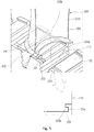
- FIG. 1 is a perspective view illustrating a rotor wheel mounted on a fixture for a bucket for a turbine blade according to one embodiment of the present disclosure
- FIGS. 2 to 5 are perspective views illustrating a fixed state using a first fixture of the fixture for a bucket for a turbine blade according to one embodiment of the present disclosure.
- the fixture for a bucket for a turbine blade includes: a rotor wheel 100 configured to have a plurality of dovetail grooves 110 having a predetermined diameter in axial direction of a rotor 2 and disposed to be spaced apart from each other along a circumferential direction and a platform seating part 120 formed between the dovetail grooves 110 and provided with a first insertion groove 122 in a circumferential direction; buckets 200 configured to have platforms 202 inserted into the dovetail grooves 110, respectively and a base platform 205 formed on an upper surface of the platform and provided with a second insertion groove 201 formed at a position facing the first insertion groove 122; a first fixture 300 configured to be fitted in an internal area formed by the first and second insertion grooves 122 and 201; a second fixture 400 configured to be positioned on a lower surface of a final bucket 200n to fix the final bucket 200n among the buckets 200 mounted on the rotor wheel 100
- the rotor wheel 100 corresponds to a component that is rotatably installed in a casing of a gas turbine and is rotated in one direction when high pressure steam is supplied to the rotor wheel 100 to rotate the bucket 200.
- the rotor wheel 100 has the plurality of dovetail grooves 110 provided in an axial direction at a predetermined interval and the platform seating part 120 constantly formed between the dovetail grooves, in which the dovetail groove 110 is not necessarily limited to the shape illustrated in the drawings.
- the platform seating part 120 is horizontally extended in the axial direction of the rotor wheel 100 and the extended upper surface is maintained in an adhering state to the lower surface of the base platform 205 when the bucket 200 is inserted into the dovetail groove 110.
- the bucket 200 includes the platform 202 having a shape corresponding to the dovetail groove 110, the base platform 205 formed at an upper portion of the platform 202 and having a plate shape, and a vane 210 extended to the upper portion of the base platform 205.
- a left side of the vane 210 corresponds to a suction surface 211a
- a right side thereof corresponds to a pressure surface 211b
- an upper end of the vane 210 is provided with a shroud 220.
- a left surface and a right surface of the shroud 220 are not flatly extended and therefore have a triangular shape.
- the plurality of buckets may be assembled in the adhering state when the plurality of buckets are assembled on the adjacent rotor wheel 100, thereby improving assembling safety.
- the bucket 200 has a front end provided with a leading edge 230 and a back end provided with a trailing edge 204, with respect to the vane 210.
- a lower side of the leading edge 230 is provided with the first insertion groove 122 and the lower surface of the base platform 205 facing the first insertion groove 122 is provided with the second insertion groove 201, such that the bucket 200 may be stably fixed at the leading position by the first fixture 300 to be described below.
- the bucket 200 is fitted in the plurality of dovetail grooves 110 formed along the circumferential direction of the rotor wheel 100 and a worker may sequentially assemble, for example, the bucket 200 clockwise or may assemble the bucket 200 in another direction according to a field situation.
- the platform seating part 120 is provided with the first insertion groove 122 along the circumferential direction of the rotor wheel 100, in which the first insertion groove 122 is formed to stably maintain the fixing of the bucket 200.
- the platform seating part 120 has the upper surface provided with the first insertion groove 122 and the back end provided with a stepped portion 120a steppe upwardly, in which the stepped portion 120a is maintained to be fixed in the adhering state in which the stepped portion 120a and a protrusion 120 adhere to each other when the protrusion 120b (see FIG. 5 ) protruding from the lower surface of the base platform 205 of the bucket 200 is engaged with the stepped portion 120a.
- the stepped portion 120a has a shape stepped from the back end at a predetermined height with respect to the upper surface of the platform seating part 120 and is maintained in the state in which it is engaged with the protrusion 120b, such that the bucket 200 is stably fixed on the rotor wheel 100 even when the high pressure steam is transferred to the bucket 200.
- the first insertion groove 122 is formed to face the second insertion groove 201 and the bucket 200 is maintained to be stably fixed at the trailing position corresponding to the front end of the bucket 200 by the first fixture 300 to be described below.
- the locked state between the stepped portion 120a and the protrusion 120b is maintained at the trailing position of the bucket 200 to prevent the bucket 200 from moving and separating due to the high pressure steam, such that the first mounted position of the bucket 200 is stably maintained.
- the bucket 200 when the high temperature steam moves to the bucket 200, the bucket 200 is stably maintained in the fixed state at both of the leading position and the trailing position of the foregoing bucket 200, such that the bucket may be maintained in the stably assembled state even when the bucket is re-assembled after the bucket is used for a long period of time or the bucket positioned at a specific position is separated for repairing. Therefore, the fixed stability for the bucket may be improved and the worker may conveniently and accurately perform the assembling operation for the bucket 200.
- the front surface of the bucket 200 is continuously applied with a high pressure and is applied with a force to move backwardly in the axial direction of the rotor wheel 100.
- the first fixture 300 may differently adjust a force to vertically lift up the bucket 200 in the dovetail groove 100 depending on the position. Further, as the first fixture 300 is inserted into a position close to the leading edge 230, the phenomenon of vertically lifting up the bucket 200 may be reduced, and as a result the separation due to the rotation of the rotor wheel 100 may be reduced.
- first insertion groove 122 may be formed in the shape illustrated in the drawings or the shape corresponding to the first fixture 300 to be described below or may be changed to have other shapes
- the first insertion groove 122 may be selectively disposed at a central position with respect to a center of the upper surface of the platform seating part 120 or any position between the front end and the center and the present embodiment describes only the case in which the first insertion groove 122 is formed at the position of the front end as illustrated in FIG. 2 or 3 .
- the first insertion groove 122 may be positioned at the center of the platform seating part 120 and may be formed at any position between the front end and the center of the platform seating part 120, if the first insertion groove 122 passes through the center but is not formed at the position of the back end, the bucket 200 may be maintained in the stably fixed state.
- the bucket 200 includes the platform 202 inserted into the dovetail groove 110 and the base platform 205 positioned at the upper portion of the platform 202 and having the second insertion groove 201 at the position facing the first insertion groove 122.
- the base platform 204 has a plate shape and is formed at a lower end of the vane 210.
- the first fixture 300 is fitted in the internal area formed when the first insertion groove 122 and the second insertion groove 201 are positioned in a state in which they face each other and is fitted in, for example, an arrow direction based on FIG. 5 .
- a worker uses a separate tool to maintain the buckets in a spread state and if the buckets are positioned at any position and then the tool is separated, the buckets are maintained in the mounted state by the force applied in the circumferential direction.
- the buckets are stably coupled in the dovetail groove 110.
- a front surface inside the foregoing second insertion groove 201 is provided with a partition wall 201a with respect to a direction in which the first fixture 300 is inserted to maintain the first fixture 300 in the state in which the first fixture 300 is inserted into a specific position when the first fixture 300 is inserted into the second insertion groove 201.
- the partition wall 201a may be accurately positioned at the defined insertion position when the first fixture 300 is inserted, and thus the first fixture 300 is prevented from being excessively inserted or unstably inserted into the first and second insertion grooves 122 and 201, such that the first fixture 300 maintains the stably coupled state.
- the bucket is maintained in the fixed state and the worker may easily install the plurality of buckets in the rotor wheel 100 by the foregoing method. Therefore, the stability of the installation work of the bucket 200 by the worker may be improved and the worker may more conveniently install the bucket 200.
- a second fixture 400 for fixing the final bucket 200n includes a body part 401 configured to be extended by a predetermined length so that it is inserted into the first insertion groove 122 and have a third insertion groove 420 formed at a position facing the second insertion groove 201, a protruding piece 410 configured to protrude upwardly from a position spaced apart from the third insertion groove 420 in a length direction of an upper surface of the body part 401, and blade parts 412 configured to be extended to be downwardly inclined backwardly from the length directions of the left and right sides of the protruding piece 410.
- the third insertion groove 420 is formed to penetrate in a vertical direction for an insertion of an auxiliary fixture 500 to be described below and the blade part 412 is extended to be downwardly inclined backwardly (left in the drawings) when viewed from the side surface of the body part 401.
- the second fixture 400 is assembled in the circumferential direction of the rotor wheel 100, when the second fixture 400 is inserted into the first and second insertion grooves 122 and 201 by the blade part 412 inclined at a predetermined angle, the insertion direction of the second fixture 400 may be guided and may be more easily inserted.
- the worker may predict the insertion position by maintaining the protruding piece 410 and the partition wall 201a in the adhering state when the fixture 400 is inserted into a space formed in the first and second insertion grooves 122 and 201.
- the second fixture 400 is used to allow the worker to stably install and fix the final bucket 200n.
- the final bucket 200n is not fixed at the right position with respect to the upper surface of the platform seating part 120 when viewing the bucket 200 from the front surface but is stably fixed at the left position by the second fixture 400 and the auxiliary fixture 500 to be described below.
- the worker inserts the first bucket 200a into the dovetail groove 110 and fixes it using the first fixture 300. Thereafter, the second to n-th buckets 200b to 200n are sequentially assembled in the adjacent dovetail grooves 110. For example, the second to n-th buckets 200b to 200n are sequentially assembled in the respective dovetail grooves 110 disposed clockwise. After the assembling as described above, the second fixture 400 is inserted into the second insertion groove 201 before the final bucket 200n is assembled.
- the worker inserts an adjustment member 600 from position A to position B at a gap formed between the upper surface of the platform seating part 120 and the lower surface of the base platform 205 to adjust the accurate insertion position of the second fixture 400.
- the gap is maintained a spaced state by a predetermined length in consideration of a thermal expansion.
- a triangular wedge is used as the adjustment member 600 and the adjustment member 600 is inserted in the gap formed between the platform seating part 120 and the lower surface of the base platform 205.
- the adjustment member 600 is pressed by a hammer or a tool (not illustrated) similar to the hammer from position A toward position B, the second fixture 400 moves from the space of the first and second insertion grooves 122 and 201 toward the right arrow direction with respect to the drawings by the adjustment member 600.
- the worker checks whether the third insertion groove 420 of the second fixture 400 matches the opening hole 203 and if not matched, adjusts the position of the auxiliary fixture 500 to perform the hole matching of the third insertion groove 420 and the opening hole 203.
- the reason why the worker perform the positioning using the adjustment member 600 is that the hole matching with the opening hole 203 formed in the final bucket 200n facing the third insertion groove 420 is accurately performed to easily insert the auxiliary fixture 500.
- the base platform 205 of the final bucket 200n is provided with the opening hole 203 opened downwardly from above, and thus the worker may easily confirm the matched state of the third insertion groove 420 and the opening hole 203 with the naked eye before the auxiliary fixture 500 is inserted. Therefore, when the third insertion groove 420 and the opening hole 203 match each other, the auxiliary fixture 500 is inserted.
- the stable position fixing and assembling of the final bucket 200n may be simultaneously performed.
- the auxiliary fixture 500 is inserted into the opening hole 203 formed in the final bucket 200n and the auxiliary fixture 500 is inserted into the second fixture 400 and then is fixed to the final bucket 200n while the upper surface of the auxiliary fixture 500 goes through caulking processing.
- the caulking processing means that the upper surface of the auxiliary fixture 500 is applied with a specific pressure to be intentionally deformed. By doing so, the auxiliary fixture 500 is prevented from being separated from the outer side of the final bucket 200n.
- the worker may more easily mount the final bucket 200n on the rotor wheel 100, thereby simultaneously improving the workability and work efficiency of the worker.
- the final bucket 200n has substantially the same structure as the foregoing bucket and is provided with an extending surface 222 to which a right surface (with respect to the drawing) of the shroud 220 is flatly extended, such that the final bucket 200n is maintained in the state in which it adheres to one surface of the shroud of the adjacent buckets 200.
- the assembling method of the turbine blade includes: a first bucket inserting step (ST100) of inserting the first bucket into any one of the plurality of dovetail grooves provided on the circumferential direction of the rotor wheel and then performing assembling in the state in which the first bucket is engaged with the leading position corresponding to the front end and the trailing position corresponding to the back end, respectively, with respect to the axial direction of the first bucket; a step (ST200) of fixing the first bucket using the fixture; a second to n-th bucket fixing step (ST300) of fixing the first bucket and then sequentially fixing the rest buckets to the dovetail grooves adjacently disposed to the first bucket; and a step (ST400) of inserting the final bucket into the dovetail groove and fixing the final bucket by positioning of the fixture.
- the regular position adjustment is performed on the fixture by selectively adjusting the insertion depth of the adjustment member inserted into the lower surface of the platform of the final bucket.
- the step (ST400) of fixing the final bucket includes a step (ST412) of performing the regular position adjustment is performed on the fixture and then inserting the auxiliary fixture coupled with the fixture at the outer side of the final bucket and a step (ST414) of performing the caulking processing on the upper surface of the auxiliary fixture to prevent the auxiliary fixture from being separated.
- the fixing is performed at the leading position and the trailing position of the first bucket to prevent the first bucket from moving to the front of the dovetail groove.
- the fixing of the first bucket is performed by the first fixture at the leading position (ST200) and the fixing method of the first fixture is already described and therefore the description of the fixing method will be omitted.
- the fixing of the rest bucket is sequentially performed along the circumferential direction of the rotor wheel (ST300) and the regular position adjustment of the second fixture is performed by adjusting the insertion depth of the adjustment member to insert the second fixture into the first and second insertion grooves before the final bucket 200n is assembled and then perform the regular position adjustment of the second fixture (ST400).
- the regular position adjustment of the second fixture means the operation of matching the third insertion groove of the second fixture and the opening hole formed on the upper surface of the base platform of the final bucket 200n each other.
- the insertion depth of the adjustment member is already described and therefore the detailed description thereof will be omitted.
- the worker adjusts the position of the second fixture and then inserts the auxiliary fixture into the second fixture (ST410) and performs the caulking processing on the upper surface of the auxiliary fixture as described above to prevent the auxiliary fixture from being separated to thereby prevent the final bucket from being separated from the dovetail groove.
- the worker may easily perform the mounting of the plurality of buckets and the final bucket mounted on the rotor wheel, thereby improving the workability of the worker and saving costs.
- the bucket may be stably maintained in the fixed state at two places corresponding to the positions of the leading edge and the trailing edge of the bucket to previously prevent the occurrence and failure of accidents due to the separation of the bucket.
Landscapes
- Engineering & Computer Science (AREA)
- Mechanical Engineering (AREA)
- General Engineering & Computer Science (AREA)
- Turbine Rotor Nozzle Sealing (AREA)
Applications Claiming Priority (1)
| Application Number | Priority Date | Filing Date | Title |
|---|---|---|---|
| KR1020150109462A KR101689085B1 (ko) | 2015-08-03 | 2015-08-03 | 터빈용 마지막 버켓 고정장치 및 이를 이용한 마지막 버켓의 조립 방법 |
Publications (2)
| Publication Number | Publication Date |
|---|---|
| EP3128131A1 true EP3128131A1 (fr) | 2017-02-08 |
| EP3128131B1 EP3128131B1 (fr) | 2019-03-20 |
Family
ID=56561314
Family Applications (1)
| Application Number | Title | Priority Date | Filing Date |
|---|---|---|---|
| EP16182436.2A Active EP3128131B1 (fr) | 2015-08-03 | 2016-08-02 | Procédé d'assemblage d'aubes de rotor de turbine et ensemble de fixation pour aubes de rotor de turbine |
Country Status (3)
| Country | Link |
|---|---|
| US (1) | US10358930B2 (fr) |
| EP (1) | EP3128131B1 (fr) |
| KR (1) | KR101689085B1 (fr) |
Cited By (1)
| Publication number | Priority date | Publication date | Assignee | Title |
|---|---|---|---|---|
| EP4411111A1 (fr) * | 2023-01-31 | 2024-08-07 | Doosan Enerbility Co., Ltd. | Agencement de rotor pour une turbine à gaz, turbine à gaz et procédé d'assemblage d'un agencement de rotor |
Families Citing this family (7)
| Publication number | Priority date | Publication date | Assignee | Title |
|---|---|---|---|---|
| KR101877677B1 (ko) * | 2017-05-12 | 2018-07-11 | 두산중공업 주식회사 | 회전체, 이를 제조하기 위한 회전체 제조방법 및 이를 포함하는 증기 터빈 |
| KR101953462B1 (ko) * | 2017-05-24 | 2019-02-28 | 두산중공업 주식회사 | 베인 어셈블리를갖는 가스터빈 |
| CN108106580B (zh) * | 2017-12-17 | 2020-05-01 | 北京工业大学 | 一种叶片型面测量夹装装置 |
| KR102193940B1 (ko) * | 2018-01-22 | 2020-12-22 | 두산중공업 주식회사 | 베인 링 조립체, 이의 조립방법 및 이를 포함하는 가스터빈 |
| KR102157899B1 (ko) * | 2019-04-25 | 2020-09-21 | 두산중공업 주식회사 | 터빈용 버켓 고정장치 및 이를 이용한 버켓 조립방법 |
| JP7738470B2 (ja) * | 2021-12-17 | 2025-09-12 | 三菱重工コンプレッサ株式会社 | 蒸気タービンのロータ、蒸気タービン、及び動翼の固定方法 |
| US12049833B1 (en) | 2023-05-26 | 2024-07-30 | General Electric Company | Rotor disks with disk post inserts and methods of assembling the same |
Citations (9)
| Publication number | Priority date | Publication date | Assignee | Title |
|---|---|---|---|---|
| US2843356A (en) * | 1954-04-05 | 1958-07-15 | Gen Electric | Turbo-machine rotor assembly |
| JPS61147302U (fr) * | 1985-03-06 | 1986-09-11 | ||
| US4676723A (en) * | 1986-03-26 | 1987-06-30 | Westinghouse Electric Corp. | Locking system for a turbine side entry blade |
| WO2009019126A1 (fr) * | 2007-08-08 | 2009-02-12 | Alstom Technology Ltd | Agencement de rotor de turbine |
| US20090290983A1 (en) * | 2008-05-26 | 2009-11-26 | Kabushiki Kaisha Toshiba | Turbine blade assembly and steam turbine |
| US20110229328A1 (en) * | 2010-03-17 | 2011-09-22 | Sudhir Rajagopalan | Turbomachine Blade Locking Structure Including Shape Memory Alloy |
| EP2613001A2 (fr) * | 2012-01-05 | 2013-07-10 | General Electric Company | Ensemble de rétention axiale de joint de bordure de rotor de turbine |
| EP2613000A2 (fr) * | 2012-01-05 | 2013-07-10 | General Electric Company | Système de rétention axiale de segments rotatifs d'une turbine et procedé associé |
| US20150167469A1 (en) * | 2013-12-17 | 2015-06-18 | General Electric Company | Turbine bucket closure assembly and methods of assembling the same |
Family Cites Families (6)
| Publication number | Priority date | Publication date | Assignee | Title |
|---|---|---|---|---|
| US4767247A (en) * | 1987-02-24 | 1988-08-30 | Westinghouse Electric Corp. | Apparatus and method for preventing relative blade motion in steam turbine |
| US4915587A (en) * | 1988-10-24 | 1990-04-10 | Westinghouse Electric Corp. | Apparatus for locking side entry blades into a rotor |
| US7121803B2 (en) * | 2002-12-26 | 2006-10-17 | General Electric Company | Compressor blade with dovetail slotted to reduce stress on the airfoil leading edge |
| KR20040100686A (ko) | 2003-05-23 | 2004-12-02 | 두산중공업 주식회사 | 발전 터빈의 로터와 버킷 결합구조 |
| FR2939832B1 (fr) * | 2008-12-11 | 2011-01-07 | Turbomeca | Roue de turbine equipee d'un dispositif de retenue axiale verrouillant des pales par rapport a un disque. |
| US8562301B2 (en) * | 2010-04-20 | 2013-10-22 | Hamilton Sundstrand Corporation | Turbine blade retention device |
-
2015
- 2015-08-03 KR KR1020150109462A patent/KR101689085B1/ko active Active
-
2016
- 2016-08-01 US US15/224,948 patent/US10358930B2/en active Active
- 2016-08-02 EP EP16182436.2A patent/EP3128131B1/fr active Active
Patent Citations (9)
| Publication number | Priority date | Publication date | Assignee | Title |
|---|---|---|---|---|
| US2843356A (en) * | 1954-04-05 | 1958-07-15 | Gen Electric | Turbo-machine rotor assembly |
| JPS61147302U (fr) * | 1985-03-06 | 1986-09-11 | ||
| US4676723A (en) * | 1986-03-26 | 1987-06-30 | Westinghouse Electric Corp. | Locking system for a turbine side entry blade |
| WO2009019126A1 (fr) * | 2007-08-08 | 2009-02-12 | Alstom Technology Ltd | Agencement de rotor de turbine |
| US20090290983A1 (en) * | 2008-05-26 | 2009-11-26 | Kabushiki Kaisha Toshiba | Turbine blade assembly and steam turbine |
| US20110229328A1 (en) * | 2010-03-17 | 2011-09-22 | Sudhir Rajagopalan | Turbomachine Blade Locking Structure Including Shape Memory Alloy |
| EP2613001A2 (fr) * | 2012-01-05 | 2013-07-10 | General Electric Company | Ensemble de rétention axiale de joint de bordure de rotor de turbine |
| EP2613000A2 (fr) * | 2012-01-05 | 2013-07-10 | General Electric Company | Système de rétention axiale de segments rotatifs d'une turbine et procedé associé |
| US20150167469A1 (en) * | 2013-12-17 | 2015-06-18 | General Electric Company | Turbine bucket closure assembly and methods of assembling the same |
Cited By (1)
| Publication number | Priority date | Publication date | Assignee | Title |
|---|---|---|---|---|
| EP4411111A1 (fr) * | 2023-01-31 | 2024-08-07 | Doosan Enerbility Co., Ltd. | Agencement de rotor pour une turbine à gaz, turbine à gaz et procédé d'assemblage d'un agencement de rotor |
Also Published As
| Publication number | Publication date |
|---|---|
| EP3128131B1 (fr) | 2019-03-20 |
| US10358930B2 (en) | 2019-07-23 |
| US20170037735A1 (en) | 2017-02-09 |
| KR101689085B1 (ko) | 2017-01-02 |
Similar Documents
| Publication | Publication Date | Title |
|---|---|---|
| EP3128131A1 (fr) | Procédé d'assemblage d'aubes de rotor de turbine et ensemble de fixation pour aubes de rotor de turbine | |
| EP2660426B1 (fr) | Ensemble turbine | |
| US9309782B2 (en) | Flat bottom damper pin for turbine blades | |
| US8662852B2 (en) | Swing axial-entry for closure bucket used for tangential row in steam turbine | |
| EP1808577B1 (fr) | Ensemble d'aubes statoriques soudées pour turbine à vapeur | |
| EP2070619B1 (fr) | Procédé d'usinage d'un disque de turbine | |
| EP2503102A2 (fr) | Rotor doté de plateformes inter-aubes | |
| CN105683508B (zh) | 涡轮机转子组件和方法 | |
| EP1077308B1 (fr) | Aube ou aube de guidage de turbomachine avec un repère d' usinage capable de survivre | |
| US20080193290A1 (en) | Hook Ring Segment For A Compressor Vane | |
| US8591192B2 (en) | Turbomachine rotor assembly and method | |
| CN103502653A (zh) | 具有叶片的轴向保持装置的涡轮机转子 | |
| US8562292B2 (en) | Steam turbine singlet interface for margin stage nozzles with pinned or bolted inner ring | |
| CA2707510C (fr) | Agencement de rotor de turbine | |
| EP3396109B1 (fr) | Ensemble rotor pour une turbine à vapeur, turbine à vapeur correspondante et procédé de fabrication dudit ensemble rotor | |
| EP2855896B1 (fr) | Dispositif anti-erreur pour aubes de stator | |
| EP2863016A1 (fr) | Turbine avec moyens de fixation des aubes | |
| US7497658B2 (en) | Stacked reaction steam turbine stator assembly | |
| US20170159466A1 (en) | Guide vane segment with radial securing elements | |
| KR101607780B1 (ko) | 도브테일의 고정장치 및 이의 고정방법 | |
| US20170276145A1 (en) | Blade with a platform and a hollow bumper |
Legal Events
| Date | Code | Title | Description |
|---|---|---|---|
| PUAI | Public reference made under article 153(3) epc to a published international application that has entered the european phase |
Free format text: ORIGINAL CODE: 0009012 |
|
| STAA | Information on the status of an ep patent application or granted ep patent |
Free format text: STATUS: REQUEST FOR EXAMINATION WAS MADE |
|
| 17P | Request for examination filed |
Effective date: 20160802 |
|
| AK | Designated contracting states |
Kind code of ref document: A1 Designated state(s): AL AT BE BG CH CY CZ DE DK EE ES FI FR GB GR HR HU IE IS IT LI LT LU LV MC MK MT NL NO PL PT RO RS SE SI SK SM TR |
|
| AX | Request for extension of the european patent |
Extension state: BA ME |
|
| RBV | Designated contracting states (corrected) |
Designated state(s): AL AT BE BG CH CY CZ DE DK EE ES FI FR GB GR HR HU IE IS IT LI LT LU LV MC MK MT NL NO PL PT RO RS SE SI SK SM TR |
|
| STAA | Information on the status of an ep patent application or granted ep patent |
Free format text: STATUS: EXAMINATION IS IN PROGRESS |
|
| 17Q | First examination report despatched |
Effective date: 20180815 |
|
| GRAP | Despatch of communication of intention to grant a patent |
Free format text: ORIGINAL CODE: EPIDOSNIGR1 |
|
| STAA | Information on the status of an ep patent application or granted ep patent |
Free format text: STATUS: GRANT OF PATENT IS INTENDED |
|
| INTG | Intention to grant announced |
Effective date: 20181017 |
|
| GRAS | Grant fee paid |
Free format text: ORIGINAL CODE: EPIDOSNIGR3 |
|
| GRAA | (expected) grant |
Free format text: ORIGINAL CODE: 0009210 |
|
| STAA | Information on the status of an ep patent application or granted ep patent |
Free format text: STATUS: THE PATENT HAS BEEN GRANTED |
|
| AK | Designated contracting states |
Kind code of ref document: B1 Designated state(s): AL AT BE BG CH CY CZ DE DK EE ES FI FR GB GR HR HU IE IS IT LI LT LU LV MC MK MT NL NO PL PT RO RS SE SI SK SM TR |
|
| REG | Reference to a national code |
Ref country code: GB Ref legal event code: FG4D |
|
| REG | Reference to a national code |
Ref country code: CH Ref legal event code: EP |
|
| REG | Reference to a national code |
Ref country code: DE Ref legal event code: R096 Ref document number: 602016011213 Country of ref document: DE |
|
| REG | Reference to a national code |
Ref country code: AT Ref legal event code: REF Ref document number: 1110732 Country of ref document: AT Kind code of ref document: T Effective date: 20190415 |
|
| REG | Reference to a national code |
Ref country code: IE Ref legal event code: FG4D |
|
| REG | Reference to a national code |
Ref country code: NL Ref legal event code: MP Effective date: 20190320 |
|
| PG25 | Lapsed in a contracting state [announced via postgrant information from national office to epo] |
Ref country code: NO Free format text: LAPSE BECAUSE OF FAILURE TO SUBMIT A TRANSLATION OF THE DESCRIPTION OR TO PAY THE FEE WITHIN THE PRESCRIBED TIME-LIMIT Effective date: 20190620 Ref country code: FI Free format text: LAPSE BECAUSE OF FAILURE TO SUBMIT A TRANSLATION OF THE DESCRIPTION OR TO PAY THE FEE WITHIN THE PRESCRIBED TIME-LIMIT Effective date: 20190320 Ref country code: LT Free format text: LAPSE BECAUSE OF FAILURE TO SUBMIT A TRANSLATION OF THE DESCRIPTION OR TO PAY THE FEE WITHIN THE PRESCRIBED TIME-LIMIT Effective date: 20190320 Ref country code: SE Free format text: LAPSE BECAUSE OF FAILURE TO SUBMIT A TRANSLATION OF THE DESCRIPTION OR TO PAY THE FEE WITHIN THE PRESCRIBED TIME-LIMIT Effective date: 20190320 |
|
| REG | Reference to a national code |
Ref country code: LT Ref legal event code: MG4D |
|
| PG25 | Lapsed in a contracting state [announced via postgrant information from national office to epo] |
Ref country code: HR Free format text: LAPSE BECAUSE OF FAILURE TO SUBMIT A TRANSLATION OF THE DESCRIPTION OR TO PAY THE FEE WITHIN THE PRESCRIBED TIME-LIMIT Effective date: 20190320 Ref country code: RS Free format text: LAPSE BECAUSE OF FAILURE TO SUBMIT A TRANSLATION OF THE DESCRIPTION OR TO PAY THE FEE WITHIN THE PRESCRIBED TIME-LIMIT Effective date: 20190320 Ref country code: LV Free format text: LAPSE BECAUSE OF FAILURE TO SUBMIT A TRANSLATION OF THE DESCRIPTION OR TO PAY THE FEE WITHIN THE PRESCRIBED TIME-LIMIT Effective date: 20190320 Ref country code: BG Free format text: LAPSE BECAUSE OF FAILURE TO SUBMIT A TRANSLATION OF THE DESCRIPTION OR TO PAY THE FEE WITHIN THE PRESCRIBED TIME-LIMIT Effective date: 20190620 Ref country code: GR Free format text: LAPSE BECAUSE OF FAILURE TO SUBMIT A TRANSLATION OF THE DESCRIPTION OR TO PAY THE FEE WITHIN THE PRESCRIBED TIME-LIMIT Effective date: 20190621 Ref country code: NL Free format text: LAPSE BECAUSE OF FAILURE TO SUBMIT A TRANSLATION OF THE DESCRIPTION OR TO PAY THE FEE WITHIN THE PRESCRIBED TIME-LIMIT Effective date: 20190320 |
|
| REG | Reference to a national code |
Ref country code: AT Ref legal event code: MK05 Ref document number: 1110732 Country of ref document: AT Kind code of ref document: T Effective date: 20190320 |
|
| PG25 | Lapsed in a contracting state [announced via postgrant information from national office to epo] |
Ref country code: PT Free format text: LAPSE BECAUSE OF FAILURE TO SUBMIT A TRANSLATION OF THE DESCRIPTION OR TO PAY THE FEE WITHIN THE PRESCRIBED TIME-LIMIT Effective date: 20190720 Ref country code: AL Free format text: LAPSE BECAUSE OF FAILURE TO SUBMIT A TRANSLATION OF THE DESCRIPTION OR TO PAY THE FEE WITHIN THE PRESCRIBED TIME-LIMIT Effective date: 20190320 Ref country code: ES Free format text: LAPSE BECAUSE OF FAILURE TO SUBMIT A TRANSLATION OF THE DESCRIPTION OR TO PAY THE FEE WITHIN THE PRESCRIBED TIME-LIMIT Effective date: 20190320 Ref country code: RO Free format text: LAPSE BECAUSE OF FAILURE TO SUBMIT A TRANSLATION OF THE DESCRIPTION OR TO PAY THE FEE WITHIN THE PRESCRIBED TIME-LIMIT Effective date: 20190320 Ref country code: IT Free format text: LAPSE BECAUSE OF FAILURE TO SUBMIT A TRANSLATION OF THE DESCRIPTION OR TO PAY THE FEE WITHIN THE PRESCRIBED TIME-LIMIT Effective date: 20190320 Ref country code: CZ Free format text: LAPSE BECAUSE OF FAILURE TO SUBMIT A TRANSLATION OF THE DESCRIPTION OR TO PAY THE FEE WITHIN THE PRESCRIBED TIME-LIMIT Effective date: 20190320 Ref country code: SK Free format text: LAPSE BECAUSE OF FAILURE TO SUBMIT A TRANSLATION OF THE DESCRIPTION OR TO PAY THE FEE WITHIN THE PRESCRIBED TIME-LIMIT Effective date: 20190320 Ref country code: EE Free format text: LAPSE BECAUSE OF FAILURE TO SUBMIT A TRANSLATION OF THE DESCRIPTION OR TO PAY THE FEE WITHIN THE PRESCRIBED TIME-LIMIT Effective date: 20190320 |
|
| PG25 | Lapsed in a contracting state [announced via postgrant information from national office to epo] |
Ref country code: PL Free format text: LAPSE BECAUSE OF FAILURE TO SUBMIT A TRANSLATION OF THE DESCRIPTION OR TO PAY THE FEE WITHIN THE PRESCRIBED TIME-LIMIT Effective date: 20190320 Ref country code: SM Free format text: LAPSE BECAUSE OF FAILURE TO SUBMIT A TRANSLATION OF THE DESCRIPTION OR TO PAY THE FEE WITHIN THE PRESCRIBED TIME-LIMIT Effective date: 20190320 |
|
| PG25 | Lapsed in a contracting state [announced via postgrant information from national office to epo] |
Ref country code: IS Free format text: LAPSE BECAUSE OF FAILURE TO SUBMIT A TRANSLATION OF THE DESCRIPTION OR TO PAY THE FEE WITHIN THE PRESCRIBED TIME-LIMIT Effective date: 20190720 Ref country code: AT Free format text: LAPSE BECAUSE OF FAILURE TO SUBMIT A TRANSLATION OF THE DESCRIPTION OR TO PAY THE FEE WITHIN THE PRESCRIBED TIME-LIMIT Effective date: 20190320 |
|
| REG | Reference to a national code |
Ref country code: DE Ref legal event code: R097 Ref document number: 602016011213 Country of ref document: DE |
|
| PLBE | No opposition filed within time limit |
Free format text: ORIGINAL CODE: 0009261 |
|
| STAA | Information on the status of an ep patent application or granted ep patent |
Free format text: STATUS: NO OPPOSITION FILED WITHIN TIME LIMIT |
|
| PG25 | Lapsed in a contracting state [announced via postgrant information from national office to epo] |
Ref country code: DK Free format text: LAPSE BECAUSE OF FAILURE TO SUBMIT A TRANSLATION OF THE DESCRIPTION OR TO PAY THE FEE WITHIN THE PRESCRIBED TIME-LIMIT Effective date: 20190320 |
|
| 26N | No opposition filed |
Effective date: 20200102 |
|
| PG25 | Lapsed in a contracting state [announced via postgrant information from national office to epo] |
Ref country code: SI Free format text: LAPSE BECAUSE OF FAILURE TO SUBMIT A TRANSLATION OF THE DESCRIPTION OR TO PAY THE FEE WITHIN THE PRESCRIBED TIME-LIMIT Effective date: 20190320 |
|
| PG25 | Lapsed in a contracting state [announced via postgrant information from national office to epo] |
Ref country code: TR Free format text: LAPSE BECAUSE OF FAILURE TO SUBMIT A TRANSLATION OF THE DESCRIPTION OR TO PAY THE FEE WITHIN THE PRESCRIBED TIME-LIMIT Effective date: 20190320 |
|
| PG25 | Lapsed in a contracting state [announced via postgrant information from national office to epo] |
Ref country code: LI Free format text: LAPSE BECAUSE OF NON-PAYMENT OF DUE FEES Effective date: 20190831 Ref country code: CH Free format text: LAPSE BECAUSE OF NON-PAYMENT OF DUE FEES Effective date: 20190831 Ref country code: MC Free format text: LAPSE BECAUSE OF FAILURE TO SUBMIT A TRANSLATION OF THE DESCRIPTION OR TO PAY THE FEE WITHIN THE PRESCRIBED TIME-LIMIT Effective date: 20190320 Ref country code: LU Free format text: LAPSE BECAUSE OF NON-PAYMENT OF DUE FEES Effective date: 20190802 |
|
| REG | Reference to a national code |
Ref country code: BE Ref legal event code: MM Effective date: 20190831 |
|
| PG25 | Lapsed in a contracting state [announced via postgrant information from national office to epo] |
Ref country code: IE Free format text: LAPSE BECAUSE OF NON-PAYMENT OF DUE FEES Effective date: 20190802 Ref country code: FR Free format text: LAPSE BECAUSE OF NON-PAYMENT OF DUE FEES Effective date: 20190831 |
|
| PG25 | Lapsed in a contracting state [announced via postgrant information from national office to epo] |
Ref country code: BE Free format text: LAPSE BECAUSE OF NON-PAYMENT OF DUE FEES Effective date: 20190831 |
|
| PG25 | Lapsed in a contracting state [announced via postgrant information from national office to epo] |
Ref country code: CY Free format text: LAPSE BECAUSE OF FAILURE TO SUBMIT A TRANSLATION OF THE DESCRIPTION OR TO PAY THE FEE WITHIN THE PRESCRIBED TIME-LIMIT Effective date: 20190320 |
|
| PG25 | Lapsed in a contracting state [announced via postgrant information from national office to epo] |
Ref country code: HU Free format text: LAPSE BECAUSE OF FAILURE TO SUBMIT A TRANSLATION OF THE DESCRIPTION OR TO PAY THE FEE WITHIN THE PRESCRIBED TIME-LIMIT; INVALID AB INITIO Effective date: 20160802 Ref country code: MT Free format text: LAPSE BECAUSE OF FAILURE TO SUBMIT A TRANSLATION OF THE DESCRIPTION OR TO PAY THE FEE WITHIN THE PRESCRIBED TIME-LIMIT Effective date: 20190320 |
|
| PG25 | Lapsed in a contracting state [announced via postgrant information from national office to epo] |
Ref country code: MK Free format text: LAPSE BECAUSE OF FAILURE TO SUBMIT A TRANSLATION OF THE DESCRIPTION OR TO PAY THE FEE WITHIN THE PRESCRIBED TIME-LIMIT Effective date: 20190320 |
|
| REG | Reference to a national code |
Ref country code: DE Ref legal event code: R082 Ref document number: 602016011213 Country of ref document: DE Representative=s name: TER MEER STEINMEISTER & PARTNER PATENTANWAELTE, DE |
|
| PGFP | Annual fee paid to national office [announced via postgrant information from national office to epo] |
Ref country code: GB Payment date: 20250612 Year of fee payment: 10 |
|
| PGFP | Annual fee paid to national office [announced via postgrant information from national office to epo] |
Ref country code: DE Payment date: 20250611 Year of fee payment: 10 |