EP3128151B1 - Gasturbinenkreislaufausrüstung, ausrüstung zur rückgewinnung von co2 aus abgas und verfahren zur rückgewinnung von abwärme aus verbrennungsabgasen - Google Patents
Gasturbinenkreislaufausrüstung, ausrüstung zur rückgewinnung von co2 aus abgas und verfahren zur rückgewinnung von abwärme aus verbrennungsabgasen Download PDFInfo
- Publication number
- EP3128151B1 EP3128151B1 EP15792546.2A EP15792546A EP3128151B1 EP 3128151 B1 EP3128151 B1 EP 3128151B1 EP 15792546 A EP15792546 A EP 15792546A EP 3128151 B1 EP3128151 B1 EP 3128151B1
- Authority
- EP
- European Patent Office
- Prior art keywords
- heat exchange
- compressed air
- flue gas
- supply water
- combustion flue
- Prior art date
- Legal status (The legal status is an assumption and is not a legal conclusion. Google has not performed a legal analysis and makes no representation as to the accuracy of the status listed.)
- Active
Links
Images


Classifications
-
- F—MECHANICAL ENGINEERING; LIGHTING; HEATING; WEAPONS; BLASTING
- F02—COMBUSTION ENGINES; HOT-GAS OR COMBUSTION-PRODUCT ENGINE PLANTS
- F02C—GAS-TURBINE PLANTS; AIR INTAKES FOR JET-PROPULSION PLANTS; CONTROLLING FUEL SUPPLY IN AIR-BREATHING JET-PROPULSION PLANTS
- F02C6/00—Plural gas-turbine plants; Combinations of gas-turbine plants with other apparatus; Adaptations of gas-turbine plants for special use
- F02C6/04—Gas-turbine plants providing heated or pressurised working fluid for other apparatus, e.g. without mechanical power output
- F02C6/06—Gas-turbine plants providing heated or pressurised working fluid for other apparatus, e.g. without mechanical power output providing compressed gas
-
- F—MECHANICAL ENGINEERING; LIGHTING; HEATING; WEAPONS; BLASTING
- F02—COMBUSTION ENGINES; HOT-GAS OR COMBUSTION-PRODUCT ENGINE PLANTS
- F02C—GAS-TURBINE PLANTS; AIR INTAKES FOR JET-PROPULSION PLANTS; CONTROLLING FUEL SUPPLY IN AIR-BREATHING JET-PROPULSION PLANTS
- F02C7/00—Features, components parts, details or accessories, not provided for in, or of interest apart form groups F02C1/00 - F02C6/00; Air intakes for jet-propulsion plants
- F02C7/08—Heating air supply before combustion, e.g. by exhaust gases
-
- B—PERFORMING OPERATIONS; TRANSPORTING
- B01—PHYSICAL OR CHEMICAL PROCESSES OR APPARATUS IN GENERAL
- B01D—SEPARATION
- B01D53/00—Separation of gases or vapours; Recovering vapours of volatile solvents from gases; Chemical or biological purification of waste gases, e.g. engine exhaust gases, smoke, fumes, flue gases, aerosols
- B01D53/14—Separation of gases or vapours; Recovering vapours of volatile solvents from gases; Chemical or biological purification of waste gases, e.g. engine exhaust gases, smoke, fumes, flue gases, aerosols by absorption
- B01D53/1425—Regeneration of liquid absorbents
-
- B—PERFORMING OPERATIONS; TRANSPORTING
- B01—PHYSICAL OR CHEMICAL PROCESSES OR APPARATUS IN GENERAL
- B01D—SEPARATION
- B01D53/00—Separation of gases or vapours; Recovering vapours of volatile solvents from gases; Chemical or biological purification of waste gases, e.g. engine exhaust gases, smoke, fumes, flue gases, aerosols
- B01D53/14—Separation of gases or vapours; Recovering vapours of volatile solvents from gases; Chemical or biological purification of waste gases, e.g. engine exhaust gases, smoke, fumes, flue gases, aerosols by absorption
- B01D53/1456—Removing acid components
- B01D53/1475—Removing carbon dioxide
-
- F—MECHANICAL ENGINEERING; LIGHTING; HEATING; WEAPONS; BLASTING
- F01—MACHINES OR ENGINES IN GENERAL; ENGINE PLANTS IN GENERAL; STEAM ENGINES
- F01K—STEAM ENGINE PLANTS; STEAM ACCUMULATORS; ENGINE PLANTS NOT OTHERWISE PROVIDED FOR; ENGINES USING SPECIAL WORKING FLUIDS OR CYCLES
- F01K21/00—Steam engine plants not otherwise provided for
- F01K21/04—Steam engine plants not otherwise provided for using mixtures of steam and gas; Plants generating or heating steam by bringing water or steam into direct contact with hot gas
- F01K21/047—Steam engine plants not otherwise provided for using mixtures of steam and gas; Plants generating or heating steam by bringing water or steam into direct contact with hot gas having at least one combustion gas turbine
-
- F—MECHANICAL ENGINEERING; LIGHTING; HEATING; WEAPONS; BLASTING
- F02—COMBUSTION ENGINES; HOT-GAS OR COMBUSTION-PRODUCT ENGINE PLANTS
- F02C—GAS-TURBINE PLANTS; AIR INTAKES FOR JET-PROPULSION PLANTS; CONTROLLING FUEL SUPPLY IN AIR-BREATHING JET-PROPULSION PLANTS
- F02C3/00—Gas-turbine plants characterised by the use of combustion products as the working fluid
- F02C3/04—Gas-turbine plants characterised by the use of combustion products as the working fluid having a turbine driving a compressor
-
- F—MECHANICAL ENGINEERING; LIGHTING; HEATING; WEAPONS; BLASTING
- F02—COMBUSTION ENGINES; HOT-GAS OR COMBUSTION-PRODUCT ENGINE PLANTS
- F02C—GAS-TURBINE PLANTS; AIR INTAKES FOR JET-PROPULSION PLANTS; CONTROLLING FUEL SUPPLY IN AIR-BREATHING JET-PROPULSION PLANTS
- F02C3/00—Gas-turbine plants characterised by the use of combustion products as the working fluid
- F02C3/20—Gas-turbine plants characterised by the use of combustion products as the working fluid using a special fuel, oxidant, or dilution fluid to generate the combustion products
- F02C3/30—Adding water, steam or other fluids for influencing combustion, e.g. to obtain cleaner exhaust gases
- F02C3/305—Increasing the power, speed, torque or efficiency of a gas turbine or the thrust of a turbojet engine by injecting or adding water, steam or other fluids
-
- F—MECHANICAL ENGINEERING; LIGHTING; HEATING; WEAPONS; BLASTING
- F02—COMBUSTION ENGINES; HOT-GAS OR COMBUSTION-PRODUCT ENGINE PLANTS
- F02C—GAS-TURBINE PLANTS; AIR INTAKES FOR JET-PROPULSION PLANTS; CONTROLLING FUEL SUPPLY IN AIR-BREATHING JET-PROPULSION PLANTS
- F02C7/00—Features, components parts, details or accessories, not provided for in, or of interest apart form groups F02C1/00 - F02C6/00; Air intakes for jet-propulsion plants
- F02C7/12—Cooling of plants
- F02C7/14—Cooling of plants of fluids in the plant, e.g. lubricant or fuel
- F02C7/141—Cooling of plants of fluids in the plant, e.g. lubricant or fuel of working fluid
- F02C7/143—Cooling of plants of fluids in the plant, e.g. lubricant or fuel of working fluid before or between the compressor stages
- F02C7/1435—Cooling of plants of fluids in the plant, e.g. lubricant or fuel of working fluid before or between the compressor stages by water injection
-
- F—MECHANICAL ENGINEERING; LIGHTING; HEATING; WEAPONS; BLASTING
- F22—STEAM GENERATION
- F22B—METHODS OF STEAM GENERATION; STEAM BOILERS
- F22B1/00—Methods of steam generation characterised by form of heating method
- F22B1/02—Methods of steam generation characterised by form of heating method by exploitation of the heat content of hot heat carriers
- F22B1/18—Methods of steam generation characterised by form of heating method by exploitation of the heat content of hot heat carriers the heat carrier being a hot gas, e.g. waste gas such as exhaust gas of internal-combustion engines
- F22B1/1807—Methods of steam generation characterised by form of heating method by exploitation of the heat content of hot heat carriers the heat carrier being a hot gas, e.g. waste gas such as exhaust gas of internal-combustion engines using the exhaust gases of combustion engines
- F22B1/1815—Methods of steam generation characterised by form of heating method by exploitation of the heat content of hot heat carriers the heat carrier being a hot gas, e.g. waste gas such as exhaust gas of internal-combustion engines using the exhaust gases of combustion engines using the exhaust gases of gas-turbines
-
- F—MECHANICAL ENGINEERING; LIGHTING; HEATING; WEAPONS; BLASTING
- F28—HEAT EXCHANGE IN GENERAL
- F28C—HEAT-EXCHANGE APPARATUS, NOT PROVIDED FOR IN ANOTHER SUBCLASS, IN WHICH THE HEAT-EXCHANGE MEDIA COME INTO DIRECT CONTACT WITHOUT CHEMICAL INTERACTION
- F28C1/00—Direct-contact trickle coolers, e.g. cooling towers
- F28C1/14—Direct-contact trickle coolers, e.g. cooling towers comprising also a non-direct contact heat exchange
-
- B—PERFORMING OPERATIONS; TRANSPORTING
- B01—PHYSICAL OR CHEMICAL PROCESSES OR APPARATUS IN GENERAL
- B01D—SEPARATION
- B01D2252/00—Absorbents, i.e. solvents and liquid materials for gas absorption
- B01D2252/20—Organic absorbents
- B01D2252/204—Amines
-
- B—PERFORMING OPERATIONS; TRANSPORTING
- B01—PHYSICAL OR CHEMICAL PROCESSES OR APPARATUS IN GENERAL
- B01D—SEPARATION
- B01D2257/00—Components to be removed
- B01D2257/50—Carbon oxides
- B01D2257/504—Carbon dioxide
-
- B—PERFORMING OPERATIONS; TRANSPORTING
- B01—PHYSICAL OR CHEMICAL PROCESSES OR APPARATUS IN GENERAL
- B01D—SEPARATION
- B01D2258/00—Sources of waste gases
- B01D2258/02—Other waste gases
- B01D2258/0283—Flue gases
-
- B—PERFORMING OPERATIONS; TRANSPORTING
- B01—PHYSICAL OR CHEMICAL PROCESSES OR APPARATUS IN GENERAL
- B01D—SEPARATION
- B01D53/00—Separation of gases or vapours; Recovering vapours of volatile solvents from gases; Chemical or biological purification of waste gases, e.g. engine exhaust gases, smoke, fumes, flue gases, aerosols
- B01D53/34—Chemical or biological purification of waste gases
- B01D53/46—Removing components of defined structure
- B01D53/62—Carbon oxides
-
- F—MECHANICAL ENGINEERING; LIGHTING; HEATING; WEAPONS; BLASTING
- F05—INDEXING SCHEMES RELATING TO ENGINES OR PUMPS IN VARIOUS SUBCLASSES OF CLASSES F01-F04
- F05D—INDEXING SCHEME FOR ASPECTS RELATING TO NON-POSITIVE-DISPLACEMENT MACHINES OR ENGINES, GAS-TURBINES OR JET-PROPULSION PLANTS
- F05D2220/00—Application
- F05D2220/30—Application in turbines
- F05D2220/32—Application in turbines in gas turbines
-
- F—MECHANICAL ENGINEERING; LIGHTING; HEATING; WEAPONS; BLASTING
- F05—INDEXING SCHEMES RELATING TO ENGINES OR PUMPS IN VARIOUS SUBCLASSES OF CLASSES F01-F04
- F05D—INDEXING SCHEME FOR ASPECTS RELATING TO NON-POSITIVE-DISPLACEMENT MACHINES OR ENGINES, GAS-TURBINES OR JET-PROPULSION PLANTS
- F05D2220/00—Application
- F05D2220/60—Application making use of surplus or waste energy
-
- F—MECHANICAL ENGINEERING; LIGHTING; HEATING; WEAPONS; BLASTING
- F05—INDEXING SCHEMES RELATING TO ENGINES OR PUMPS IN VARIOUS SUBCLASSES OF CLASSES F01-F04
- F05D—INDEXING SCHEME FOR ASPECTS RELATING TO NON-POSITIVE-DISPLACEMENT MACHINES OR ENGINES, GAS-TURBINES OR JET-PROPULSION PLANTS
- F05D2220/00—Application
- F05D2220/70—Application in combination with
- F05D2220/75—Application in combination with equipment using fuel having a low calorific value, e.g. low BTU fuel, waste end, syngas, biomass fuel or flare gas
-
- F—MECHANICAL ENGINEERING; LIGHTING; HEATING; WEAPONS; BLASTING
- F05—INDEXING SCHEMES RELATING TO ENGINES OR PUMPS IN VARIOUS SUBCLASSES OF CLASSES F01-F04
- F05D—INDEXING SCHEME FOR ASPECTS RELATING TO NON-POSITIVE-DISPLACEMENT MACHINES OR ENGINES, GAS-TURBINES OR JET-PROPULSION PLANTS
- F05D2220/00—Application
- F05D2220/70—Application in combination with
- F05D2220/76—Application in combination with an electrical generator
-
- F—MECHANICAL ENGINEERING; LIGHTING; HEATING; WEAPONS; BLASTING
- F05—INDEXING SCHEMES RELATING TO ENGINES OR PUMPS IN VARIOUS SUBCLASSES OF CLASSES F01-F04
- F05D—INDEXING SCHEME FOR ASPECTS RELATING TO NON-POSITIVE-DISPLACEMENT MACHINES OR ENGINES, GAS-TURBINES OR JET-PROPULSION PLANTS
- F05D2240/00—Components
- F05D2240/35—Combustors or associated equipment
-
- F—MECHANICAL ENGINEERING; LIGHTING; HEATING; WEAPONS; BLASTING
- F05—INDEXING SCHEMES RELATING TO ENGINES OR PUMPS IN VARIOUS SUBCLASSES OF CLASSES F01-F04
- F05D—INDEXING SCHEME FOR ASPECTS RELATING TO NON-POSITIVE-DISPLACEMENT MACHINES OR ENGINES, GAS-TURBINES OR JET-PROPULSION PLANTS
- F05D2260/00—Function
- F05D2260/20—Heat transfer, e.g. cooling
- F05D2260/211—Heat transfer, e.g. cooling by intercooling, e.g. during a compression cycle
-
- F—MECHANICAL ENGINEERING; LIGHTING; HEATING; WEAPONS; BLASTING
- F05—INDEXING SCHEMES RELATING TO ENGINES OR PUMPS IN VARIOUS SUBCLASSES OF CLASSES F01-F04
- F05D—INDEXING SCHEME FOR ASPECTS RELATING TO NON-POSITIVE-DISPLACEMENT MACHINES OR ENGINES, GAS-TURBINES OR JET-PROPULSION PLANTS
- F05D2260/00—Function
- F05D2260/20—Heat transfer, e.g. cooling
- F05D2260/212—Heat transfer, e.g. cooling by water injection
-
- F—MECHANICAL ENGINEERING; LIGHTING; HEATING; WEAPONS; BLASTING
- F05—INDEXING SCHEMES RELATING TO ENGINES OR PUMPS IN VARIOUS SUBCLASSES OF CLASSES F01-F04
- F05D—INDEXING SCHEME FOR ASPECTS RELATING TO NON-POSITIVE-DISPLACEMENT MACHINES OR ENGINES, GAS-TURBINES OR JET-PROPULSION PLANTS
- F05D2260/00—Function
- F05D2260/20—Heat transfer, e.g. cooling
- F05D2260/213—Heat transfer, e.g. cooling by the provision of a heat exchanger within the cooling circuit
-
- F—MECHANICAL ENGINEERING; LIGHTING; HEATING; WEAPONS; BLASTING
- F05—INDEXING SCHEMES RELATING TO ENGINES OR PUMPS IN VARIOUS SUBCLASSES OF CLASSES F01-F04
- F05D—INDEXING SCHEME FOR ASPECTS RELATING TO NON-POSITIVE-DISPLACEMENT MACHINES OR ENGINES, GAS-TURBINES OR JET-PROPULSION PLANTS
- F05D2260/00—Function
- F05D2260/60—Fluid transfer
- F05D2260/61—Removal of CO2
-
- F—MECHANICAL ENGINEERING; LIGHTING; HEATING; WEAPONS; BLASTING
- F28—HEAT EXCHANGE IN GENERAL
- F28C—HEAT-EXCHANGE APPARATUS, NOT PROVIDED FOR IN ANOTHER SUBCLASS, IN WHICH THE HEAT-EXCHANGE MEDIA COME INTO DIRECT CONTACT WITHOUT CHEMICAL INTERACTION
- F28C1/00—Direct-contact trickle coolers, e.g. cooling towers
- F28C2001/006—Systems comprising cooling towers, e.g. for recooling a cooling medium
-
- Y—GENERAL TAGGING OF NEW TECHNOLOGICAL DEVELOPMENTS; GENERAL TAGGING OF CROSS-SECTIONAL TECHNOLOGIES SPANNING OVER SEVERAL SECTIONS OF THE IPC; TECHNICAL SUBJECTS COVERED BY FORMER USPC CROSS-REFERENCE ART COLLECTIONS [XRACs] AND DIGESTS
- Y02—TECHNOLOGIES OR APPLICATIONS FOR MITIGATION OR ADAPTATION AGAINST CLIMATE CHANGE
- Y02C—CAPTURE, STORAGE, SEQUESTRATION OR DISPOSAL OF GREENHOUSE GASES [GHG]
- Y02C20/00—Capture or disposal of greenhouse gases
- Y02C20/40—Capture or disposal of greenhouse gases of CO2
-
- Y—GENERAL TAGGING OF NEW TECHNOLOGICAL DEVELOPMENTS; GENERAL TAGGING OF CROSS-SECTIONAL TECHNOLOGIES SPANNING OVER SEVERAL SECTIONS OF THE IPC; TECHNICAL SUBJECTS COVERED BY FORMER USPC CROSS-REFERENCE ART COLLECTIONS [XRACs] AND DIGESTS
- Y02—TECHNOLOGIES OR APPLICATIONS FOR MITIGATION OR ADAPTATION AGAINST CLIMATE CHANGE
- Y02E—REDUCTION OF GREENHOUSE GAS [GHG] EMISSIONS, RELATED TO ENERGY GENERATION, TRANSMISSION OR DISTRIBUTION
- Y02E20/00—Combustion technologies with mitigation potential
- Y02E20/16—Combined cycle power plant [CCPP], or combined cycle gas turbine [CCGT]
-
- Y—GENERAL TAGGING OF NEW TECHNOLOGICAL DEVELOPMENTS; GENERAL TAGGING OF CROSS-SECTIONAL TECHNOLOGIES SPANNING OVER SEVERAL SECTIONS OF THE IPC; TECHNICAL SUBJECTS COVERED BY FORMER USPC CROSS-REFERENCE ART COLLECTIONS [XRACs] AND DIGESTS
- Y02—TECHNOLOGIES OR APPLICATIONS FOR MITIGATION OR ADAPTATION AGAINST CLIMATE CHANGE
- Y02E—REDUCTION OF GREENHOUSE GAS [GHG] EMISSIONS, RELATED TO ENERGY GENERATION, TRANSMISSION OR DISTRIBUTION
- Y02E20/00—Combustion technologies with mitigation potential
- Y02E20/32—Direct CO2 mitigation
Definitions
- the present invention relates to gas turbine cycle equipment, equipment for recovering CO 2 from flue gas, and a method for recovering exhaust heat from combustion flue gas that improve cycle efficiency.
- the heat recovery from a high-temperature combustion flue gas is performed at a temperature below a critical pressure using a plurality of stages, for example, high-pressure/medium-pressure/low-pressure individual economizers, an evaporator, a superheater, a reheater, and the like.
- heat exchange is performed so as not to reach a temperature falling line and a pinch point of the combustion flue gas.
- reheating in the reheater is also only reheating at a temperature of about 600°C.
- the high-pressure secondary compressed air is subjected to the heat exchange in the first heat exchange unit of the exhaust heat recovery device, and by using the heat-exchanged flue gas, the low-pressure primary compressed air is subjected to the heat recovery in the second heat exchange unit of the saturator. Then, the primary compressed air that has recovered the heat in the second heat exchange unit is introduced into the secondary air compressor, thereby producing the high-pressure primary compressed air, and then the high-pressure primary compressed air is subjected to the heat recovery in the first heat exchange unit, producing the secondary compressed air.
- the secondary compressed air is introduced into the combustor and fuel is combusted using the secondary compressed air, and thereby, temperature is increased up to, for example, 1500°C. Accordingly, the exhaust heat recovery efficiency of the exhaust heat recovery device can be made very high. As a result, the gas turbine cycle efficiency can be improved.
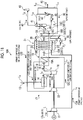
- FIG. 1A is a schematic view of a gas turbine cycle equipment related to Example 1.
- FIG. 1B is a schematic view illustrating an example of the temperature/pressure conditions of the gas turbine cycle equipment related to Example 1.
- the primary compressed air 12B which entrains the steam that has been subjected to heat exchange in the saturator 31 of the second heat exchange unit 19B, is introduced into the secondary air compressor 22, thereby producing high-pressure secondary compressed air (low temperature) 12C, then heat exchange of the high-pressure secondary compressed air (low temperature) 12C in the first heat exchange unit 19A is performed, thereby producing high-pressure secondary compressed air (high temperature) 12D, and then, the high-pressure secondary compressed air (high temperature) 12D is introduced into the combustor 14 as compressed air for combustion.
- reference sign 45 represents discharge water
- 46 represents a chimney
- G represents a power generator that is coupled to the power turbine 16 and generates power
- L 1 represents an air introduction line
- L 2 represents a primary compressed air supply line
- L 3 represents a secondary compressed air supply line
- L 4 represents a fuel supply line
- L 5 represents a combustion gas supply line
- L 6 represents a combustion flue gas discharge line
- L 7 represents a flue gas line
- L 8 represents a flue gas discharge line along which the flue gas 40 is to be discharged to the chimney 46
- L 12 represents a wastewater line.
- the gas turbine 17 includes the primary and secondary air compressors 21 and 22, the combustor 14, and the power turbine 16.
- the air 12a introduced from the outside is compressed in the primary and secondary air compressors 21 and 22, and the compressed air 12 made to have high temperature/high pressure is guided to the combustor 14 side.
- the high-temperature/high-pressure compressed air 12, and the fuel 13 are injected and combusted, and a high-temperature (for example, 1500°C) combustion gas 15 is generated.
- the combustion gas 15 is injected into the power turbine 16, and the heat energy of the high-temperature high-pressure combustion gas 15 is converted into rotational energy in the power turbine 16.
- the coaxial primary/secondary air compressors 21 and 22 are driven with this rotational energy, and the power generator G is driven with the rotational energy remaining after being used to drive this compressor, and generates power.
- the combustion flue gas 18 that has driven the power turbine 16 is guided to the exhaust heat recovery device 19 in order to recover the heat energy thereof.
- This exhaust heat recovery device 19 includes the first heat exchange unit 19A and the second heat exchange unit 19B.
- the secondary compressed air (a low temperature of 275°C and a pressure of 21 ata (2.1 MPa)) 12C is subjected to heat exchanged using the high-temperature (for example, 617°C) combustion flue gas 18 discharged from the power turbine 16.
- the primary compressed air (a temperature of 224°C and a pressure of 6 ata (0.6 MPa)) 12A is introduced into the saturator 31 and is subjected to heat exchange.
- the saturator 31 includes a supply water header 32 that introduces the supply water 30 condensed in the cooling tower 41 thereinto, a plurality of heat exchange tubes 33 that communicate with the supply water header 32 on one end 33a side and are arranged within the exhaust heat recovery device 19, a storage header 37 that communicates with the heat exchange tubes 33 on the other end 33b side, stores the supply water 30 within a storage part 34, and has an introducing part 36 that introduces the primary compressed air 12A into a space 35 on an upper side of the storage part 34, and a supply water circulation line L 20 along which the supply water 30 is circulated with a pump P 2 .
- FIGS. 4 and 5 are views illustrating an aspect in which supply water is supplied to each heat exchange tube 33 within the supply water header 32.
- a supply nozzle 39 provided in the supply water header 32 is used for the supply of the supply water 30, and the supply water 30 sprayed from the supply nozzle 39 is dropped while forming a water screen 30a in the shape of a wet wall along a wall surface 33d within the heat exchange tube 33.
- the primary compressed air 12A is passed from a lower side into a tube space 33c for the supply water 30 dropped and circulated by the water screen 30a along the wall surface 33d of each of the plurality of heat exchange tube 33. Then, when the primary compressed air 12A passes, the primary compressed air is subjected to heat exchange with the combustion flue gas 18A that abuts against an outer periphery of each heat exchange tube 33. In the case of this heat exchange, the steam 38 is generated while heating the supply water 30 that flows down, this generated steam 38 is entrained in the primary compressed air 12A subjected to heat exchange, and is created as the primary compressed air (water steam) 12B.
- the supply water 30 is injected by the supply nozzle 39 and IS made to flow into the heat exchange tube 33.
- the supply water 30 that has flowed into the heat exchange tube 33 is dropped while forming the water screen 30a in the shape of a wet wall along the wall surface 33d of the heat exchange tube 33, and is stored on the storage header 37 on the downstream side.
- the stored supply water 30 is again circulated through the supply water header 32 by the supply water circulation line L 20 via the pump P 2 .
- the wet wall-like water screen 30a that flows through the inside of the heat exchange tube 33 is indirectly heated by the heat of the combustion flue gas 18A from the outside, and the supply water 30 becomes the steam 38 by heat exchange, is entrained in the primary compressed air 12A, and becomes the primary compressed air (water steam) 12B.
- the second heat exchange unit 19B performs heat exchange using the combustion flue gas 18A that has contributed to the heat exchange in the first heat exchange unit 19A.
- the primary compressed air (water steam) 12B is introduced into the secondary air compressor 22, is subjected to second compression, and becomes the high-pressure (a pressure of 21 ata (2.1 MPa)) secondary compressed air (low temperature: 275°C) 12C.
- the secondary compressed air 12C is low (275°C) in temperature, is capable of being subjected to heat exchange with the high-temperature (for example, 617°C) combustion flue gas 18 in the first heat exchange unit 19A of the exhaust heat recovery device 19, and becomes the high-pressure secondary compressed air (a high temperature of 565°C) 12D.
- the primary compressed air (a temperature of 224°C) compressed by the primary air compressor is introduced into the same secondary air compressor as it is, and is introduced into the combustor as high-pressure (21 ata)/high-temperature (400°C) compressed air.
- a total amount of the low-pressure (a pressure of 6 ata) primary compressed air 12A, which has passed through the primary air compressor 21 is introduced into the second heat exchange unit 19B of the exhaust heat recovery device 19, is subjected to heat exchange with the combustion flue gas 18A after being subjected to heat exchange in the first heat exchange unit 19A, in the saturator 31.
- the supply water 30 is introduced so as to lower (275°C ⁇ 84°C) the temperature of the low-pressure (a pressure of 6 ata) primary compressed air 12A, is subjected to heat exchange with the exhaust heat of the combustion flue gas (a temperature of 336°C) 18A after being subjected to heat exchange in the first heat exchange unit 19A, and becomes the low-pressure primary compressed air (water steam) 12B of which the temperature has been raised (107°C).
- the primary compressed air (water steam) (107°C) 12B is further compressed by the secondary air compressor 22 next, and becomes the high-pressure (a pressure of 21 ata) secondary compressed air (low temperature: 275°C) 12C.
- this secondary compression the capacity of the compressor can be made small because the temperature falls unlike a case where compression is continuous as in the related art.
- the high-pressure secondary compressed air (low temperature: 275°C) 12C is introduced into the first heat exchange unit 19A of the exhaust heat recovery device 19, becomes the high-pressure secondary compressed air (high temperature: 565°C) 12D, and is introduced into the combustor 14.
- the amount of the steam 38 to be entrained is small in the case of the heat exchange of the primary compressed air 12A in the second heat exchange unit 19B, it is possible to raise combustion temperature in the combustor 14 to a high temperature of, for example, 1500°C.
- FIG. 6 is a relationship view between temperature and enthalpy in a temperature falling line of an combustion flue gas and in a rising line of supply water temperature and compressed air.
- the temperature of the combustion flue gas 18 falls gradually (the first heat exchange unit 19A (617°C ⁇ 336°C), the second heat exchange unit 19B (336°C ⁇ 120°C), and the third heat exchange unit 19C (120°C ⁇ 95°C)) in the first heat exchange unit 19A, the second heat exchange unit 19B, and the third heat exchange unit 19C.
- the supply water 30 rises from 40°C to 88°C in the third heat exchange unit 19C, and rises from 84°C to 107°C because the temperature of the primary compressed air 12A falls in the saturator 31.
- the secondary compressed air 12C rises from 275°C to 565°C in the first heat exchange unit 19A.
- gas turbine cycle efficiency reaches 66.76% (LHV base) depending on a relationship between input heat and exhaust loss. This made it possible to achieve a significant improvement of about 6.7% or more greater than 60% that is the gas turbine cycle efficiency of a related-art 1500°C class.
- the exhaust heat recovery device 19 of the present example when exhaust heat is recovered by performing heat exchange of the combustion flue gas 18, in the exhaust heat recovery device 19 of the present example, efficient heat exchange is performed in the first heat exchange unit 19A, the second heat exchange unit 19B, and the third heat exchange unit 19C, respectively.
- the third heat exchange unit 19C may be omitted as illustrated in the gas turbine cycle equipment 10B illustrated in FIG. 7 .
- FIG. 8 is a schematic view of the equipment for recovering CO 2 from flue gas related to Example 2.
- the equipment 50 for recovering CO 2 from flue gas related to the present example includes the gas turbine cycle equipment 10A of Example 1, and a CO 2 recovery unit 51 that recovers CO 2 in the flue gas 40 from which the moisture from the cooling tower 41 has been removed.
- the CO 2 recovery unit 51 includes a CO 2 absorption tower 53 that remove CO 2 in the flue gas 40 after cooling in the cooling tower 41, using an absorbing liquid 52, and an absorbing liquid regeneration tower 54 that regenerates the absorbing liquid 52.
- the CO 2 recovery unit 51 makes the amine absorbing liquid to absorb and remove CO 2 contained in the flue gas 40 within the CO 2 absorption tower 53, and discharges the removed CO 2 as a treated flue gas 55 from a top side of the CO 2 absorption tower 53.
- the absorbing liquid 52 that has absorbed CO 2 is regenerated by steam stripping using a reboiler 59, in the absorbing liquid regeneration tower 54, and forms closed-system circulation lines L 21 and L 22 to be again reused in the CO 2 absorption tower 53.
- the amine-based absorbing liquid is, for example, brought into opposed contact with the flue gas 40 so as to take CO 2 into the amine absorbing liquid.
- the gas 56 containing CO 2 removed by the steam stripping is discharged, moisture is removed by a gas-liquid separator, and CO 2 is recovered as gas.
Landscapes
- Engineering & Computer Science (AREA)
- Chemical & Material Sciences (AREA)
- Combustion & Propulsion (AREA)
- Mechanical Engineering (AREA)
- General Engineering & Computer Science (AREA)
- General Chemical & Material Sciences (AREA)
- Analytical Chemistry (AREA)
- Oil, Petroleum & Natural Gas (AREA)
- Chemical Kinetics & Catalysis (AREA)
- Life Sciences & Earth Sciences (AREA)
- Sustainable Development (AREA)
- Sustainable Energy (AREA)
- Physics & Mathematics (AREA)
- Thermal Sciences (AREA)
- Treating Waste Gases (AREA)
Claims (6)
- Gasturbinenkreislaufausrüstung (10), umfassend:eine Gasturbine (17) mit einer Brennkammer (14), die Kraftstoff (13) mit Druckluft (12) verbrennt, und eine Leistungsturbine (16), die durch Verbrennungsabgas (18) von der Brennkammer (14) angetrieben wird; undeine Abgaswärme-Rückgewinnungsvorrichtung (19), die Wärmeenergie aus dem Verbrennungsabgas (18), das die Leistungsturbine (16) angetrieben hat, rückgewinnt,wobei die Druckluft (12) Primärdruckluft (12A), die von einem Luft verdichtenden Primärluftverdichter (21) verdichtet wird, und Sekundärdruckluft (12C) umfasst, die von einem Sekundärluftverdichter (22) verdichtet wird, der die Primärdruckluft (12A) weiter verdichtet, wobei die Abgaswärme-Rückgewinnungsvorrichtung (19) umfasst:eine erste Wärmetauschereinheit (19A), die einen indirekten Wärmetausch zwischen dem Verbrennungsabgas (18) und der Sekundärdruckluft (12C) ausführt, undeine zweite Wärmetauschereinheit (19B) mit einem Sättiger (31), wobei die Einheit sich stromabwärts der ersten Wärmetauschereinheit (19A) befindet und so eingerichtet ist, dass sie einen indirekten Wärmetausch zwischen dem Verbrennungsabgas (18) nach dem ersten Wärmetausch, der Primärdruckluft (12A) und Speisewasser (30) in dem Sättiger (31) ausführt und Dampf in die Primärdruckluft (12A) mitnimmt,wobei der Sättiger (31) der zweiten Wärmetauschereinheit (19B) umfasst:einen Speisewassersammler (32), der das Speisewasser (30) in diese einbringt,eine Mehrzahl von Wärmetauschrohren (33), die mit dem Speisewassersammler (32) an einem Ende in Verbindung stehen und innerhalb der Abgaswärme-Rückgewinnungsvorrichtung (19) angeordnet sind,einen Speichersammler (34), der mit den Wärmetauschrohren (33) an dem anderen Ende in Verbindung steht, das Speisewasser (33) speichert und ein Einführteil (36) hat, welches die Primärdruckluft (12A) in einen Bereich (35) eines Speicherteils (34) einbringt, undeine Speisewasser-Zirkulationsleitung (L20), entlang welcher das Speisewasser (30) zirkuliert,wobei die Primärdruckluft (12A) durch Rohrbereiche (33c) für Speisewasser (30) hindurch geführt wird, das in Form einer nassen Wand entlang Innenwandflächen (33d) der Wärmetauschrohre (33) zirkuliert, wobei die Primärdruckluft (12A) einem Wärmetausch mit dem Verbrennungsabgas (18) unterzogen wird, das an Außenumfängen der Wärmetauschrohre (33) angrenzt, Dampf (38) erzeugt wird, während das Speisewasser (30) erwärmt wird und der erzeugte Dampf (38) in der Primärdruckluft (12A), die einem Wärmetausch unterzogen wird, mitgenommen wird,wobei die Primärdruckluft (12A), die den Dampf (38), der einem Wärmetausch in dem Sättiger (31) der zweiten Wärmetauschereinheit (19B) unterzogen wurde, mitnimmt, in den Sekundärluftverdichter (22) eingebracht wird, wodurch Sekundärdruckluft (12C) mit Hochdruck/Niedrigtemperatur erzeugt wird, dann wird ein Wärmetausch der Sekundärdruckluft (12C) mit Hochdruck/Niedrigtemperatur in der ersten Wärmetauschereinheit (19A) ausgeführt, wodurch Sekundärdruckluft (12D) mit Hochdruck/Hochtemperatur erzeugt wird, und dann wird die Sekundärdruckluft (12D) mit Hochdruck/Hochtemperatur in die Brennkammer eingeführt.
- Gasturbinenkreislaufausrüstung (10) nach Anspruch 1, weiterhin umfassend:einen Kühlturm (41), der das von der Abgaswärme-Rückgewinnungsvorrichtung (19) nach dem Wärmetausch abgegebene Verbrennungsabgas (18) kühlt; undeine Speisewasser-Zufuhrleitung (L11), entlang welcher kondensiertes Wasser (44) als Speisewasser (30) an die Speisewasser-Zirkulationsleitung (L20) zugeführt wird, entlang welcher das Speisewasser (30) durch den Sättiger (31) zirkuliert.
- Gasturbinenkreislaufausrüstung (10) nach Anspruch 1 oder 2, wobei die Abgaswärme-Rückgewinnungsvorrichtung (19) weiterhin eine dritte Wärmetauschereinheit (19C) umfasst, die einen indirekten Wärmeaustausch zwischen dem Verbrennungsabgas (18) nach dem Passieren durch die zweite Wärmetauschereinheit (19B) und dem Speisewasser (30) in der Speisewasser-Zufuhrleitung (L11) ausführt.
- Ausrüstung (50) zum Rückgewinnen von CO2 aus dem Verbrennungsabgas (18), umfassend:die Gasturbinenkreislaufausrüstung (10) nach einem der Ansprüche 1 bis 3; undeine CO2 Rückgewinnungseinheit (51), die CO2 in dem Verbrennungsabgas (18) von dem Kühlturm (41) rückgewinnt.
- Ausrüstung zum Rückgewinnen von CO2 aus dem Verbrennungsabgas (18) nach Anspruch 4,
wobei die CO2 Rückgewinnungseinheit (51) einen CO2 Absorptionsturm (53), der CO2 in dem Verbrennungsabgas (18) mit einer Absorptionsflüssigkeit absorbiert, und einen Absorptionsflüssigkeits-Regenerationsturm (54) umfasst, der die Absorptionsflüssigkeit, die CO2 absorbiert hat, regeneriert, und
die Absorptionsflüssigkeit zirkuliert und wiederverwendet wird. - Verfahren zum Rückgewinnen von Abgas aus Verbrennungsabgas (18), wobei das Verfahren umfasst:Verwenden der Gasturbinenkreislaufausrüstung (10) nach Anspruch 1, undUnterziehen des Verbrennungsabgases (18) von der Gasturbine (17) einem Wärmetausch mit unter Hochdruck stehender Sekundärdruckluft (12C) in der ersten Wärmetauschereinheit (19A) der Abgaswärme-Rückgewinnungsvorrichtung (19), Ausführen einer Wärmerückgewinnung von Primärdruckluft (12A) mit geringem Druck unter Verwendung des dem Wärmetausch unterzogenen Verbrennungsabgases (18) in der zweiten Wärmetauschereinheit (19B) mit dem Sättiger (31), Einbringen der Primärdruckluft (12B), die die Wärme in der zweiten Wärmetauschereinheit (19B) rückgewonnen hat, in den Sekundärluftverdichter (22), wodurch unter Hochdruck stehende Primärdruckluft (12C) erzeugt wird, dann Rückgewinnen der Wärme in der ersten Wärmetauschereinheit (19A), wodurch Sekundärdruckluft (12D) erzeugt wird und die Sekundärdruckluft (12D) in die Brennkammer (14) eingebracht wird, um Kraftstoff unter Verwendung der Sekundärdruckluft (12D) zu verbrennen.
Applications Claiming Priority (2)
| Application Number | Priority Date | Filing Date | Title |
|---|---|---|---|
| JP2014101758A JP6327941B2 (ja) | 2014-05-15 | 2014-05-15 | ガスタービンサイクル設備、排ガスのco2回収設備及び燃焼排ガスの排熱回収方法 |
| PCT/JP2015/062473 WO2015174246A1 (ja) | 2014-05-15 | 2015-04-24 | ガスタービンサイクル設備、排ガスのco2回収設備及び燃焼排ガスの排熱回収方法 |
Publications (3)
| Publication Number | Publication Date |
|---|---|
| EP3128151A1 EP3128151A1 (de) | 2017-02-08 |
| EP3128151A4 EP3128151A4 (de) | 2017-04-26 |
| EP3128151B1 true EP3128151B1 (de) | 2019-01-02 |
Family
ID=54479789
Family Applications (1)
| Application Number | Title | Priority Date | Filing Date |
|---|---|---|---|
| EP15792546.2A Active EP3128151B1 (de) | 2014-05-15 | 2015-04-24 | Gasturbinenkreislaufausrüstung, ausrüstung zur rückgewinnung von co2 aus abgas und verfahren zur rückgewinnung von abwärme aus verbrennungsabgasen |
Country Status (5)
| Country | Link |
|---|---|
| US (1) | US10480406B2 (de) |
| EP (1) | EP3128151B1 (de) |
| JP (1) | JP6327941B2 (de) |
| CA (1) | CA2947254C (de) |
| WO (1) | WO2015174246A1 (de) |
Families Citing this family (11)
| Publication number | Priority date | Publication date | Assignee | Title |
|---|---|---|---|---|
| GB2546723B (en) * | 2015-12-11 | 2021-06-02 | Hieta Tech Limited | Inverted brayton cycle heat engine |
| JP6796140B2 (ja) * | 2016-10-19 | 2020-12-02 | 三菱重工業株式会社 | 二酸化炭素回収システム、火力発電設備、及び、二酸化炭素回収方法 |
| US20180216532A1 (en) * | 2017-01-31 | 2018-08-02 | General Electric Company | System and method for treating exhaust gas |
| CZ307836B6 (cs) * | 2018-01-17 | 2019-06-12 | Vysoká Škola Báňská-Technická Univerzita Ostrava | Zařízení pro výrobu elektřiny s využitím akumulace médií |
| JP2019190359A (ja) * | 2018-04-24 | 2019-10-31 | 三菱重工エンジニアリング株式会社 | プラント及び燃焼排ガス処理方法 |
| CN111664438B (zh) * | 2019-03-07 | 2021-10-08 | 中石化广州工程有限公司 | 一种水帘式定期排污扩容器 |
| JP7412102B2 (ja) * | 2019-07-24 | 2024-01-12 | 三菱重工業株式会社 | ガスタービンプラント |
| US11326513B1 (en) * | 2020-10-30 | 2022-05-10 | Doosan Heavy Industries & Construction Co., Ltd. | Hybrid power generation equipment |
| DE102022115556A1 (de) * | 2022-06-22 | 2023-12-28 | MTU Aero Engines AG | Verfahren zum Betreiben einer Strömungsmaschine |
| CN115060070B (zh) * | 2022-06-23 | 2024-03-15 | 北新建材(陕西)有限公司 | 一种利用干燥机余热加热冷水的温度循环控制使用系统 |
| EP4310393A1 (de) * | 2022-07-20 | 2024-01-24 | TotalEnergies OneTech | Anlage zum produzieren von elektrizität oder mechanischer energie, die eine gasturbine mit kombiniertem zyklus und co2-abschluss- und wasserelektrolyseeinheiten umfasst |
Family Cites Families (20)
| Publication number | Priority date | Publication date | Assignee | Title |
|---|---|---|---|---|
| CA1213737A (en) | 1981-12-10 | 1986-11-12 | Hiromi Nakamura | Regenerative gas turbine cycle |
| JPS58101227A (ja) * | 1981-12-10 | 1983-06-16 | Mitsubishi Gas Chem Co Inc | ガスタ−ビンサイクル |
| DE4237665A1 (de) * | 1992-11-07 | 1994-05-11 | Asea Brown Boveri | Verfahren zum Betrieb einer Kombianlage |
| JP4299313B2 (ja) * | 1997-04-22 | 2009-07-22 | 株式会社日立製作所 | ガスタービン設備 |
| DE10001112A1 (de) * | 2000-01-13 | 2001-07-19 | Alstom Power Schweiz Ag Baden | Kühlluftkühler für eine Gasturbinenanlage sowie Verwendung eines solchen Kühlluftkühlers |
| US7096659B1 (en) * | 2000-01-21 | 2006-08-29 | Hitachi, Ltd. | Gas turbine electric power generation equipment and air humidifier |
| US6584776B2 (en) | 2000-03-20 | 2003-07-01 | Exxonmobil Chemical Patents Inc. | Method for generating power |
| JP2003049665A (ja) * | 2001-08-03 | 2003-02-21 | Mitsui Eng & Shipbuild Co Ltd | ガスタービンコージェネレーションシステム |
| JP2003083003A (ja) | 2001-09-13 | 2003-03-19 | Mitsubishi Heavy Ind Ltd | ガスタービン及びガスタービン複合発電プラントの運転方法 |
| SE0301585D0 (sv) * | 2003-05-30 | 2003-05-30 | Euroturbine Ab | Förfarande för drift av en gasturbingrupp |
| JP2006002622A (ja) * | 2004-06-16 | 2006-01-05 | Mitsui Eng & Shipbuild Co Ltd | ガスタービン用再生器 |
| EP1609958A1 (de) * | 2004-06-22 | 2005-12-28 | Siemens Aktiengesellschaft | Gasturbine mit einem Verdichter und einem Rekuperator |
| JP5039651B2 (ja) * | 2008-07-08 | 2012-10-03 | 三菱重工業株式会社 | 排ガス中の二酸化炭素回収システム |
| WO2011076973A1 (en) * | 2009-12-22 | 2011-06-30 | Reijo Alander | Arrangement in a gas turbine process |
| DE102010013729A1 (de) | 2010-03-31 | 2011-10-06 | Siemens Aktiengesellschaft | Verfahren und Vorrichtung zum Abtrennen von Kohlendioxid aus einem Abgas einer fossil befeuerten Kraftwerksanlage |
| JP2013540229A (ja) * | 2010-10-05 | 2013-10-31 | アルストム テクノロジー リミテッド | Co2捕捉を備えたコンバインドサイクル発電所及びこれを運転する方法 |
| JP5747309B2 (ja) * | 2011-07-29 | 2015-07-15 | 一般財団法人電力中央研究所 | Caesシステムおよびこれを有する発電プラント |
| JP5716922B2 (ja) | 2012-02-22 | 2015-05-13 | 三菱日立パワーシステムズ株式会社 | 排熱回収ボイラおよび複合発電設備 |
| JP5639609B2 (ja) * | 2012-03-01 | 2014-12-10 | 三菱日立パワーシステムズ株式会社 | 高湿分空気利用ガスタービンシステム |
| JP5555276B2 (ja) * | 2012-04-05 | 2014-07-23 | 川崎重工業株式会社 | ランキンサイクルエンジンを備えるガスタービンエンジン装置 |
-
2014
- 2014-05-15 JP JP2014101758A patent/JP6327941B2/ja active Active
-
2015
- 2015-04-24 US US15/307,183 patent/US10480406B2/en active Active
- 2015-04-24 EP EP15792546.2A patent/EP3128151B1/de active Active
- 2015-04-24 WO PCT/JP2015/062473 patent/WO2015174246A1/ja not_active Ceased
- 2015-04-24 CA CA2947254A patent/CA2947254C/en active Active
Non-Patent Citations (1)
| Title |
|---|
| None * |
Also Published As
| Publication number | Publication date |
|---|---|
| US20170114718A1 (en) | 2017-04-27 |
| JP6327941B2 (ja) | 2018-05-23 |
| EP3128151A4 (de) | 2017-04-26 |
| JP2015218634A (ja) | 2015-12-07 |
| CA2947254C (en) | 2018-10-23 |
| CA2947254A1 (en) | 2015-11-19 |
| US10480406B2 (en) | 2019-11-19 |
| EP3128151A1 (de) | 2017-02-08 |
| WO2015174246A1 (ja) | 2015-11-19 |
Similar Documents
| Publication | Publication Date | Title |
|---|---|---|
| EP3128151B1 (de) | Gasturbinenkreislaufausrüstung, ausrüstung zur rückgewinnung von co2 aus abgas und verfahren zur rückgewinnung von abwärme aus verbrennungsabgasen | |
| JP7112378B2 (ja) | 効率が向上した動力発生方法およびシステム | |
| RU2315186C2 (ru) | Тепловая электростанция с малым выделением загрязняющих веществ | |
| ES2794776T3 (es) | Sistemas y métodos para la producción de energía que utilizan ciclos de CO2 anidados | |
| CN102741508B (zh) | 带有co2捕获的发电装置和运行这样的发电装置的方法 | |
| US9416683B2 (en) | Carbon dioxide recovery method and carbon-dioxide-recovery-type steam power generation system | |
| RU2456060C2 (ru) | Регенерация поглотителя отбираемым сжатым верхним потоком для обеспечения тепла | |
| US8252091B2 (en) | CO2 recovery from IGCC power plants | |
| US8720203B2 (en) | Carbon dioxide recovery method and carbon-dioxide-recovery-type steam power generation system | |
| US10072531B2 (en) | Hybrid power generation system using supercritical CO2 cycle | |
| CN108136321A (zh) | 用于co2捕集的方法和设备 | |
| CN101892878B (zh) | 用于与整体气化联合循环装置一起使用的方法和系统 | |
| US20140208782A1 (en) | System and method for waste heat utilization in carbon dioxide capture systems in power plants | |
| EP2444599A2 (de) | Kohlendioxid-Wiederherstellungsverfahren und Kohlendioxid-Wiederherstellungs-Stromerzeugungssystem | |
| JP2013151937A (ja) | プロセス発電プラント用ガスタービンの高温部品を冷却するために外部流体を使用する方法 | |
| Hu et al. | A low energy consumption de-carbonization natural gas combined cycle power generation system based on LiBr/H2O absorption heat transformer | |
| Conversano et al. | Techno-economic assessment of novel vs. standard 5m piperazine CCS absorption processes for conventional and high-efficiency NGCC power plants | |
| CN114382562A (zh) | 分流再压缩纯氧燃烧循环系统 | |
| JPH09264158A (ja) | ガスタービンサイクル | |
| JP2012161750A (ja) | Co2回収方法およびco2回収装置 | |
| JP2020159264A (ja) | ガスタービン | |
| CN210768960U (zh) | 带捕碳装置的燃煤发电系统 | |
| RU2211343C1 (ru) | Способ утилизации тепла в парогазовой установке контактного типа и установка для его осуществления | |
| CN109812335A (zh) | 零碳排放的整体煤气化-蒸气联合循环发电工艺 | |
| Verhaeghe et al. | Absorption-Based Carbon Capture Energy Penalty Reduction for Micro Gas Turbine Application: Comparison of Performance Using Different Solvents and Process Configurations |
Legal Events
| Date | Code | Title | Description |
|---|---|---|---|
| STAA | Information on the status of an ep patent application or granted ep patent |
Free format text: STATUS: THE INTERNATIONAL PUBLICATION HAS BEEN MADE |
|
| PUAI | Public reference made under article 153(3) epc to a published international application that has entered the european phase |
Free format text: ORIGINAL CODE: 0009012 |
|
| STAA | Information on the status of an ep patent application or granted ep patent |
Free format text: STATUS: REQUEST FOR EXAMINATION WAS MADE |
|
| 17P | Request for examination filed |
Effective date: 20161020 |
|
| AK | Designated contracting states |
Kind code of ref document: A1 Designated state(s): AL AT BE BG CH CY CZ DE DK EE ES FI FR GB GR HR HU IE IS IT LI LT LU LV MC MK MT NL NO PL PT RO RS SE SI SK SM TR |
|
| AX | Request for extension of the european patent |
Extension state: BA ME |
|
| A4 | Supplementary search report drawn up and despatched |
Effective date: 20170329 |
|
| RIC1 | Information provided on ipc code assigned before grant |
Ipc: F02C 3/30 20060101AFI20170323BHEP Ipc: B01D 53/62 20060101ALI20170323BHEP Ipc: F01K 21/04 20060101ALI20170323BHEP Ipc: F02C 7/143 20060101ALI20170323BHEP Ipc: F02C 7/08 20060101ALI20170323BHEP |
|
| DAV | Request for validation of the european patent (deleted) | ||
| DAX | Request for extension of the european patent (deleted) | ||
| GRAP | Despatch of communication of intention to grant a patent |
Free format text: ORIGINAL CODE: EPIDOSNIGR1 |
|
| STAA | Information on the status of an ep patent application or granted ep patent |
Free format text: STATUS: GRANT OF PATENT IS INTENDED |
|
| INTG | Intention to grant announced |
Effective date: 20180724 |
|
| RAP1 | Party data changed (applicant data changed or rights of an application transferred) |
Owner name: MITSUBISHI HEAVY INDUSTRIES ENGINEERING, LTD. |
|
| GRAS | Grant fee paid |
Free format text: ORIGINAL CODE: EPIDOSNIGR3 |
|
| GRAA | (expected) grant |
Free format text: ORIGINAL CODE: 0009210 |
|
| STAA | Information on the status of an ep patent application or granted ep patent |
Free format text: STATUS: THE PATENT HAS BEEN GRANTED |
|
| AK | Designated contracting states |
Kind code of ref document: B1 Designated state(s): AL AT BE BG CH CY CZ DE DK EE ES FI FR GB GR HR HU IE IS IT LI LT LU LV MC MK MT NL NO PL PT RO RS SE SI SK SM TR |
|
| REG | Reference to a national code |
Ref country code: GB Ref legal event code: FG4D |
|
| REG | Reference to a national code |
Ref country code: CH Ref legal event code: EP Ref country code: AT Ref legal event code: REF Ref document number: 1084674 Country of ref document: AT Kind code of ref document: T Effective date: 20190115 |
|
| REG | Reference to a national code |
Ref country code: IE Ref legal event code: FG4D |
|
| REG | Reference to a national code |
Ref country code: DE Ref legal event code: R096 Ref document number: 602015022902 Country of ref document: DE |
|
| REG | Reference to a national code |
Ref country code: NL Ref legal event code: FP |
|
| REG | Reference to a national code |
Ref country code: NO Ref legal event code: T2 Effective date: 20190102 |
|
| REG | Reference to a national code |
Ref country code: LT Ref legal event code: MG4D |
|
| REG | Reference to a national code |
Ref country code: AT Ref legal event code: MK05 Ref document number: 1084674 Country of ref document: AT Kind code of ref document: T Effective date: 20190102 |
|
| PG25 | Lapsed in a contracting state [announced via postgrant information from national office to epo] |
Ref country code: FI Free format text: LAPSE BECAUSE OF FAILURE TO SUBMIT A TRANSLATION OF THE DESCRIPTION OR TO PAY THE FEE WITHIN THE PRESCRIBED TIME-LIMIT Effective date: 20190102 Ref country code: PT Free format text: LAPSE BECAUSE OF FAILURE TO SUBMIT A TRANSLATION OF THE DESCRIPTION OR TO PAY THE FEE WITHIN THE PRESCRIBED TIME-LIMIT Effective date: 20190502 Ref country code: SE Free format text: LAPSE BECAUSE OF FAILURE TO SUBMIT A TRANSLATION OF THE DESCRIPTION OR TO PAY THE FEE WITHIN THE PRESCRIBED TIME-LIMIT Effective date: 20190102 Ref country code: PL Free format text: LAPSE BECAUSE OF FAILURE TO SUBMIT A TRANSLATION OF THE DESCRIPTION OR TO PAY THE FEE WITHIN THE PRESCRIBED TIME-LIMIT Effective date: 20190102 Ref country code: LT Free format text: LAPSE BECAUSE OF FAILURE TO SUBMIT A TRANSLATION OF THE DESCRIPTION OR TO PAY THE FEE WITHIN THE PRESCRIBED TIME-LIMIT Effective date: 20190102 Ref country code: ES Free format text: LAPSE BECAUSE OF FAILURE TO SUBMIT A TRANSLATION OF THE DESCRIPTION OR TO PAY THE FEE WITHIN THE PRESCRIBED TIME-LIMIT Effective date: 20190102 |
|
| PG25 | Lapsed in a contracting state [announced via postgrant information from national office to epo] |
Ref country code: LV Free format text: LAPSE BECAUSE OF FAILURE TO SUBMIT A TRANSLATION OF THE DESCRIPTION OR TO PAY THE FEE WITHIN THE PRESCRIBED TIME-LIMIT Effective date: 20190102 Ref country code: HR Free format text: LAPSE BECAUSE OF FAILURE TO SUBMIT A TRANSLATION OF THE DESCRIPTION OR TO PAY THE FEE WITHIN THE PRESCRIBED TIME-LIMIT Effective date: 20190102 Ref country code: IS Free format text: LAPSE BECAUSE OF FAILURE TO SUBMIT A TRANSLATION OF THE DESCRIPTION OR TO PAY THE FEE WITHIN THE PRESCRIBED TIME-LIMIT Effective date: 20190502 Ref country code: GR Free format text: LAPSE BECAUSE OF FAILURE TO SUBMIT A TRANSLATION OF THE DESCRIPTION OR TO PAY THE FEE WITHIN THE PRESCRIBED TIME-LIMIT Effective date: 20190403 Ref country code: BG Free format text: LAPSE BECAUSE OF FAILURE TO SUBMIT A TRANSLATION OF THE DESCRIPTION OR TO PAY THE FEE WITHIN THE PRESCRIBED TIME-LIMIT Effective date: 20190402 Ref country code: RS Free format text: LAPSE BECAUSE OF FAILURE TO SUBMIT A TRANSLATION OF THE DESCRIPTION OR TO PAY THE FEE WITHIN THE PRESCRIBED TIME-LIMIT Effective date: 20190102 |
|
| REG | Reference to a national code |
Ref country code: DE Ref legal event code: R097 Ref document number: 602015022902 Country of ref document: DE |
|
| PG25 | Lapsed in a contracting state [announced via postgrant information from national office to epo] |
Ref country code: DK Free format text: LAPSE BECAUSE OF FAILURE TO SUBMIT A TRANSLATION OF THE DESCRIPTION OR TO PAY THE FEE WITHIN THE PRESCRIBED TIME-LIMIT Effective date: 20190102 Ref country code: AT Free format text: LAPSE BECAUSE OF FAILURE TO SUBMIT A TRANSLATION OF THE DESCRIPTION OR TO PAY THE FEE WITHIN THE PRESCRIBED TIME-LIMIT Effective date: 20190102 Ref country code: EE Free format text: LAPSE BECAUSE OF FAILURE TO SUBMIT A TRANSLATION OF THE DESCRIPTION OR TO PAY THE FEE WITHIN THE PRESCRIBED TIME-LIMIT Effective date: 20190102 Ref country code: RO Free format text: LAPSE BECAUSE OF FAILURE TO SUBMIT A TRANSLATION OF THE DESCRIPTION OR TO PAY THE FEE WITHIN THE PRESCRIBED TIME-LIMIT Effective date: 20190102 Ref country code: AL Free format text: LAPSE BECAUSE OF FAILURE TO SUBMIT A TRANSLATION OF THE DESCRIPTION OR TO PAY THE FEE WITHIN THE PRESCRIBED TIME-LIMIT Effective date: 20190102 Ref country code: CZ Free format text: LAPSE BECAUSE OF FAILURE TO SUBMIT A TRANSLATION OF THE DESCRIPTION OR TO PAY THE FEE WITHIN THE PRESCRIBED TIME-LIMIT Effective date: 20190102 Ref country code: SK Free format text: LAPSE BECAUSE OF FAILURE TO SUBMIT A TRANSLATION OF THE DESCRIPTION OR TO PAY THE FEE WITHIN THE PRESCRIBED TIME-LIMIT Effective date: 20190102 |
|
| PLBE | No opposition filed within time limit |
Free format text: ORIGINAL CODE: 0009261 |
|
| STAA | Information on the status of an ep patent application or granted ep patent |
Free format text: STATUS: NO OPPOSITION FILED WITHIN TIME LIMIT |
|
| PG25 | Lapsed in a contracting state [announced via postgrant information from national office to epo] |
Ref country code: SM Free format text: LAPSE BECAUSE OF FAILURE TO SUBMIT A TRANSLATION OF THE DESCRIPTION OR TO PAY THE FEE WITHIN THE PRESCRIBED TIME-LIMIT Effective date: 20190102 |
|
| REG | Reference to a national code |
Ref country code: CH Ref legal event code: PL |
|
| 26N | No opposition filed |
Effective date: 20191003 |
|
| REG | Reference to a national code |
Ref country code: BE Ref legal event code: MM Effective date: 20190430 |
|
| PG25 | Lapsed in a contracting state [announced via postgrant information from national office to epo] |
Ref country code: LU Free format text: LAPSE BECAUSE OF NON-PAYMENT OF DUE FEES Effective date: 20190424 Ref country code: MC Free format text: LAPSE BECAUSE OF FAILURE TO SUBMIT A TRANSLATION OF THE DESCRIPTION OR TO PAY THE FEE WITHIN THE PRESCRIBED TIME-LIMIT Effective date: 20190102 |
|
| PG25 | Lapsed in a contracting state [announced via postgrant information from national office to epo] |
Ref country code: LI Free format text: LAPSE BECAUSE OF NON-PAYMENT OF DUE FEES Effective date: 20190430 Ref country code: CH Free format text: LAPSE BECAUSE OF NON-PAYMENT OF DUE FEES Effective date: 20190430 |
|
| PG25 | Lapsed in a contracting state [announced via postgrant information from national office to epo] |
Ref country code: BE Free format text: LAPSE BECAUSE OF NON-PAYMENT OF DUE FEES Effective date: 20190430 Ref country code: FR Free format text: LAPSE BECAUSE OF NON-PAYMENT OF DUE FEES Effective date: 20190430 Ref country code: SI Free format text: LAPSE BECAUSE OF FAILURE TO SUBMIT A TRANSLATION OF THE DESCRIPTION OR TO PAY THE FEE WITHIN THE PRESCRIBED TIME-LIMIT Effective date: 20190102 |
|
| PG25 | Lapsed in a contracting state [announced via postgrant information from national office to epo] |
Ref country code: TR Free format text: LAPSE BECAUSE OF FAILURE TO SUBMIT A TRANSLATION OF THE DESCRIPTION OR TO PAY THE FEE WITHIN THE PRESCRIBED TIME-LIMIT Effective date: 20190102 |
|
| PG25 | Lapsed in a contracting state [announced via postgrant information from national office to epo] |
Ref country code: IE Free format text: LAPSE BECAUSE OF NON-PAYMENT OF DUE FEES Effective date: 20190424 |
|
| PG25 | Lapsed in a contracting state [announced via postgrant information from national office to epo] |
Ref country code: CY Free format text: LAPSE BECAUSE OF FAILURE TO SUBMIT A TRANSLATION OF THE DESCRIPTION OR TO PAY THE FEE WITHIN THE PRESCRIBED TIME-LIMIT Effective date: 20190102 |
|
| PG25 | Lapsed in a contracting state [announced via postgrant information from national office to epo] |
Ref country code: MT Free format text: LAPSE BECAUSE OF FAILURE TO SUBMIT A TRANSLATION OF THE DESCRIPTION OR TO PAY THE FEE WITHIN THE PRESCRIBED TIME-LIMIT Effective date: 20190102 Ref country code: HU Free format text: LAPSE BECAUSE OF FAILURE TO SUBMIT A TRANSLATION OF THE DESCRIPTION OR TO PAY THE FEE WITHIN THE PRESCRIBED TIME-LIMIT; INVALID AB INITIO Effective date: 20150424 |
|
| PG25 | Lapsed in a contracting state [announced via postgrant information from national office to epo] |
Ref country code: MK Free format text: LAPSE BECAUSE OF FAILURE TO SUBMIT A TRANSLATION OF THE DESCRIPTION OR TO PAY THE FEE WITHIN THE PRESCRIBED TIME-LIMIT Effective date: 20190102 |
|
| P01 | Opt-out of the competence of the unified patent court (upc) registered |
Effective date: 20230522 |
|
| REG | Reference to a national code |
Ref country code: DE Ref legal event code: R081 Ref document number: 602015022902 Country of ref document: DE Owner name: MITSUBISHI HEAVY INDUSTRIES, LTD., JP Free format text: FORMER OWNER: MITSUBISHI HEAVY INDUSTRIES ENGINEERING, LTD., YOKOHAMA-SHI, KANAGAWA, JP |
|
| REG | Reference to a national code |
Ref country code: DE Ref legal event code: R081 Ref document number: 602015022902 Country of ref document: DE Owner name: MITSUBISHI HEAVY INDUSTRIES, LTD., JP Free format text: FORMER OWNER: MHI ENGINEERING, LTD., YOKOHAMA-SHI, KANAGAWA, JP |
|
| REG | Reference to a national code |
Ref country code: NL Ref legal event code: PD Owner name: MITSUBISHI HEAVY INDUSTRIES, LTD.; JP Free format text: DETAILS ASSIGNMENT: CHANGE OF OWNER(S), ASSIGNMENT; FORMER OWNER NAME: MHI ENGINEERING, LTD. Effective date: 20231206 Ref country code: NL Ref legal event code: HC Owner name: MHI ENGINEERING, LTD.; JP Free format text: DETAILS ASSIGNMENT: CHANGE OF OWNER(S), CHANGE OF OWNER(S) NAME; FORMER OWNER NAME: MITSUBISHI HEAVY INDUSTRIES ENGINEERING, LTD. Effective date: 20231206 |
|
| REG | Reference to a national code |
Ref country code: GB Ref legal event code: 732E Free format text: REGISTERED BETWEEN 20240404 AND 20240410 |
|
| PGFP | Annual fee paid to national office [announced via postgrant information from national office to epo] |
Ref country code: DE Payment date: 20250305 Year of fee payment: 11 |
|
| PGFP | Annual fee paid to national office [announced via postgrant information from national office to epo] |
Ref country code: NO Payment date: 20250409 Year of fee payment: 11 |
|
| PGFP | Annual fee paid to national office [announced via postgrant information from national office to epo] |
Ref country code: GB Payment date: 20260313 Year of fee payment: 12 |
|
| PGFP | Annual fee paid to national office [announced via postgrant information from national office to epo] |
Ref country code: IT Payment date: 20260320 Year of fee payment: 12 |
|
| PGFP | Annual fee paid to national office [announced via postgrant information from national office to epo] |
Ref country code: NL Payment date: 20260317 Year of fee payment: 12 |