EP3128165B1 - Katalysatorkammer mit einem darin eingebetteten katalysatorbett für ein monopropellanten-triebwerk eines raketentriebwerks - Google Patents
Katalysatorkammer mit einem darin eingebetteten katalysatorbett für ein monopropellanten-triebwerk eines raketentriebwerks Download PDFInfo
- Publication number
- EP3128165B1 EP3128165B1 EP15002350.5A EP15002350A EP3128165B1 EP 3128165 B1 EP3128165 B1 EP 3128165B1 EP 15002350 A EP15002350 A EP 15002350A EP 3128165 B1 EP3128165 B1 EP 3128165B1
- Authority
- EP
- European Patent Office
- Prior art keywords
- catalyst chamber
- catalyst
- chamber
- wall
- inlet
- Prior art date
- Legal status (The legal status is an assumption and is not a legal conclusion. Google has not performed a legal analysis and makes no representation as to the accuracy of the status listed.)
- Active
Links
Images

Classifications
-
- F—MECHANICAL ENGINEERING; LIGHTING; HEATING; WEAPONS; BLASTING
- F02—COMBUSTION ENGINES; HOT-GAS OR COMBUSTION-PRODUCT ENGINE PLANTS
- F02K—JET-PROPULSION PLANTS
- F02K9/00—Rocket-engine plants, i.e. plants carrying both fuel and oxidant therefor; Control thereof
- F02K9/08—Rocket-engine plants, i.e. plants carrying both fuel and oxidant therefor; Control thereof using solid propellants
- F02K9/32—Constructional parts; Details not otherwise provided for
- F02K9/34—Casings; Combustion chambers; Liners thereof
-
- F—MECHANICAL ENGINEERING; LIGHTING; HEATING; WEAPONS; BLASTING
- F02—COMBUSTION ENGINES; HOT-GAS OR COMBUSTION-PRODUCT ENGINE PLANTS
- F02K—JET-PROPULSION PLANTS
- F02K9/00—Rocket-engine plants, i.e. plants carrying both fuel and oxidant therefor; Control thereof
- F02K9/42—Rocket-engine plants, i.e. plants carrying both fuel and oxidant therefor; Control thereof using liquid or gaseous propellants
- F02K9/60—Constructional parts; Details not otherwise provided for
- F02K9/68—Decomposition chambers
-
- F—MECHANICAL ENGINEERING; LIGHTING; HEATING; WEAPONS; BLASTING
- F05—INDEXING SCHEMES RELATING TO ENGINES OR PUMPS IN VARIOUS SUBCLASSES OF CLASSES F01-F04
- F05D—INDEXING SCHEME FOR ASPECTS RELATING TO NON-POSITIVE-DISPLACEMENT MACHINES OR ENGINES, GAS-TURBINES OR JET-PROPULSION PLANTS
- F05D2250/00—Geometry
- F05D2250/20—Three-dimensional
- F05D2250/25—Three-dimensional helical
Definitions
- the invention relates to a catalyst chamber with a catalyst bed embedded therein for a monopropellant thruster of a rocket engine.
- the invention further relates to a monopropellant thruster of a rocket engine.
- Monopropellant thrusters are used in the field of space technology, in both carrier rockets or in different orbital applications. They are manufactured according to the different tasks for a wide range of thrust classes.
- Such a monopropellant thruster consists essentially of a chamber in which fuel decomposition takes place in a catalyst chamber. In the catalyst chamber a catalyst bed is embedded therein for the fuel decomposition.
- the decomposition chamber typically consists of a cylindrical housing in which the catalyst chamber is mounted with individual grains or monolithic shape of catalytically active material as catalyst bed.
- the propellant typically a liquid propellant, the fuel is decomposed resulting in a generation of high temperature gases and thus a generation of thrust.
- JP H01 168332 A discloses an apparatus for reforming fuel, the apparatus comprising an inner cylinder disposed within an outer cylinder. Heating layers and reforming catalyst layers are divided by a plurality of helical plates and are alternately arranged adjacent to each other in a space defined between the inner and the outer cylinder. Raw materials to be reformed are provided to the catalyst layers by conduit means and reformed gas is discharged by further conduit means. Conduit means are connected to the heating layers so as to supply or discharge a heat medium of high temperature to or from the heating layers.
- the construction of the catalyst bed of a monopropellant thruster is such that the propellant and the resulting reaction products pass through the catalyst bed axially or radially through one or more stages of the catalyst bed.
- the design of a substantially cylindrical catalyst bed is dependent, among others, from:
- the length of the catalyst bed in the direction in which the propellant and/or resulting reaction products pass through the catalyst bed defines the total necessary space of the catalyst chamber. Furthermore, the absolute length of the catalyst bed defines the loads caused by vibration at a thermal barrier. Hence, it would be desirable to have the absolute length of the catalyst bed as short as possible.
- a catalyst chamber with a catalyst bed embedded therein for a monopropellant thruster of a rocket engine comprises an inlet having a first cross-sectional area through which a propellant can be introduced into the catalyst chamber. Furthermore, the catalyst chamber comprises an outlet having a second cross-sectional area through which the propellant and/or resulting reaction products can be introduced into a combustion chamber of the thruster wherein the outlet is connected to the inlet via a catalyst volume of the catalyst chamber and the catalyst bed, respectively.
- At least one helical wall member arranged within the catalyst chamber and dividing the catalyst volume into two or more segments is provided such that an effective length of the catalyst bed of each segment passed through by the propellant and/or its reaction products is larger than a geometrical length of the catalyst chamber which is defined between the inlet and the outlet along a direction of extension of the catalyst chamber.
- the catalyst chamber according to the invention enables the reduction of the geometrical length of the catalyst chamber while maintaining the effective length of the catalyst bed compared to a conventional catalyst chamber having no helical wall member. On the other hand, by maintaining the geometric length of the catalyst chamber compared to a conventional catalyst chamber, the effective length of the catalyst bed can be enlarged.
- the catalyst chamber has a cylindrical shape having a circular cross-section such that its bases lie in parallel planes. Each of the planes is arranged orthogonal to the direction of extension of the catalyst chamber, wherein the distance of the two planes corresponds to the geometrical length of the catalyst chamber.
- the cross-section of the bases of the catalyst chamber corresponds to a cross-section of the inlet and may correspond to a cross-section of the outlet of the catalyst chamber.
- the inlet and the outlet have a circular shape or cross-section as well.
- the inlet and the outlet may lie in the respective planes of the bases of the catalyst chamber but do not necessarily have to capture their whole area.
- the cross-section of the inlet and the outlet may differ from a circular shape.
- the shape of the inlet and the outlet is concentrically to the outer walls defining the catalyst chamber, i.e. having a circular shape or cross-section as well.
- the at least one helical wall member may be an insertion element. As such, the at least one helical wall member may be inserted in the catalyst chamber after provision of the latter. Alternatively or additionally the at least one helical wall member may be an integral element of the catalyst chamber. This may be realized by additive manufacturing processes, for example.
- the at least one helical wall member may be made from one piece.
- the at least one helical wall member may be composed from several pieces being put together in its axial and/or radial direction.
- One of the pieces might be an integral part of the catalyst chamber, while another part might be realized as insertion element.
- the catalyst chamber may comprise an inner wall being arranged concentrically to an outer wall defining the catalyst chamber.
- the inner wall has a circular shape like the outer wall defining the catalyst chamber.
- the inner wall may be adapted to receive a heating element for preheating the catalyst bed.
- the inner wall may comprise at least one further helical wall member arranged within the inner wall and dividing the volume of the inner wall into two or more further segments. The segments (between the inner and the outer wall) and the further segments (within the inner wall) are arranged to be passed through by the propellant and/or its reaction products in parallel.
- the inner wall, the optional further helical wall member, and the helical wall member may be made of one or more pieces. However, they may be made of several pieces put together during manufacturing of the catalyst chamber.
- the segments and/or the further segments are separated from each other. According to this embodiment it is not possible that a propellant passing through one segment flows through an adjacent, different segment. This means, the at least one helical wall does not contain any recesses enabling a connection between adjacent segments of the catalyst bed.
- the invention further provides a monopropellant thruster of a rocket engine which comprises a catalyst chamber according to the description above and below.
- Fig. 1 shows a schematic view of a monopropellant thruster 1 of a rocket engine in a cross-section.
- the thruster 1 comprises a combustion chamber 2, a nozzle 3 and a propellant inlet 4.
- a catalyst chamber 10 with a catalyst bed embedded therein is arranged in the combustion chamber 2 which is arranged inbetween the propellant inlet 4 and the nozzle 3, a catalyst chamber 10 with a catalyst bed embedded therein is arranged.
- the propellant floods into the catalyst chamber 10 at an inlet 11 and passes through the catalyst chamber 10 and the catalyst bed, respectively, in a longitudinal direction of the monopropellant thruster 1.
- the propellant will be decomposed within the catalyst chamber 10. Resulting reaction products and/or propellant leave the catalyst chamber 10 at outlet 12 and will be introduced into the nozzle 3.
- the catalyst chamber 10 has a geometrical length I extending in the longitudinal direction, i.e. parallel to a longitudinal axis, of the thruster 1.
- the catalyst bed of the catalyst chamber 10 is passed through by the propellant and/or resulting reaction products in a direction being parallel to the longitudinal direction of the thruster 1.
- the geometrical length I of the catalyst chamber 10 corresponds to the effective length of the catalyst bed passed through by the propellant and/or its reaction products.
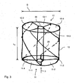
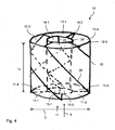
- Figs. 2 to 4 show different variations of a catalyst chamber 10 in which the geometrical length l 10 can be reduced while maintaining the effective length of the catalyst bed passed through by the propellant and/or its reaction products as compared to the arrangement in Fig. 1 .
- the catalyst chamber 10 has a substantially circular shape. It is to be noted that the axial direction of the catalyst chamber 10 and the direction of the propellant flow 5, in the figures, is seen from bottom to top. An outer wall 15 of the catalyst chamber 10 provides the already mentioned circular shape of the catalyst chamber 10.
- the inlet 11 has a circular cross-sectional area corresponding to the diameter of the catalyst chamber through which the propellant can be introduced into the catalyst chamber 10 and the catalyst bed, respectively.
- the outlet 12 has a circular cross-sectional area corresponding to the cross-sectional area of the inlet 11 and enables the introduction of the propellant and/or resulting reaction products into the combustion chamber of the thruster.
- a catalyst volume of the catalyst chamber 10 and the catalyst bed, respectively, is formed inbetween the inlet 11 and the outlet 12.
- the catalyst chamber 10 has a cylindrical shape having a circular cross-section. Its two bases correspond to the inlet 11 and the outlet 12 of the combustion chamber. The inlet 11 and the outlet 12 lie in parallel planes being orthogonal to the direction of extension of the catalyst chamber 10. The direction of extension corresponds to the longitudinal axis of the rocket engine. The distance of the two planes, i.e. the distance between the inlet 11 and the outlet 12, corresponds to the geometrical length l 10 of the catalyst chamber 10.
- a helical wall member 20 is arranged within the catalyst chamber 10 .
- the helical wall member 20 divides the catalyst volume into two segments.
- An inlet of a first segment is illustrated with 11-1, its outlet is denoted with 12-1.
- An inlet of the second segment is illustrated with 11-2 while its outlet is denoted with 12-2.
- Due to the helical shape of the wall member 20 the effective length of the catalyst bed of each of the two segments which is passed through by the propellant and/or its reaction products is larger than the geometrical length l 10 of the catalyst chamber 10.
- the geometrical length l 10 of the catalyst chamber 10 corresponds to the length I of Fig.
- the effective length of the catalyst bed can be enlarged.
- the effective length of the catalyst bed of the catalyst chamber 10 according to the invention corresponds to the length I of the catalyst chamber 10 of Fig. 1
- the geometrical length l 10 of the catalyst chamber 10 according to the invention can be reduced.
- the effective length of the catalyst bed can be controlled. This angle may be dependent from the diameter D and the cross-sectional area of the inlet 11 and the outlet 12.
- Fig. 3 shows an arrangement, in which the catalyst chamber 10 comprises an inner wall 30 being arranged concentrically to the outer wall 15 of the catalyst chamber 10. Between the inner and the outer walls 15, 30 by way of example four helical wall members are arranged dividing the catalyst volume into four segments. The inlets of the four segments are denoted with 11-1, 11-2, 11-3, 11-4, while the respective outlets are denoted with 12-1, 12-2, 12-3, 12-4.
- the inner wall 30 is adapted to receive a not shown heating element for preheating the catalyst bed in the four segments.
- the inner wall 30 comprises a further helical wall member 22 dividing the volume of the inner wall into two further segments instead of a heating element.
- An inlet of the first segment is denoted with 13-1, its outlet is denoted with 14-1.
- An inlet of the second further segment is denoted with 13-2, its outlet is denoted with 14-2.
- the four segments arranged between the inner and the outer wall 15, 30 and the two further segments arranged within the inner wall 30 are passed through by the propellant and/or its reaction products in parallel.
- the helical wall member and the further helical wall member 22, respectively may consist from one or more pieces. They can be provided as an insertion element or alternatively as an integral element of the catalyst chamber 10.
- the helical wall member 20 may be provided by additive manufacturing methods together with the outer wall 15, for example. In case of the arrangements illustrated in Figs. 3 and 4 , they may be provided as an integral element of the inner wall 30.
- the helical wall member 20, 22 can be arranged in one or more catalyst beds which are arranged in the direction of flow of the propellant one behind the other.
Landscapes
- Engineering & Computer Science (AREA)
- Chemical & Material Sciences (AREA)
- Combustion & Propulsion (AREA)
- Mechanical Engineering (AREA)
- General Engineering & Computer Science (AREA)
- Exhaust Gas After Treatment (AREA)
- Devices And Processes Conducted In The Presence Of Fluids And Solid Particles (AREA)
Claims (9)
- Katalysatorkammer (10) mit einem darin eingebetteten Katalysatorbett für ein Monopropellant-Triebwerk (1) eines Raketentriebwerks, die umfasst:- einen Einlass (11) mit einer ersten Querschnittsfläche, durch die ein Treibmittel in die Katalysatorkammer (10) zugeführt werden kann;- einen Auslass (12) mit einer zweiten Querschnittsfläche, durch den das Treibmittel und/oder resultierende Reaktionsprodukte in eine Brennkammer des Triebwerks (1) zugeführt werden können, wobei der Auslass (12) über ein Katalysatorvolumen der Katalysatorkammer (10) mit dem Einlass (11) verbunden ist;- mindestens ein helixförmiges Wandelement (20), das in der Katalysatorkammer (10) angeordnet ist und das Katalysatorvolumen in zwei oder mehr Segmente unterteilt, so dass eine effektive Länge des Katalysatorbetts eines jeden Segments, das von dem Treibstoff und/oder seinen Reaktionsprodukten durchströmt wird, größer ist als eine geometrische Länge (l10) der Katalysatorkammer (10), die zwischen dem Einlass (11) und dem Auslass (12) entlang einer Erstreckungsrichtung der Katalysatorkammer (10) definiert ist,dadurch gekennzeichnet, dass die Katalysatorkammer (10) eine zylindrische Form mit einem kreisförmigen Querschnitt aufweist, so dass ihre Grundflächen in parallelen Ebenen liegen, wobei jede der Ebenen orthogonal zur Erstreckungsrichtung der Katalysatorkammer (10) ist, wobei der Abstand der beiden Ebenen der geometrischen Länge (l10) der Katalysatorkammer (10) entspricht, und wobei der Querschnitt der Grundflächen der Katalysatorkammer (10) einem Querschnitt des Einlasses (11) und des Auslasses (12) der Katalysatorkammer (10) entspricht.
- Katalysatorkammer nach Anspruch 1, wobei das mindestens eine helixförmige Wandelement (20) ein Einsatzelement ist.
- Katalysatorkammer nach einem der vorhergehenden Ansprüche, wobei das mindestens eine helixförmige Wandelement (20) ein integriertes Element der Katalysatorkammer (10) ist.
- Katalysatorkammer nach einem der vorhergehenden Ansprüche, wobei die Katalysatorkammer (10) eine Innenwand (30) aufweist, die konzentrisch zu einer Außenwand (15) angeordnet ist.
- Katalysatorkammer nach Anspruch 4, wobei die Innenwand zur Aufnahme eines Heizelements zum Vorheizen des Katalysatorbetts eingerichtet ist.
- Katalysatorkammer nach Anspruch 4, wobei die Innenwand (30) mindestens ein weiteres helixförmiges Wandelement (22) aufweist, das in der Innenwand (30) angeordnet ist und das Volumen der Innenwand (30) in zwei oder mehr weitere Segmente unterteilt.
- Katalysatorkammer nach Anspruch 6, wobei die Segmente und die weiteren Segmente so angeordnet sind, dass sie von dem Treibmittel und/oder dessen Reaktionsprodukten parallel durchströmt werden.
- Katalysatorkammer nach einem der vorhergehenden Ansprüche, wobei die Segmente und/oder die weiteren Segmente voneinander getrennt sind.
- Monopropellant-Triebwerk (1) eines Raketentriebwerks, das eine Katalysatorkammer (10) nach einem der vorhergehenden Ansprüche umfasst.
Priority Applications (3)
| Application Number | Priority Date | Filing Date | Title |
|---|---|---|---|
| PL15002350T PL3128165T3 (pl) | 2015-08-06 | 2015-08-06 | Komora katalityczna z osadzonym w niej złożem katalizatora do silnika sterującego na jednoskładnikowy materiał pędny stanowiącego część silnika rakietowego |
| EP15002350.5A EP3128165B1 (de) | 2015-08-06 | 2015-08-06 | Katalysatorkammer mit einem darin eingebetteten katalysatorbett für ein monopropellanten-triebwerk eines raketentriebwerks |
| US15/225,438 US11248563B2 (en) | 2015-08-06 | 2016-08-01 | Catalyst chamber with a catalyst bed embedded therein for a monopropellant thruster of a rocket engine |
Applications Claiming Priority (1)
| Application Number | Priority Date | Filing Date | Title |
|---|---|---|---|
| EP15002350.5A EP3128165B1 (de) | 2015-08-06 | 2015-08-06 | Katalysatorkammer mit einem darin eingebetteten katalysatorbett für ein monopropellanten-triebwerk eines raketentriebwerks |
Publications (2)
| Publication Number | Publication Date |
|---|---|
| EP3128165A1 EP3128165A1 (de) | 2017-02-08 |
| EP3128165B1 true EP3128165B1 (de) | 2021-06-16 |
Family
ID=53785391
Family Applications (1)
| Application Number | Title | Priority Date | Filing Date |
|---|---|---|---|
| EP15002350.5A Active EP3128165B1 (de) | 2015-08-06 | 2015-08-06 | Katalysatorkammer mit einem darin eingebetteten katalysatorbett für ein monopropellanten-triebwerk eines raketentriebwerks |
Country Status (3)
| Country | Link |
|---|---|
| US (1) | US11248563B2 (de) |
| EP (1) | EP3128165B1 (de) |
| PL (1) | PL3128165T3 (de) |
Families Citing this family (2)
| Publication number | Priority date | Publication date | Assignee | Title |
|---|---|---|---|---|
| EP4450798A3 (de) * | 2019-11-22 | 2025-01-01 | Aerojet Rocketdyne, Inc. | Katalytisches triebwerk |
| DE102022000497A1 (de) | 2021-02-11 | 2022-08-11 | Mathias Herrmann | Reaktions- und Auslegungskonzept für Triebwerke zur katalytischen Steuerung / energetischen Auslösung (z.B. mit Metallzusätzen) der inneren Geschwindigkeit (Beschleunigung) und Austrittsgeschwindigkeit mit Beeinflussung von Temperatur sowie Druck für einen verbesserten Wirkungsgrad und Brennraumanpassung (Treiber-Konzept) |
Family Cites Families (6)
| Publication number | Priority date | Publication date | Assignee | Title |
|---|---|---|---|---|
| US3156544A (en) * | 1962-10-01 | 1964-11-10 | Allied Chem | Apparatus for making combustible gas |
| GB1346848A (en) * | 1971-05-12 | 1974-02-13 | Pioneer Research Inc | Catalytic decomposition of hydrazine |
| JPH01168332A (ja) * | 1987-12-25 | 1989-07-03 | Hitachi Ltd | 燃料改質装置 |
| CA2357960C (en) * | 2000-10-10 | 2007-01-30 | Tokyo Gas Co., Ltd. | Single-pipe cylinder type reformer |
| WO2002095207A1 (en) * | 2001-05-23 | 2002-11-28 | Svenska Rymdaktiebolaget | Reactor for decomposition of ammonium dinitramide-based liquid monopropellants and process for the decomposition |
| US8021447B2 (en) * | 2008-07-30 | 2011-09-20 | Idatech, Llc | Hydrogen-producing assemblies |
-
2015
- 2015-08-06 EP EP15002350.5A patent/EP3128165B1/de active Active
- 2015-08-06 PL PL15002350T patent/PL3128165T3/pl unknown
-
2016
- 2016-08-01 US US15/225,438 patent/US11248563B2/en active Active
Non-Patent Citations (1)
| Title |
|---|
| None * |
Also Published As
| Publication number | Publication date |
|---|---|
| PL3128165T3 (pl) | 2022-01-03 |
| EP3128165A1 (de) | 2017-02-08 |
| US11248563B2 (en) | 2022-02-15 |
| US20170037814A1 (en) | 2017-02-09 |
Similar Documents
| Publication | Publication Date | Title |
|---|---|---|
| US10654762B2 (en) | Additive manufactured combustible element with fuel and oxidizer | |
| US3023570A (en) | Rocket motor with controlled propellant charge | |
| EP3724482B1 (de) | Raketendüsenhalseinsatz | |
| EP3128165B1 (de) | Katalysatorkammer mit einem darin eingebetteten katalysatorbett für ein monopropellanten-triebwerk eines raketentriebwerks | |
| US20150292439A1 (en) | Injector element | |
| US3695041A (en) | Two-stage hydrazine rocket motor | |
| KR20160055169A (ko) | 전기적으로 점화되고 스로틀링되는 초전성 추진제 로켓 엔진 | |
| US20250137419A1 (en) | Injector with injector elements in circumferential rows that alternate between counter-clockwise and clockwise swirl | |
| US10920714B2 (en) | Stable hybrid rocket technology | |
| EP3129709A1 (de) | Brennkammer eines motors mit flüssigem treibmittel | |
| US9404441B2 (en) | Low velocity injector manifold for hypergolic rocket engine | |
| US20220120240A1 (en) | Vortex thruster system including catalyst bed with screen assembly | |
| US20060090453A1 (en) | Injection head for a liquid-propelled rocket engine | |
| KR101669166B1 (ko) | 다층 환형 고체 추진제 그레인과 세장비가 작은 점화기를 갖는 추력기 | |
| US10035489B2 (en) | Pyrotechnic charge and gas generator comprising such a charge | |
| JP2018511002A (ja) | 均一な噴射を確保しながら推進剤を排出することができる改良された推進剤噴射器 | |
| RU2324836C1 (ru) | Смесительная головка камеры жидкостного ракетного двигателя | |
| RU2554685C2 (ru) | Твердотопливный ракетный двигатель | |
| JP4183475B2 (ja) | ハイブリッドロケットエンジンの固体モータとその燃焼方法 | |
| CN116670445A (zh) | 用于加热流体流的电加热系统 | |
| EP2906809B1 (de) | Geschlitztes multidüsengitter mit integrierten kühlkanälen | |
| PL242632B1 (pl) | Komora spalania hybrydowego silnika rakietowego | |
| JP2008255786A (ja) | 推力装置 | |
| US3372547A (en) | Multiplug rocket engine | |
| US10519836B2 (en) | Catalyst structure |
Legal Events
| Date | Code | Title | Description |
|---|---|---|---|
| PUAI | Public reference made under article 153(3) epc to a published international application that has entered the european phase |
Free format text: ORIGINAL CODE: 0009012 |
|
| STAA | Information on the status of an ep patent application or granted ep patent |
Free format text: STATUS: THE APPLICATION HAS BEEN PUBLISHED |
|
| AK | Designated contracting states |
Kind code of ref document: A1 Designated state(s): AL AT BE BG CH CY CZ DE DK EE ES FI FR GB GR HR HU IE IS IT LI LT LU LV MC MK MT NL NO PL PT RO RS SE SI SK SM TR |
|
| AX | Request for extension of the european patent |
Extension state: BA ME |
|
| STAA | Information on the status of an ep patent application or granted ep patent |
Free format text: STATUS: REQUEST FOR EXAMINATION WAS MADE |
|
| 17P | Request for examination filed |
Effective date: 20170802 |
|
| RBV | Designated contracting states (corrected) |
Designated state(s): AL AT BE BG CH CY CZ DE DK EE ES FI FR GB GR HR HU IE IS IT LI LT LU LV MC MK MT NL NO PL PT RO RS SE SI SK SM TR |
|
| RAP1 | Party data changed (applicant data changed or rights of an application transferred) |
Owner name: ARIANEGROUP GMBH |
|
| STAA | Information on the status of an ep patent application or granted ep patent |
Free format text: STATUS: EXAMINATION IS IN PROGRESS |
|
| 17Q | First examination report despatched |
Effective date: 20190408 |
|
| GRAP | Despatch of communication of intention to grant a patent |
Free format text: ORIGINAL CODE: EPIDOSNIGR1 |
|
| STAA | Information on the status of an ep patent application or granted ep patent |
Free format text: STATUS: GRANT OF PATENT IS INTENDED |
|
| INTG | Intention to grant announced |
Effective date: 20210203 |
|
| GRAS | Grant fee paid |
Free format text: ORIGINAL CODE: EPIDOSNIGR3 |
|
| GRAA | (expected) grant |
Free format text: ORIGINAL CODE: 0009210 |
|
| STAA | Information on the status of an ep patent application or granted ep patent |
Free format text: STATUS: THE PATENT HAS BEEN GRANTED |
|
| AK | Designated contracting states |
Kind code of ref document: B1 Designated state(s): AL AT BE BG CH CY CZ DE DK EE ES FI FR GB GR HR HU IE IS IT LI LT LU LV MC MK MT NL NO PL PT RO RS SE SI SK SM TR |
|
| REG | Reference to a national code |
Ref country code: GB Ref legal event code: FG4D |
|
| REG | Reference to a national code |
Ref country code: CH Ref legal event code: EP |
|
| REG | Reference to a national code |
Ref country code: DE Ref legal event code: R096 Ref document number: 602015070378 Country of ref document: DE |
|
| REG | Reference to a national code |
Ref country code: AT Ref legal event code: REF Ref document number: 1402525 Country of ref document: AT Kind code of ref document: T Effective date: 20210715 |
|
| REG | Reference to a national code |
Ref country code: IE Ref legal event code: FG4D |
|
| REG | Reference to a national code |
Ref country code: NL Ref legal event code: FP |
|
| REG | Reference to a national code |
Ref country code: SE Ref legal event code: TRGR |
|
| REG | Reference to a national code |
Ref country code: LT Ref legal event code: MG9D |
|
| REG | Reference to a national code |
Ref country code: NO Ref legal event code: T2 Effective date: 20210616 |
|
| PG25 | Lapsed in a contracting state [announced via postgrant information from national office to epo] |
Ref country code: HR Free format text: LAPSE BECAUSE OF FAILURE TO SUBMIT A TRANSLATION OF THE DESCRIPTION OR TO PAY THE FEE WITHIN THE PRESCRIBED TIME-LIMIT Effective date: 20210616 Ref country code: LT Free format text: LAPSE BECAUSE OF FAILURE TO SUBMIT A TRANSLATION OF THE DESCRIPTION OR TO PAY THE FEE WITHIN THE PRESCRIBED TIME-LIMIT Effective date: 20210616 Ref country code: FI Free format text: LAPSE BECAUSE OF FAILURE TO SUBMIT A TRANSLATION OF THE DESCRIPTION OR TO PAY THE FEE WITHIN THE PRESCRIBED TIME-LIMIT Effective date: 20210616 Ref country code: BG Free format text: LAPSE BECAUSE OF FAILURE TO SUBMIT A TRANSLATION OF THE DESCRIPTION OR TO PAY THE FEE WITHIN THE PRESCRIBED TIME-LIMIT Effective date: 20210916 |
|
| REG | Reference to a national code |
Ref country code: AT Ref legal event code: MK05 Ref document number: 1402525 Country of ref document: AT Kind code of ref document: T Effective date: 20210616 |
|
| PG25 | Lapsed in a contracting state [announced via postgrant information from national office to epo] |
Ref country code: GR Free format text: LAPSE BECAUSE OF FAILURE TO SUBMIT A TRANSLATION OF THE DESCRIPTION OR TO PAY THE FEE WITHIN THE PRESCRIBED TIME-LIMIT Effective date: 20210917 Ref country code: LV Free format text: LAPSE BECAUSE OF FAILURE TO SUBMIT A TRANSLATION OF THE DESCRIPTION OR TO PAY THE FEE WITHIN THE PRESCRIBED TIME-LIMIT Effective date: 20210616 Ref country code: RS Free format text: LAPSE BECAUSE OF FAILURE TO SUBMIT A TRANSLATION OF THE DESCRIPTION OR TO PAY THE FEE WITHIN THE PRESCRIBED TIME-LIMIT Effective date: 20210616 |
|
| PG25 | Lapsed in a contracting state [announced via postgrant information from national office to epo] |
Ref country code: SK Free format text: LAPSE BECAUSE OF FAILURE TO SUBMIT A TRANSLATION OF THE DESCRIPTION OR TO PAY THE FEE WITHIN THE PRESCRIBED TIME-LIMIT Effective date: 20210616 Ref country code: SM Free format text: LAPSE BECAUSE OF FAILURE TO SUBMIT A TRANSLATION OF THE DESCRIPTION OR TO PAY THE FEE WITHIN THE PRESCRIBED TIME-LIMIT Effective date: 20210616 Ref country code: CZ Free format text: LAPSE BECAUSE OF FAILURE TO SUBMIT A TRANSLATION OF THE DESCRIPTION OR TO PAY THE FEE WITHIN THE PRESCRIBED TIME-LIMIT Effective date: 20210616 Ref country code: EE Free format text: LAPSE BECAUSE OF FAILURE TO SUBMIT A TRANSLATION OF THE DESCRIPTION OR TO PAY THE FEE WITHIN THE PRESCRIBED TIME-LIMIT Effective date: 20210616 Ref country code: AT Free format text: LAPSE BECAUSE OF FAILURE TO SUBMIT A TRANSLATION OF THE DESCRIPTION OR TO PAY THE FEE WITHIN THE PRESCRIBED TIME-LIMIT Effective date: 20210616 Ref country code: RO Free format text: LAPSE BECAUSE OF FAILURE TO SUBMIT A TRANSLATION OF THE DESCRIPTION OR TO PAY THE FEE WITHIN THE PRESCRIBED TIME-LIMIT Effective date: 20210616 Ref country code: PT Free format text: LAPSE BECAUSE OF FAILURE TO SUBMIT A TRANSLATION OF THE DESCRIPTION OR TO PAY THE FEE WITHIN THE PRESCRIBED TIME-LIMIT Effective date: 20211018 Ref country code: ES Free format text: LAPSE BECAUSE OF FAILURE TO SUBMIT A TRANSLATION OF THE DESCRIPTION OR TO PAY THE FEE WITHIN THE PRESCRIBED TIME-LIMIT Effective date: 20210616 |
|
| REG | Reference to a national code |
Ref country code: DE Ref legal event code: R097 Ref document number: 602015070378 Country of ref document: DE |
|
| REG | Reference to a national code |
Ref country code: CH Ref legal event code: PL |
|
| PG25 | Lapsed in a contracting state [announced via postgrant information from national office to epo] |
Ref country code: MC Free format text: LAPSE BECAUSE OF FAILURE TO SUBMIT A TRANSLATION OF THE DESCRIPTION OR TO PAY THE FEE WITHIN THE PRESCRIBED TIME-LIMIT Effective date: 20210616 |
|
| PLBE | No opposition filed within time limit |
Free format text: ORIGINAL CODE: 0009261 |
|
| REG | Reference to a national code |
Ref country code: BE Ref legal event code: MM Effective date: 20210831 |
|
| STAA | Information on the status of an ep patent application or granted ep patent |
Free format text: STATUS: NO OPPOSITION FILED WITHIN TIME LIMIT |
|
| PG25 | Lapsed in a contracting state [announced via postgrant information from national office to epo] |
Ref country code: LI Free format text: LAPSE BECAUSE OF NON-PAYMENT OF DUE FEES Effective date: 20210831 Ref country code: DK Free format text: LAPSE BECAUSE OF FAILURE TO SUBMIT A TRANSLATION OF THE DESCRIPTION OR TO PAY THE FEE WITHIN THE PRESCRIBED TIME-LIMIT Effective date: 20210616 Ref country code: CH Free format text: LAPSE BECAUSE OF NON-PAYMENT OF DUE FEES Effective date: 20210831 |
|
| 26N | No opposition filed |
Effective date: 20220317 |
|
| PG25 | Lapsed in a contracting state [announced via postgrant information from national office to epo] |
Ref country code: LU Free format text: LAPSE BECAUSE OF NON-PAYMENT OF DUE FEES Effective date: 20210806 Ref country code: AL Free format text: LAPSE BECAUSE OF FAILURE TO SUBMIT A TRANSLATION OF THE DESCRIPTION OR TO PAY THE FEE WITHIN THE PRESCRIBED TIME-LIMIT Effective date: 20210616 |
|
| PG25 | Lapsed in a contracting state [announced via postgrant information from national office to epo] |
Ref country code: IT Free format text: LAPSE BECAUSE OF FAILURE TO SUBMIT A TRANSLATION OF THE DESCRIPTION OR TO PAY THE FEE WITHIN THE PRESCRIBED TIME-LIMIT Effective date: 20210616 Ref country code: IE Free format text: LAPSE BECAUSE OF NON-PAYMENT OF DUE FEES Effective date: 20210806 Ref country code: BE Free format text: LAPSE BECAUSE OF NON-PAYMENT OF DUE FEES Effective date: 20210831 |
|
| PG25 | Lapsed in a contracting state [announced via postgrant information from national office to epo] |
Ref country code: HU Free format text: LAPSE BECAUSE OF FAILURE TO SUBMIT A TRANSLATION OF THE DESCRIPTION OR TO PAY THE FEE WITHIN THE PRESCRIBED TIME-LIMIT; INVALID AB INITIO Effective date: 20150806 |
|
| PG25 | Lapsed in a contracting state [announced via postgrant information from national office to epo] |
Ref country code: CY Free format text: LAPSE BECAUSE OF FAILURE TO SUBMIT A TRANSLATION OF THE DESCRIPTION OR TO PAY THE FEE WITHIN THE PRESCRIBED TIME-LIMIT Effective date: 20210616 |
|
| P01 | Opt-out of the competence of the unified patent court (upc) registered |
Effective date: 20230612 |
|
| PG25 | Lapsed in a contracting state [announced via postgrant information from national office to epo] |
Ref country code: MK Free format text: LAPSE BECAUSE OF FAILURE TO SUBMIT A TRANSLATION OF THE DESCRIPTION OR TO PAY THE FEE WITHIN THE PRESCRIBED TIME-LIMIT Effective date: 20210616 |
|
| PG25 | Lapsed in a contracting state [announced via postgrant information from national office to epo] |
Ref country code: TR Free format text: LAPSE BECAUSE OF FAILURE TO SUBMIT A TRANSLATION OF THE DESCRIPTION OR TO PAY THE FEE WITHIN THE PRESCRIBED TIME-LIMIT Effective date: 20210616 |
|
| PG25 | Lapsed in a contracting state [announced via postgrant information from national office to epo] |
Ref country code: MT Free format text: LAPSE BECAUSE OF FAILURE TO SUBMIT A TRANSLATION OF THE DESCRIPTION OR TO PAY THE FEE WITHIN THE PRESCRIBED TIME-LIMIT Effective date: 20210616 |
|
| PGFP | Annual fee paid to national office [announced via postgrant information from national office to epo] |
Ref country code: NL Payment date: 20250821 Year of fee payment: 11 |
|
| PGFP | Annual fee paid to national office [announced via postgrant information from national office to epo] |
Ref country code: DE Payment date: 20250820 Year of fee payment: 11 |
|
| PGFP | Annual fee paid to national office [announced via postgrant information from national office to epo] |
Ref country code: NO Payment date: 20250826 Year of fee payment: 11 |
|
| PGFP | Annual fee paid to national office [announced via postgrant information from national office to epo] |
Ref country code: PL Payment date: 20250725 Year of fee payment: 11 |
|
| PGFP | Annual fee paid to national office [announced via postgrant information from national office to epo] |
Ref country code: GB Payment date: 20250820 Year of fee payment: 11 |
|
| PGFP | Annual fee paid to national office [announced via postgrant information from national office to epo] |
Ref country code: FR Payment date: 20250829 Year of fee payment: 11 |
|
| PGFP | Annual fee paid to national office [announced via postgrant information from national office to epo] |
Ref country code: SE Payment date: 20250820 Year of fee payment: 11 |