EP3128181B1 - Verdichterrad für einen abgasturbolader - Google Patents
Verdichterrad für einen abgasturbolader Download PDFInfo
- Publication number
- EP3128181B1 EP3128181B1 EP16181125.2A EP16181125A EP3128181B1 EP 3128181 B1 EP3128181 B1 EP 3128181B1 EP 16181125 A EP16181125 A EP 16181125A EP 3128181 B1 EP3128181 B1 EP 3128181B1
- Authority
- EP
- European Patent Office
- Prior art keywords
- compressor wheel
- exhaust gas
- gas turbocharger
- base
- hub
- Prior art date
- Legal status (The legal status is an assumption and is not a legal conclusion. Google has not performed a legal analysis and makes no representation as to the accuracy of the status listed.)
- Active
Links
Images

Classifications
-
- F—MECHANICAL ENGINEERING; LIGHTING; HEATING; WEAPONS; BLASTING
- F04—POSITIVE - DISPLACEMENT MACHINES FOR LIQUIDS; PUMPS FOR LIQUIDS OR ELASTIC FLUIDS
- F04D—NON-POSITIVE-DISPLACEMENT PUMPS
- F04D29/00—Details, component parts, or accessories
- F04D29/26—Rotors specially for elastic fluids
- F04D29/28—Rotors specially for elastic fluids for centrifugal or helico-centrifugal pumps for radial-flow or helico-centrifugal pumps
- F04D29/284—Rotors specially for elastic fluids for centrifugal or helico-centrifugal pumps for radial-flow or helico-centrifugal pumps for compressors
-
- F—MECHANICAL ENGINEERING; LIGHTING; HEATING; WEAPONS; BLASTING
- F01—MACHINES OR ENGINES IN GENERAL; ENGINE PLANTS IN GENERAL; STEAM ENGINES
- F01D—NON-POSITIVE DISPLACEMENT MACHINES OR ENGINES, e.g. STEAM TURBINES
- F01D5/00—Blades; Blade-carrying members; Heating, heat-insulating, cooling or antivibration means on the blades or the members
- F01D5/02—Blade-carrying members, e.g. rotors
- F01D5/04—Blade-carrying members, e.g. rotors for radial-flow machines or engines
-
- F—MECHANICAL ENGINEERING; LIGHTING; HEATING; WEAPONS; BLASTING
- F01—MACHINES OR ENGINES IN GENERAL; ENGINE PLANTS IN GENERAL; STEAM ENGINES
- F01D—NON-POSITIVE DISPLACEMENT MACHINES OR ENGINES, e.g. STEAM TURBINES
- F01D5/00—Blades; Blade-carrying members; Heating, heat-insulating, cooling or antivibration means on the blades or the members
- F01D5/12—Blades
- F01D5/14—Form or construction
- F01D5/141—Shape, i.e. outer, aerodynamic form
-
- F—MECHANICAL ENGINEERING; LIGHTING; HEATING; WEAPONS; BLASTING
- F05—INDEXING SCHEMES RELATING TO ENGINES OR PUMPS IN VARIOUS SUBCLASSES OF CLASSES F01-F04
- F05D—INDEXING SCHEME FOR ASPECTS RELATING TO NON-POSITIVE-DISPLACEMENT MACHINES OR ENGINES, GAS-TURBINES OR JET-PROPULSION PLANTS
- F05D2220/00—Application
- F05D2220/40—Application in turbochargers
-
- F—MECHANICAL ENGINEERING; LIGHTING; HEATING; WEAPONS; BLASTING
- F05—INDEXING SCHEMES RELATING TO ENGINES OR PUMPS IN VARIOUS SUBCLASSES OF CLASSES F01-F04
- F05D—INDEXING SCHEME FOR ASPECTS RELATING TO NON-POSITIVE-DISPLACEMENT MACHINES OR ENGINES, GAS-TURBINES OR JET-PROPULSION PLANTS
- F05D2240/00—Components
- F05D2240/80—Platforms for stationary or moving blades
-
- F—MECHANICAL ENGINEERING; LIGHTING; HEATING; WEAPONS; BLASTING
- F05—INDEXING SCHEMES RELATING TO ENGINES OR PUMPS IN VARIOUS SUBCLASSES OF CLASSES F01-F04
- F05D—INDEXING SCHEME FOR ASPECTS RELATING TO NON-POSITIVE-DISPLACEMENT MACHINES OR ENGINES, GAS-TURBINES OR JET-PROPULSION PLANTS
- F05D2250/00—Geometry
- F05D2250/10—Two-dimensional
- F05D2250/18—Two-dimensional patterned
-
- F—MECHANICAL ENGINEERING; LIGHTING; HEATING; WEAPONS; BLASTING
- F05—INDEXING SCHEMES RELATING TO ENGINES OR PUMPS IN VARIOUS SUBCLASSES OF CLASSES F01-F04
- F05D—INDEXING SCHEME FOR ASPECTS RELATING TO NON-POSITIVE-DISPLACEMENT MACHINES OR ENGINES, GAS-TURBINES OR JET-PROPULSION PLANTS
- F05D2250/00—Geometry
- F05D2250/10—Two-dimensional
- F05D2250/18—Two-dimensional patterned
- F05D2250/183—Two-dimensional patterned zigzag
-
- F—MECHANICAL ENGINEERING; LIGHTING; HEATING; WEAPONS; BLASTING
- F05—INDEXING SCHEMES RELATING TO ENGINES OR PUMPS IN VARIOUS SUBCLASSES OF CLASSES F01-F04
- F05D—INDEXING SCHEME FOR ASPECTS RELATING TO NON-POSITIVE-DISPLACEMENT MACHINES OR ENGINES, GAS-TURBINES OR JET-PROPULSION PLANTS
- F05D2250/00—Geometry
- F05D2250/10—Two-dimensional
- F05D2250/18—Two-dimensional patterned
- F05D2250/184—Two-dimensional patterned sinusoidal
-
- F—MECHANICAL ENGINEERING; LIGHTING; HEATING; WEAPONS; BLASTING
- F05—INDEXING SCHEMES RELATING TO ENGINES OR PUMPS IN VARIOUS SUBCLASSES OF CLASSES F01-F04
- F05D—INDEXING SCHEME FOR ASPECTS RELATING TO NON-POSITIVE-DISPLACEMENT MACHINES OR ENGINES, GAS-TURBINES OR JET-PROPULSION PLANTS
- F05D2250/00—Geometry
- F05D2250/60—Structure; Surface texture
- F05D2250/61—Structure; Surface texture corrugated
- F05D2250/611—Structure; Surface texture corrugated undulated
-
- F—MECHANICAL ENGINEERING; LIGHTING; HEATING; WEAPONS; BLASTING
- F05—INDEXING SCHEMES RELATING TO ENGINES OR PUMPS IN VARIOUS SUBCLASSES OF CLASSES F01-F04
- F05D—INDEXING SCHEME FOR ASPECTS RELATING TO NON-POSITIVE-DISPLACEMENT MACHINES OR ENGINES, GAS-TURBINES OR JET-PROPULSION PLANTS
- F05D2250/00—Geometry
- F05D2250/70—Shape
- F05D2250/73—Shape asymmetric
Definitions
- the present invention relates to a compressor wheel for an exhaust gas turbocharger with a hub body and arranged thereon blades according to the preamble of claim 1.
- the invention also relates to an exhaust gas turbocharger with such a compressor wheel.
- a compressor wheel for an exhaust gas turbocharger with a hub base body and blade leaves arranged thereon is known, wherein the hub base body is designed as a polygon with a number of segments tilted relative to one another with a number of blade leaves.
- a compressor wheel for an exhaust gas turbocharger is known, with a hub body and arranged thereon blade leaves.
- compressor wheels consist of a hub base body and the blade blades arranged thereon
- modern compressor wheels usually having a backward curved configuration for thermodynamic reasons Compressor wheel outlet are equipped.
- This backward curvature leads under the influence of centrifugal force on a suction side in the connection region of the blades to the hub body to high tensile stresses, which reduce life expectancy.
- a higher speed and / or an even stronger reverse curvature are / is only possible to a limited extent for reasons of service life.
- the hub base bodies commonly used today are designed as round solid rotary body, this simple geometry is not ideal in terms of the particular occurring in a transition between the airfoil and the hub body load.
- this can be remedied only partially, since the highest load often does not occur in the transition itself, but in the hub body at the outlet of the transition.
- the present invention therefore deals with the problem of designing a compressor wheel in such a way that, on the one hand, it is weight-optimized and, on the other hand, it is designed to be optimized in terms of receiving possible loads.
- the present invention is based on the general idea of changing a hub body of a compressor wheel for an exhaust-gas turbocharger, which has hitherto been designed as a round rotary body, with respect to its shape in such a way that, in particular, critical load ranges, for example in a transition between the hub body and blades arranged thereon, are effectively relieved can, without the compressor wheel itself significantly more massive and thus formed heavier would have to be.
- the hub body is designed as a polygon with a number of blades corresponding number of segments tilted towards each other.
- the hub base body is changed in particular in the region of the transition to an airfoil so that it is better able to absorb the stresses occurring there, in particular tensile stresses due to a backward curvature of the individual airfoils, which not only increases the performance but also the life of such a compressor wheel can be.
- the individual segments have a radially outer surface that is straight in cross-section.
- the hub base body is thus designed as a polygon with a number of segments corresponding to the number of individual airfoils, wherein these segments each have a straight base surface and merge into one another like a sawtooth radially on the outside.
- a transition from a segment to an associated airfoil is rounded.
- the rounded transition is formed by a material addition to the base surface of the respective segment.
- a slight accumulation of material is provided in each case, which in order to take over there occurring elevated stresses is sufficient, however, which only represents a local material order compared to a fully reinforced hub body and thus makes the compressor according to the invention much easier.
- the hub body has a base facing the blades and wavy in the circumferential direction base, wherein a number of waves corresponds to a number of blades.
- a transition from the base into an associated airfoil is arranged in the region of a wave crest.
- said transition is formed in the base, for example, by a tangent to a wave slope.
- the hub body has a ripple in the circumferential direction on.
- a number of waves on the back of the hub body may correspond to a number of blades on the opposite front.
- the base surface or the hub base body can be stiffened by the wavy shape and at the same time can be made material-optimized with regard to the stresses occurring. Due to the wavy back of the hub base body locally occurring stresses, which usually occur under the blades on Rabine be reduced. The advantage of a wavy wheel back is the local material application at heavily loaded areas. This allows a mass-effective reduction of stress without unnecessary weight gain.
- the present invention is further based on the general idea of equipping an exhaust gas turbocharger with such a previously mentioned compressor wheel, wherein a significantly improved response of the exhaust gas turbocharger can be achieved by the compressor wheel according to the invention, which is significantly lighter due to the low local material application than previously fully thickened compressor wheels can.
- the life of the entire exhaust gas turbocharger can be extended because of the extension of the life of the compressor wheel no bursting thereof and thus damage to a compressor housing must be feared.
- the wave crests run radially inward and / or radially outward and go in alignment in the base, so no wave crests are present at a Ver emphasizerradeintritt and a Ver emphasizerradaustritt.
- waves or wave crests are arranged exclusively at those points where it also require the occurring loads. In this way, a load-optimized and at the same time weight-optimized compressor wheel can be created.
- thermodynamic disadvantages can be avoided.
- a compressor wheel 1 for an exhaust gas turbocharger 2 has a hub base body 3 and airfoils 4 arranged thereon.
- Fig. 1 only the hub body 3, but not the associated blades 4 are shown.
- a non-inventive embodiment is in the Fig. 3 to 5 shown.
- the hub body 3 according to the invention as a polygon with a number of the number of blades 4 corresponding number of mutually tilted segments 5 formed.
- the individual segments 5 (compare also the FIG. 2 ) preferably have at least radially outside a cross-sectionally straight base surface 6, which may vary depending on the requirements of the hub body 3 and the respective blade 4 and also tilted to each other.
- the transition 7 from a segment 5 into an associated airfoil 4 is preferably rounded, wherein the fillet or the rounded transition 7 is formed by a material addition 8, that is to say an additional material application, to the base surface 6 of the respective segment 5.
- the hub body 3 according to the invention and thus also the compressor wheel 1 according to the invention has the great advantage that this is only locally reinforced in the area in which the during operation of the exhaust gas turbocharger 2 occurring voltages are highest. By rounding out about it In addition, a notch-free transition both in the base 6 of the segment 5 and in the associated airfoil 4 are achieved, whereby voltage peaks can be avoided.
- the hub base body 3 here has a base plate 6 facing the blades and wavy in the circumferential direction, wherein a number of individual waves 10 corresponds to a number of blades 4.
- a back of the base 6 and the hub body 3 is formed wavy, the waves 10 of the back 9 and the base 6 are parallel.
- the back 9 without such waves that is just be formed, in this context, the back 9 on the hub body 3 of the compressor wheel 1 according to the Fig. 1 and 2 straight or can be formed with waves 10.
- a transition 7 from the base 6 into an associated airfoil 4 is preferably arranged in the region of a wave crest 11 or at least slightly adjacent thereto.
- a transition 7 between the wavy base 6 and the associated airfoil 4 is rounded, such as this according to the Fig. 3 is shown with a broken drawn line, wherein such a rounded transition 7 passes through an applied to a wave slope 12 tangent in the base 6.
- a tangential transition into the associated airfoil 4 can be achieved.
- the radial position of the wave peaks 11 can be calculated in relation to the compressor wheel size (compressor wheel radius) from the quotient "radius VR / position It has been found that the wave crest 11 is between 1.1 and 2.2 relative to the radius R VR of the compressor wheel 1. For a ratio of a radius R VR of the compressor wheel 1 to a maximum radial extent R WB of wave crest 11 is therefore valid 1.1 ⁇ R VR / R WB . ⁇ 2.2 ,
- the thickening, in particular material additions 8, of the wave crests 11 is thus present only in the intermediate region between two adjacent blade leaves 4.
- the course looks different. For all gradients, however, it is the same that they are not rotationally symmetrical and go back to the original, rotationally symmetrical hub profile both in the direction of the compressor wheel step 13 and in the direction of the compressor wheel outlet 14. As a result, thermodynamic disadvantages can be avoided.
Landscapes
- Engineering & Computer Science (AREA)
- Mechanical Engineering (AREA)
- General Engineering & Computer Science (AREA)
- Physics & Mathematics (AREA)
- Fluid Mechanics (AREA)
- Supercharger (AREA)
- Structures Of Non-Positive Displacement Pumps (AREA)
- Turbine Rotor Nozzle Sealing (AREA)
Description
- Die vorliegende Erfindung betrifft ein Verdichterrad für einen Abgasturbolader mit einem Nabengrundkörper und daran angeordneten Schaufelblättern gemäß dem Oberbegriff des Anspruchs 1. Die Erfindung betrifft außerdem einen Abgasturbolader mit einem solchen Verdichterrad.
- Aus der
US 8,721,287 B2 ist ein gattungsgemäßes Verdichterrad für einen Abgasturbolader mit einem Nabengrundkörper sowie daran angeordneten Schaufelblättern bekannt. Um dabei eine Belastung, insbesondere in einem Anbindungsbereich der Schaufelblätter an den Nabengrundkörper, reduzieren zu können, ist ein Übergang zwischen dem Nabengrundkörper und den Schaufelblättern in der Art einer Ellipse ausgerundet. - Aus der
WO 2014/015959 A1 ist ein Verdichterrad für einen Abgasturbolader mit einem Nabengrundkörper und daran angeordneten Schaufelblättern bekannt, wobei der Nabengrundkörper als Vieleck mit einer Anzahl der Schaufelblätter entsprechenden Anzahl an zueinander gekippten Segmenten ausgebildet ist. - Aus der
JP 2008-163760 A FR 1 002 707 A - Aus der
US 2012/0269636 A1 und derUS 5,215,439 A sind weitere Verdichterräder bekannt. - Generell bestehen Verdichterräder aus einem Nabengrundkörper sowie den daran angeordneten Schaufelblättern, wobei moderne Verdichterräder aus thermodynamischen Gründen üblicherweise mit einem rückwärts gekrümmten Verdichterradaustritt ausgestattet sind. Diese Rückwärtskrümmung führt unter Einfluss der Fliehkraft auf einer Saugseite im Anbindungsbereich der Schaufelblätter zum Nabengrundkörper zu hohen Zugspannungen, welche die Lebenserwartung reduzieren. Eine höhere Drehzahl und/oder eine noch stärkere Rückwärtskrümmung sind/ist aus Gründen der Lebensdauer jedoch nur eingeschränkt möglich. Darüber hinaus sind die heute üblicherweise eingesetzten Nabengrundkörper als durchgehend runde Drehkörper ausgestaltet, wobei diese einfache Geometrie hinsichtlich der besonders in einem Übergang zwischen dem Schaufelblatt und dem Nabengrundkörper auftretenden Belastung nicht ideal ist. Auch durch eine Vergrößerung eines Radius im Übergang zwischen dem Schaufelblatt und dem Nabengrundkörper, kann hierbei nur bedingt Abhilfe geschaffen werden, da die höchste Belastung oft nicht im Übergang selbst, sondern im Nabengrundkörper am Auslauf des Übergangs auftritt.
- Die vorliegende Erfindung beschäftigt sich daher mit dem Problem, ein Verdichterrad derart auszubilden, dass dieses zum einen gewichtsoptimiert und zum anderen optimiert hinsichtlich der Aufnahme möglicher Belastungen ausgebildet ist.
- Dieses Problem wird erfindungsgemäß durch den Gegenstand des unabhängigen Anspruchs 1 gelöst. Vorteilhafte Ausführungsformen sind Gegenstand der abhängigen Ansprüche.
- Die vorliegende Erfindung beruht auf dem allgemeinen Gedanken, einen bislang als runden Drehkörper ausgebildeten Nabengrundkörper eines Verdichterrades für einen Abgasturbolader nunmehr hinsichtlich seiner Gestalt derart zu verändern, dass insbesondere bislang kritische Belastungsbereiche, beispielsweise in einem Übergang zwischen dem Nabengrundkörper und daran angeordneten Schaufelblättern, wirkungsvoll entlastet werden können, ohne dass das Verdichterrad an sich deutlich massiver und damit schwerer ausgebildet werden müsste. Erfindungsgemäß ist dabei der Nabengrundkörper als Vieleck mit einer Anzahl der Schaufelblätter entsprechenden Anzahl an zueinander gekippten Segmenten ausgebildet. Dabei ist der Nabengrundkörper insbesondere im Bereich des Übergangs zu einem Schaufelblatt derart verändert, dass er die dort auftretenden Spannungen, insbesondere Zugspannungen aufgrund einer Rückwärtskrümmung der einzelnen Schaufelblätter, besser aufzunehmen vermag, wodurch nicht nur die Leistungsfähigkeit, sondern zudem auch die Lebensdauer eines solchen Verdichterrades gesteigert werden können.
- Erfindungsgemäß weisen die einzelnen Segmente radial außen eine im Querschnitt gerade Grundfläche auf. In diesem Fall ist somit der Nabengrundkörper als Vieleck mit einer der Anzahl der einzelnen Schaufelblätter entsprechenden Anzahl an Segmenten ausgebildet, wobei diese Segmente jeweils eine gerade Grundfläche aufweisen und radial außen sägezahnartig ineinander übergehen. Durch diese gerade Grundfläche der erfindungsgemäßen Segmente, die gekippt zueinander angeordnet sind, lässt sich insbesondere der spannungskritische Bereich am Übergang zwischen der Grundfläche des Nabengrundkörpers und dem zugehörigen Schaufelblatt hinsichtlich der dort auftretenden Spannungen optimieren.
- Bei einer weiteren vorteilhaften Ausführungsform der erfindungsgemäßen Lösung ist ein Übergang von einem Segment in ein zugehöriges Schaufelblatt ausgerundet. Hierdurch lassen sich insbesondere Knicke und damit Kerbstellen vermeiden, wodurch eine weitere Optimierung im Hinblick auf die auftretenden Spannungen erreicht werden kann.
- Bei einer weiteren vorteilhaften Ausführungsform der erfindungsgemäßen Lösung ist der ausgerundete Übergang durch eine Materialzugabe zur Grundfläche des jeweiligen Segments gebildet. In dem Übergangsbereich ist somit jeweils eine geringfügige Materialanhäufung vorgesehen, die zur Übernahme der dort auftretenden erhöhten Spannungen ausreichend ist, die jedoch im Vergleich zu einem gänzlich verstärkten Nabengrundkörper nur einen lokalen Materialauftrag darstellt und dadurch das erfindungsgemäße Verdichterrad deutlich leichter gestaltet.
- Bei einer alternativen, nicht erfindungsgemäßen Ausführungsform des Verdichterrades, weist der Nabengrundkörper eine den Schaufelblättern zugewandte und in Umfangsrichtung wellige Grundfläche auf, wobei eine Anzahl der Wellen einer Anzahl der Schaufelblätter entspricht. Dabei ist ein Übergang von der Grundfläche in ein zugehöriges Schaufelblatt im Bereich eines Wellenberges angeordnet. Hierdurch kann ein besonders fließender und damit kerbfreier Übergang zwischen dem Nabengrundkörper bzw. dessen Grundfläche in das zugehörige Schaufelblatt erreicht werden, wobei dieser Übergang in die Grundfläche beispielsweise durch eine an einen Wellenhang angelegte Tangente gebildet ist. Durch eine derartige Tangente entsteht in diesem Bereich des Übergangs in die Grundfläche überhaupt kein Knick und damit auch keinerlei Kerbstelle. Zudem kann vorgesehen sein, dass der Übergang ausgerundet ist, und dadurch auch stufen- bzw. knicklos in das jeweils zugehörige Schaufelblatt übergeht, so dass auch in diesem Bereich Kerbstellen vermieden werden können.
- Gemäß einer weiteren vorteilhaften Ausführungsform des erfindungsgemäßen Verdichterrades weist der Nabengrundkörper einen in Umfangsrichtung welligen Rücken auf. Dabei kann eine Anzahl der Wellen auf dem Rücken des Nabengrundkörpers einer Anzahl der Schaufelblätter an der gegenüberliegenden Vorderseite entsprechen. Dies bietet den besonderen Vorteil, dass die Grundfläche bzw. der Nabengrundkörper durch die wellige Form ausgesteift und zugleich hinsichtlich der auftretenden Spannungen materialoptimiert ausgebildet werden kann. Durch den welligen Rücken des Nabengrundkörpers können lokal auftretende Spannungen, welche üblicherweise unter den Schaufeln am Radrücken auftreten, abgebaut werden. Der Vorteil eines welligen Radrückens ist der lokale Materialauftrag an hochbelasteten Stellen. Dies ermöglicht einen in Bezug auf die Masse effektiven Abbau der Spannungen ohne unnötige Gewichtszunahme.
- Die vorliegende Erfindung beruht weiter auf dem allgemeinen Gedanken, einen Abgasturbolader mit einem solchen zuvor genannten Verdichterrad auszustatten, wobei durch das erfindungsgemäße Verdichterrad, das aufgrund des lediglich geringen lokalen Materialauftrags deutlich leichter ist als bislang gänzlich aufgedickte Verdichterräder, ein deutlich verbessertes Ansprechverhalten des Abgasturboladers erzielt werden kann. Zudem kann auch die Lebensdauer des gesamten Abgasturboladers verlängert werden, da durch die Verlängerung der Lebensdauer des Verdichterrades kein Bersten desselben und damit eine Beschädigung eines Verdichtergehäuses befürchtet werden muss.
- Bei einer vorteilhaften Weiterbildung der nicht erfindungsgemäßen Ausführungsform des Verdichterrades, laufen die Wellenberge nach radial innen und/oder nach radial außen aus und gehen fluchtend in die Grundfläche über, sodass an einem Verdichterradeintritt und einem Verdichterradaustritt keine Wellenberge vorhanden sind. Somit sind ausschließlich an denjenigen Stellen Wellen bzw. Wellenberge angeordnet, an denen es die auftretenden Belastungen auch erfordern. Hierdurch kann ein belastungsoptimiertes und zugleich gewichtsoptimiertes Verdichterrad geschaffen werden.
- Zweckmäßig gilt für ein Verhältnis eines Radius RVR des Verdichterrades zu einer maximalen Radialerstreckung RWB des Wellenberges

- Insbesondere durch die radiale Begrenzung der Anordnung der Wellenberge und deren Eigenschaft, nicht rotationssymmetrisch zu sein und sowohl in Richtung des Verdichterradeinritts als auch in Richtung des Verdichterradaustritts wieder auf den ursprünglichen, rotationssymmetrischen Nabenverlauf zurückgehen, können thermodynamischen Nachteile vermieden werden.
- Weitere wichtige Merkmale und Vorteile der Erfindung ergeben sich aus den Unteransprüchen, aus den Zeichnungen und aus der zugehörigen Figurenbeschreibung anhand der Zeichnungen.
- Der Schutzumfang der Erfindung ist ausschließlich durch die Ansprüche bestimmt.
- Bevorzugte Ausführungsbeispiele der Erfindung sind in den Zeichnungen dargestellt und werden in der nachfolgenden Beschreibung näher erläutert, wobei sich gleiche Bezugszeichen auf gleiche oder ähnliche oder funktional gleiche Komponenten beziehen.
- Dabei zeigen, jeweils schematisch,
- Fig. 1
- eine Ansicht auf einen Nabengrundkörper eines erfindungsgemäßen Verdichterrades,
- Fig. 2
- eine Seitenansicht auf ein erfindungsgemäßes Verdichterrad,
- Fig. 3
- eine Seitenansicht auf ein nicht erfindungsgemäßes Verdichterrad gemäß einer alternativen Ausführungsform,
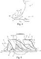
- Fig. 4
- eine Schnittdarstellung durch ein Verdichterrad gemäß einer Variante der alternativen Ausführungsform,
- Fig. 5
- eine Seitenansicht auf ein Verdichterrad gemäß der
Fig. 4 . - Entsprechend den
Fig. 1 - 5 , weist ein Verdichterrad 1 für einen Abgasturbolader 2 einen Nabengrundkörper 3 sowie daran angeordnete Schaufelblätter 4 auf. InFig. 1 sind lediglich der Nabengrundkörper 3, nicht jedoch die zugehörigen Schaufelblätter 4 dargestellt. Um nun das Verdichterrad 1 hinsichtlich einer im Bereich eines Übergangs 7 zwischen dem jeweiligen Schaufelblatt 4 und dem Nabengrundkörper 3 auftretenden Spannung optimieren zu können, ist eine erfindungsgemäße Ausführungsform in denFig. 1 und 2 dargestellt. Eine nicht erfindungsgemäße Ausführungsform ist in denFig. 3 bis 5 dargestellt. - Gemäß den
Fig. 1 und 2 ist dabei der Nabengrundkörper 3 erfindungsgemäß als Vieleck mit einer der Anzahl der Schaufelblätter 4 entsprechenden Anzahl an zueinander gekippten Segmenten 5 ausgebildet. Die einzelnen Segmente 5 (vergleiche auch dieFigur 2 ) weisen dabei vorzugsweise zumindest radial außen eine im Querschnitt gerade Grundfläche 6 auf, die je nach Anforderungen unterschiedlich stark zum Nabengrundkörper 3 bzw. zum jeweiligen Schaufelblatt 4 und auch zueinander gekippt sein können. Der Übergang 7 von einem Segment 5 in ein zugehöriges Schaufelblatt 4 ist dabei vorzugsweise ausgerundet, wobei die Ausrundung bzw. der ausgerundete Übergang 7 durch eine Materialzugabe 8, das heißt einen zusätzlichen Materialauftrag, zur Grundfläche 6 des jeweiligen Segments 5 gebildet ist. - Im Vergleich zu aus dem Stand der Technik bekannten Nabengrundkörpern, bei welchen diese ausschließlich als runder Drehkörper ausgebildet waren, bietet der erfindungsgemäße Nabengrundkörper 3 und damit auch das erfindungsgemäße Verdichterrad 1 den großen Vorteil, dass dieses ausschließlich lokal in demjenigen Bereich verstärkt ist, in welchem die beim Betrieb des Abgasturboladers 2 auftretenden Spannungen am höchsten sind. Durch die Ausrundung kann darüber hinaus ein kerbfreier Übergang sowohl in die Grundfläche 6 des Segmentes 5 als auch in das zugehörige Schaufelblatt 4 erreicht werden, wodurch Spannungsspitzen vermieden werden können.
- Betrachtet man das Verdichterrad 1 gemäß der Ausführungsform in
Fig. 3 , so kann man erkennen, dass der Nabengrundkörper 3 hier eine den Schaufelblättern zugewandte und in Umfangsrichtung wellige Grundfläche 6 aufweist, wobei eine Anzahl der einzelnen Wellen 10 einer Anzahl der Schaufelblätter 4 entspricht. Zusätzlich ist in diesem Fall auch ein Rücken der Grundfläche 6 bzw. des Nabengrundkörpers 3 wellig ausgebildet, wobei die Wellen 10 des Rückens 9 und der Grundfläche 6 parallel verlaufen. Selbstverständlich kann dabei der Rücken 9 auch ohne derartige Wellen, das heißt gerade ausgebildet sein, wobei in diesem Zusammenhang auch der Rücken 9 am Nabengrundkörper 3 des Verdichterrades 1 gemäß denFig. 1 und 2 gerade oder aber mit Wellen 10 ausgebildet sein kann. Ein Übergang 7 von der Grundfläche 6 in ein zugehöriges Schaufelblatt 4 ist dabei bevorzugt im Bereich eines Wellenberges 11 bzw. zumindest geringfügig daneben angeordnet Darüber hinaus kann vorgesehen sein, dass ein Übergang 7 zwischen der welligen Grundfläche 6 und dem zugehörigen Schaufelblatt 4 ausgerundet ist, wie dies gemäß derFig. 3 mit unterbrochen gezeichneter Linie dargestellt ist, wobei ein derartig ausgerundeter Übergang 7 durch eine an einen Wellenhang 12 angelegte Tangente in die Grundfläche 6 übergeht. In ähnlicher Weise kann auch ein tangentialer Übergang in das zugehörige Schaufelblatt 4 erreicht werden. - Bei beiden gezeigten, alternativen aber dennoch in Bezug auf die Spannungs- und Gewichtsoptimierung gleichwertigen Ausführungsformen ist dabei gemein, dass diese durch eine spezielle, bislang nicht da gewesene Ausgestaltung bzw. Formänderung des Nabengrundkörpers 3 besonders die im Bereich eines Übergangs 7 von einer Grundfläche 6 des Nabengrundkörpers 3 in das zugehörige Schaufelblatt 4 auftretenden, hohen Spannungen besser aufzunehmen vermögen und dadurch eine längere Lebensdauer gewährleisten. Im Vergleich zu gänzlich, das heißt an allen Stellen, aufgedickten Nabengrundkörpern ist ein derartiger, erfindungsgemäßer und lediglich lokal verstärkter Nabengrundkörper 3 selbstverständlich deutlich leichter und besitzt dadurch ein reduziertes Massenträgheitsmoment, wodurch ein mit diesem Verdichterrad 1 ausgestatteter Abgasturbolader 2 ein verbessertes Ansprechverhalten zeigt.
- Üblicherweise ist dabei allen Ausführungsformen gemäß den
Figuren 3 bis 5 gemein, dass die Wellenberge 11 jeweils zwischen zwei Schaufelblättern 4 angeordnet sind. - Betrachtet man das Verdichterrad 1 gemäß der
Figur 4 , so kann man erkennen, dass die Wellenberge 11 nach radial innen und/oder nach radial außen auslaufen und in die Grundfläche 6 übergehen, sodass an einem Verdichterradeintritt 13 und einem Verdichterradaustritt 14 keine Wellenberge 11 vorhanden sind. In Figur 4 ist dabei der ursprüngliche Verlauf eines Verdichterrades nach dem Stand der Technik mit durchgezogener Linie gezeichnet, während der Verlauf des als Alternative beschriebenen Verdichterrades 1 im Bereich des Wellenberges 11 mit punktierter Linie gezeichnet ist. Der Nabengrundkörper 3 weist bei einem Verdichterrad 1 gemäß denFiguren 4 und 5 einen ebenen Rücken 9 auf. - Die radiale Position der Wellenberge 11 können dabei im Verhältnis zur Verdichterradgröße (Verdichterradradius) aus dem Quotienten "Radius-VR / Position Wellenberg" gebildet werden. Dabei hat sich herausgestellt, dass sich der Wellenberg 11 im Verhältnis zum Radius RVR des Verdichterrades 1 zwischen 1,1 und 2,2 aufhält. Für ein Verhältnis eines Radius RVR des Verdichterrades 1 zu einer maximalen Radialerstreckung RWB des Wellenberges 11 gilt deshalb

- Die Aufdickung, insbesondere Materialzugaben 8, der Wellenberge 11 ist somit nur im Zwischenbereich zwischen zwei benachbarten Schaufelblättern 4 vorhanden. Je nachdem, wo der hochbelastete Bereich ist, sieht der Verlauf anders aus. Bei allen Verläufen ist jedoch gleich, dass sie nicht rotationssymmetrisch sind und sowohl in Richtung Verdichterradeinritt 13 als auch in Richtung Verdichterradaustritt 14 wieder auf den ursprünglichen, rotationssymmetrischen Nabenverlauf zurückgehen. Hierdurch können thermodynamische Nachteile vermieden werden.
Claims (5)
- Verdichterrad (1) für einen Abgasturbolader (2) mit einem Nabengrundkörper (3) und daran angeordneten Schaufelblättern (4), wobei der Nabengrundkörper (3) als Vieleck mit einer der Anzahl der Schaufelblätter (4) entsprechenden Anzahl an zueinander gekippten Segmenten (5) ausgebildet ist,
dadurch gekennzeichnet,
dass die einzelnen Segmente (5) radial außen eine im Querschnitt gerade Grundfläche (6) aufweisen und radial außen sägezahnartig ineinander übergehen. - Verdichterrad nach Anspruch 1,
dadurch gekennzeichnet, dass
ein Übergang (7) von einem Segment (5) in ein zugehöriges Schaufelblatt (4) ausgerundet ist. - Verdichterrad nach Anspruch 2,
dadurch gekennzeichnet, dass
der ausgerundete Übergang (7) durch eine Materialzugabe (8) zur Grundfläche (6) des jeweiligen Segments (5) gebildet ist. - Verdichterrad nach einem der vorherigen Ansprüche,
dadurch gekennzeichnet, dass
dass der Nabengrundkörper (3) einen in Umfangsrichtung welligen Rücken (9) aufweist. - Abgasturbolader (2) mit einem Verdichterrad (1) nach einem der vorhergehenden Ansprüche.
Applications Claiming Priority (1)
| Application Number | Priority Date | Filing Date | Title |
|---|---|---|---|
| DE102015214854.8A DE102015214854A1 (de) | 2015-08-04 | 2015-08-04 | Verdichterrad für einen Abgasturbolader |
Publications (2)
| Publication Number | Publication Date |
|---|---|
| EP3128181A1 EP3128181A1 (de) | 2017-02-08 |
| EP3128181B1 true EP3128181B1 (de) | 2019-09-04 |
Family
ID=56550136
Family Applications (1)
| Application Number | Title | Priority Date | Filing Date |
|---|---|---|---|
| EP16181125.2A Active EP3128181B1 (de) | 2015-08-04 | 2016-07-26 | Verdichterrad für einen abgasturbolader |
Country Status (4)
| Country | Link |
|---|---|
| US (1) | US10689982B2 (de) |
| EP (1) | EP3128181B1 (de) |
| CN (1) | CN106438461B (de) |
| DE (1) | DE102015214854A1 (de) |
Families Citing this family (6)
| Publication number | Priority date | Publication date | Assignee | Title |
|---|---|---|---|---|
| JP2020514610A (ja) * | 2016-12-23 | 2020-05-21 | ボーグワーナー インコーポレーテッド | ターボチャージャー及びタービンホイール |
| US20190112927A1 (en) * | 2017-10-12 | 2019-04-18 | Borgwarner Inc. | Turbocharger having improved turbine wheel |
| DE102019211515A1 (de) | 2019-08-01 | 2021-02-04 | Vitesco Technologies GmbH | Turbinenlaufrad einer Abgasturbine und Abgasturbolader für eine Brennkraftmaschine |
| DE102021133772B3 (de) | 2021-12-18 | 2023-01-19 | Borgwarner Inc. | Verdichterrad |
| DE102021133773B3 (de) | 2021-12-18 | 2023-02-09 | Borgwarner Inc. | Verdichterrad |
| DE102023126038A1 (de) * | 2023-09-26 | 2025-03-27 | Ebm-Papst St. Georgen Gmbh & Co. Kg | Lüfterrad mit einer eine Welligkeit aufweisenden Begrenzungsfläche sowie Lüfter mit einem solchen Lüfterrad |
Family Cites Families (13)
| Publication number | Priority date | Publication date | Assignee | Title |
|---|---|---|---|---|
| FR1002707A (fr) * | 1948-12-14 | 1952-03-10 | Belliss & Morcom Ltd | Perfectionnements aux pompes centrifuges, compresseurs d'air ou autres gaz et appareils analogues |
| US2918254A (en) * | 1954-05-10 | 1959-12-22 | Hausammann Werner | Turborunner |
| US5215439A (en) * | 1991-01-15 | 1993-06-01 | Northern Research & Engineering Corp. | Arbitrary hub for centrifugal impellers |
| WO1992013197A1 (en) * | 1991-01-15 | 1992-08-06 | Northern Research & Engineering Corporation | Arbitrary hub for centrifugal impellers |
| US6471474B1 (en) * | 2000-10-20 | 2002-10-29 | General Electric Company | Method and apparatus for reducing rotor assembly circumferential rim stress |
| JP2008163760A (ja) * | 2006-12-27 | 2008-07-17 | Ihi Corp | ラジアルインペラ、過給機 |
| FR2931214B1 (fr) | 2008-05-15 | 2013-07-26 | Turbomeca | Pale de rouet de compresseur a raccordement evolutif |
| CN101666326B (zh) * | 2008-09-04 | 2011-08-17 | 杨圣安 | 组合式叶轮 |
| JP2011021491A (ja) * | 2009-07-13 | 2011-02-03 | Mitsubishi Heavy Ind Ltd | インペラおよび回転機械 |
| JP2011021492A (ja) * | 2009-07-13 | 2011-02-03 | Mitsubishi Heavy Ind Ltd | インペラおよび回転機械 |
| WO2011042515A1 (en) * | 2009-10-08 | 2011-04-14 | Cardo Production Wexford Limited | A pump impeller |
| US9988907B2 (en) * | 2011-04-25 | 2018-06-05 | Honeywell International, Inc. | Blade features for turbocharger wheel |
| DE102012106810B4 (de) * | 2012-07-26 | 2020-08-27 | Ihi Charging Systems International Gmbh | Laufrad für eine Fluidenergiemaschine |
-
2015
- 2015-08-04 DE DE102015214854.8A patent/DE102015214854A1/de not_active Withdrawn
-
2016
- 2016-07-26 EP EP16181125.2A patent/EP3128181B1/de active Active
- 2016-08-01 CN CN201610622313.XA patent/CN106438461B/zh active Active
- 2016-08-03 US US15/227,933 patent/US10689982B2/en active Active
Non-Patent Citations (1)
| Title |
|---|
| None * |
Also Published As
| Publication number | Publication date |
|---|---|
| US10689982B2 (en) | 2020-06-23 |
| EP3128181A1 (de) | 2017-02-08 |
| CN106438461B (zh) | 2021-02-09 |
| US20170037729A1 (en) | 2017-02-09 |
| CN106438461A (zh) | 2017-02-22 |
| DE102015214854A1 (de) | 2017-02-09 |
Similar Documents
| Publication | Publication Date | Title |
|---|---|---|
| EP3128181A1 (de) | Verdichterrad für einen abgasturbolader | |
| EP2376746B1 (de) | Deckbandsegment einer schaufel | |
| EP2949910B1 (de) | Schubumkehrkaskadenelement einer fluggasturbine | |
| EP2505783B1 (de) | Rotor einer Axialverdichterstufe einer Turbomaschine | |
| EP2356320B1 (de) | Ringdiffusor für eine axialturbomaschine | |
| EP2746534B1 (de) | Stator- und/oder Rotorstufe einer Strömungsmaschine, sowie zugehörige Gasturbine | |
| WO2014015959A1 (de) | Laufrad für eine fluidenergiemaschine | |
| DE102015224283A1 (de) | Leitschaufelcluster für eine Strömungsmaschine | |
| EP2762684B1 (de) | Dichtungsträger aus titanaluminid für eine strömungsmaschine | |
| EP3571416B1 (de) | Gedecktes radialgebläserad mit einer periodisch und asymmetrisch geformten scheibe | |
| EP2966308A2 (de) | Axiallager | |
| EP1114241A1 (de) | Dichtring für nicht-hermetische fluiddichtungen | |
| EP1690011B1 (de) | Rotor für einen verdichter | |
| EP2410132B1 (de) | Verdichterschaufel eines Gasturbinentriebwerks mit selbstschärfender Vorderkantenstruktur | |
| EP3056677B1 (de) | Schaufel und Strömungsmaschine | |
| EP2994615B1 (de) | Rotor für eine thermische strömungsmaschine | |
| EP2696039B1 (de) | Gasturbinenstufe | |
| EP1515001B1 (de) | Laufschaufelbindung einer Turbomaschine | |
| EP3183430B1 (de) | Turbinenlaufschaufel | |
| EP3309359A1 (de) | Laufschaufelbaugruppe für ein triebwerk | |
| WO2009112242A2 (de) | Deckscheibe für ein geschlossenes laufrad | |
| EP3401503A1 (de) | Rotorvorrichtung einer strömungsmaschine | |
| EP3885535B1 (de) | Dichtring für einen rotor und rotor mit einem solchen | |
| DE102010020307A1 (de) | Laufrad für eine Fluidenergiemaschine | |
| DE102016220133A1 (de) | Laufrad für einen Abgasturbolader und Abgasturbolader mit einem solchen Laufrad |
Legal Events
| Date | Code | Title | Description |
|---|---|---|---|
| PUAI | Public reference made under article 153(3) epc to a published international application that has entered the european phase |
Free format text: ORIGINAL CODE: 0009012 |
|
| STAA | Information on the status of an ep patent application or granted ep patent |
Free format text: STATUS: THE APPLICATION HAS BEEN PUBLISHED |
|
| AK | Designated contracting states |
Kind code of ref document: A1 Designated state(s): AL AT BE BG CH CY CZ DE DK EE ES FI FR GB GR HR HU IE IS IT LI LT LU LV MC MK MT NL NO PL PT RO RS SE SI SK SM TR |
|
| AX | Request for extension of the european patent |
Extension state: BA ME |
|
| STAA | Information on the status of an ep patent application or granted ep patent |
Free format text: STATUS: REQUEST FOR EXAMINATION WAS MADE |
|
| 17P | Request for examination filed |
Effective date: 20170412 |
|
| RBV | Designated contracting states (corrected) |
Designated state(s): AL AT BE BG CH CY CZ DE DK EE ES FI FR GB GR HR HU IE IS IT LI LT LU LV MC MK MT NL NO PL PT RO RS SE SI SK SM TR |
|
| RAP1 | Party data changed (applicant data changed or rights of an application transferred) |
Owner name: BMTS TECHNOLOGY GMBH & CO. KG |
|
| STAA | Information on the status of an ep patent application or granted ep patent |
Free format text: STATUS: EXAMINATION IS IN PROGRESS |
|
| 17Q | First examination report despatched |
Effective date: 20190408 |
|
| GRAP | Despatch of communication of intention to grant a patent |
Free format text: ORIGINAL CODE: EPIDOSNIGR1 |
|
| STAA | Information on the status of an ep patent application or granted ep patent |
Free format text: STATUS: GRANT OF PATENT IS INTENDED |
|
| INTG | Intention to grant announced |
Effective date: 20190603 |
|
| GRAS | Grant fee paid |
Free format text: ORIGINAL CODE: EPIDOSNIGR3 |
|
| GRAA | (expected) grant |
Free format text: ORIGINAL CODE: 0009210 |
|
| STAA | Information on the status of an ep patent application or granted ep patent |
Free format text: STATUS: THE PATENT HAS BEEN GRANTED |
|
| AK | Designated contracting states |
Kind code of ref document: B1 Designated state(s): AL AT BE BG CH CY CZ DE DK EE ES FI FR GB GR HR HU IE IS IT LI LT LU LV MC MK MT NL NO PL PT RO RS SE SI SK SM TR |
|
| REG | Reference to a national code |
Ref country code: GB Ref legal event code: FG4D Free format text: NOT ENGLISH |
|
| REG | Reference to a national code |
Ref country code: CH Ref legal event code: EP |
|
| REG | Reference to a national code |
Ref country code: AT Ref legal event code: REF Ref document number: 1175731 Country of ref document: AT Kind code of ref document: T Effective date: 20190915 |
|
| REG | Reference to a national code |
Ref country code: DE Ref legal event code: R096 Ref document number: 502016006389 Country of ref document: DE |
|
| REG | Reference to a national code |
Ref country code: IE Ref legal event code: FG4D Free format text: LANGUAGE OF EP DOCUMENT: GERMAN |
|
| REG | Reference to a national code |
Ref country code: NL Ref legal event code: MP Effective date: 20190904 |
|
| REG | Reference to a national code |
Ref country code: LT Ref legal event code: MG4D |
|
| PG25 | Lapsed in a contracting state [announced via postgrant information from national office to epo] |
Ref country code: NO Free format text: LAPSE BECAUSE OF FAILURE TO SUBMIT A TRANSLATION OF THE DESCRIPTION OR TO PAY THE FEE WITHIN THE PRESCRIBED TIME-LIMIT Effective date: 20191204 Ref country code: BG Free format text: LAPSE BECAUSE OF FAILURE TO SUBMIT A TRANSLATION OF THE DESCRIPTION OR TO PAY THE FEE WITHIN THE PRESCRIBED TIME-LIMIT Effective date: 20191204 Ref country code: SE Free format text: LAPSE BECAUSE OF FAILURE TO SUBMIT A TRANSLATION OF THE DESCRIPTION OR TO PAY THE FEE WITHIN THE PRESCRIBED TIME-LIMIT Effective date: 20190904 Ref country code: FI Free format text: LAPSE BECAUSE OF FAILURE TO SUBMIT A TRANSLATION OF THE DESCRIPTION OR TO PAY THE FEE WITHIN THE PRESCRIBED TIME-LIMIT Effective date: 20190904 Ref country code: LT Free format text: LAPSE BECAUSE OF FAILURE TO SUBMIT A TRANSLATION OF THE DESCRIPTION OR TO PAY THE FEE WITHIN THE PRESCRIBED TIME-LIMIT Effective date: 20190904 Ref country code: HR Free format text: LAPSE BECAUSE OF FAILURE TO SUBMIT A TRANSLATION OF THE DESCRIPTION OR TO PAY THE FEE WITHIN THE PRESCRIBED TIME-LIMIT Effective date: 20190904 |
|
| PG25 | Lapsed in a contracting state [announced via postgrant information from national office to epo] |
Ref country code: GR Free format text: LAPSE BECAUSE OF FAILURE TO SUBMIT A TRANSLATION OF THE DESCRIPTION OR TO PAY THE FEE WITHIN THE PRESCRIBED TIME-LIMIT Effective date: 20191205 Ref country code: ES Free format text: LAPSE BECAUSE OF FAILURE TO SUBMIT A TRANSLATION OF THE DESCRIPTION OR TO PAY THE FEE WITHIN THE PRESCRIBED TIME-LIMIT Effective date: 20190904 Ref country code: RS Free format text: LAPSE BECAUSE OF FAILURE TO SUBMIT A TRANSLATION OF THE DESCRIPTION OR TO PAY THE FEE WITHIN THE PRESCRIBED TIME-LIMIT Effective date: 20190904 Ref country code: LV Free format text: LAPSE BECAUSE OF FAILURE TO SUBMIT A TRANSLATION OF THE DESCRIPTION OR TO PAY THE FEE WITHIN THE PRESCRIBED TIME-LIMIT Effective date: 20190904 Ref country code: AL Free format text: LAPSE BECAUSE OF FAILURE TO SUBMIT A TRANSLATION OF THE DESCRIPTION OR TO PAY THE FEE WITHIN THE PRESCRIBED TIME-LIMIT Effective date: 20190904 |
|
| PG25 | Lapsed in a contracting state [announced via postgrant information from national office to epo] |
Ref country code: PT Free format text: LAPSE BECAUSE OF FAILURE TO SUBMIT A TRANSLATION OF THE DESCRIPTION OR TO PAY THE FEE WITHIN THE PRESCRIBED TIME-LIMIT Effective date: 20200106 Ref country code: PL Free format text: LAPSE BECAUSE OF FAILURE TO SUBMIT A TRANSLATION OF THE DESCRIPTION OR TO PAY THE FEE WITHIN THE PRESCRIBED TIME-LIMIT Effective date: 20190904 Ref country code: NL Free format text: LAPSE BECAUSE OF FAILURE TO SUBMIT A TRANSLATION OF THE DESCRIPTION OR TO PAY THE FEE WITHIN THE PRESCRIBED TIME-LIMIT Effective date: 20190904 Ref country code: RO Free format text: LAPSE BECAUSE OF FAILURE TO SUBMIT A TRANSLATION OF THE DESCRIPTION OR TO PAY THE FEE WITHIN THE PRESCRIBED TIME-LIMIT Effective date: 20190904 Ref country code: IT Free format text: LAPSE BECAUSE OF FAILURE TO SUBMIT A TRANSLATION OF THE DESCRIPTION OR TO PAY THE FEE WITHIN THE PRESCRIBED TIME-LIMIT Effective date: 20190904 Ref country code: EE Free format text: LAPSE BECAUSE OF FAILURE TO SUBMIT A TRANSLATION OF THE DESCRIPTION OR TO PAY THE FEE WITHIN THE PRESCRIBED TIME-LIMIT Effective date: 20190904 |
|
| PG25 | Lapsed in a contracting state [announced via postgrant information from national office to epo] |
Ref country code: IS Free format text: LAPSE BECAUSE OF FAILURE TO SUBMIT A TRANSLATION OF THE DESCRIPTION OR TO PAY THE FEE WITHIN THE PRESCRIBED TIME-LIMIT Effective date: 20200224 Ref country code: CZ Free format text: LAPSE BECAUSE OF FAILURE TO SUBMIT A TRANSLATION OF THE DESCRIPTION OR TO PAY THE FEE WITHIN THE PRESCRIBED TIME-LIMIT Effective date: 20190904 Ref country code: SK Free format text: LAPSE BECAUSE OF FAILURE TO SUBMIT A TRANSLATION OF THE DESCRIPTION OR TO PAY THE FEE WITHIN THE PRESCRIBED TIME-LIMIT Effective date: 20190904 Ref country code: SM Free format text: LAPSE BECAUSE OF FAILURE TO SUBMIT A TRANSLATION OF THE DESCRIPTION OR TO PAY THE FEE WITHIN THE PRESCRIBED TIME-LIMIT Effective date: 20190904 |
|
| REG | Reference to a national code |
Ref country code: DE Ref legal event code: R097 Ref document number: 502016006389 Country of ref document: DE |
|
| PLBE | No opposition filed within time limit |
Free format text: ORIGINAL CODE: 0009261 |
|
| STAA | Information on the status of an ep patent application or granted ep patent |
Free format text: STATUS: NO OPPOSITION FILED WITHIN TIME LIMIT |
|
| PG2D | Information on lapse in contracting state deleted |
Ref country code: IS |
|
| PG25 | Lapsed in a contracting state [announced via postgrant information from national office to epo] |
Ref country code: DK Free format text: LAPSE BECAUSE OF FAILURE TO SUBMIT A TRANSLATION OF THE DESCRIPTION OR TO PAY THE FEE WITHIN THE PRESCRIBED TIME-LIMIT Effective date: 20190904 Ref country code: IS Free format text: LAPSE BECAUSE OF FAILURE TO SUBMIT A TRANSLATION OF THE DESCRIPTION OR TO PAY THE FEE WITHIN THE PRESCRIBED TIME-LIMIT Effective date: 20200105 |
|
| 26N | No opposition filed |
Effective date: 20200605 |
|
| PG25 | Lapsed in a contracting state [announced via postgrant information from national office to epo] |
Ref country code: SI Free format text: LAPSE BECAUSE OF FAILURE TO SUBMIT A TRANSLATION OF THE DESCRIPTION OR TO PAY THE FEE WITHIN THE PRESCRIBED TIME-LIMIT Effective date: 20190904 |
|
| PG25 | Lapsed in a contracting state [announced via postgrant information from national office to epo] |
Ref country code: MC Free format text: LAPSE BECAUSE OF FAILURE TO SUBMIT A TRANSLATION OF THE DESCRIPTION OR TO PAY THE FEE WITHIN THE PRESCRIBED TIME-LIMIT Effective date: 20190904 |
|
| REG | Reference to a national code |
Ref country code: CH Ref legal event code: PL |
|
| REG | Reference to a national code |
Ref country code: BE Ref legal event code: MM Effective date: 20200731 |
|
| PG25 | Lapsed in a contracting state [announced via postgrant information from national office to epo] |
Ref country code: LI Free format text: LAPSE BECAUSE OF NON-PAYMENT OF DUE FEES Effective date: 20200731 Ref country code: LU Free format text: LAPSE BECAUSE OF NON-PAYMENT OF DUE FEES Effective date: 20200726 Ref country code: CH Free format text: LAPSE BECAUSE OF NON-PAYMENT OF DUE FEES Effective date: 20200731 |
|
| PG25 | Lapsed in a contracting state [announced via postgrant information from national office to epo] |
Ref country code: BE Free format text: LAPSE BECAUSE OF NON-PAYMENT OF DUE FEES Effective date: 20200731 |
|
| PG25 | Lapsed in a contracting state [announced via postgrant information from national office to epo] |
Ref country code: IE Free format text: LAPSE BECAUSE OF NON-PAYMENT OF DUE FEES Effective date: 20200726 |
|
| REG | Reference to a national code |
Ref country code: DE Ref legal event code: R082 Ref document number: 502016006389 Country of ref document: DE |
|
| PG25 | Lapsed in a contracting state [announced via postgrant information from national office to epo] |
Ref country code: TR Free format text: LAPSE BECAUSE OF FAILURE TO SUBMIT A TRANSLATION OF THE DESCRIPTION OR TO PAY THE FEE WITHIN THE PRESCRIBED TIME-LIMIT Effective date: 20190904 Ref country code: MT Free format text: LAPSE BECAUSE OF FAILURE TO SUBMIT A TRANSLATION OF THE DESCRIPTION OR TO PAY THE FEE WITHIN THE PRESCRIBED TIME-LIMIT Effective date: 20190904 Ref country code: CY Free format text: LAPSE BECAUSE OF FAILURE TO SUBMIT A TRANSLATION OF THE DESCRIPTION OR TO PAY THE FEE WITHIN THE PRESCRIBED TIME-LIMIT Effective date: 20190904 |
|
| PG25 | Lapsed in a contracting state [announced via postgrant information from national office to epo] |
Ref country code: MK Free format text: LAPSE BECAUSE OF FAILURE TO SUBMIT A TRANSLATION OF THE DESCRIPTION OR TO PAY THE FEE WITHIN THE PRESCRIBED TIME-LIMIT Effective date: 20190904 |
|
| REG | Reference to a national code |
Ref country code: AT Ref legal event code: MM01 Ref document number: 1175731 Country of ref document: AT Kind code of ref document: T Effective date: 20210726 |
|
| PG25 | Lapsed in a contracting state [announced via postgrant information from national office to epo] |
Ref country code: AT Free format text: LAPSE BECAUSE OF NON-PAYMENT OF DUE FEES Effective date: 20210726 |
|
| PGFP | Annual fee paid to national office [announced via postgrant information from national office to epo] |
Ref country code: DE Payment date: 20250722 Year of fee payment: 10 |
|
| PGFP | Annual fee paid to national office [announced via postgrant information from national office to epo] |
Ref country code: GB Payment date: 20250722 Year of fee payment: 10 |
|
| PGFP | Annual fee paid to national office [announced via postgrant information from national office to epo] |
Ref country code: FR Payment date: 20250725 Year of fee payment: 10 |