EP3128207A1 - Transmission à variation continue de type à disques biseautés - Google Patents
Transmission à variation continue de type à disques biseautés Download PDFInfo
- Publication number
- EP3128207A1 EP3128207A1 EP14886159.4A EP14886159A EP3128207A1 EP 3128207 A1 EP3128207 A1 EP 3128207A1 EP 14886159 A EP14886159 A EP 14886159A EP 3128207 A1 EP3128207 A1 EP 3128207A1
- Authority
- EP
- European Patent Office
- Prior art keywords
- pressing
- cone
- driven
- driving
- cam
- Prior art date
- Legal status (The legal status is an assumption and is not a legal conclusion. Google has not performed a legal analysis and makes no representation as to the accuracy of the status listed.)
- Granted
Links
- 230000005540 biological transmission Effects 0.000 title claims abstract description 88
- 238000003825 pressing Methods 0.000 claims abstract description 173
- 230000007246 mechanism Effects 0.000 claims abstract description 86
- 238000006243 chemical reaction Methods 0.000 claims abstract description 8
- 238000005096 rolling process Methods 0.000 claims description 26
- 238000003754 machining Methods 0.000 description 5
- 230000008901 benefit Effects 0.000 description 3
- 230000008859 change Effects 0.000 description 3
- 238000006073 displacement reaction Methods 0.000 description 3
- 238000005265 energy consumption Methods 0.000 description 3
- 230000001052 transient effect Effects 0.000 description 3
- 238000000034 method Methods 0.000 description 2
- 230000035945 sensitivity Effects 0.000 description 2
- 230000009286 beneficial effect Effects 0.000 description 1
- 239000003638 chemical reducing agent Substances 0.000 description 1
- 238000010276 construction Methods 0.000 description 1
- 230000007547 defect Effects 0.000 description 1
- 230000007812 deficiency Effects 0.000 description 1
- 230000000694 effects Effects 0.000 description 1
- 239000002184 metal Substances 0.000 description 1
- 230000009467 reduction Effects 0.000 description 1
- 239000000523 sample Substances 0.000 description 1
- 230000001360 synchronised effect Effects 0.000 description 1
Images



Classifications
-
- F—MECHANICAL ENGINEERING; LIGHTING; HEATING; WEAPONS; BLASTING
- F16—ENGINEERING ELEMENTS AND UNITS; GENERAL MEASURES FOR PRODUCING AND MAINTAINING EFFECTIVE FUNCTIONING OF MACHINES OR INSTALLATIONS; THERMAL INSULATION IN GENERAL
- F16H—GEARING
- F16H61/00—Control functions within control units of change-speed- or reversing-gearings for conveying rotary motion ; Control of exclusively fluid gearing, friction gearing, gearings with endless flexible members or other particular types of gearing
- F16H61/66—Control functions within control units of change-speed- or reversing-gearings for conveying rotary motion ; Control of exclusively fluid gearing, friction gearing, gearings with endless flexible members or other particular types of gearing specially adapted for continuously variable gearings
- F16H61/662—Control functions within control units of change-speed- or reversing-gearings for conveying rotary motion ; Control of exclusively fluid gearing, friction gearing, gearings with endless flexible members or other particular types of gearing specially adapted for continuously variable gearings with endless flexible members
- F16H61/66272—Control functions within control units of change-speed- or reversing-gearings for conveying rotary motion ; Control of exclusively fluid gearing, friction gearing, gearings with endless flexible members or other particular types of gearing specially adapted for continuously variable gearings with endless flexible members characterised by means for controlling the torque transmitting capability of the gearing
-
- F—MECHANICAL ENGINEERING; LIGHTING; HEATING; WEAPONS; BLASTING
- F16—ENGINEERING ELEMENTS AND UNITS; GENERAL MEASURES FOR PRODUCING AND MAINTAINING EFFECTIVE FUNCTIONING OF MACHINES OR INSTALLATIONS; THERMAL INSULATION IN GENERAL
- F16H—GEARING
- F16H9/00—Gearings for conveying rotary motion with variable gear ratio, or for reversing rotary motion, by endless flexible members
- F16H9/02—Gearings for conveying rotary motion with variable gear ratio, or for reversing rotary motion, by endless flexible members without members having orbital motion
- F16H9/04—Gearings for conveying rotary motion with variable gear ratio, or for reversing rotary motion, by endless flexible members without members having orbital motion using belts, V-belts, or ropes
- F16H9/12—Gearings for conveying rotary motion with variable gear ratio, or for reversing rotary motion, by endless flexible members without members having orbital motion using belts, V-belts, or ropes engaging a pulley built-up out of relatively axially-adjustable parts in which the belt engages the opposite flanges of the pulley directly without interposed belt-supporting members
- F16H9/16—Gearings for conveying rotary motion with variable gear ratio, or for reversing rotary motion, by endless flexible members without members having orbital motion using belts, V-belts, or ropes engaging a pulley built-up out of relatively axially-adjustable parts in which the belt engages the opposite flanges of the pulley directly without interposed belt-supporting members using two pulleys, both built-up out of adjustable conical parts
- F16H9/18—Gearings for conveying rotary motion with variable gear ratio, or for reversing rotary motion, by endless flexible members without members having orbital motion using belts, V-belts, or ropes engaging a pulley built-up out of relatively axially-adjustable parts in which the belt engages the opposite flanges of the pulley directly without interposed belt-supporting members using two pulleys, both built-up out of adjustable conical parts only one flange of each pulley being adjustable
-
- F—MECHANICAL ENGINEERING; LIGHTING; HEATING; WEAPONS; BLASTING
- F16—ENGINEERING ELEMENTS AND UNITS; GENERAL MEASURES FOR PRODUCING AND MAINTAINING EFFECTIVE FUNCTIONING OF MACHINES OR INSTALLATIONS; THERMAL INSULATION IN GENERAL
- F16H—GEARING
- F16H25/00—Gearings comprising primarily only cams, cam-followers and screw-and-nut mechanisms
- F16H25/18—Gearings comprising primarily only cams, cam-followers and screw-and-nut mechanisms for conveying or interconverting oscillating or reciprocating motions
- F16H25/20—Screw mechanisms
- F16H25/22—Screw mechanisms with balls, rollers, or similar members between the co-operating parts; Elements essential to the use of such members
- F16H25/2204—Screw mechanisms with balls, rollers, or similar members between the co-operating parts; Elements essential to the use of such members with balls
-
- F—MECHANICAL ENGINEERING; LIGHTING; HEATING; WEAPONS; BLASTING
- F16—ENGINEERING ELEMENTS AND UNITS; GENERAL MEASURES FOR PRODUCING AND MAINTAINING EFFECTIVE FUNCTIONING OF MACHINES OR INSTALLATIONS; THERMAL INSULATION IN GENERAL
- F16H—GEARING
- F16H55/00—Elements with teeth or friction surfaces for conveying motion; Worms, pulleys or sheaves for gearing mechanisms
- F16H55/32—Friction members
- F16H55/52—Pulleys or friction discs of adjustable construction
- F16H55/56—Pulleys or friction discs of adjustable construction of which the bearing parts are relatively axially adjustable
-
- F—MECHANICAL ENGINEERING; LIGHTING; HEATING; WEAPONS; BLASTING
- F16—ENGINEERING ELEMENTS AND UNITS; GENERAL MEASURES FOR PRODUCING AND MAINTAINING EFFECTIVE FUNCTIONING OF MACHINES OR INSTALLATIONS; THERMAL INSULATION IN GENERAL
- F16H—GEARING
- F16H61/00—Control functions within control units of change-speed- or reversing-gearings for conveying rotary motion ; Control of exclusively fluid gearing, friction gearing, gearings with endless flexible members or other particular types of gearing
- F16H61/66—Control functions within control units of change-speed- or reversing-gearings for conveying rotary motion ; Control of exclusively fluid gearing, friction gearing, gearings with endless flexible members or other particular types of gearing specially adapted for continuously variable gearings
- F16H61/662—Control functions within control units of change-speed- or reversing-gearings for conveying rotary motion ; Control of exclusively fluid gearing, friction gearing, gearings with endless flexible members or other particular types of gearing specially adapted for continuously variable gearings with endless flexible members
- F16H61/66254—Control functions within control units of change-speed- or reversing-gearings for conveying rotary motion ; Control of exclusively fluid gearing, friction gearing, gearings with endless flexible members or other particular types of gearing specially adapted for continuously variable gearings with endless flexible members controlling of shifting being influenced by a signal derived from the engine and the main coupling
-
- F—MECHANICAL ENGINEERING; LIGHTING; HEATING; WEAPONS; BLASTING
- F16—ENGINEERING ELEMENTS AND UNITS; GENERAL MEASURES FOR PRODUCING AND MAINTAINING EFFECTIVE FUNCTIONING OF MACHINES OR INSTALLATIONS; THERMAL INSULATION IN GENERAL
- F16H—GEARING
- F16H63/00—Control outputs from the control unit to change-speed- or reversing-gearings for conveying rotary motion or to other devices than the final output mechanism
- F16H63/02—Final output mechanisms therefor; Actuating means for the final output mechanisms
- F16H63/04—Final output mechanisms therefor; Actuating means for the final output mechanisms a single final output mechanism being moved by a single final actuating mechanism
- F16H63/06—Final output mechanisms therefor; Actuating means for the final output mechanisms a single final output mechanism being moved by a single final actuating mechanism the final output mechanism having an indefinite number of positions
- F16H63/067—Final output mechanisms therefor; Actuating means for the final output mechanisms a single final output mechanism being moved by a single final actuating mechanism the final output mechanism having an indefinite number of positions mechanical actuating means
Definitions
- the present invention relates to a transmission, in particular to a continuously variable transmission with cone discs.
- a continuously variable transmission with cone discs (hereinafter referred to as CVT) transmits power and rotation frictionally through a flexible transmission assembly clamped between the cone discs, such as rubber belts, push belts, or chains (hereinafter referred to as belts).
- CVTs are widely used in vehicles, construction machinery and other power machinery.
- the pressing system generates appropriate frictional force between the cone discs and the belts, while the ratio control system realizes an appropriate transmission ratio.
- the first engineered and the most commonly used at current are CVTs of which pressing and ratio control are controlled by two sets of hydraulic systems arranged on two movable cone discs, and the hydraulic control systems realize pressing and ratio control functions.
- the hydraulic pressing system in the CVT reacts and actuates relatively slowly, and cannot follow the transient change of external loads in real time, which often causes damage of CVT.
- the system hydraulic pressing force is generally designed much higher than actually needed, which causes low efficiency, high constructional loads, short life cycle, and low reliability.
- the system cannot respond to transient change of external loads, and besides, energy consumption and the machining costs of the hydraulic system are high.
- German company Luk discloses a real-time pressing method (which is applied in Audi's Multitronic Transmissions in a large scale) for movable cone discs using cams and hydraulic systems in Patents DE000004036683 , DE102006018806 , and Patent CN200780010525.1 .
- one slope surface forming the end surface cam is rigidly connected with the transmission shaft of the movable cone disc, and another cam is connected with a hydraulic piston; rollers are arranged between the two slope surfaces which generate torque-related axial force through the rollers between the two slope surfaces, and the axial force is added to hydraulic pressing force in the hydraulic piston.
- pressing force can respond to the transient change of loads, so that the hydraulic system pressing force requirements of pump, and resulted energy consumption can be reduced, and requirements for performance of the hydraulic pump can be reduced.
- the sliding range of the cam with engineering considerations is smaller than the axial sliding (about 15-20mm) required for ratio control of the movable cone disc, the method can only work in combination with the hydraulic system in CVT, but cannot be separately used as a pressing mechanism.
- LuK discloses a spatial cam structure for directly pressing the movable cone disc in Patent DE000010139119 .
- Such structure also has the problem to provide the enough axial sliding space required for ratio control of the movable cone disc because the spatial cam is still arranged on one side of the movable cone disc.
- the only solution of the problem is to enlarge the axial dimension of the cam.
- the dimension is a key parameter of transmission;
- the spatial cam has a radial slope angle less than the friction self-locking angle, so that the cam can be self-locked and cannot slide while the movable cone disc slides away from the pressing cone disc; in addition, when the input torque is reversing, like the vehicle coasts down and the engine turns to be driven, the rollers are going to slide to the other side of the slope. If the cam was too large, the rollers need much more time to slide, so that the belt slides, and the surfaces of cone discs can be damaged; furthermore, the spatial cam structure does not have forward and reverse pressing functions without considering the forward and reverse pressing problems.
- German Company PIV discloses a structure for pressing a stationary cone disc by using an end surface cam through a hydraulic system in DE3028490 .
- the pressing system adopting such structure is still a hydraulic system, wherein a main pressing cylinder is positioned on the backs of driving and driven movable cone discs, and besides, a hydraulic cylinder is arranged on the back of a driving stationary cone disc, and the end surface cam is connected with the other end of the hydraulic cylinder and the transmission shaft.
- the main pressing cylinder provides pressing force during normal operation, only in case of sudden load changes, the cam on the back of the driving stationary cone disc compresses the hydraulic cylinder rapidly, to increase the hydraulic pressing force to prevent sliding. Therefore, such structure has the same shortages, the pressing and ratio control are on the same movable cone disc.
- the pressing system using disc spring and ratio control using screw and electric motor are disclosed in recent years.
- Such CVTs are simple in structures, but have the shortage that pressing force is determined by disc springs and irrelevant with load; besides, the disc spring pressing mechanism and a screw ratio control mechanism are mounted on one side of the movable cone disc, and the transmission structure is not compact enough.
- Patent CN201875074U discloses a CVT with cone discs by using the screw pressing system.
- the CVT with cone discs comprises a pair of driving cone discs mounted on a driving shaft and a pair of driven cone discs mounted on a driven shaft; the driving cone discs and the driven cone discs clamp a flexible transmission element.
- the pressing mechanism of the CVT with cone discs consists of pressing screws and pressing nuts, which are mounted on the backs of driving movable cone discs and are in screw fit.
- a ratio control mechanism consists of hollow screws and nuts, which are arranged on the backs of the driving movable cone discs.
- the hollow screws and nuts adopt ball screw structures or sliding screw structures, and one of the hollow screws and nuts is fixedly connected with the driving movable cone discs, with ratio control gears on outer walls.
- a ratio control motor controls the ratio through a speed reducer and ratio control gears on the hollow screws or nuts.
- the CVT with cone discs has the following advantages: pressing force applied to the cone discs by the pressing mechanism can be adjusted in real time along with the changes in torque born by the transmission: when the transmitting torque is reduced, the pressing force is also reduced, thereby improving the transmitting efficiency of the CVT, reducing the loads of each component, and facilitating prolonging the service life of the system; besides, the transmission is simple in structure, and low in energy consumption and machining costs.
- the CVT also has shortages and deficiencies: firstly, the ratio control mechanism and the pressing mechanism are mounted on the same movable cone disc, so that the pressing mechanism also needs to meet the requirement of axial sliding for ratio control of the movable cone disc, resulting in large axial dimension and no-compact structure of the transmission; secondly, the pressing mechanism can only achieve one-way pressing without transmitting torque in a reverse direction, so that the CVT can only be applied in the case of transmitting motion and torque in an unidirectional manner.
- the present invention aims to provide a compact CVT with cone discs, capable of realizing two-way pressing, and adjusting pressing force according to the transmitted torque in real time, and with high efficiency, long system service life and high system reliability against the defects and the shortages existing in the prior art.
- the present invention provides a CVT with cone discs, comprising a pair of driving cone discs mounted on a driving shaft and a pair of driven cone discs mounted on a driven shaft, wherein a pair of driving cone discs and a pair of driven cone discs are respectively connected by splines, or ball keys, or any other manner that allows mutual axial sliding without mutual rotation of the two cone discs; the driving cone discs and the driven cone discs clamp a flexible transmission element between them; the pair of driving cone discs includes a driving movable cone disc and a driving pressing cone disc; the pair of driven cone discs includes a driven movable cone disc and a driven pressing cone disc; the back of the cone and flexible element pressing surface of at least one pressing cone disc between the driving and the driven pressing cone discs is provided with an end surface cam pressing mechanism; the end surface pressing mechanism comprises a driving cam and a driven cam which are axially and oppositely arranged, wherein the driving cam and a corresponding transmission shaft (driving shaft or driven shaft
- the ratio control mechanism comprises a ratio control shaft, as well as hollow screws and nuts, which are respectively arranged on the backs of the driving movable cone disc and the driven movable cone disc; the driving shaft and the driven shaft are respectively placed in the hollow screws; the hollow screws and the nuts are connected in the manners of ball screws or sliding screws; one of the hollowing screw (7) and the nut (6) is connected with the corresponding movable cone disc (driving movable cone disc or driven pressing cone disc) through a bearing capable of bearing axial and radial loads, while the other of the hollowing screw (7) and the nut (6) is connected with the corresponding transmission shaft (driving shaft or driven shaft) through a bearing capable of bearing axial and radial loads; one of the hollowing screw (23) and the nut (22) is connected with the corresponding movable cone disc (driving movable cone disc or driven pressing cone disc) through a bearing capable of bearing axial and radial loads, while the other of the hollowing screw (23) and the nut (22) is
- the driving cam and the driven cam of the end surface cam pressing mechanism comprise one of the two following forms:
- a needle bearing which is arranged between the inner hole of the pressing cone disc and the transmission shaft, is mounted between the pressing cone disc (driving pressing cone disc and/or driven pressing cone disc) of which the back is provided with the end surface cam pressing mechanism and the corresponding transmission shaft (driving shaft or driven shaft).
- An elastic axial pressing element is arranged between the end surface cam pressing mechanism and the corresponding pressing cone disc, or between the end surface cam pressing mechanism and the corresponding transmission shaft.
- the present invention has the beneficial effects that:
- driving pressing cone disc 2. driving movable cone disc; 3. end surface cam; 3-1. driving cam; 3-2. driven cam; 3-3. forward pressing section; 3-4. reverse pressing section; 3-3'. forward pressing surface; 3-4'. reverse pressing surface; 3-5. retainer; 4. rolling body; 5. disc spring; 6. nut (on driving movable cone disc); 7. hollow screw (on driving movable cone disc); 8. ratio control gear; 9. ratio control shaft; 10. ratio control motor; 11. needle bearing; 12. flexible transmission element; 13. rotational speed sensor; 14. rotational speed signal generating device; 15. angular displacement sensor; 16. stopper mechanism a (on housing); 17. stopper mechanism b (on gear); 18. driving shaft; 19. driven shaft; 20. driven movable cone disc; 21. driven pressing cone disc; 22. nut (on driven movable cone disc); 23. hollow screw (on driven movable cone disc).
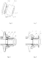
- driving cone discs consisting of a driving movable cone disc 2 and a driving pressing cone disc 1 are mounted on a driving shaft 18, and driven cone discs consisting of a driven movable cone disc 20 and a driven pressing cone disc 21 are mounted on a driven shaft 19 in parallel to the driving shaft 18; the driving cone discs and the driven cone discs clamp a flexible transmission element 12 which can adopt push belts, or metal belts or chains, or V-shaped belts for CVTs.
- the driving pressing cone disc and the driven pressing cone disc keep a connection relationship allowing both slight axial sliding within circa 1mm and mutual rotation on the transmission shaft respectively with the corresponding driving shaft 18 and the driven shaft 19 through the needle bearing 11; the driving movable cone disc and the driven movable cone disc are respectively connected with the driving pressing cone disc and the driven pressing cone disc by splines, ball keys, or any other manner that allow mutual axial sliding without rotation.
- the backs (pressing end surfaces) of the driving pressing cone disc and the driven pressing cone disc are respectively provided with an end surface cam pressing mechanism 3.
- Each end surface cam pressing mechanism consists of a driving cam 3-1 and a driven cam 3-2 which are axially and oppositely arranged.
- the driving cam 3-1 and the driven cam 3-2 can be transmitted by a rolling body or a slope.
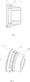
- the axially and oppositely arranged surfaces of the driving cam and the driven cam of the end surface cam pressing mechanism using the rolling body for transmission are respectively provided with six circumferential V-shaped raceways (as shown in Fig.5 ) each of which comprises a forward pressing section 3-3 and a reverse pressing section 3-4 which are interconnected; the raceways of the driving cam and the driven cam correspond to each other; the driving cam and the driven cam are matched with each other by rolling bodies 4 between the corresponding raceways; the six rolling bodies are positioned by a retainer 3-5 (to improve the reliability and assemblability of the system).
- the end surface cam pressing mechanism adopts the pressing principles that the torque is transmitted from the transmission shaft to the end surface cam pressing mechanism, thereby causing relative rotation between the two oppositely arranged end surfaces of the driving cam and the driven cam and the rolling bodies; since the positions of the pressing cone discs are limited by the ratio control movable cone discs and the flexible transmission elements, the driving cam and the driven cam convert torques applied to the operating radius of the rolling bodies into axial force required by friction transmission through their end surfaces and the rolling bodies. According to different directions of the torques, the driving cam and the driven cam achieve forward and reverse pressing through the opposite rotations of the rolling bodies on the forward and reverse pressing sections of the raceways.
- the end surface cam pressing mechanism can at least adopt one of the following four connection manners:
- the disc spring is used as an elastic axial pressing element by the end surface cam pressing mechanism for providing pretension pressing force to the pressing cone disc; besides, in the moment of switching between forward and reverse pressing, the disc spring is used for pressing the two cams tightly so as to prevent the rolling body from being dislocated between the loose cams.
- the end surface cam pressing mechanism using the rolling body for transmission has the advantages of less friction and high sensitivity.
- the axially and oppositely arranged end surfaces of the driving cam 3-1 and the driven cam 3-2 of the end surface cam pressing mechanism using the slope for transmission are respectively provided with two or more circumferential V-shaped pressing surfaces each of which comprises a forward pressing surface 3-3' and a reverse pressing surface 3-4' which are interconnected.
- the pressing principles are similar to those of the end surface cam pressing mechanism using the rolling body for transmission: the driving cam and the driven cam preform forward and reverse pressing according to different directions of the torque through the forward and reverse pressing surfaces.
- the end surface cam pressing mechanism using the slope for transmission has the advantage of simple structure and has the disadvantages of great friction and low sensitivity.
- the ratio control manner of the ratio control system of the CVT with cone discs is changed from controlling the axial sliding of only the driving movable cone disc to control the synchronous rotation of the driving movable cone disc and the driven movable cone disc.
- the hollow screw 7 and the nut 6 which are matched each other are arranged on the back of the driving movable cone disc 2
- the hollow screw 23 and the nut 22 which are matched each other are arranged on the back of the driven movable cone disc 20
- the driving shaft and the driven shaft are respectively placed in the hollow screws
- the hollow screws and the nuts adopt ball screw structures
- the hollow screws 7 and 23 are respectively connected with their corresponding driving movable cone disc and driven movable cone disc via bearings capable of bearing axial and radial loads, and directly connected with corresponding driving shafts and driven shafts
- the nuts are connected with corresponding driving shafts and driven shafts through bearings capable of bearing axial and radial loads, with ratio control gears 8 arranged on the outer walls of the nuts.
- the hollow screws and nuts can be connected in a rolling screw manner (not shown) with intermediate rolling bodies (such as balls), compared with an ordinary sliding screw connection manner, the rolling screw manner can reduce the torque required for ratio control, prolong the service life of screws and reduce requirements for performance of the ratio control motor.
- the rolling bodies between the hollow screws and nuts only slide in the raceways between the hollow screws and nuts; in order to ensure the ratio control distance of the ratio control mechanism and the rotation space of the rolling bodies, the effective operating length of the raceways between the hollow screws and nuts should be greater than the total length of all the rolling bodies.
- the hollow screws are connected with the transmission housing of the CVT by stopping pins (not shown) or other structures, mechanisms or parts, which can prevent rotation, but do not generate axial loads or axial positioning, to enclose the axial force of ratio control in the transmission shaft, so that the loads cannot be transmitted to the transmission housing of the CVT with relative-low strength, and cannot rotate with the ratio control mechanism; therefore, not only can a ratio control function be achieved, but also the effect of ratio control force on the transmission housing of the CVT is eliminated, improving reliability.
- a rotational speed sensor 13 and a rotational speed signal generating device 14 can be arranged at appropriate positions respectively corresponding to the driving shaft and the driven shaft on the transmission housing of the CVT.
- the transmission housing of the CVT can also be provided with an angular displacement sensor 15 for measuring the sliding positions of the cone discs, and the probe (not shown) of the angular displacement sensor is connected with circumferential rolling grooves (not shown) formed in the nuts.
- ridged stopper mechanisms a16 can also be arranged on the ratio control gears 8 of the nut 6, and stopper mechanisms b17 matched with the stopper mechanisms a16 are arranged at the corresponding positions on the housing; when the axial sliding of the ratio control movable cone disc goes beyond the limit positions at two ends, the ratio control nuts cannot rotate any more under the actions of the stopper mechanisms a16 and the stopper mechanisms b17, so that safe operation of the ratio control mechanism is guaranteed.
Landscapes
- Engineering & Computer Science (AREA)
- General Engineering & Computer Science (AREA)
- Mechanical Engineering (AREA)
- Transmissions By Endless Flexible Members (AREA)
- Friction Gearing (AREA)
Applications Claiming Priority (3)
| Application Number | Priority Date | Filing Date | Title |
|---|---|---|---|
| CN201410106539.5A CN103867678B (zh) | 2014-03-20 | 2014-03-20 | 一种锥盘式无级变速器 |
| CN201420129364.5U CN203770563U (zh) | 2014-03-20 | 2014-03-20 | 一种锥盘式无级变速器 |
| PCT/CN2014/095737 WO2015139502A1 (fr) | 2014-03-20 | 2014-12-31 | Transmission à variation continue de type à disques biseautés |
Publications (3)
| Publication Number | Publication Date |
|---|---|
| EP3128207A1 true EP3128207A1 (fr) | 2017-02-08 |
| EP3128207A4 EP3128207A4 (fr) | 2017-12-13 |
| EP3128207B1 EP3128207B1 (fr) | 2019-12-04 |
Family
ID=54143749
Family Applications (1)
| Application Number | Title | Priority Date | Filing Date |
|---|---|---|---|
| EP14886159.4A Not-in-force EP3128207B1 (fr) | 2014-03-20 | 2014-12-31 | Transmission à variation continue de type à disques biseautés |
Country Status (4)
| Country | Link |
|---|---|
| US (1) | US10024404B2 (fr) |
| EP (1) | EP3128207B1 (fr) |
| JP (1) | JP6507225B2 (fr) |
| WO (1) | WO2015139502A1 (fr) |
Cited By (1)
| Publication number | Priority date | Publication date | Assignee | Title |
|---|---|---|---|---|
| CN110762173A (zh) * | 2018-07-25 | 2020-02-07 | 杭州肇鹏科技有限公司 | 一种齿轮传动的三轴调速锥盘式无级变速器 |
Families Citing this family (4)
| Publication number | Priority date | Publication date | Assignee | Title |
|---|---|---|---|---|
| US10385951B2 (en) | 2017-10-04 | 2019-08-20 | Schaeffler Technologies AG & Co. KG | Electric axle assembly |
| CN111188881B (zh) * | 2020-02-10 | 2021-05-11 | 淮阴工学院 | 一种三轮小车 |
| US11590413B2 (en) | 2020-07-08 | 2023-02-28 | Nintendo Co., Ltd. | Storage medium storing information processing program with changeable operation modes, information processing apparatus, information processing system, and information processing method |
| CN114992295B (zh) * | 2022-07-05 | 2025-09-09 | 常州东风无级变速器有限公司 | 长寿命耐冲击的凸轮加压机构及无级变速器 |
Family Cites Families (27)
| Publication number | Priority date | Publication date | Assignee | Title |
|---|---|---|---|---|
| US3279270A (en) * | 1964-06-08 | 1966-10-18 | Eaton Mfg Co | Pulley apparatus |
| US3616706A (en) * | 1968-05-18 | 1971-11-02 | Yamaha Motor Co Ltd | Transmission device of a sheave drive type |
| DE2016181B2 (de) * | 1970-04-04 | 1971-09-09 | PIV Antrieb Werner Reimers KG, 6380 Bad Homburg | Lagerung fuer die kegelscheiben eines kegelscheiben umschling ungsgetriebes |
| US3699827A (en) * | 1971-07-09 | 1972-10-24 | Hilmar Vogel | Axial actuator and force control for rotary members, especially variable speed drives |
| US4026161A (en) * | 1974-06-24 | 1977-05-31 | Hilmar Vogel | Variable speed transmission and actuator therefor |
| DE2734630C2 (de) * | 1977-08-01 | 1981-02-05 | Hilmar 8033 Krailling Vogel | Zweisträngiges stufenlos einstellbares Kegelscheibenumschlingungsgetriebe mit gleichmäßiger Lastverteilung |
| DE3028490C2 (de) | 1980-07-26 | 1983-01-13 | P.I.V. Antrieb Werner Reimers GmbH & Co KG, 6380 Bad Homburg | Stufenlos einstellbares Kegelscheibengetriebe |
| JPS6026842A (ja) * | 1983-07-21 | 1985-02-09 | Aisin Warner Ltd | Vベルト式無段変速機 |
| JPH0743012B2 (ja) * | 1985-07-10 | 1995-05-15 | アイシン・エィ・ダブリュ株式会社 | Vベルト式無段変速機 |
| DE4036683B4 (de) | 1989-11-21 | 2008-05-29 | Luk Lamellen Und Kupplungsbau Beteiligungs Kg | Stufenlos einstellbares Kegelscheibenumschlingungsgetriebe |
| US5184981A (en) * | 1991-01-07 | 1993-02-09 | Wittke Ernest C | Cam loaded continuously variable transmission |
| CN2254971Y (zh) | 1995-09-12 | 1997-05-28 | 张宝忠 | 排片链式机械无级变速器 |
| JPH10184840A (ja) | 1996-12-27 | 1998-07-14 | Honda Motor Co Ltd | 無段変速機 |
| DE19921750B4 (de) * | 1998-05-18 | 2012-03-08 | Schaeffler Technologies Gmbh & Co. Kg | Getriebe |
| US6406390B1 (en) * | 1999-09-24 | 2002-06-18 | Borgwarner Automotive, Inc. | Continuously variable belt drive system |
| US6379274B1 (en) * | 1999-11-29 | 2002-04-30 | Cvtech R & D Inc. | Driven pulley |
| US6743129B1 (en) * | 1999-11-29 | 2004-06-01 | Team Industries, Inc. | Clutch with no relative rotation |
| DE10139119A1 (de) | 2000-09-08 | 2002-03-21 | Luk Lamellen & Kupplungsbau | Drehmomentenfühler |
| JP4674979B2 (ja) * | 2001-02-23 | 2011-04-20 | 川崎重工業株式会社 | 不整地走行車のvベルト式無段変速機 |
| US20040063524A1 (en) * | 2002-10-01 | 2004-04-01 | Arctic Cat, Inc. | Dual cam surface clutch |
| DE112007000502A5 (de) | 2006-03-24 | 2008-11-27 | Luk Lamellen Und Kupplungsbau Beteiligungs Kg | Drehmomentfühlvorrichtung für ein Kegelscheibenumschlingsungsgetriebe |
| DE102006018806A1 (de) | 2006-04-22 | 2007-10-25 | Luk Lamellen Und Kupplungsbau Beteiligungs Kg | CVT mit Leistungsverzweigung, insbesondere für Nutzfahrzeuge |
| CN201344234Y (zh) | 2008-12-29 | 2009-11-11 | 重庆工学院 | 自动加压无偏斜金属带式汽车无级变速器 |
| CN201875074U (zh) | 2010-11-24 | 2011-06-22 | 程乃士 | 智能加压无级变速器 |
| CN102278436B (zh) | 2011-07-11 | 2014-03-05 | 程乃士 | 无级变速器 |
| CN203770563U (zh) | 2014-03-20 | 2014-08-13 | 程乃士 | 一种锥盘式无级变速器 |
| CN103867678B (zh) * | 2014-03-20 | 2016-05-18 | 程乃士 | 一种锥盘式无级变速器 |
-
2014
- 2014-12-31 US US15/127,278 patent/US10024404B2/en active Active
- 2014-12-31 JP JP2017500112A patent/JP6507225B2/ja not_active Expired - Fee Related
- 2014-12-31 WO PCT/CN2014/095737 patent/WO2015139502A1/fr not_active Ceased
- 2014-12-31 EP EP14886159.4A patent/EP3128207B1/fr not_active Not-in-force
Cited By (1)
| Publication number | Priority date | Publication date | Assignee | Title |
|---|---|---|---|---|
| CN110762173A (zh) * | 2018-07-25 | 2020-02-07 | 杭州肇鹏科技有限公司 | 一种齿轮传动的三轴调速锥盘式无级变速器 |
Also Published As
| Publication number | Publication date |
|---|---|
| EP3128207A4 (fr) | 2017-12-13 |
| EP3128207B1 (fr) | 2019-12-04 |
| JP6507225B2 (ja) | 2019-04-24 |
| US20170159777A1 (en) | 2017-06-08 |
| WO2015139502A1 (fr) | 2015-09-24 |
| US10024404B2 (en) | 2018-07-17 |
| JP2017508938A (ja) | 2017-03-30 |
Similar Documents
| Publication | Publication Date | Title |
|---|---|---|
| CN103867678B (zh) | 一种锥盘式无级变速器 | |
| EP3792516B1 (fr) | Embrayage à blocage d'entrée inverse et actionneur | |
| US8827856B1 (en) | Infinitely variable transmission with an IVT stator controlling assembly | |
| EP3128207B1 (fr) | Transmission à variation continue de type à disques biseautés | |
| US8382636B2 (en) | Continuously variable transmission | |
| CN100540935C (zh) | 无级齿啮合控制型离合器 | |
| WO2021110154A1 (fr) | Transmission automatique intelligente auto-adaptative | |
| CN105840755A (zh) | 一种环布双锥台摩擦式无级自动变速装置 | |
| JP5646075B2 (ja) | スマート加圧式無段変速機 | |
| CN203770563U (zh) | 一种锥盘式无级变速器 | |
| EP2754921A2 (fr) | Dispositif de transmission à variation continue (cvt) commandée par un moteur réducteur | |
| WO2013007186A1 (fr) | Transmission à variation continue économique et permettant d'économiser l'énergie | |
| CN103089969A (zh) | 一种消除齿侧间隙的双向传动齿轮 | |
| US3516305A (en) | Torque converter | |
| RU2445529C1 (ru) | Планетарная передача | |
| CN102245932A (zh) | 摩擦轮式无级变速装置 | |
| CN106801725A (zh) | 一种实现轴系快速正反转的机械装置 | |
| CN205371498U (zh) | 一种用电机控制机械传动调速的金属带式无级变速器 | |
| CN118128871A (zh) | 一种螺纹式无级变速器及其单级式、两级式无级变速器组 | |
| CN108006185B (zh) | 直线和/或旋转运动执行机构 | |
| CN103195909A (zh) | 锥面同步啮合齿轮 | |
| CN108533700B (zh) | 一种无级变速器 | |
| CN203770564U (zh) | 轴交角可变的变径式摩擦无级变速装置 | |
| CN2679423Y (zh) | 空心滚子轴承行星减速器 | |
| CN220168474U (zh) | 一种螺纹式无级变速器及其单级式、两级式无级变速器组 |
Legal Events
| Date | Code | Title | Description |
|---|---|---|---|
| STAA | Information on the status of an ep patent application or granted ep patent |
Free format text: STATUS: THE INTERNATIONAL PUBLICATION HAS BEEN MADE |
|
| PUAI | Public reference made under article 153(3) epc to a published international application that has entered the european phase |
Free format text: ORIGINAL CODE: 0009012 |
|
| STAA | Information on the status of an ep patent application or granted ep patent |
Free format text: STATUS: REQUEST FOR EXAMINATION WAS MADE |
|
| 17P | Request for examination filed |
Effective date: 20161018 |
|
| AK | Designated contracting states |
Kind code of ref document: A1 Designated state(s): AL AT BE BG CH CY CZ DE DK EE ES FI FR GB GR HR HU IE IS IT LI LT LU LV MC MK MT NL NO PL PT RO RS SE SI SK SM TR |
|
| AX | Request for extension of the european patent |
Extension state: BA ME |
|
| DAX | Request for extension of the european patent (deleted) | ||
| A4 | Supplementary search report drawn up and despatched |
Effective date: 20171114 |
|
| RIC1 | Information provided on ipc code assigned before grant |
Ipc: F16H 25/20 20060101ALI20171108BHEP Ipc: F16H 37/00 20060101AFI20171108BHEP Ipc: F16H 63/06 20060101ALI20171108BHEP |
|
| STAA | Information on the status of an ep patent application or granted ep patent |
Free format text: STATUS: EXAMINATION IS IN PROGRESS |
|
| 17Q | First examination report despatched |
Effective date: 20190103 |
|
| GRAP | Despatch of communication of intention to grant a patent |
Free format text: ORIGINAL CODE: EPIDOSNIGR1 |
|
| STAA | Information on the status of an ep patent application or granted ep patent |
Free format text: STATUS: GRANT OF PATENT IS INTENDED |
|
| INTG | Intention to grant announced |
Effective date: 20190704 |
|
| GRAS | Grant fee paid |
Free format text: ORIGINAL CODE: EPIDOSNIGR3 |
|
| GRAA | (expected) grant |
Free format text: ORIGINAL CODE: 0009210 |
|
| STAA | Information on the status of an ep patent application or granted ep patent |
Free format text: STATUS: THE PATENT HAS BEEN GRANTED |
|
| AK | Designated contracting states |
Kind code of ref document: B1 Designated state(s): AL AT BE BG CH CY CZ DE DK EE ES FI FR GB GR HR HU IE IS IT LI LT LU LV MC MK MT NL NO PL PT RO RS SE SI SK SM TR |
|
| REG | Reference to a national code |
Ref country code: GB Ref legal event code: FG4D |
|
| REG | Reference to a national code |
Ref country code: CH Ref legal event code: EP |
|
| REG | Reference to a national code |
Ref country code: AT Ref legal event code: REF Ref document number: 1209816 Country of ref document: AT Kind code of ref document: T Effective date: 20191215 |
|
| REG | Reference to a national code |
Ref country code: DE Ref legal event code: R096 Ref document number: 602014058062 Country of ref document: DE |
|
| REG | Reference to a national code |
Ref country code: IE Ref legal event code: FG4D |
|
| RAP2 | Party data changed (patent owner data changed or rights of a patent transferred) |
Owner name: CHANGZHOU DONGFENG CONTINUOUSLY VARIABLE TRANSMISSION CO., LTD. |
|
| REG | Reference to a national code |
Ref country code: NL Ref legal event code: MP Effective date: 20191204 |
|
| REG | Reference to a national code |
Ref country code: LT Ref legal event code: MG4D |
|
| PG25 | Lapsed in a contracting state [announced via postgrant information from national office to epo] |
Ref country code: SE Free format text: LAPSE BECAUSE OF FAILURE TO SUBMIT A TRANSLATION OF THE DESCRIPTION OR TO PAY THE FEE WITHIN THE PRESCRIBED TIME-LIMIT Effective date: 20191204 Ref country code: LV Free format text: LAPSE BECAUSE OF FAILURE TO SUBMIT A TRANSLATION OF THE DESCRIPTION OR TO PAY THE FEE WITHIN THE PRESCRIBED TIME-LIMIT Effective date: 20191204 Ref country code: BG Free format text: LAPSE BECAUSE OF FAILURE TO SUBMIT A TRANSLATION OF THE DESCRIPTION OR TO PAY THE FEE WITHIN THE PRESCRIBED TIME-LIMIT Effective date: 20200304 Ref country code: FI Free format text: LAPSE BECAUSE OF FAILURE TO SUBMIT A TRANSLATION OF THE DESCRIPTION OR TO PAY THE FEE WITHIN THE PRESCRIBED TIME-LIMIT Effective date: 20191204 Ref country code: NO Free format text: LAPSE BECAUSE OF FAILURE TO SUBMIT A TRANSLATION OF THE DESCRIPTION OR TO PAY THE FEE WITHIN THE PRESCRIBED TIME-LIMIT Effective date: 20200304 Ref country code: LT Free format text: LAPSE BECAUSE OF FAILURE TO SUBMIT A TRANSLATION OF THE DESCRIPTION OR TO PAY THE FEE WITHIN THE PRESCRIBED TIME-LIMIT Effective date: 20191204 |
|
| PG25 | Lapsed in a contracting state [announced via postgrant information from national office to epo] |
Ref country code: HR Free format text: LAPSE BECAUSE OF FAILURE TO SUBMIT A TRANSLATION OF THE DESCRIPTION OR TO PAY THE FEE WITHIN THE PRESCRIBED TIME-LIMIT Effective date: 20191204 Ref country code: RS Free format text: LAPSE BECAUSE OF FAILURE TO SUBMIT A TRANSLATION OF THE DESCRIPTION OR TO PAY THE FEE WITHIN THE PRESCRIBED TIME-LIMIT Effective date: 20191204 |
|
| PG25 | Lapsed in a contracting state [announced via postgrant information from national office to epo] |
Ref country code: AL Free format text: LAPSE BECAUSE OF FAILURE TO SUBMIT A TRANSLATION OF THE DESCRIPTION OR TO PAY THE FEE WITHIN THE PRESCRIBED TIME-LIMIT Effective date: 20191204 |
|
| PG25 | Lapsed in a contracting state [announced via postgrant information from national office to epo] |
Ref country code: CZ Free format text: LAPSE BECAUSE OF FAILURE TO SUBMIT A TRANSLATION OF THE DESCRIPTION OR TO PAY THE FEE WITHIN THE PRESCRIBED TIME-LIMIT Effective date: 20191204 Ref country code: RO Free format text: LAPSE BECAUSE OF FAILURE TO SUBMIT A TRANSLATION OF THE DESCRIPTION OR TO PAY THE FEE WITHIN THE PRESCRIBED TIME-LIMIT Effective date: 20191204 Ref country code: ES Free format text: LAPSE BECAUSE OF FAILURE TO SUBMIT A TRANSLATION OF THE DESCRIPTION OR TO PAY THE FEE WITHIN THE PRESCRIBED TIME-LIMIT Effective date: 20191204 Ref country code: NL Free format text: LAPSE BECAUSE OF FAILURE TO SUBMIT A TRANSLATION OF THE DESCRIPTION OR TO PAY THE FEE WITHIN THE PRESCRIBED TIME-LIMIT Effective date: 20191204 Ref country code: EE Free format text: LAPSE BECAUSE OF FAILURE TO SUBMIT A TRANSLATION OF THE DESCRIPTION OR TO PAY THE FEE WITHIN THE PRESCRIBED TIME-LIMIT Effective date: 20191204 Ref country code: PT Free format text: LAPSE BECAUSE OF FAILURE TO SUBMIT A TRANSLATION OF THE DESCRIPTION OR TO PAY THE FEE WITHIN THE PRESCRIBED TIME-LIMIT Effective date: 20200429 |
|
| REG | Reference to a national code |
Ref country code: CH Ref legal event code: PL |
|
| REG | Reference to a national code |
Ref country code: BE Ref legal event code: MM Effective date: 20191231 |
|
| PG25 | Lapsed in a contracting state [announced via postgrant information from national office to epo] |
Ref country code: IS Free format text: LAPSE BECAUSE OF FAILURE TO SUBMIT A TRANSLATION OF THE DESCRIPTION OR TO PAY THE FEE WITHIN THE PRESCRIBED TIME-LIMIT Effective date: 20200404 Ref country code: SK Free format text: LAPSE BECAUSE OF FAILURE TO SUBMIT A TRANSLATION OF THE DESCRIPTION OR TO PAY THE FEE WITHIN THE PRESCRIBED TIME-LIMIT Effective date: 20191204 Ref country code: SM Free format text: LAPSE BECAUSE OF FAILURE TO SUBMIT A TRANSLATION OF THE DESCRIPTION OR TO PAY THE FEE WITHIN THE PRESCRIBED TIME-LIMIT Effective date: 20191204 |
|
| REG | Reference to a national code |
Ref country code: DE Ref legal event code: R097 Ref document number: 602014058062 Country of ref document: DE |
|
| REG | Reference to a national code |
Ref country code: AT Ref legal event code: MK05 Ref document number: 1209816 Country of ref document: AT Kind code of ref document: T Effective date: 20191204 |
|
| PG25 | Lapsed in a contracting state [announced via postgrant information from national office to epo] |
Ref country code: MC Free format text: LAPSE BECAUSE OF FAILURE TO SUBMIT A TRANSLATION OF THE DESCRIPTION OR TO PAY THE FEE WITHIN THE PRESCRIBED TIME-LIMIT Effective date: 20191204 |
|
| PLBE | No opposition filed within time limit |
Free format text: ORIGINAL CODE: 0009261 |
|
| STAA | Information on the status of an ep patent application or granted ep patent |
Free format text: STATUS: NO OPPOSITION FILED WITHIN TIME LIMIT |
|
| PG25 | Lapsed in a contracting state [announced via postgrant information from national office to epo] |
Ref country code: DK Free format text: LAPSE BECAUSE OF FAILURE TO SUBMIT A TRANSLATION OF THE DESCRIPTION OR TO PAY THE FEE WITHIN THE PRESCRIBED TIME-LIMIT Effective date: 20191204 Ref country code: IE Free format text: LAPSE BECAUSE OF NON-PAYMENT OF DUE FEES Effective date: 20191231 Ref country code: LU Free format text: LAPSE BECAUSE OF NON-PAYMENT OF DUE FEES Effective date: 20191231 |
|
| 26N | No opposition filed |
Effective date: 20200907 |
|
| PG25 | Lapsed in a contracting state [announced via postgrant information from national office to epo] |
Ref country code: LI Free format text: LAPSE BECAUSE OF NON-PAYMENT OF DUE FEES Effective date: 20191231 Ref country code: SI Free format text: LAPSE BECAUSE OF FAILURE TO SUBMIT A TRANSLATION OF THE DESCRIPTION OR TO PAY THE FEE WITHIN THE PRESCRIBED TIME-LIMIT Effective date: 20191204 Ref country code: CH Free format text: LAPSE BECAUSE OF NON-PAYMENT OF DUE FEES Effective date: 20191231 Ref country code: AT Free format text: LAPSE BECAUSE OF FAILURE TO SUBMIT A TRANSLATION OF THE DESCRIPTION OR TO PAY THE FEE WITHIN THE PRESCRIBED TIME-LIMIT Effective date: 20191204 Ref country code: BE Free format text: LAPSE BECAUSE OF NON-PAYMENT OF DUE FEES Effective date: 20191231 Ref country code: PL Free format text: LAPSE BECAUSE OF FAILURE TO SUBMIT A TRANSLATION OF THE DESCRIPTION OR TO PAY THE FEE WITHIN THE PRESCRIBED TIME-LIMIT Effective date: 20191204 |
|
| PG25 | Lapsed in a contracting state [announced via postgrant information from national office to epo] |
Ref country code: IT Free format text: LAPSE BECAUSE OF FAILURE TO SUBMIT A TRANSLATION OF THE DESCRIPTION OR TO PAY THE FEE WITHIN THE PRESCRIBED TIME-LIMIT Effective date: 20191204 |
|
| GBPC | Gb: european patent ceased through non-payment of renewal fee |
Effective date: 20200304 |
|
| PG25 | Lapsed in a contracting state [announced via postgrant information from national office to epo] |
Ref country code: GB Free format text: LAPSE BECAUSE OF NON-PAYMENT OF DUE FEES Effective date: 20200304 |
|
| PG25 | Lapsed in a contracting state [announced via postgrant information from national office to epo] |
Ref country code: CY Free format text: LAPSE BECAUSE OF FAILURE TO SUBMIT A TRANSLATION OF THE DESCRIPTION OR TO PAY THE FEE WITHIN THE PRESCRIBED TIME-LIMIT Effective date: 20191204 |
|
| PG25 | Lapsed in a contracting state [announced via postgrant information from national office to epo] |
Ref country code: GR Free format text: LAPSE BECAUSE OF FAILURE TO SUBMIT A TRANSLATION OF THE DESCRIPTION OR TO PAY THE FEE WITHIN THE PRESCRIBED TIME-LIMIT Effective date: 20191204 |
|
| PG25 | Lapsed in a contracting state [announced via postgrant information from national office to epo] |
Ref country code: MT Free format text: LAPSE BECAUSE OF FAILURE TO SUBMIT A TRANSLATION OF THE DESCRIPTION OR TO PAY THE FEE WITHIN THE PRESCRIBED TIME-LIMIT Effective date: 20191204 Ref country code: HU Free format text: LAPSE BECAUSE OF FAILURE TO SUBMIT A TRANSLATION OF THE DESCRIPTION OR TO PAY THE FEE WITHIN THE PRESCRIBED TIME-LIMIT; INVALID AB INITIO Effective date: 20141231 |
|
| PG25 | Lapsed in a contracting state [announced via postgrant information from national office to epo] |
Ref country code: TR Free format text: LAPSE BECAUSE OF FAILURE TO SUBMIT A TRANSLATION OF THE DESCRIPTION OR TO PAY THE FEE WITHIN THE PRESCRIBED TIME-LIMIT Effective date: 20191204 |
|
| PG25 | Lapsed in a contracting state [announced via postgrant information from national office to epo] |
Ref country code: MK Free format text: LAPSE BECAUSE OF FAILURE TO SUBMIT A TRANSLATION OF THE DESCRIPTION OR TO PAY THE FEE WITHIN THE PRESCRIBED TIME-LIMIT Effective date: 20191204 |
|
| PGFP | Annual fee paid to national office [announced via postgrant information from national office to epo] |
Ref country code: FR Payment date: 20221222 Year of fee payment: 9 |
|
| PGFP | Annual fee paid to national office [announced via postgrant information from national office to epo] |
Ref country code: DE Payment date: 20221229 Year of fee payment: 9 |
|
| REG | Reference to a national code |
Ref country code: DE Ref legal event code: R119 Ref document number: 602014058062 Country of ref document: DE |
|
| PG25 | Lapsed in a contracting state [announced via postgrant information from national office to epo] |
Ref country code: DE Free format text: LAPSE BECAUSE OF NON-PAYMENT OF DUE FEES Effective date: 20240702 |
|
| PG25 | Lapsed in a contracting state [announced via postgrant information from national office to epo] |
Ref country code: FR Free format text: LAPSE BECAUSE OF NON-PAYMENT OF DUE FEES Effective date: 20231231 |
|
| PG25 | Lapsed in a contracting state [announced via postgrant information from national office to epo] |
Ref country code: FR Free format text: LAPSE BECAUSE OF NON-PAYMENT OF DUE FEES Effective date: 20231231 Ref country code: DE Free format text: LAPSE BECAUSE OF NON-PAYMENT OF DUE FEES Effective date: 20240702 |