EP3128252A1 - Wärmepumpensystem - Google Patents
Wärmepumpensystem Download PDFInfo
- Publication number
- EP3128252A1 EP3128252A1 EP15180162.8A EP15180162A EP3128252A1 EP 3128252 A1 EP3128252 A1 EP 3128252A1 EP 15180162 A EP15180162 A EP 15180162A EP 3128252 A1 EP3128252 A1 EP 3128252A1
- Authority
- EP
- European Patent Office
- Prior art keywords
- heat exchanger
- air
- casing
- pump system
- evaporator heat
- Prior art date
- Legal status (The legal status is an assumption and is not a legal conclusion. Google has not performed a legal analysis and makes no representation as to the accuracy of the status listed.)
- Withdrawn
Links
Images

Classifications
-
- F—MECHANICAL ENGINEERING; LIGHTING; HEATING; WEAPONS; BLASTING
- F24—HEATING; RANGES; VENTILATING
- F24F—AIR-CONDITIONING; AIR-HUMIDIFICATION; VENTILATION; USE OF AIR CURRENTS FOR SCREENING
- F24F1/00—Room units for air-conditioning, e.g. separate or self-contained units or units receiving primary air from a central station
- F24F1/02—Self-contained room units for air-conditioning, i.e. with all apparatus for treatment installed in a common casing
- F24F1/032—Self-contained room units for air-conditioning, i.e. with all apparatus for treatment installed in a common casing characterised by heat exchangers
-
- F—MECHANICAL ENGINEERING; LIGHTING; HEATING; WEAPONS; BLASTING
- F24—HEATING; RANGES; VENTILATING
- F24H—FLUID HEATERS, e.g. WATER OR AIR HEATERS, HAVING HEAT-GENERATING MEANS, e.g. HEAT PUMPS, IN GENERAL
- F24H4/00—Fluid heaters characterised by the use of heat pumps
- F24H4/02—Water heaters
- F24H4/04—Storage heaters
-
- F—MECHANICAL ENGINEERING; LIGHTING; HEATING; WEAPONS; BLASTING
- F24—HEATING; RANGES; VENTILATING
- F24F—AIR-CONDITIONING; AIR-HUMIDIFICATION; VENTILATION; USE OF AIR CURRENTS FOR SCREENING
- F24F5/00—Air-conditioning systems or apparatus not covered by F24F1/00 or F24F3/00, e.g. using solar heat or combined with household units such as an oven or water heater
- F24F5/0096—Air-conditioning systems or apparatus not covered by F24F1/00 or F24F3/00, e.g. using solar heat or combined with household units such as an oven or water heater combined with domestic apparatus
-
- F—MECHANICAL ENGINEERING; LIGHTING; HEATING; WEAPONS; BLASTING
- F24—HEATING; RANGES; VENTILATING
- F24H—FLUID HEATERS, e.g. WATER OR AIR HEATERS, HAVING HEAT-GENERATING MEANS, e.g. HEAT PUMPS, IN GENERAL
- F24H9/00—Details
- F24H9/0005—Details for water heaters
- F24H9/001—Guiding means
-
- F—MECHANICAL ENGINEERING; LIGHTING; HEATING; WEAPONS; BLASTING
- F25—REFRIGERATION OR COOLING; COMBINED HEATING AND REFRIGERATION SYSTEMS; HEAT PUMP SYSTEMS; MANUFACTURE OR STORAGE OF ICE; LIQUEFACTION SOLIDIFICATION OF GASES
- F25B—REFRIGERATION MACHINES, PLANTS OR SYSTEMS; COMBINED HEATING AND REFRIGERATION SYSTEMS; HEAT PUMP SYSTEMS
- F25B2339/00—Details of evaporators; Details of condensers
- F25B2339/04—Details of condensers
- F25B2339/047—Water-cooled condensers
-
- F—MECHANICAL ENGINEERING; LIGHTING; HEATING; WEAPONS; BLASTING
- F25—REFRIGERATION OR COOLING; COMBINED HEATING AND REFRIGERATION SYSTEMS; HEAT PUMP SYSTEMS; MANUFACTURE OR STORAGE OF ICE; LIQUEFACTION SOLIDIFICATION OF GASES
- F25B—REFRIGERATION MACHINES, PLANTS OR SYSTEMS; COMBINED HEATING AND REFRIGERATION SYSTEMS; HEAT PUMP SYSTEMS
- F25B2400/00—Component parts or details not otherwise provided for in this subclass
- F25B2400/12—Inflammable refrigerants
- F25B2400/121—Inflammable refrigerants using R1234
Definitions
- the present invention relates to a heat pump system having a refrigerant circuit employing ducted air as exchange medium.
- HVAC home heating, ventilating and air conditioning
- HFCs hydrofluorocarbons
- CFCs chlorofluorocarbons
- PFCs perfluorocarbons
- Fig. 3 discloses a conventional heat pump type water heater system.
- the system has a casing enclosing a refrigerant circuit and a water tank 97 disposed below the casing.
- the refrigerant circuit includes a compressor 91 compressing refrigerant to obtain refrigerant of high temperature and high pressure, a condenser heat exchanger 92 condensing the refrigerant of high temperature and high pressure to release heat from the refrigerant to the water to be entering the water tank 97, an expansion valve (now shown) depressurizing the high-pressure refrigerant that is condensed by the condenser heat exchanger 92, and an evaporator heat exchanger 93 evaporating the refrigerant that is depressurized by the expansion valve to absorb heat from air that is supplied via a fan 94.
- An electronic board 95 is also enclosed in the casing.
- An air inlet duct 961 and an air outlet duct 962 are connected with the casing to respectively introduce and
- a heat pump system including a casing defining an air inlet, a refrigerant circuit disposed in the casing and having an evaporator heat exchanger for vaporizing refrigerant, a fan associated with the evaporator heat exchanger adapted for being operable to introduce air into the casing via the air inlet and further passes through the evaporator heat exchanger, and an internal air directing means.
- the air directing means is disposed between the air inlet and the evaporator heat exchanger. In this way, the air flow introduced into the casing can reach the evaporator heat exchanger without contacting components within the space where the air directing means is positioned, thereby reducing the possibility of explosion caused by electrostatic charges and/or heat losses.
- the air directing means includes a nozzle defining an air passageway therein to direct air flow from the air inlet to the evaporator heat exchanger without contacting other components.
- the nozzle has an incoming portion with an incoming surface facing the air inlet, an outgoing portion with an outgoing surface facing the evaporator heat exchanger, and an intermediate portion connected between the incoming portion and the outgoing portion.
- the intermediate portion has a cross-sectional size that is smaller than a size of the outgoing surface to adapt it to be contained in a compact space within the casing.
- the cross-sectional size of the intermediate portion is smaller than a size of the incoming surface.
- the intermediate portion is bended so as to prevent it from interfering with other components.
- the casing defines an air outlet; and wherein the evaporator heat exchanger and the fan are both encased between the air directing means and the air outlet, so that air flow can pass through the evaporator heat exchanger and the fan and be discharged outside of the casing without contacting other components.
- the refrigerant circuit is charged with a flammable refrigerant or combined refrigerants containing a flammable refrigerant.
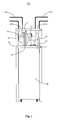
- a heat pump system 100 takes form of a domestic hot water tank integrated with a heat pump for preparing domestic hot water.
- the heat pump system 100 can stand on the floor with a water tank 40 located at a lower portion thereof and a refrigerant circuit located at an upper portion thereof.
- the water tank is enclosed by top, bottom, and side insulations to avoid a heat loss of hot water inside the tank 40.
- the refrigerant circuit is enclosed by a casing composed by top, side, and bottom insulated walls 11, 12, 13 for reducing heat loss on operation of the refrigerant circuit.
- An air inlet duct 141 and an air outlet duct 142 are connected with the casing to define an air inlet 1411 and an air outlet 1421 respectively.
- the air inlet 1411 and the air outlet 1421 can be disposed in the same wall, like the top wall 11, or respectively in two different walls, like the top wall 11 and the side wall 12.
- the refrigerant circuit typically has a compressor 21, a condenser heat exchanger 22, an expansion device (now shown), and an evaporator heat exchanger 23. These components are generally serially connected via conduits and are well known in the art.
- the compressor 21 acts on relatively cool gaseous refrigerant to raise the temperature and pressure of the refrigerant. From the compressor 21, the high temperature, high pressure gaseous refrigerant flows into the condenser heat exchanger 22 where it is cooled and exits the condenser heat exchanger 22 as a high pressure liquid refrigerant.
- the condenser heat exchanger 22 can be a plate type heat exchanger, and it performs as a heat source for the water tank 40. Water extracted from the water tank 40 passes through the condenser heat exchanger 22 to be heated by the refrigerant in a non-contact way, and then the heated water flows back and is stored within the tank 40.
- the evaporator heat exchanger 23 takes form of a finned tube heat exchanger.
- the finned tube heat exchanger typically has copper tube coils 233 that are accompanied by aluminum fins for purpose of maximizing heat transfer between the refrigerant and air mediums.
- the heat exchanger 23 is encased in a shell with a front face 231 and a rear face 232.
- a centrifugal fan 24 is disposed adjacent to the evaporator heat exchanger 23 for being operable to generate forced air passing through tube coils and fins of the evaporator heat exchanger 23.
- the fan 24 is preferably housed in a housing 241 with one opening connected to the rear face 232 of the evaporator heat exchanger 23 and the other opening connected to the air outlet 1421 of the casing.
- the low temperature refrigerant absorbs heat from air blown over the tube coils 233 and the fins, and exits the appliance via the air outlet duct 142.
- the suction of the compressor 21 then draws the gaseous refrigerant back to the compressor where the cycle begins again.
- an electronic board 25 is contained in the casing and connected with related components, such as the compressor 21 and the fan 24 to control the operation of the refrigerant circuit.
- the refrigerant circuit is charged with a flammable refrigerant or combined refrigerants containing a flammable refrigerant.
- the flammable refrigerant can be HFC or HC substance such as R32, R152a, R290, R600 and the like.
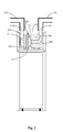
- an air directing means 26 is disposed in the casing and located between the air inlet 1411 and the evaporator heat exchanger 23.
- the air directing means 26 can take form of a nozzle that defines an air passageway therein to direct air flow from the air inlet 1411 to the evaporator heat exchanger 23 without contacting other components, thereby reducing the possibility of explosion caused by electrostatic charges and heat losses.
- the nozzle has an incoming portion 261 with an incoming surface facing the air inlet 1411, an outgoing portion 263 with an outgoing surface facing the front face 231 of the evaporator heat exchanger 23, and an intermediate portion 262 connected between the incoming portion 261 and the outgoing portion 263.
- the intermediate portion 22 is so configured to have a cross-sectional size that is much smaller than the size of the outgoing surface. In some cases, the cross-sectional size of the intermediate portion 22 is even smaller than the size of the incoming surface of the incoming portion 261.
- the intermediate portion 262 can be bended so as to prevent it from interfering with other components.
- the air flow introduced into the casing can reach the evaporator heat exchanger 23 without contacting components within the space where the nozzle 26 is positioned, thereby reducing the possibility of explosion caused by electrostatic charges and heat losses.
- the evaporator heat exchanger 23 and the fan 24 are both encased between the nozzle 26 and the air outlet 1421, as a result, the forced air can pass through the evaporator heat exchanger 23 and the fan 24 and be discharged outside of the casing without contacting other components within the casing, therefore, explosion risks caused by electrostatic charges can be completely avoided.
- the internal air directing means used in aforementioned ducted heat pumps can also be used in ducted air conditioners or ducted air heat recovery appliances.
- the air directing means can also be used to appliances including the refrigerant circuit charged with nonflammable refrigerant to avoid heat losses.
Landscapes
- Engineering & Computer Science (AREA)
- Chemical & Material Sciences (AREA)
- Combustion & Propulsion (AREA)
- Mechanical Engineering (AREA)
- General Engineering & Computer Science (AREA)
- Physics & Mathematics (AREA)
- Thermal Sciences (AREA)
- Life Sciences & Earth Sciences (AREA)
- Sustainable Development (AREA)
- Other Air-Conditioning Systems (AREA)
Priority Applications (1)
| Application Number | Priority Date | Filing Date | Title |
|---|---|---|---|
| EP15180162.8A EP3128252A1 (de) | 2015-08-07 | 2015-08-07 | Wärmepumpensystem |
Applications Claiming Priority (1)
| Application Number | Priority Date | Filing Date | Title |
|---|---|---|---|
| EP15180162.8A EP3128252A1 (de) | 2015-08-07 | 2015-08-07 | Wärmepumpensystem |
Publications (1)
| Publication Number | Publication Date |
|---|---|
| EP3128252A1 true EP3128252A1 (de) | 2017-02-08 |
Family
ID=53794086
Family Applications (1)
| Application Number | Title | Priority Date | Filing Date |
|---|---|---|---|
| EP15180162.8A Withdrawn EP3128252A1 (de) | 2015-08-07 | 2015-08-07 | Wärmepumpensystem |
Country Status (1)
| Country | Link |
|---|---|
| EP (1) | EP3128252A1 (de) |
Cited By (6)
| Publication number | Priority date | Publication date | Assignee | Title |
|---|---|---|---|---|
| DE202017006578U1 (de) * | 2017-12-22 | 2019-03-25 | Thomas Roggenkamp | Klimaschrank |
| WO2019089559A1 (en) | 2017-10-30 | 2019-05-09 | Rheem Manufacturing Company | Hybrid water heater |
| EP3974742A1 (de) * | 2020-09-23 | 2022-03-30 | Qingdao Economic and Technological Development Zone Haier Water Heater Co., Ltd. | Wärmepumpenwassererhitzer und luftversorgungsstruktur dafür |
| FR3120932A1 (fr) * | 2021-03-22 | 2022-09-23 | Compagnie Industrielle Des Chauffe-Eau | Systeme de chauffage d’eau |
| EP4246051A1 (de) * | 2022-03-14 | 2023-09-20 | BDR Thermea Group B.V. | Strömungsleitvorrichtung |
| WO2023174740A1 (en) * | 2022-03-14 | 2023-09-21 | Bdr Thermea Group B.V. | Flow guiding apparatus |
Citations (5)
| Publication number | Priority date | Publication date | Assignee | Title |
|---|---|---|---|---|
| DE2558227A1 (de) * | 1975-12-23 | 1977-07-07 | Metro Specialfabrik For Elektr | Elektrischer boiler mit waermepumpe |
| DE3127635A1 (de) * | 1981-07-13 | 1983-03-31 | Martin 8170 Bad Tölz Gabler | Vorrichtung mit waermepumpe zum gewinnen von sonnenwaerme aus der umgebungsluft |
| DE19500527A1 (de) * | 1995-01-11 | 1996-07-18 | Kulmbacher Klimageraete | Klimagerät |
| WO2009026618A1 (en) * | 2007-08-24 | 2009-03-05 | Rheem Australia Pty Limited | Improvements in air intakes for water heaters |
| EP2672190A1 (de) * | 2012-06-05 | 2013-12-11 | Clivet S.p.A. | Klimaanlageneinheit für Umgebungsluft zur Verwendung in Wohnungen |
-
2015
- 2015-08-07 EP EP15180162.8A patent/EP3128252A1/de not_active Withdrawn
Patent Citations (5)
| Publication number | Priority date | Publication date | Assignee | Title |
|---|---|---|---|---|
| DE2558227A1 (de) * | 1975-12-23 | 1977-07-07 | Metro Specialfabrik For Elektr | Elektrischer boiler mit waermepumpe |
| DE3127635A1 (de) * | 1981-07-13 | 1983-03-31 | Martin 8170 Bad Tölz Gabler | Vorrichtung mit waermepumpe zum gewinnen von sonnenwaerme aus der umgebungsluft |
| DE19500527A1 (de) * | 1995-01-11 | 1996-07-18 | Kulmbacher Klimageraete | Klimagerät |
| WO2009026618A1 (en) * | 2007-08-24 | 2009-03-05 | Rheem Australia Pty Limited | Improvements in air intakes for water heaters |
| EP2672190A1 (de) * | 2012-06-05 | 2013-12-11 | Clivet S.p.A. | Klimaanlageneinheit für Umgebungsluft zur Verwendung in Wohnungen |
Cited By (12)
| Publication number | Priority date | Publication date | Assignee | Title |
|---|---|---|---|---|
| WO2019089559A1 (en) | 2017-10-30 | 2019-05-09 | Rheem Manufacturing Company | Hybrid water heater |
| EP3704424A4 (de) * | 2017-10-30 | 2021-08-04 | Rheem Manufacturing Company | Hybrid-wassererhitzer |
| US11859868B2 (en) | 2017-10-30 | 2024-01-02 | Rheem Manufacturing Company | Hybrid water heater |
| US12571560B2 (en) | 2017-10-30 | 2026-03-10 | Rheem Manufacturing Company | Hybrid water heater |
| DE202017006578U1 (de) * | 2017-12-22 | 2019-03-25 | Thomas Roggenkamp | Klimaschrank |
| EP3502581A1 (de) * | 2017-12-22 | 2019-06-26 | Thomas Roggenkamp | Klimaschrank und wärmerückgewinnungssystem |
| EP3974742A1 (de) * | 2020-09-23 | 2022-03-30 | Qingdao Economic and Technological Development Zone Haier Water Heater Co., Ltd. | Wärmepumpenwassererhitzer und luftversorgungsstruktur dafür |
| FR3120932A1 (fr) * | 2021-03-22 | 2022-09-23 | Compagnie Industrielle Des Chauffe-Eau | Systeme de chauffage d’eau |
| EP4063759A1 (de) * | 2021-03-22 | 2022-09-28 | Compagnie Industrielle des Chauffe-Eau | System zur wassererhitzung |
| EP4246051A1 (de) * | 2022-03-14 | 2023-09-20 | BDR Thermea Group B.V. | Strömungsleitvorrichtung |
| WO2023174740A1 (en) * | 2022-03-14 | 2023-09-21 | Bdr Thermea Group B.V. | Flow guiding apparatus |
| WO2023174738A1 (en) * | 2022-03-14 | 2023-09-21 | Bdr Thermea Group B.V. | Flow guiding apparatus |
Similar Documents
| Publication | Publication Date | Title |
|---|---|---|
| EP3128252A1 (de) | Wärmepumpensystem | |
| CN103673095B (zh) | 冷冻循环装置 | |
| JP6785440B2 (ja) | 冷凍サイクル装置 | |
| KR102504975B1 (ko) | 냉동 시스템 및 방법 | |
| CN107014015A (zh) | 热回收型蒸发冷凝式冷水机组 | |
| EP3112768B1 (de) | Klimaanlage | |
| KR20110100905A (ko) | 칠러 | |
| JP6188918B2 (ja) | 冷凍装置 | |
| CN112013569A (zh) | 具有升高的轴承润滑剂温度的传热回路及其供应方法 | |
| KR20110004157A (ko) | 공기조화기 | |
| CN104101128B (zh) | 一种适应于可燃制冷剂的制冷系统及其控制方法 | |
| EP3118537B1 (de) | Luftkanal gerät mit ventilations-verschluss | |
| CN104697070A (zh) | 一种微型空调 | |
| KR101275921B1 (ko) | 밀폐형 압축기 | |
| KR20090132938A (ko) | 오일냉각장치 및 이를 포함하는 공기 조화기 | |
| EP3130867A1 (de) | Wärmepumpendurchlauferhitzersystem | |
| KR101478664B1 (ko) | 응결수를 냉각수로 활용하는 냉방 장치 | |
| Mohamed Ibrahim | A comparative experimental study on the performance of the air‐conditioning system through effective condenser cooling and preheating the refrigerant | |
| JP2008102683A (ja) | 自動販売機 | |
| KR102044308B1 (ko) | 가스히트펌프식 공조 및 온수공급 장치 | |
| CN114303028B (zh) | 空调 | |
| US10309704B2 (en) | Compressor with an oil separator between compressing stages | |
| EP3217117A1 (de) | Klimatisierungs-/heisswasserversorgungssystem | |
| JP4665801B2 (ja) | 空気調和機 | |
| KR100779534B1 (ko) | 개량형 공기조화기의 어큐뮬레이터 |
Legal Events
| Date | Code | Title | Description |
|---|---|---|---|
| PUAI | Public reference made under article 153(3) epc to a published international application that has entered the european phase |
Free format text: ORIGINAL CODE: 0009012 |
|
| AK | Designated contracting states |
Kind code of ref document: A1 Designated state(s): AL AT BE BG CH CY CZ DE DK EE ES FI FR GB GR HR HU IE IS IT LI LT LU LV MC MK MT NL NO PL PT RO RS SE SI SK SM TR |
|
| AX | Request for extension of the european patent |
Extension state: BA ME |
|
| STAA | Information on the status of an ep patent application or granted ep patent |
Free format text: STATUS: THE APPLICATION IS DEEMED TO BE WITHDRAWN |
|
| 18D | Application deemed to be withdrawn |
Effective date: 20170809 |