EP3128261A1 - Machine de réfrigération - Google Patents
Machine de réfrigération Download PDFInfo
- Publication number
- EP3128261A1 EP3128261A1 EP15760659.1A EP15760659A EP3128261A1 EP 3128261 A1 EP3128261 A1 EP 3128261A1 EP 15760659 A EP15760659 A EP 15760659A EP 3128261 A1 EP3128261 A1 EP 3128261A1
- Authority
- EP
- European Patent Office
- Prior art keywords
- refrigerant
- coolant
- reheater
- path
- temperature
- Prior art date
- Legal status (The legal status is an assumption and is not a legal conclusion. Google has not performed a legal analysis and makes no representation as to the accuracy of the status listed.)
- Pending
Links
Images




Classifications
-
- F—MECHANICAL ENGINEERING; LIGHTING; HEATING; WEAPONS; BLASTING
- F25—REFRIGERATION OR COOLING; COMBINED HEATING AND REFRIGERATION SYSTEMS; HEAT PUMP SYSTEMS; MANUFACTURE OR STORAGE OF ICE; LIQUEFACTION SOLIDIFICATION OF GASES
- F25B—REFRIGERATION MACHINES, PLANTS OR SYSTEMS; COMBINED HEATING AND REFRIGERATION SYSTEMS; HEAT PUMP SYSTEMS
- F25B49/00—Arrangement or mounting of control or safety devices
- F25B49/02—Arrangement or mounting of control or safety devices for compression type machines, plants or systems
-
- F—MECHANICAL ENGINEERING; LIGHTING; HEATING; WEAPONS; BLASTING
- F25—REFRIGERATION OR COOLING; COMBINED HEATING AND REFRIGERATION SYSTEMS; HEAT PUMP SYSTEMS; MANUFACTURE OR STORAGE OF ICE; LIQUEFACTION SOLIDIFICATION OF GASES
- F25B—REFRIGERATION MACHINES, PLANTS OR SYSTEMS; COMBINED HEATING AND REFRIGERATION SYSTEMS; HEAT PUMP SYSTEMS
- F25B1/00—Compression machines, plants or systems with non-reversible cycle
-
- F—MECHANICAL ENGINEERING; LIGHTING; HEATING; WEAPONS; BLASTING
- F25—REFRIGERATION OR COOLING; COMBINED HEATING AND REFRIGERATION SYSTEMS; HEAT PUMP SYSTEMS; MANUFACTURE OR STORAGE OF ICE; LIQUEFACTION SOLIDIFICATION OF GASES
- F25B—REFRIGERATION MACHINES, PLANTS OR SYSTEMS; COMBINED HEATING AND REFRIGERATION SYSTEMS; HEAT PUMP SYSTEMS
- F25B29/00—Combined heating and refrigeration systems, e.g. operating alternately or simultaneously
- F25B29/003—Combined heating and refrigeration systems, e.g. operating alternately or simultaneously of the compression type system
-
- F—MECHANICAL ENGINEERING; LIGHTING; HEATING; WEAPONS; BLASTING
- F25—REFRIGERATION OR COOLING; COMBINED HEATING AND REFRIGERATION SYSTEMS; HEAT PUMP SYSTEMS; MANUFACTURE OR STORAGE OF ICE; LIQUEFACTION SOLIDIFICATION OF GASES
- F25B—REFRIGERATION MACHINES, PLANTS OR SYSTEMS; COMBINED HEATING AND REFRIGERATION SYSTEMS; HEAT PUMP SYSTEMS
- F25B40/00—Subcoolers, desuperheaters or superheaters
- F25B40/04—Desuperheaters
-
- F—MECHANICAL ENGINEERING; LIGHTING; HEATING; WEAPONS; BLASTING
- F25—REFRIGERATION OR COOLING; COMBINED HEATING AND REFRIGERATION SYSTEMS; HEAT PUMP SYSTEMS; MANUFACTURE OR STORAGE OF ICE; LIQUEFACTION SOLIDIFICATION OF GASES
- F25B—REFRIGERATION MACHINES, PLANTS OR SYSTEMS; COMBINED HEATING AND REFRIGERATION SYSTEMS; HEAT PUMP SYSTEMS
- F25B41/00—Fluid-circulation arrangements
- F25B41/20—Disposition of valves, e.g. of on-off valves or flow control valves
-
- F—MECHANICAL ENGINEERING; LIGHTING; HEATING; WEAPONS; BLASTING
- F25—REFRIGERATION OR COOLING; COMBINED HEATING AND REFRIGERATION SYSTEMS; HEAT PUMP SYSTEMS; MANUFACTURE OR STORAGE OF ICE; LIQUEFACTION SOLIDIFICATION OF GASES
- F25B—REFRIGERATION MACHINES, PLANTS OR SYSTEMS; COMBINED HEATING AND REFRIGERATION SYSTEMS; HEAT PUMP SYSTEMS
- F25B41/00—Fluid-circulation arrangements
- F25B41/20—Disposition of valves, e.g. of on-off valves or flow control valves
- F25B41/24—Arrangement of shut-off valves for disconnecting a part of the refrigerant cycle, e.g. an outdoor part
-
- F—MECHANICAL ENGINEERING; LIGHTING; HEATING; WEAPONS; BLASTING
- F25—REFRIGERATION OR COOLING; COMBINED HEATING AND REFRIGERATION SYSTEMS; HEAT PUMP SYSTEMS; MANUFACTURE OR STORAGE OF ICE; LIQUEFACTION SOLIDIFICATION OF GASES
- F25B—REFRIGERATION MACHINES, PLANTS OR SYSTEMS; COMBINED HEATING AND REFRIGERATION SYSTEMS; HEAT PUMP SYSTEMS
- F25B6/00—Compression machines, plants or systems, with several condenser circuits
- F25B6/02—Compression machines, plants or systems, with several condenser circuits arranged in parallel
-
- H—ELECTRICITY
- H01—ELECTRIC ELEMENTS
- H01S—DEVICES USING THE PROCESS OF LIGHT AMPLIFICATION BY STIMULATED EMISSION OF RADIATION [LASER] TO AMPLIFY OR GENERATE LIGHT; DEVICES USING STIMULATED EMISSION OF ELECTROMAGNETIC RADIATION IN WAVE RANGES OTHER THAN OPTICAL
- H01S3/00—Lasers, i.e. devices using stimulated emission of electromagnetic radiation in the infrared, visible or ultraviolet wave range
- H01S3/02—Constructional details
- H01S3/04—Arrangements for thermal management
- H01S3/0407—Liquid cooling, e.g. by water
-
- F—MECHANICAL ENGINEERING; LIGHTING; HEATING; WEAPONS; BLASTING
- F25—REFRIGERATION OR COOLING; COMBINED HEATING AND REFRIGERATION SYSTEMS; HEAT PUMP SYSTEMS; MANUFACTURE OR STORAGE OF ICE; LIQUEFACTION SOLIDIFICATION OF GASES
- F25B—REFRIGERATION MACHINES, PLANTS OR SYSTEMS; COMBINED HEATING AND REFRIGERATION SYSTEMS; HEAT PUMP SYSTEMS
- F25B2400/00—Component parts or details not otherwise provided for in this subclass
- F25B2400/01—Heaters
-
- F—MECHANICAL ENGINEERING; LIGHTING; HEATING; WEAPONS; BLASTING
- F25—REFRIGERATION OR COOLING; COMBINED HEATING AND REFRIGERATION SYSTEMS; HEAT PUMP SYSTEMS; MANUFACTURE OR STORAGE OF ICE; LIQUEFACTION SOLIDIFICATION OF GASES
- F25B—REFRIGERATION MACHINES, PLANTS OR SYSTEMS; COMBINED HEATING AND REFRIGERATION SYSTEMS; HEAT PUMP SYSTEMS
- F25B2400/00—Component parts or details not otherwise provided for in this subclass
- F25B2400/04—Refrigeration circuit bypassing means
- F25B2400/0403—Refrigeration circuit bypassing means for condensers
-
- F—MECHANICAL ENGINEERING; LIGHTING; HEATING; WEAPONS; BLASTING
- F25—REFRIGERATION OR COOLING; COMBINED HEATING AND REFRIGERATION SYSTEMS; HEAT PUMP SYSTEMS; MANUFACTURE OR STORAGE OF ICE; LIQUEFACTION SOLIDIFICATION OF GASES
- F25B—REFRIGERATION MACHINES, PLANTS OR SYSTEMS; COMBINED HEATING AND REFRIGERATION SYSTEMS; HEAT PUMP SYSTEMS
- F25B2400/00—Component parts or details not otherwise provided for in this subclass
- F25B2400/04—Refrigeration circuit bypassing means
- F25B2400/0411—Refrigeration circuit bypassing means for expansion valves or capillary tubes
-
- F—MECHANICAL ENGINEERING; LIGHTING; HEATING; WEAPONS; BLASTING
- F25—REFRIGERATION OR COOLING; COMBINED HEATING AND REFRIGERATION SYSTEMS; HEAT PUMP SYSTEMS; MANUFACTURE OR STORAGE OF ICE; LIQUEFACTION SOLIDIFICATION OF GASES
- F25B—REFRIGERATION MACHINES, PLANTS OR SYSTEMS; COMBINED HEATING AND REFRIGERATION SYSTEMS; HEAT PUMP SYSTEMS
- F25B2600/00—Control issues
- F25B2600/25—Control of valves
- F25B2600/2501—Bypass valves
-
- F—MECHANICAL ENGINEERING; LIGHTING; HEATING; WEAPONS; BLASTING
- F25—REFRIGERATION OR COOLING; COMBINED HEATING AND REFRIGERATION SYSTEMS; HEAT PUMP SYSTEMS; MANUFACTURE OR STORAGE OF ICE; LIQUEFACTION SOLIDIFICATION OF GASES
- F25B—REFRIGERATION MACHINES, PLANTS OR SYSTEMS; COMBINED HEATING AND REFRIGERATION SYSTEMS; HEAT PUMP SYSTEMS
- F25B2600/00—Control issues
- F25B2600/25—Control of valves
- F25B2600/2515—Flow valves
Definitions
- the present invention relates to a chilling machine that can be utilized suitably as a cooling system for a laser processing machine.
- Coolants at different temperatures are supplied to the two supply destinations, respectively.
- One of the supply destinations is a laser oscillator, and coolant at about 24°C is supplied to the laser oscillator, for example.
- the other of the supply destinations is a laser processing machine, and coolant at 27°C or higher that is higher than the temperature of the coolant for the laser oscillator is supplied to the laser processing machine, for example.
- the chilling machine 501 circulates coolant A (24 ⁇ 1°C) to a laser oscillator 2 through a supply pipe A1 and a return pipe A2.
- the chilling machine 502 circulates coolant B (27°C or higher) to a laser processing machine 3 through a supply pipe B1 and a return pipe B2.
- a patent Document 1 listed below discloses one chilling machine that circulates coolant for two circulatory systems.
- a reheater (sub heat exchanger) is interposed between a compressor and a condenser in a refrigeration cycle, and coolant (refrigerant) whose temperature is increased by the reheater is circulated as high temperature coolant.
- coolant refrigerant
- the high temperature coolant is generated by utilizing heats of refrigerant that has absorbed exhausted heats of a supply destination of a low temperature coolant.
- Patent Document 1 Japanese Patent Application Publication No. H8-261626
- An object of the present invention is to provide a chilling machine by which a stable cooling effect can be brought regardless of an operation state of a supply destination of low temperature coolant.
- An aspect of the present invention provides a chilling machine comprising: a refrigerant circuit through which refrigerant circulates; a compressor, a condenser, a first expander, an evaporator and an accumulator that are sequentially provided on the refrigerant circuit along a flow of the refrigerant: a coolant circuit through which coolant circulates between a tank of coolant, and a first supply destination and a second supply destination to which the coolant is supplied at different temperatures; and a chiller that is provided on the coolant circuit with the evaporator disposed therewithin, and cools the coolant by heat-exchanging between the refrigerant and the coolant, wherein the coolant circuit includes: a first supply path through which low temperature coolant is supplied to the first supply destination, and a second supply path through which high temperature coolant whose temperature is higher than temperature of the low temperature coolant is supplied to the second supply destination, and the refrigerant circuit includes: a first reheater that increases temperature of the coolant supplied through
- the "low temperature” coolant means that the temperature of the coolant to be supplied to the first supply destination is lower than the temperature of the coolant to be supplied to the second supply destination, but doesn't mean that the temperature of itself is low.
- the "high temperature” coolant means that the temperature of the coolant to be supplied to the second supply destination is higher than the temperature of the coolant to be supplied to the first supply destination, but doesn't mean that the temperature of itself is high.
- the aspect it is possible to control the quantity of the refrigerant flowing through the first reheater and the quantity of the refrigerant bypassing the first reheater by the controller. Therefore, even when exhausted heats of the first supply destination to which the low temperature coolant is supplied are small, it is possible to prevent temperature of the high temperature coolant from decreasing (insufficient increase of the temperature) by increasing the quantity of the refrigerant flowing through the first reheater. Even when the exhausted heats of the first supply destination to which the low temperature coolant is supplied are large, it is possible to prevent temperature of the high temperature coolant from increasing excessively. Therefore, it is possible to supply the coolant at an adequate temperature(s) to the first and second supply destinations stably, regardless of a state of the first supply destination.
- the refrigerant circuit further includes a third selective path that is branched from the second selective path between the first reheater and the condenser on the second selective path to supply the refrigerant to the evaporator by bypassing the condenser and the first expander, a second reheater that increases temperature of the coolant supplied through the second selective path by heats of the refrigerant that has passed through the first reheater, and a second expander that decompresses the refrigerant that has passed through the second reheater and then supplies the refrigerant to the evaporator, are provided on the third selective path, and a flow divider that branches, in a state where the refrigerant is flowing through the second selective path, a flow of the refrigerant that has passed through the first reheater also to the third selective path from the second selective path, and is controlled by the controller, is provided on the refrigerant circuit.
- a third selective path that is branched from the second selective path between the first reheater and the con
- the first reheater and the second reheater is a counter-flow type heat exchanger that is configured so that a flow of the coolant flowing in the first reheater and the second reheater is counter to a flow of the refrigerant that flows through the second reheater and then flows through the first reheater.
- the heat exchanger like this, it is possible to exchange heats efficiently between the refrigerant and the coolant within the first reheater and the second reheater.
- the controller increases quantity of the refrigerant flowing through the first selective path when temperature of the coolant flowing through the first supply path reduces lower than predetermined temperature.
- cooling performance of a refrigeration cycle can be enhanced.
- the cooling system includes the chilling machine 1, and a laser oscillator 2 and a laser processing machine 3 that are supply destinations of coolant (heat generation sources). Coolants at different temperatures are supplied to the laser oscillator 2 and the laser processing machine 3, respectively.
- the coolant circulates through the chilling machine 1, the laser oscillator 2, and the laser processing machine 3.
- the coolant A (e.g. 24 ⁇ 1°C) is supplied from the chilling machine 1 to the laser oscillator 2 through a supply port A1, and returned from the laser oscillator 2 to the chilling machine 1 through a discharge port A2.
- the coolant B (e.g. 27°C or higher) is supplied from the chilling machine 1 to the laser processing machine 3 through a supply port B1, and returned from the laser processing machine 3 to the chilling machine 1 through a discharge port B2.
- the laser oscillator 2 amplifies laser light having single wavelength, and emits it out to the laser processing machine 3.
- the laser processing machine 3 guides the laser light emitted from the laser oscillator 2, while propagating it through an optical path, to a coordinate that is controlled by a controller 4 that also functions as a CNC (Computer Numeric Control) unit to carry out laser processing.
- the controller 4 communicates also with the laser oscillator 2 and the chilling machine 1 in addition to the laser processing machine 3 to control the entire cooling system.
- the chilling machine 1 controls temperature of the low temperature coolant A and temperature of the high temperature coolant B.
- the "low temperature” coolant A means that the temperature of the coolant A is lower than the temperature of the coolant B, but doesn't mean that the temperature of itself is low.
- the "high temperature” coolant B means that the temperature of the coolant B is higher than the temperature of the coolant A, but doesn't mean that the temperature of itself is high. Namely, the temperature of the coolant A and the temperature of the coolant B are controlled by the single chilling machine 1. As shown in Fig.
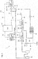
- the chilling machine 1 includes a refrigerant circuit 10 for circulating refrigerant, and a coolant circuit 100 for circulating the coolant(s) between a tank 101 and the supply destinations of the coolants A and B (the laser oscillator 2 and the laser processing machine 3).
- a chiller 70 that cools the coolant(s) by heat-exchanging between the refrigerant and the coolant(s) is provided.
- the coolant circuit 100 includes a first supply path 111 through which the low temperature coolant A (e.g. 24 ⁇ 1°C) is supplied to the laser oscillator 2 as a first supply destination, and a second supply path 112 through which the high temperature coolant B (e.g. 27°C or higher) is supplied to the laser processing machine 3 as a second supply destination.
- the low temperature coolant A e.g. 24 ⁇ 1°C
- the high temperature coolant B e.g. 27°C or higher
- the first supply path 111 is connected with the supply port A1 of the laser oscillator 2, and the second supply path 112 is connected with the supply port B1 of the laser processing machine 3 via a second reheater 22 and a first reheater 21 that will be described later.
- an upstream portion of the second supply path 112 is shared with the first supply path 111 (it can be also stated that the second supply path 112 is branched from the first supply path 111).
- the discharge port A2 of the laser oscillator 2 is connected with the tank 101 by a return path 113, and the discharge port B2 of the laser processing machine 3 is connected with the tank 101 by a return path 114.
- One end of the first supply path 111 is connected with a discharge port near a bottom of the tank 101, and the other end thereof is connected with an inlet port of the chiller 70.
- a pressure pump (not shown in the drawings) and a valve(s) (not shown in the drawings) are also provided.
- An outlet port of the chiller 70 is connected with the supply port A1 of the laser oscillator 2.
- One end of the second supply path 112 is connected with the discharge port near the bottom of the tank 101, and the other end thereof is connected with the supply port B1 of the laser processing machine 3.
- a pressure pump (not shown in the drawings) and a valve(s) (not shown in the drawings) are also provided (in the present embodiment, the pressure pump and the valve are provided on a supply section with the first supply path 111).
- the reheaters (the second reheater 22 and the first reheater 21) interposed on the circulation path of the refrigerant circuit 10 are provided.
- the coolant B that has passed through the reheaters 21 and 22 is supplied to the laser processing machine 3.
- a compressor 11, a condenser 12, an expansion valve (first expander) 13, an evaporator 14 disposed within the chiller 70, and an accumulator 15 are provided on the refrigerant circuit 10 in this order.
- the refrigerant discharged from the compressor 11 is condensed at the condenser 12.
- the refrigerant condensed at the condenser 12 is decompressed at the expansion valve 13, and then evaporated at the evaporator 14.
- the evaporated refrigerant is returned to the compressor 11 through the accumulator 15.
- This path is a main portion of a refrigeration cycle 10A.
- the compressor 11 has specification capable of controlling quantity of the refrigerant circulated in the refrigeration cycle 10A.
- first reheater 21 and the second reheater that can be selectively utilized are provided between the compressor 11 and the condenser 12 on the refrigerant circuit 10.
- the reheaters 21 and 22 are heat exchangers that increase the temperature of the coolant B to be supplied to the laser processing machine 3 through the second supply path 112 to 27°C or higher by utilizing heats of high temperature refrigerant discharged from the compressor 11 (i.e. exhausted heats of the laser oscillator 2 that have been absorbed from the coolant at the chiller 70).
- a first selective path 61, a second selective path 62, and a third selective path 63 are provided in the refrigerant circuit 10.
- the first selective path 61 supplies the refrigerant discharged from the compressor 11 to the condenser 12 by bypassing the first reheater 21.
- the second selective path 62 supplies the refrigerant discharged from the compressor 11 to the condenser 12 through the first reheater 21. Note that, in the present embodiment, an upstream portion and a downstream portion of the second selective path 62 are shared with the first selective path 61 (it can be also stated that the second selective path 62 is branched from the first selective path 61, and then converged into the first selective path 61).
- the third selective path 63 is branched from the second selective path 62 between the first reheater 21 and the condenser 12, and supplies the refrigerant that has passed through the first reheater 21 to the evaporator 14 through the second reheater 22 and a capillary tube (second expander) 23 by bypassing the condenser 12 and the expansion valve 13.
- the coolant is circulated to the second reheater 22 in series with the first reheater 21, and the second reheater 22 increases the temperature of the coolant by heats of the refrigerant that has passed through the first reheater 21.
- the capillary tube 23 decompresses the refrigerant that has passed through the second reheater 22, and sends the decompressed refrigerant to the evaporator 14.
- a first electromagnetic valve SV1 is provided on an upstream portion of the first selective path 61
- a second electromagnetic valve SV2 is provided on an upstream portion of the second selective path 62
- a third electromagnetic valve SV3 is provided on an upstream portion of the third selective path 63.
- Quantities of the refrigerant(s) flowing through the selective paths 61 to 63 are controlled by adjusting valve openings of the electromagnetic valves SV1 to SV3 (adjusting between a range of the valve opening 0 to 100%).
- the first electromagnetic valve SV1 and the second electromagnetic valve SV2 correspond to a main component(s) of the controller that adjusts the quantities of the refrigerant(s) flowing through the first selective path 61 and/or the second selective path 62.
- the third electromagnetic valve SV3 corresponds to a main component of a flow divider that branches, in a state where the refrigerant is flowing through the second selective path 62, a flow of the refrigerant that has passed through the first reheater 21 also to the third selective path 63 from the second selective path 62.
- the first electromagnetic valve SV1, the second electromagnetic valve SV2, and the third electromagnetic valve SV3 are controlled by the controller 4.
- the first reheater 21 and the second reheater 22 are disposed on the coolant circuit 100 so that the coolant flows the first reheater 21 sequentially after the coolant has passed the second reheater 22. Therefore, in the first reheater 21 and the second reheater 22, the flow of the refrigerant and the flow of the coolant are counter to each other.
- the reheaters 21 and 22 are a counter-flow type heat exchanger. By running the flow of the refrigerant and the flow of the coolant counter to each other, it becomes possible to improve efficiency of heat-exchanging between the refrigerant and the coolant at the reheaters 21 and 22.
- the first electromagnetic valve SV1 is closed, the second electromagnetic valve SV2 is opened and the third electromagnetic valve SV3 is closed.
- the refrigerant discharged from the compressor 11 flows through the second selective path 62 to exchange heats with the coolant at the first reheater 21.
- the exhausted heats of the laser oscillator 2 absorbed by the refrigerant are utilized as energies for increasing the temperature of the coolant passing through the second supply path 112.
- the coolant B whose temperature has been increased to 27°C or higher at the first reheater 21 is supplied to the laser processing machine 3.
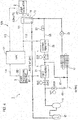
- the laser oscillator 2 When the laser oscillator 2 operates at its maximum output power (a high-load operation state) in the normal operation mode (i.e. in a state where the refrigerant is flowing through the second selective path 62 as indicated by a solid bold line(s) in Fig. 4 ), its exhausted heats increase. As the result, there may be a case where the temperature of the high temperature coolant B is increased excessively. In this case, a thermal load to the refrigeration cycle 10A may increase and thereby its cooling performance may become insufficient.
- the first electromagnetic valve SV1 is adjusted so that its valve opening is increased
- the second electromagnetic valve SV2 is adjusted so that its valve opening is decreased. Therefore, as shown by a dotted bold line(s) in Fig. 4 , quantity of the refrigerant passing through the first selective path 61 (quantity of the refrigerant not passing through the first reheater 21) increases. Namely, quantity of the refrigerant passing through the second selective path 62 (quantity of the refrigerant passing through the first reheater 21) decreases. As the result, cooling capacity by the refrigerant circuit 10 for the coolant flowing through the second supply path 112 is enhanced, and the temperature of the high temperature coolant B to be supplied to the laser processing machine 3 is restricted from increasing.
- the second electromagnetic valve SV2 is fully closed and the first electromagnetic valve SV1 is fully opened, so that the refrigerant bypasses the first reheater 21 and is supplied directly to the condenser 12. Since the refrigerant supplied to the condenser 12 increases to the maximum, the cooling capacity becomes maximum.
- the first electromagnetic valve SV1 is closed, the second electromagnetic valve SV2 is opened and the third electromagnetic valve SV3 is opened, as shown in Fig. 5 .
- the refrigerant sequentially flows through the first reheater 21 and the second reheater 22. Therefore, by utilizing the two reheaters 21 and 22, it becomes possible to enhance the temperature increase of the coolant by heats of the refrigerant discharged from the compressor 11 almost doubly. As the result, it becomes possible to prevent the temperature of the high temperature coolant B from decreasing (insufficient increase of the temperature), and to prevent dew condensation of piping paths of the laser processing machine 3 under hot and humid environment.
- the first electromagnetic valve SV1 is opened, the second electromagnetic valve SV2 is closed and the third electromagnetic valve SV3 is closed.
- the refrigerant discharged from the compressor 11 bypasses the first reheater 21, and is supplied directly to the condenser 12. Since the refrigerant supplied to the condenser 12 increases to the maximum, the cooling performance becomes maximum. At this time, the reheaters 21 and 22 don't increase the temperature of the coolant.
Landscapes
- Engineering & Computer Science (AREA)
- Physics & Mathematics (AREA)
- Mechanical Engineering (AREA)
- Thermal Sciences (AREA)
- General Engineering & Computer Science (AREA)
- Electromagnetism (AREA)
- Plasma & Fusion (AREA)
- Optics & Photonics (AREA)
- Lasers (AREA)
- Air Conditioning Control Device (AREA)
Applications Claiming Priority (2)
| Application Number | Priority Date | Filing Date | Title |
|---|---|---|---|
| JP2014045928A JP6317959B2 (ja) | 2014-03-10 | 2014-03-10 | 冷却装置 |
| PCT/JP2015/052502 WO2015137000A1 (fr) | 2014-03-10 | 2015-01-29 | Machine de réfrigération |
Publications (2)
| Publication Number | Publication Date |
|---|---|
| EP3128261A1 true EP3128261A1 (fr) | 2017-02-08 |
| EP3128261A4 EP3128261A4 (fr) | 2017-11-29 |
Family
ID=54071454
Family Applications (1)
| Application Number | Title | Priority Date | Filing Date |
|---|---|---|---|
| EP15760659.1A Pending EP3128261A4 (fr) | 2014-03-10 | 2015-01-29 | Machine de réfrigération |
Country Status (4)
| Country | Link |
|---|---|
| US (1) | US10197318B2 (fr) |
| EP (1) | EP3128261A4 (fr) |
| JP (1) | JP6317959B2 (fr) |
| WO (1) | WO2015137000A1 (fr) |
Families Citing this family (6)
| Publication number | Priority date | Publication date | Assignee | Title |
|---|---|---|---|---|
| JP6660873B2 (ja) * | 2016-12-22 | 2020-03-11 | 株式会社大気社 | ヒートポンプ式温調装置 |
| CN106532414A (zh) * | 2016-12-30 | 2017-03-22 | 安徽亿瑞深冷能源科技有限公司 | 一种大功率激光器用相变蓄冷式液冷源 |
| CN109616856A (zh) * | 2018-11-26 | 2019-04-12 | 中国工程物理研究院应用电子学研究所 | 一种激光器温控系统及其控制方法 |
| JP2020118348A (ja) * | 2019-01-23 | 2020-08-06 | 株式会社アマダ | チラー |
| US20200309394A1 (en) * | 2019-03-26 | 2020-10-01 | Johnson Controls Technology Company | Hvac unit utilizing selectively modulated flow rates with hot gas reheat circuit |
| US11231211B2 (en) * | 2019-04-02 | 2022-01-25 | Johnson Controls Technology Company | Return air recycling system for an HVAC system |
Family Cites Families (16)
| Publication number | Priority date | Publication date | Assignee | Title |
|---|---|---|---|---|
| US3188829A (en) * | 1964-03-12 | 1965-06-15 | Carrier Corp | Conditioning apparatus |
| US3529432A (en) * | 1968-10-16 | 1970-09-22 | Otto J Nussbaum | Refrigeration system for widely varying ambient conditions |
| US4321797A (en) * | 1978-10-06 | 1982-03-30 | Air & Refrigeration Corp. | Quick connector and shut-off valve assembly for heat recovery system |
| US4270363A (en) | 1979-04-16 | 1981-06-02 | Schneider Metal Manufacturing Company | Refrigerating machine including energy conserving heat exchange apparatus |
| US5265433A (en) * | 1992-07-10 | 1993-11-30 | Beckwith William R | Air conditioning waste heat/reheat method and apparatus |
| JPH06323643A (ja) * | 1993-05-17 | 1994-11-25 | Mitsubishi Heavy Ind Ltd | ヒートポンプ |
| JP2880424B2 (ja) * | 1995-03-20 | 1999-04-12 | オリオン機械株式会社 | レーザー加工機用クーラーのミラー回路温調装置 |
| US5826433A (en) * | 1997-03-25 | 1998-10-27 | Dube; Serge | Refrigeration system with heat reclaim and efficiency control modulating valve |
| US20060179874A1 (en) * | 2005-02-17 | 2006-08-17 | Eric Barger | Refrigerant based heat exchange system |
| JP5098472B2 (ja) * | 2007-07-06 | 2012-12-12 | 三浦工業株式会社 | 冷凍機を用いたチラー |
| JP4803199B2 (ja) * | 2008-03-27 | 2011-10-26 | 株式会社デンソー | 冷凍サイクル装置 |
| JP5470520B2 (ja) * | 2010-02-12 | 2014-04-16 | オリオン機械株式会社 | 多系統冷却装置及びその給水設定方法 |
| JP2012245501A (ja) * | 2011-05-31 | 2012-12-13 | Orion Machinery Co Ltd | 圧縮空気除湿装置 |
| US9008136B2 (en) * | 2012-03-22 | 2015-04-14 | Ams Research Corporation | Laser system chiller |
| WO2014136447A1 (fr) * | 2013-03-06 | 2014-09-12 | パナソニック株式会社 | Dispositif de climatisation de véhicule |
| JP6259419B2 (ja) * | 2015-06-01 | 2018-01-10 | ファナック株式会社 | 扉の開放の可否を判定する機能を備えたレーザ装置 |
-
2014
- 2014-03-10 JP JP2014045928A patent/JP6317959B2/ja not_active Expired - Fee Related
-
2015
- 2015-01-29 US US15/122,272 patent/US10197318B2/en active Active
- 2015-01-29 WO PCT/JP2015/052502 patent/WO2015137000A1/fr not_active Ceased
- 2015-01-29 EP EP15760659.1A patent/EP3128261A4/fr active Pending
Also Published As
| Publication number | Publication date |
|---|---|
| WO2015137000A1 (fr) | 2015-09-17 |
| EP3128261A4 (fr) | 2017-11-29 |
| US10197318B2 (en) | 2019-02-05 |
| JP6317959B2 (ja) | 2018-04-25 |
| JP2015169404A (ja) | 2015-09-28 |
| US20160370047A1 (en) | 2016-12-22 |
Similar Documents
| Publication | Publication Date | Title |
|---|---|---|
| US10197318B2 (en) | Chilling machine | |
| EP2428742B1 (fr) | Dispositif de climatisation | |
| JP5501179B2 (ja) | フリークーリング併用中温熱源システム | |
| US9175889B2 (en) | Heat source system and control method thereof | |
| US20130050931A1 (en) | System and method for cooling a processing system | |
| JP6444618B2 (ja) | 冷却システム、冷却式コンピュータシステムおよびコンピュータ設備 | |
| US10248142B2 (en) | Cooling apparatus, cooling method, and data processing system | |
| TWI659186B (zh) | 液體溫度調節裝置及溫度控制系統 | |
| AU2005268223B2 (en) | Refrigerating apparatus | |
| JP6486500B2 (ja) | 排熱回収システム | |
| US20130291575A1 (en) | Cooling system and method for operating same | |
| KR102791580B1 (ko) | 냉각 시스템 | |
| JP6257993B2 (ja) | 冷凍システムおよび冷凍システムの台数制御方法 | |
| KR20100063680A (ko) | 흡수 냉각기에서 온도를 제어하기 위한 방법 및 시스템 | |
| KR101120251B1 (ko) | 흡수 냉각기에서 방열하기 위한 방법 및 시스템 | |
| JP2009168403A (ja) | チラー装置 | |
| WO2018105702A1 (fr) | Système de source de chaleur, dispositif de commande, procédé de commande et programme | |
| JP2010181088A (ja) | ヒートポンプ装置 | |
| US20230400213A1 (en) | Low charge chiller and free cooling | |
| JP6814071B2 (ja) | 廃熱利用吸収式冷凍システム及び吸収式冷凍機 | |
| WO2016170616A1 (fr) | Climatiseur | |
| JP7840465B1 (ja) | 冷凍機システム | |
| JP5696319B2 (ja) | 圧縮空気除湿装置 | |
| JP2009097750A (ja) | 精密温度調整装置 | |
| CN121996042A (zh) | 相变储能与混相冷板冷却系统及服务器冷却控制方法 |
Legal Events
| Date | Code | Title | Description |
|---|---|---|---|
| STAA | Information on the status of an ep patent application or granted ep patent |
Free format text: STATUS: THE INTERNATIONAL PUBLICATION HAS BEEN MADE |
|
| PUAI | Public reference made under article 153(3) epc to a published international application that has entered the european phase |
Free format text: ORIGINAL CODE: 0009012 |
|
| STAA | Information on the status of an ep patent application or granted ep patent |
Free format text: STATUS: REQUEST FOR EXAMINATION WAS MADE |
|
| 17P | Request for examination filed |
Effective date: 20161007 |
|
| AK | Designated contracting states |
Kind code of ref document: A1 Designated state(s): AL AT BE BG CH CY CZ DE DK EE ES FI FR GB GR HR HU IE IS IT LI LT LU LV MC MK MT NL NO PL PT RO RS SE SI SK SM TR |
|
| AX | Request for extension of the european patent |
Extension state: BA ME |
|
| DAX | Request for extension of the european patent (deleted) | ||
| A4 | Supplementary search report drawn up and despatched |
Effective date: 20171103 |
|
| RIC1 | Information provided on ipc code assigned before grant |
Ipc: F25B 29/00 20060101ALI20171026BHEP Ipc: H01S 3/04 20060101ALI20171026BHEP Ipc: F25B 1/00 20060101AFI20171026BHEP Ipc: F25B 41/04 20060101ALI20171026BHEP Ipc: F25B 6/02 20060101ALI20171026BHEP Ipc: F25B 49/02 20060101ALI20171026BHEP Ipc: F25B 40/04 20060101ALI20171026BHEP Ipc: F25B 6/04 20060101ALI20171026BHEP |
|
| STAA | Information on the status of an ep patent application or granted ep patent |
Free format text: STATUS: EXAMINATION IS IN PROGRESS |
|
| 17Q | First examination report despatched |
Effective date: 20210208 |
|
| P01 | Opt-out of the competence of the unified patent court (upc) registered |
Effective date: 20230527 |