EP3128303A2 - In-situ-spektralprozessüberwachung - Google Patents
In-situ-spektralprozessüberwachung Download PDFInfo
- Publication number
- EP3128303A2 EP3128303A2 EP16182511.2A EP16182511A EP3128303A2 EP 3128303 A2 EP3128303 A2 EP 3128303A2 EP 16182511 A EP16182511 A EP 16182511A EP 3128303 A2 EP3128303 A2 EP 3128303A2
- Authority
- EP
- European Patent Office
- Prior art keywords
- probe
- light
- outer housing
- probe according
- optical filter
- Prior art date
- Legal status (The legal status is an assumption and is not a legal conclusion. Google has not performed a legal analysis and makes no representation as to the accuracy of the status listed.)
- Granted
Links
Images




Classifications
-
- G—PHYSICS
- G01—MEASURING; TESTING
- G01J—MEASUREMENT OF INTENSITY, VELOCITY, SPECTRAL CONTENT, POLARISATION, PHASE OR PULSE CHARACTERISTICS OF INFRARED, VISIBLE OR ULTRAVIOLET LIGHT; COLORIMETRY; RADIATION PYROMETRY
- G01J3/00—Spectrometry; Spectrophotometry; Monochromators; Measuring colours
- G01J3/02—Details
- G01J3/027—Control of working procedures of a spectrometer; Failure detection; Bandwidth calculation
-
- G—PHYSICS
- G01—MEASURING; TESTING
- G01N—INVESTIGATING OR ANALYSING MATERIALS BY DETERMINING THEIR CHEMICAL OR PHYSICAL PROPERTIES
- G01N21/00—Investigating or analysing materials by the use of optical means, i.e. using sub-millimetre waves, infrared, visible or ultraviolet light
- G01N21/17—Systems in which incident light is modified in accordance with the properties of the material investigated
- G01N21/25—Colour; Spectral properties, i.e. comparison of effect of material on the light at two or more different wavelengths or wavelength bands
-
- G—PHYSICS
- G01—MEASURING; TESTING
- G01N—INVESTIGATING OR ANALYSING MATERIALS BY DETERMINING THEIR CHEMICAL OR PHYSICAL PROPERTIES
- G01N21/00—Investigating or analysing materials by the use of optical means, i.e. using sub-millimetre waves, infrared, visible or ultraviolet light
- G01N21/84—Systems specially adapted for particular applications
- G01N21/85—Investigating moving fluids or granular solids
-
- G—PHYSICS
- G01—MEASURING; TESTING
- G01J—MEASUREMENT OF INTENSITY, VELOCITY, SPECTRAL CONTENT, POLARISATION, PHASE OR PULSE CHARACTERISTICS OF INFRARED, VISIBLE OR ULTRAVIOLET LIGHT; COLORIMETRY; RADIATION PYROMETRY
- G01J3/00—Spectrometry; Spectrophotometry; Monochromators; Measuring colours
- G01J3/02—Details
- G01J3/0289—Field-of-view determination; Aiming or pointing of a spectrometer; Adjusting alignment; Encoding angular position; Size of measurement area; Position tracking
-
- G—PHYSICS
- G01—MEASURING; TESTING
- G01J—MEASUREMENT OF INTENSITY, VELOCITY, SPECTRAL CONTENT, POLARISATION, PHASE OR PULSE CHARACTERISTICS OF INFRARED, VISIBLE OR ULTRAVIOLET LIGHT; COLORIMETRY; RADIATION PYROMETRY
- G01J3/00—Spectrometry; Spectrophotometry; Monochromators; Measuring colours
- G01J3/02—Details
- G01J3/0291—Housings; Spectrometer accessories; Spatial arrangement of elements, e.g. folded path arrangements
-
- G—PHYSICS
- G01—MEASURING; TESTING
- G01J—MEASUREMENT OF INTENSITY, VELOCITY, SPECTRAL CONTENT, POLARISATION, PHASE OR PULSE CHARACTERISTICS OF INFRARED, VISIBLE OR ULTRAVIOLET LIGHT; COLORIMETRY; RADIATION PYROMETRY
- G01J3/00—Spectrometry; Spectrophotometry; Monochromators; Measuring colours
- G01J3/02—Details
- G01J3/0297—Constructional arrangements for removing other types of optical noise or for performing calibration
-
- G—PHYSICS
- G01—MEASURING; TESTING
- G01J—MEASUREMENT OF INTENSITY, VELOCITY, SPECTRAL CONTENT, POLARISATION, PHASE OR PULSE CHARACTERISTICS OF INFRARED, VISIBLE OR ULTRAVIOLET LIGHT; COLORIMETRY; RADIATION PYROMETRY
- G01J3/00—Spectrometry; Spectrophotometry; Monochromators; Measuring colours
- G01J3/12—Generating the spectrum; Monochromators
-
- G—PHYSICS
- G01—MEASURING; TESTING
- G01N—INVESTIGATING OR ANALYSING MATERIALS BY DETERMINING THEIR CHEMICAL OR PHYSICAL PROPERTIES
- G01N21/00—Investigating or analysing materials by the use of optical means, i.e. using sub-millimetre waves, infrared, visible or ultraviolet light
- G01N21/01—Arrangements or apparatus for facilitating the optical investigation
-
- G—PHYSICS
- G01—MEASURING; TESTING
- G01N—INVESTIGATING OR ANALYSING MATERIALS BY DETERMINING THEIR CHEMICAL OR PHYSICAL PROPERTIES
- G01N21/00—Investigating or analysing materials by the use of optical means, i.e. using sub-millimetre waves, infrared, visible or ultraviolet light
- G01N21/17—Systems in which incident light is modified in accordance with the properties of the material investigated
- G01N21/25—Colour; Spectral properties, i.e. comparison of effect of material on the light at two or more different wavelengths or wavelength bands
- G01N21/27—Colour; Spectral properties, i.e. comparison of effect of material on the light at two or more different wavelengths or wavelength bands using photo-electric detection ; circuits for computing concentration
-
- G—PHYSICS
- G01—MEASURING; TESTING
- G01N—INVESTIGATING OR ANALYSING MATERIALS BY DETERMINING THEIR CHEMICAL OR PHYSICAL PROPERTIES
- G01N21/00—Investigating or analysing materials by the use of optical means, i.e. using sub-millimetre waves, infrared, visible or ultraviolet light
- G01N21/84—Systems specially adapted for particular applications
- G01N21/85—Investigating moving fluids or granular solids
- G01N21/8507—Probe photometers, i.e. with optical measuring part dipped into fluid sample
-
- G—PHYSICS
- G01—MEASURING; TESTING
- G01J—MEASUREMENT OF INTENSITY, VELOCITY, SPECTRAL CONTENT, POLARISATION, PHASE OR PULSE CHARACTERISTICS OF INFRARED, VISIBLE OR ULTRAVIOLET LIGHT; COLORIMETRY; RADIATION PYROMETRY
- G01J3/00—Spectrometry; Spectrophotometry; Monochromators; Measuring colours
- G01J3/12—Generating the spectrum; Monochromators
- G01J2003/1226—Interference filters
- G01J2003/123—Indexed discrete filters
-
- G—PHYSICS
- G01—MEASURING; TESTING
- G01J—MEASUREMENT OF INTENSITY, VELOCITY, SPECTRAL CONTENT, POLARISATION, PHASE OR PULSE CHARACTERISTICS OF INFRARED, VISIBLE OR ULTRAVIOLET LIGHT; COLORIMETRY; RADIATION PYROMETRY
- G01J3/00—Spectrometry; Spectrophotometry; Monochromators; Measuring colours
- G01J3/12—Generating the spectrum; Monochromators
- G01J2003/1226—Interference filters
- G01J2003/1234—Continuously variable IF [CVIF]; Wedge type
-
- G—PHYSICS
- G01—MEASURING; TESTING
- G01J—MEASUREMENT OF INTENSITY, VELOCITY, SPECTRAL CONTENT, POLARISATION, PHASE OR PULSE CHARACTERISTICS OF INFRARED, VISIBLE OR ULTRAVIOLET LIGHT; COLORIMETRY; RADIATION PYROMETRY
- G01J3/00—Spectrometry; Spectrophotometry; Monochromators; Measuring colours
- G01J3/12—Generating the spectrum; Monochromators
- G01J2003/1226—Interference filters
- G01J2003/1239—Interference filters and separate detectors
-
- G—PHYSICS
- G01—MEASURING; TESTING
- G01N—INVESTIGATING OR ANALYSING MATERIALS BY DETERMINING THEIR CHEMICAL OR PHYSICAL PROPERTIES
- G01N2201/00—Features of devices classified in G01N21/00
- G01N2201/06—Illumination; Optics
- G01N2201/061—Sources
-
- G—PHYSICS
- G01—MEASURING; TESTING
- G01N—INVESTIGATING OR ANALYSING MATERIALS BY DETERMINING THEIR CHEMICAL OR PHYSICAL PROPERTIES
- G01N2201/00—Features of devices classified in G01N21/00
- G01N2201/06—Illumination; Optics
- G01N2201/062—LED's
-
- G—PHYSICS
- G01—MEASURING; TESTING
- G01N—INVESTIGATING OR ANALYSING MATERIALS BY DETERMINING THEIR CHEMICAL OR PHYSICAL PROPERTIES
- G01N2201/00—Features of devices classified in G01N21/00
- G01N2201/06—Illumination; Optics
- G01N2201/068—Optics, miscellaneous
Definitions
- Manufacturing processes used in the preparation of pharmaceuticals, food, distillates and chemical compounds may include some type of sensor inspection of the mixing process, for example, spectral, pH, and thermal interrogation. These sensors are typically attached to a wall of a processing vessel, and monitor parameters of the process using a probe protruding into the manufacturing process. However, the stationary nature of sensors having a fixed position limits inspection capabilities to the product in the immediate vicinity of the sensor's fixed position and may not provide information about other parts of the process.
- a collimating element may be required prior to variable optical filters to prevent the spectral selectivity of the linearly variable filter from being degraded. Degradation may happen because the optical filter may include a stack of thin dielectric films, and the wavelength selective properties of thin film filters are generally dependent on the angle of incidence of incoming light, which may deteriorate spectral selectivity and wavelength accuracy of thin film filters. However, for the device in the present disclosure it may be beneficial to reduce the size of the spectrometer even more by eliminating bulky lenses.
- a probe comprising:
- the optical filter comprises a spatially variable optical filter comprising
- the outer housing comprises a shape selected from the group consisting of spherical, cylindrical, prolate spheroid, ellipsoid, and toroidal.
- the outer housing comprises structural features arranged on the outside of the outer housing.
- the structural features include one or more of dimples, stubs, semi-circular or rectangular ribs, veins, or fingers.
- the probe further comprises a controller for storing the power readings for each constituent wavelength signal; and a communication device for transmitting the power readings to a remote base station.
- the communication device is a wireless communication device.
- the probe further comprises a positioning system tracker for determining an exact position or orientation of the probe.
- the probe further comprises a propulsion system for propelling the probe when immersed in the material.
- the probe further comprises a buoyancy adjusting system for adjusting the buoyancy of the probe when immersed in the material.
- the probe further comprises a storage compartment, and a hatch on the outer housing, the hatch operable to open and close the storage compartment.
- the probe further comprises a controller for storing the power readings for each constituent wavelength signal; wherein the controller comprises programming for signaling the hatch to open and release a substance from the storage component when the power readings reach a predetermined level.
- the communication device i s a wired communication device; and wherein the outer housing is tethered to a structure.
- the probe further comprises a window cleaner for removing debris from the window.
- the light source is mounted inside the outer housing for transmitting light through the window onto the material.
- the outer housing comprises a conduit extending therethrough from an opening in the outer housing to an outlet in the outer housing in between the light source and the optical filter.
- the probe further comprises:
- the probe further comprises a controller for storing the power readings for each constituent wavelength signal; wherein the controller includes programming for averaging the power readings from the constituent wavelength signals.
- the probe further comprises a controller for storing the power readings for each constituent wavelength signal; wherein the optical filters include different spectral passbands; and wherein the controller includes programming for combining the power readings from at least two detector arrays with different spectral passbands for generating a combined spectrum.
- the probe further comprises a shutter moveable within the outer housing into position between each light source and the corresponding optical filter for recalibrating each photodetector array after a predetermined time period.
- a monitoring system for monitoring a flowing material comprising:
- said base station receives power readings from said plurality of probes, and adjusts parameters for the flowing material i n response to the received power readings.
- a method of monitoring a flowing material comprising:
- the method further comprises adjusting parameters of said flowing materials in response to said power readings.
- the method further comprises adjusting the position of one of the probes by activating a propulsion system.
- the method further comprises releasing a substance from within at least one of said probes.
- the method further comprises capturing a sample of the material.
- FIG. 1 is a diagram of a top view
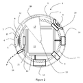
- FIG. 2 is a diagram of a cross-sectional view of a probe 1 according to an example implementation described below.
- the probe 1 may be a spatially variable filter (SVF) based spectral probe and includes an outer housing 2, which may be monolithic or multi sectional in form and may be hermetically sealed, thereby making the probe 1 robust for applications in which it is immersed in a material the probe is to measure.
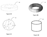
- the outer housing 2 may take one of several shapes or combinations thereof including, but not limited to, spherical 1 ( FIGS. 1 and 2 ), toroidal 1A ( FIG.
- the outer housing 2 may be made of or include a corrosion resistant material, such as stainless steel or a polymer material.
- the outer housing 2 may include one or more windows 4 spaced apart on the outer housing 2 or the outer housing 2 may be entirely transparent, i.e. a continuous window.
- the outer housing 2 may include any of 1 to 20 or more windows 4.
- the one or more windows 4 enable light reflected or refracted from the surrounding material to be captured by a corresponding linearly or spatially variable optical filter (SVF) 7 inside the probe 1.
- the reflected or refracted light may originate from one or more internal light sources 6, an external light source (not shown), ambient light, or a combination thereof.
- the SVF 7 may be discrete or continuously varying.
- the filter 7 may be based on other dispersive elements, e.g. gratings, or prisms, or may be based on other technology, such as MEMS, dyes and pigments, FTIR, and Raman.
- the SVF 7 separates the captured light into a spectrum of constituent wavelength signals for analysis.
- the windows 4 may be made of any suitable material, which is optically transparent for the desired transmission and reflected or refracted wavelengths, e.g., sapphire, silicon, Teflon, glass, etc.
- the internal light source 6 may be any suitable light source, e.g., a tungsten or LED light source, for transmitting the required wavelength band of light, e.g., visible (350 nm to 900 nm) and/or near infrared (NIR).
- the light source 6 may be comprised of one or more onboard incandescent lamps, e.g.
- vacuum tungsten lamps that provide broadband illumination, e.g., over 500 nm, over 700 nm, or over 1000 nm across the active range of the instrument, e.g., for the NIR in the 900 nm to 1700 nm range or in the 900 nm to 2150 nm range.
- One lamp 6 is sufficient; however, two lamps provides more light for the sample to interact with, hence shorter integration times.
- a conduit 19 extending from an opening in the outer housing 2 into the outer housing 2 to an outlet in the outer housing 2 may be provided enabling the passing of the flowing material, e.g. liquid, in between the light source 6 and the SVF 7 within the outer housing 2 for generating a transmission spectrum via the photodetectors 8 and the controller 12.
- the entire conduit 19 may be transparent to the transmitted light providing the necessary window for light to be transmitted from the light source 6 to the SVF 7, or one or more sections of the conduit 19 may be transparent providing the required window(s) for transmitted. refracted or reflected light.
- each SVF 7 Mounted beneath each SVF 7 is an array of photodetectors 8 forming a spectrometer 15 and generating a power reading for each constituent wavelength signal, thereby providing a spectrum of the reflected light.
- Each of the spectrometers 15 in each probe 1 may have a same spectral range or different spectrometers 15 may have different spectral ranges, e.g., overlapping or adjacent, to enable a broad spectral range to be stitched together from the individual spectrometers 15.
- Another example implementation may include a plurality of fiber bundles, each connecting to a single spectrometer 15 for light supply and data collection.
- Each bundle may communicate with a different window 4, and may be sequentially coupled to the single spectrometer 15.
- the photodetectors 8 may be a broadband detector array, e.g. more than 500 nm, more than 600 nm, or more than 700 nm wide, such as an indium gallium arsenide (InGaAs) detector covering 950 nm to 1650 nm, which may be extended to 1150 nm to 2150 nm, if desired or required.
- InGaAs indium gallium arsenide
- different spectrometers 15 within each probe 1 and different probes 1 within each system may have light sources 6, filters 7 and photodetectors 8 with different spectral ranges to cover a wider spectrum, e.g. ultraviolet to infrared, to enable a broad range of tests.
- An inner frame 11 may be mounted inside the outer housing 2 for supporting all of the SVF's 7 and photodetector arrays 8.
- the inner frame 11 may be made of or include one or more of a printed circuit board material, plastic, metal, ceramic, or other suitable material.
- a controller 12 may be mounted within or on the inner frame 11.
- the controller 12 may comprise suitable hardware, e.g., processor and memory chips mounted on printed circuit boards 13, along with suitable software for controlling all of the probes features, including spectrum generation, storing, and analysis, thereby providing a self-contained spectral probe 1 for immersion in the material, in particular when the material is moving or flowing in production.
- sensors 14 that may be included within the probe 1 include, but are not limited to, pH sensors, temperature sensors, pressure sensors, voltage sensors, velocity sensors, accelerometers, gyroscopes, and onboard cameras and forward looking infrared (FLIR) sensors.
- the probe 1 may include multiple similar and/or different sensors positioned around the outer housing 2 of the probe 1. These multiple sensors 14 can enable multiple data sets to be interrogated and improve the quality of the various measurements.
- Each of the sensors 14 along with the photodetector arrays 8 are connected to the controller 12 for control and data storage.
- Each probe 1 may include one or more shutters 16 within the outer housing 2, presenting calibration standards that moves into and out of location in front of each spectrometer 15 as part of a calibration process.
- the shutter 16 is mounted on the end of a rotating arm 17, which rotates about a central anchor 18 connected to the inner frame 11.
- the shutter 16 may recalibrate each spectrometer 15 after a predetermined time, e.g., at least every 5 minutes of operation, or after a predetermined number of uses, e.g., at least after every 300 spectral readings.
- the shutter 16 includes a calibrated reflectance standard to be rotated between the light source 6 and the window 4 to reflect the light from each light source 6 directly to the corresponding SVF 7. The reflectance from this known standard is then compared to previous tests to determine any change in illumination inside the probe 1.
- a communication module 21 is provided to enable control and/or data signals to be sent between the controller 12 and a base station (shown in FIGS. 7 to 9 ).
- the base station may be monitored by process monitoring engineers.
- the base station may include an automated process control system.
- the communication module 21 may be one or more of a wireless transceiver, a tethered communication cable connection, a photo transceiver, or an acoustical transceiver.
- a communication module 21 that is wireless may require antennas (not shown) positioned within or outside the outer housing 2 to achieve a real-time data transfer connection with the base station.
- the probe 1 may be self-powered with the use of replaceable of rechargeable batteries 22 and/or may be powered by a tethered power cable 24 adjacent to or coordinated with the optional communication cable connection (not shown).
- the power cable 24 may act as a communication line interconnecting the communication module 21 with the base station, and a tether for retrieving the probe 1 from the flowing media. Since the outer housing 2 may be hermetic, in an example implementation, the batteries 22 may be recharged using an induction connection.
- the controller circuit 12 may employ the use of a position system tracker (not shown), e.g., a global positioning system (GPS), to track the location of the probe 1 within the manufacturing or monitoring process.
- GPS global positioning system
- Another possible position tracking system comprises a radio transmitter (not shown) in the probe 1 for signaling an array of fixed directional radio receivers (not shown) positioned around a processing vessel.
- the array of fixed direction radio receivers may be used to coordinate the position of the probe 1 within the fixed processing vessel or system, whereby the base station and/or each probe's controller 12 may determine the probe's position.
- An inertial measurement unit (IMU) (not shown) may also be provided to enable the controller 12 or the base station to monitor the probe 1 for orientation and direction of travel within the process vessel.
- the probe 1 may be compatible with the process it is intended to interrogate, for example, the outer housing 2 may be made of IP67 or higher plastic NEMA 4, or the like, for package hermiticity and dust ingress and compatible chemical resistance from the material it is immersed in.
- the probe 1 may have variable buoyancy to adjust its buoyancy for use in a liquid process. As stated earlier, the probe 1 may be free to move within the process or may be attached to a fixed object via tether for post process retrieval.
- the outer housing 2 may be ruggedized to handle impacts from mixing or pressurized actions within the manufacture process.
- the probe 1 may be used in a process that requires extended monitoring times and the controller 12 may include programming to instruct the photodetector arrays 8 and sensors 14 to change into low power "Stand by" modes to conserve power during long process cycles.
- FIG. 4 is a diagram of an isometric view of a probe 1 according to an example implantation described below.
- the outer housing 2 of the probe 1 may include structural features that facilitate movement and stability with and through the material in which the probe is immersed.
- the structural features may include, for example, dimples, small or large ribs, stubs, semi-circular or rectangular ribs, veins, or fingers.
- the example implementation probe 1 in FIG. 4 includes a number of ribs 3.
- the structural features may provide protection for the probe 1 from contact with other objects, e.g., vessel walls.
- the structural features may also provide enhanced mixing and/or reduced clumping within the flowing material as the probe 1 travels through the flowing material.
- the structural features may also help in maintaining orientation of the probe 1 relative to the direction of the flow of the material in which the probe 1 is immersed, facilitate heat exchange with the material, and direct the material to be measured in front of the sensor windows 4 for measurement and for removing debris that may have become adhered thereto.
- the outer housing 2 may also include a hatch 9 for accessing a storage compartment 10.
- the hatch 9 may be opened by the controller 12 in response to a signal from the base station or in response to an internal signal from the controller 12, e.g., a spectrum reading or other test signal reaching a predetermined or desired level.
- the storage compartment 10 may contain a substance used to facilitate a chemical process, e.g., a catalyst.
- the storage compartment 10 may contain a substance used to mark a specific location, e.g., a dye.
- the storage compartment 10 may contain a substance used to alter the chemical parameters of the substance in which the probe 1 is immersed, e.g., pH or toxicity.
- the hatch 9 may be opened in response to a signal from the controller 12 and/or the base station to capture fluid from the material in which the probe is immersed in the storage compartment 10 for further testing or for controlling buoyancy of the probe 1 .
- the probe 1 may also include a separate buoyancy system 31, which will enable the buoyancy of each probe 1 to be individually adjusted before insertion into the flowing material or during active monitoring in the flowing material to enable the probe 1 to be guided or propelled to a different location, and different depths within the flowing material.
- the buoyancy system 31 may comprise a fluid expelling device for expelling fluid from a storage tank or bladder 32, thereby decreasing the density of the probe 1 and/or a fluid intake device for capturing surrounding fluid, thereby increasing the density of the probe 1.
- the probe 1 may also include a propulsion system 33, which will enable the position of each probe 1 to be adjusted by the controller 12 and/or the base station.
- the propulsion system 33 may include the release of a pressurized burst of fluid stored in a storage tank, an electro magnet, which may be energized to attract the probe 1 towards a metallic structure in the processing tank, or a propeller.
- a window cleaner system 25 which may be controlled by the controller 12, may be provided to periodically wipe or remove accumulated material off of the exterior of the windows 4.
- the cleaner system 25 may comprise an external concentric shell (not shown) with a wiper system mounted on the outer housing 1.
- the wiper system may include a wiper 26 mounted on a rotating or translating arm 27 which may be swept across the windows 4.
- the propulsion system 33 may spin the probe 1 at high speed within the volume of flowing material to throw off any accumulated material on the windows 4 by centrifugal force.
- Other cleaning systems may include one or more of a sonic agitator to provide sonic agitation to clear the windows 4, a heater to heat the windows 4 and to drive off moist powders, and a source of electricity to generate an electric discharge.
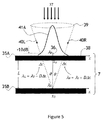
- FIG. 5 is a diagram of a side view of a dual SVF filter according to an example implementation described below.
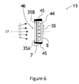
- FIG. 6 is a diagram of a side view of a spectrometer according to an example implementation described below.
- the spatially variable filter (SVF) 7 comprises a center wavelength of a passband varying, e.g. linearly or non-linearly, along an x-axis, and in some embodiments in the y-axis forming a 2D spatially variable filter (SVF).
- the SVF 7 may include sequentially disposed upstream 35A and downstream 35B spatially variable bandpass optical filters (SVF) separated by a predetermined fixed distance L in an optical path 36 of an optical beam 37, as disclosed in United States Patent Applications Nos. 14/608,356 and 14/818,986 , entitled "OPTICAL FILTER AND SPECTROMETER” by Smith et al, filed August 5, 2015.
- the upstream SVF 35A and the downstream SVF 35B each have a bandpass center wavelength varying in a mutually coordinated fashion along a common first direction 38 represented by the x-axes.
- the first direction 38 is transversal to the optical path 36.
- the bandpass center wavelength AT of both the upstream 35A and downstream 35B SVF have respective monotonic, linear dependences.
- the configuration of the optical filter 7 enables a dependence of spectral selectivity of the optical filter 7 on a degree of collimation of the optical beam 37 to be lessened as compared to a corresponding dependence of spectral selectivity of the downstream SVF 35B on the degree of collimation of the optical beam 37.
- the upstream 35A and downstream 35B SVF are aligned with each other, so that the reference point x 0 corresponding to the reference bandpass center wavelength ⁇ 0 of the downstream filter 35B is disposed directly under the reference point x 0 corresponding to the reference bandpass center wavelength ⁇ 0 of the upstream filter 35A.
- the upstream filter 35A functions as a spatial filter for the downstream filter 35B, defining a predetermined or preset angle of acceptance 39 for the downstream filter 35B.
- the angle of acceptance 39 is limited by left 40L and right 40R marginal rays at the reference wavelength ⁇ 0 each propagating at the angle ⁇ to a normal 36 to the upstream 35A and downstream 35B filters and striking downstream filter 359 at the same reference point x 0 .
- the angle of acceptance 30 may be derived from a passband 41A of the upstream filter 35A as follows.
- the left marginal ray 40L strikes the upstream filter 35A at a location x 0 - ⁇ x .
- the right marginal ray 40R strikes the upstream SVF 35A at a location x 0 + ⁇ x.
- the right marginal ray 40R will also be attenuated by the predetermined attenuation, e.g. 10dB. All rays at the reference wavelength ⁇ 0 within the acceptance angle 39 will be attenuated by a value smaller than the predetermined level, e.g. 10 dB ; and all rays at the reference wavelength ⁇ 0 outside the acceptance angle 39 will be attenuated by a value larger than the predetermined level, e.g.
- the upstream SVF 35A functions as spatial filter, effectively limiting the numerical aperture (NA) of incoming light to be separated in individual wavelengths by the downstream SVF 35B. This results in reduction of the dependence of spectral selectivity of the SVF 7 in comparison with the corresponding dependence of the spectral selectivity of the single downstream SVF 35B on the degree of collimation of the optical beam 37.
- spectral selectivity may include such parameters as passband width, stray light rejection, extinction ratio, etc.
- the center wavelengths ⁇ T of the upstream 35A and downstream 35B SVF may be monotonically increasing or decreasing in the first direction 38.
- the dependence of the bandpass center wavelength ⁇ T on the x -coordinate along the first direction 38 of the upstream SVF 35A and downstream 35B SVF may be identical, or different to enable adjustment of the acceptance angle and/or wavelength response of the optical filter 7.
- the bandpass center wavelengths ⁇ T of the upstream SVF 35A and downstream SVF 35B are aligned with each other, such that a line connecting positions corresponding to a same bandpass center wavelength ⁇ T of the upstream SVF 35A and the downstream SVF 35B forms an angle of less than a predetermined amount, e.g., 30°, with the normal 36 to the downstream SVF 35B.
- a predetermined amount e.g. 30°
- a lateral distance ⁇ x 1 along the first direction 38, corresponding to a bandwidth of the upstream SVF 35A, may be larger than a corresponding lateral distance ⁇ x 2 along the first direction 38, corresponding to a bandwidth of the downstream SVF 35B.
- the upstream SVF 35A and the downstream 35B SVF each have a 3dB passband no greater than 10% of a corresponding wavelength range of the upstream SVF 35A and the downstream SVF 35B.
- the spectrometer 15 includes the optical filter 7 and a photodetector array 8 disposed in the optical path downstream of the downstream SVF 35B.
- the photodetector array 8 may include pixels 44 disposed along the first direction 38 and optionally along a second perpendicular direction (into the page) for detecting optical power levels of individual spectral components of the optical beam, e.g., reflected by the flowing material from the light source 6.
- the photodetector array may be the 2D photodetector array disclosed in United States Patent Application No. 14/818,986 , entitled "OPTICAL FILTER AND SPECTROMETER" by Smith et al, filed August 5, 2015.
- the optical beam may be converging, diverging, collimated, etc.
- the dual-filter structure of the optical filter 7, including the upstream SVF 35A and the downstream SVF 35B results in lessening the dependence of spectral selectivity of the optical filter 7 on a degree of collimation of the returning light.
- the photodetector array 8 may be in direct contact with the downstream SVF 35B.
- the photodetector array 8 may be flooded with a potting material so as to form an encapsulation 45.
- One function of the encapsulation 45 is to insulate the photodetector array 8, while not obscuring a clear aperture 46 of the downstream SVF 35B of the optical filter 7.
- Another function of the encapsulation 45 is to protect edges of the upstream 35A and downstream 35B filters from impact, moisture, etc.
- FIGS. 7a and 7b are diagrams of side and end views, respectively, of a V-shaped mixing vessel for use with the probes 1.
- a processing tank 51 includes a support frame 52 for supporting a mixing vessel, such as V-shaped mixing vessel 53.
- the mixing vessel 53 includes at least one input port 54 for inputting the raw ingredients, and at least one output port 55 for discharging the finished product.
- An agitator or chopper 56 may be provided inside the mixing vessel 53 to reduce the size of the raw ingredients and/or mix the various raw ingredients together.
- the agitator 56 may be rotated using a sprocket and chain structure 57, or some other suitable driving assembly, which is driven by a motor 58.
- a control system 59 may be provided for controlling the input of the ingredients, the activation and speed of the agitator 56, as well as the timing of the discharge of the finished product via output port 55.
- the control system 59 may be controlled automatically according to pre-set programming stored on non-transitory memory actuated by a computer controller or may require human intervention at selected times.
- One or more probes 1 may be placed in with the raw ingredients, or even separately with different raw ingredients that are input through separate input ports 54, and follow along with the raw ingredients as they mix with each other and/or react with each other due to their chemical properties or other external factors, such as a change in temperature or pressure, or the addition of a catalyst.
- the probes 1, via the controller 12 and the communication module 21 may continually transmit spectrum data to the control system 59 (base station), e.g., wirelessly via WIFI, at predetermined time intervals to provide constant status updates of the chemical process.
- the control system 59 and/or the controller 12 may utilize the spectrum data and any other test data collected by the other sensors 14 in one of many different ways.
- control system 59 and/or the controller 12 may utilize the spectrum and test data to determine when the process is complete, i.e. to shut the process off, and output the finished product.
- control system 59 and/or the controller 12 may utilize the spectrum and test data to adjust the frequency or speed of the agitator 56 and/or to adjust the parameters of the chemical process, e.g. adjust any one or more of the temperature, the pressure, and the amount of catalyst.
- the control system 59 and/or the controller 12 may utilize the spectrum and test data to initiate subsequent steps in the process, e.g. as the spectrum and test data reach desired output levels.
- the control system 59 and/or the controller 12 may even distribute additional catalysts or ingredients at specific times based on the spectrum and test data from the storage compartment 10 via hatch 9.
- the control system 59 and/or the controller 12 may identify the position of the various probes 1 using each probe's positioning system, e.g" GPS, and may prioritize which probe 1 has greater significance in determining a next step based on the position of that probe 1.
- the control system 59 and/or the controller 12 may average the spectrum data for each probe 1.
- the averaging process may include eliminating high and low measurements or any measurement outside a predetermined deviation from the average of the remaining measurements.
- Averaging may include averaging the different spectra from the different windows 4/spectrometers 15 within each probe 1, and/or average the spectra from multiple probes 1 at multiple locations throughout the volume of flowing material.
- the controller 12 or the control system 59 may also include suitable programming to perform other spectrum processing including differencing similar or different spectra regions to compare readings or combining different overlapping or adjacent spectra to generate a wider spectrum.
- each probe 1 may be adjusted by utilizing the onboard propulsion system 33, the onboard buoyancy system 31, or by using a process propulsion system external to each probe 1, such as an electro-magnet 60 energized at a predetermined or desired location to attract one or more of the probes 1 in a required direction or into a desired zone of the vessel 53.
- a process propulsion system external to each probe 1, such as an electro-magnet 60 energized at a predetermined or desired location to attract one or more of the probes 1 in a required direction or into a desired zone of the vessel 53.
- the probes 1 can easily be collected for re-use when the finished product is output the outlet port 55.
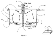
- the probes 1 may be used in a continuous process including a settling tank 61.
- the settling tank 61 includes an input port 62 for inputting raw or unprocessed ingredients proximate the middle of the tank 61, and an agitator or rake 63, which is mounted on the end of rotating shaft 64, and rotates around the bottom of the settling tank 61.
- An output port 65 is provided in the bottom of the settling tank 61 for outputting processed material, e.g. thickened liquid.
- An overflow channel 66 is provided around the top of the settling tank 61 to capture all the lighter fluid and materials, which rise to the top of the settling tank 61.
- One or more probes 1 may be placed in with the raw ingredients through input port 62, and follow along with the raw ingredients as they mix with each other and/or react with each other due to their chemical properties or other external factors, such as a change in temperature or pressure, or the addition of a catalyst.
- the controllers 12 may continually transmit spectrum data, e.g., wirelessly via WIFI, to a base station 69 at predetermined time intervals to provide constant status updates of the chemical process.
- the base station 69 and/or the controllers 12 may utilize the spectrum data and any other test data collected by the other sensors 14 in one of many different ways.
- the base station 69 and/or the controllers 12 may simply utilize the spectrum and test data to determine when the process has reached a certain stage, i.e., outputs the finished product via the output port 65.
- the base station 69 and/or the controllers 12 may utilize the spectrum and test data to adjust the frequency or speed of the rake 64 and/or to adjust the parameters of the chemical process, e.g. adjust any one or more of the temperature, the pressure, and the amount of catalyst.
- the base station 69 and/or the controllers 12 may utilize the spectrum and test data to initiate subsequent steps in the process, e.g., as the spectrum and test data reach desired output levels.
- the controllers 12 and/or the base station 69 may even distribute additional catalyst or ingredients at specific times based on the spectrum and test data from the storage compartment 10 via hatch 9.
- the base station 69 and/or the controllers 12 may identify the position of the various probes 1 using each probes positioning system, e.g., GPS, and may prioritize which probe 1 has greater significance in determining a next step based on the position.
- each probe 1 may have a plurality of spectrometers 15, the base station 69 and/or the controllers 12 may average the spectrum data for each probe 1.
- the averaging process may include eliminating high and low measurements or any measurement outside a predetermined deviation from the average of the remaining measurements.
- each probe 1 may be adjusted by the controllers 12 and/or the base station 69 utilizing the onboard propulsion system 33, the onboard buoyancy system 31 or by using a process propulsion system external to each probe 1, such as an electro-magnet 68 energized at a predetermined or desired location to attract one or more of the probes 1 in a required direction or into a desired zone of the settling tank 61.
- the probes 1 may have different buoyancy properties, e.g. one for settling to the bottom for output the output port 65 and one for rising to the top for output the overflow channel 66. Accordingly, the probes 1 can easily be collected for re-use when the finished product is output the various ports 65 and 66.
- a multi-step process such as a brewing process, may include several steps, e.g. lautering, boiling, fermenting, conditioning, filtering, and packaging, which may require precision monitoring provided by a monitoring system including a base station 70 and a plurality of probes 1 communicating via a wireless network, e.g., WIFI.
- the probes 1 may be inserted into each processing tank at each step or the probes 1 may travel with the ingredients through various steps and processing vessels.
- Malting is the process where barley grain 71 is made ready for brewing. When malting is complete, the grains 71 are milled or crushed in a mill 72 to break apart the kernels and expose the cotyledon, which contains the majority of the carbohydrates and sugars.
- Mashing converts the starches released during the malting stage into sugars that can be fermented.
- the milled grain is mixed with hot water in a large vessel known as a mash tun 73.
- a mash tun 73 In this vessel, the grain and water are mixed together to create a cereal mash.
- Naturally occurring enzymes present in the malt convert the starches (long chain carbohydrates) in the grain into smaller molecules or simple sugars (mono-, di-, and trisaccharides). This "conversion” is called saccharification.
- the result of the mashing process is a sugar rich liquid or "wort", which is then strained through the bottom of the mash tun 73 or in a separate tank 74 in a process known as lautering.
- the probes 1 may be deposited into the mash tun 73 to monitor the concentration of enzymes and the concentration of starches in the wort. Prior to lautering, the mash temperature may be raised to about 75-78 °C (167-172 °F) (known as a mashout) to deactivate enzymes. Probes 1 may be used near the bottom of the mash tun 73 or lautering tank 74 to ensure the temperature is within the desired range throughout the container using a temperature sensor 14, and to ensure the concentration of enzymes is reduced to a desired or acceptable level using one of the probe spectrometers. Additional water may be sprinkled on the grains to extract additional sugars in a process known as sparging.
- the wort is moved into a large tank 75 known as a "copper” or kettle where it is boiled with hops and sometimes other ingredients 76, such as herbs or sugars. This stage is where many chemical and technical reactions take place, and where important decisions about the flavor, color, and aroma of the beer are made.
- the boiling process serves to terminate enzymatic processes, precipitate proteins, isomerize hop resins, and concentrate and sterilize the wort. Hops add flavor, aroma and bitterness to the beer.
- the spectrum signals from the probes 1 may be used to determine the concentrations of the various elements and the color of the wort
- the hopped wort settles to clarify in a vessel called a "whirlpool" 77, where the more solid particles in the wort are separated out.
- the wort is rapidly cooled via a heat exchanger 78 to a temperature where yeast can be added.
- the heat exchanger 78 is comprised of tubing inside a tub of cold water. It is very important to quickly cool the wort to a level where yeast can be added safely as yeast is unable to grow in high temperatures. Accordingly, temperature sensors 14 on the probes 1 may quickly determine when the wort has cooled to the required temperature evenly throughout the heat exchanger 78.
- the cooled wort goes into a fermentation tank 79. A type of yeast is selected and added, or "pitched", to the fermentation tank 79.
- the fermenting process begins, where the sugars turn into alcohol, carbon dioxide and other components.
- the probes 1 provide spectral signals relating to the concentration of those elements.
- the brewer may rack the beer into a new tank, called a conditioning tank 80. Conditioning of the beer is the process in which the beer ages, the flavor becomes smoother, and flavors that are unwanted dissipate.
- the spectrum signals from the probes 1 provide a clear indication of when the beer has reached its optimum condition, as well as the monitoring of other characteristics, such as pH.
- the beer may be filtered using a filter 81 and force carbonated for bottling, or fined in the cask.
- the probes 1 may also be used in a much larger monitoring system, such as in active rivers, lakes, oceans and other waterways to monitor the concentration of various elements, such as pollutants, e.g. oil spills, along with other contributing factors, for example temperature and pH.
- pollutants e.g. oil spills
- the combination of the location and time of detection, and the type(s) of the pollutant detected, may enable determination of the source of pollution, as well as the resultant damage, e.g. changes in water characteristics, downstream.
- the probes 1 may also be used for monitoring humans or other animals in-vivo.
- a probe 1 may be ingested and the spectral data may be transmitted to a doctor's base station as the probe 1 traverses the patient's digestive system to monitor content, pH, temperature and various other characteristics.
- the probes 1 may be dropped from some form of flying machine, e.g., airplane, balloon, helicopter or spacecraft, to monitor various atmospheric characteristics, e.g., ozone, allergens, pollutants.
- flying machine e.g., airplane, balloon, helicopter or spacecraft
- atmospheric characteristics e.g., ozone, allergens, pollutants.
Landscapes
- Physics & Mathematics (AREA)
- Spectroscopy & Molecular Physics (AREA)
- General Physics & Mathematics (AREA)
- Health & Medical Sciences (AREA)
- Life Sciences & Earth Sciences (AREA)
- Chemical & Material Sciences (AREA)
- Analytical Chemistry (AREA)
- Biochemistry (AREA)
- General Health & Medical Sciences (AREA)
- Immunology (AREA)
- Pathology (AREA)
- Engineering & Computer Science (AREA)
- Mathematical Physics (AREA)
- Theoretical Computer Science (AREA)
- Investigating Or Analysing Materials By Optical Means (AREA)
- Spectrometry And Color Measurement (AREA)
- Investigating Materials By The Use Of Optical Means Adapted For Particular Applications (AREA)
Applications Claiming Priority (1)
| Application Number | Priority Date | Filing Date | Title |
|---|---|---|---|
| US14/819,179 US9945790B2 (en) | 2015-08-05 | 2015-08-05 | In-situ spectral process monitoring |
Publications (3)
| Publication Number | Publication Date |
|---|---|
| EP3128303A2 true EP3128303A2 (de) | 2017-02-08 |
| EP3128303A3 EP3128303A3 (de) | 2017-05-03 |
| EP3128303B1 EP3128303B1 (de) | 2023-10-04 |
Family
ID=56876901
Family Applications (1)
| Application Number | Title | Priority Date | Filing Date |
|---|---|---|---|
| EP16182511.2A Active EP3128303B1 (de) | 2015-08-05 | 2016-08-03 | In-situ-spektralprozessüberwachung |
Country Status (6)
| Country | Link |
|---|---|
| US (2) | US9945790B2 (de) |
| EP (1) | EP3128303B1 (de) |
| JP (2) | JP6388623B2 (de) |
| KR (2) | KR101885183B1 (de) |
| CN (2) | CN110702619B (de) |
| CA (1) | CA2938011C (de) |
Cited By (3)
| Publication number | Priority date | Publication date | Assignee | Title |
|---|---|---|---|---|
| WO2020041813A1 (de) * | 2018-08-29 | 2020-03-05 | Erema Engineering Recycling Maschinen Und Anlagen Gesellschaft M.B.H. | Verfahren und vorrichtung zum aufbereiten, bearbeiten und/oder recyceln von materialien |
| JP7129849B2 (ja) | 2015-08-05 | 2022-09-02 | ヴァイアヴィ・ソリューションズ・インコーポレイテッド | in-situスペクトル工程監視 |
| RU2805333C2 (ru) * | 2018-08-29 | 2023-10-16 | Эрема Энджиниринг Рисайклинг Машинен Унд Анлаген Гезелльшафт М.Б.Х. | Способ и устройство для подготовки, обработки и/или рециклинга материалов |
Families Citing this family (3)
| Publication number | Priority date | Publication date | Assignee | Title |
|---|---|---|---|---|
| KR102197456B1 (ko) | 2014-01-31 | 2020-12-31 | 비아비 솔루션즈 아이엔씨. | 광학 필터 및 분광계 |
| US10048127B2 (en) | 2015-08-05 | 2018-08-14 | Viavi Solutions Inc. | Optical filter and spectrometer |
| EP3537119B1 (de) * | 2018-03-06 | 2022-09-28 | Vorwerk & Co. Interholding GmbH | System mit einem speisenzubereitungsgerät und einem spektrometer |
Family Cites Families (63)
| Publication number | Priority date | Publication date | Assignee | Title |
|---|---|---|---|---|
| US4389096A (en) | 1977-12-27 | 1983-06-21 | Matsushita Electric Industrial Co., Ltd. | Image display apparatus of liquid crystal valve projection type |
| JPS5760231A (en) | 1980-09-29 | 1982-04-12 | Hitachi Ltd | Multi-wavelength spectrometer |
| SE445389B (sv) | 1982-06-28 | 1986-06-16 | Geotronics Ab | Forfarande och anordning for att erhalla metdata fran en kemisk process |
| DE3719806A1 (de) | 1987-06-13 | 1988-12-22 | Basf Ag | Fiberoptischer sensor |
| CN1046391A (zh) * | 1989-04-13 | 1990-10-24 | 国际联合系统公司 | 流体监测和/或识别系统 |
| US5272518A (en) | 1990-12-17 | 1993-12-21 | Hewlett-Packard Company | Colorimeter and calibration system |
| US5420432A (en) * | 1991-03-19 | 1995-05-30 | Welsh Water Enterprises Limited | Organic pollutant monitor |
| US5949082A (en) | 1998-03-23 | 1999-09-07 | Datex-Ohmeda, Inc. | Ceramic radiation source assembly with metalized seal for gas spectrometer |
| US6075611A (en) * | 1998-05-07 | 2000-06-13 | Schlumberger Technology Corporation | Methods and apparatus utilizing a derivative of a fluorescene signal for measuring the characteristics of a multiphase fluid flow in a hydrocarbon well |
| US6836325B2 (en) * | 1999-07-16 | 2004-12-28 | Textron Systems Corporation | Optical probes and methods for spectral analysis |
| CA2380392A1 (en) | 1999-07-16 | 2001-01-25 | Textron Systems Corporation | Integrated optics block for spectroscopy |
| EP1232387A4 (de) | 1999-11-19 | 2008-10-22 | Jobin Yvon Inc | Kompaktes spektrofluorometer |
| DE60137599D1 (de) * | 2000-03-10 | 2009-03-19 | Textron Systems Corp | Optische sonden und verfahren zur spektralanalyse |
| PL365462A1 (en) * | 2000-04-11 | 2005-01-10 | Welldog, Inc. | In-situ detection and analysis of methane in coal bed methane formations with spectrometers |
| US6530286B1 (en) * | 2000-05-09 | 2003-03-11 | David R. Carver | Method and apparatus for measuring fluid flow |
| US8565860B2 (en) * | 2000-08-21 | 2013-10-22 | Biosensors International Group, Ltd. | Radioactive emission detector equipped with a position tracking system |
| US6700690B1 (en) | 2000-10-02 | 2004-03-02 | Ocean Optics, Inc. | Tunable variable bandpass optical filter |
| JP2002277326A (ja) | 2001-03-19 | 2002-09-25 | Nireco Corp | 分光測光装置 |
| US7126682B2 (en) | 2001-04-11 | 2006-10-24 | Rio Grande Medical Technologies, Inc. | Encoded variable filter spectrometer |
| CN100443868C (zh) * | 2001-11-09 | 2008-12-17 | 埃克森美孚化学专利公司 | 利用拉曼光谱分析的聚合物性能的在线测量和控制 |
| TWI293363B (en) * | 2001-12-11 | 2008-02-11 | Sensors For Med & Science Inc | High performance fluorescent optical sensor |
| DE10204963A1 (de) | 2002-02-06 | 2003-08-14 | Isco Inc | Fotometrische Sonde für Untersuchungen an Flüssigkeiten sowie Verfahren hierfür |
| IL159249A0 (en) | 2002-04-23 | 2004-06-01 | Small packaged spectroscopic sensor unit | |
| US6958693B2 (en) | 2002-05-24 | 2005-10-25 | Procter & Gamble Company | Sensor device and methods for using same |
| US20040004551A1 (en) * | 2002-07-08 | 2004-01-08 | Early Gay M. | Fluid management system |
| US7061607B2 (en) * | 2003-05-02 | 2006-06-13 | United Technologies Corporation | Engine spectrometer probe and method of use |
| JP2005043092A (ja) | 2003-07-23 | 2005-02-17 | Kazumoto Onodera | 濁水特性測定装置、水質改良剤注入装置および浄水装置 |
| IL157229A (en) * | 2003-08-04 | 2006-08-20 | Zamir Tribelsky | Method for energy coupling especially useful for disinfecting and various systems using it |
| US7459713B2 (en) | 2003-08-14 | 2008-12-02 | Microptix Technologies, Llc | Integrated sensing system approach for handheld spectral measurements having a disposable sample handling apparatus |
| WO2005031292A1 (en) | 2003-09-26 | 2005-04-07 | Tidal Photonics, Inc. | Apparatus and methods relating to enhanced spectral measurement systems |
| US7245373B2 (en) * | 2004-04-26 | 2007-07-17 | University Of Massachusetts | Spectrometer system for optical reflectance measurements |
| CN100504357C (zh) * | 2004-07-07 | 2009-06-24 | 深圳迈瑞生物医疗电子股份有限公司 | 基于机械调制测量气体浓度的方法及装置 |
| US7423258B2 (en) | 2005-02-04 | 2008-09-09 | Baker Hughes Incorporated | Method and apparatus for analyzing a downhole fluid using a thermal detector |
| US7460247B1 (en) | 2005-05-23 | 2008-12-02 | Sandia Corporation | Full spectrum optical safeguard |
| US7530265B2 (en) | 2005-09-26 | 2009-05-12 | Baker Hughes Incorporated | Method and apparatus for elemental analysis of a fluid downhole |
| US7372039B2 (en) | 2005-12-20 | 2008-05-13 | Ecolab Inc. | Near UV absorption spectrometer and method for using the same |
| FI20075622A0 (fi) | 2007-09-07 | 2007-09-07 | Valtion Teknillinen | Spektrometri ja menetelmä liikkuvan näytteen mittaukseen |
| DE202008003977U1 (de) | 2008-02-26 | 2009-07-02 | Bürkert Werke GmbH & Co. KG | Mikrospektrometer |
| GB0809252D0 (en) | 2008-05-21 | 2008-06-25 | Ntnu Technology Transfer As | Underwater hyperspectral imaging |
| US8189192B2 (en) * | 2008-06-25 | 2012-05-29 | Bioptigen, Inc. | Volume phase grating spectrometers and related methods and systems |
| US7987712B2 (en) * | 2008-12-10 | 2011-08-02 | Rosemount Aerospace Inc. | High temperature seal assembly for optical sensor |
| GB0908527D0 (en) * | 2009-05-19 | 2009-06-24 | Waller Stephen | Method and apparatus for measuring a fluorescent material in a liquid |
| US9207348B2 (en) * | 2009-05-28 | 2015-12-08 | Westerngeco L.L.C | Collision avoidance for instrumented probes deployed from a seismic vessel |
| JP5736672B2 (ja) | 2010-06-03 | 2015-06-17 | 株式会社ニコン | 光学部品及び分光測光装置 |
| US9042694B2 (en) * | 2010-12-10 | 2015-05-26 | Raytheon Company | Energy target system |
| WO2013065035A1 (en) | 2011-11-03 | 2013-05-10 | Verifood Ltd. | Low-cost spectrometry system for end-user food analysis |
| US8861106B2 (en) | 2011-12-02 | 2014-10-14 | Raytheon Company | Variable monochromatic uniform calibration source |
| EP3644043B1 (de) * | 2011-12-27 | 2023-10-18 | HORIBA, Ltd. | Gasanalysevorrichtung |
| US9297749B2 (en) * | 2012-03-27 | 2016-03-29 | Innovative Science Tools, Inc. | Optical analyzer for identification of materials using transmission spectroscopy |
| WO2014044474A1 (de) * | 2012-09-20 | 2014-03-27 | Voith Patent Gmbh | Messsonde und verfahren zur quantitativen erfassung von eigenschaften und/oder inhaltsstoffen einer suspension |
| US9404797B2 (en) | 2012-12-07 | 2016-08-02 | Integrated Plasmonics Corporation | Plasmonic spectroscopic sensor and cuvette therefor |
| CN103278861A (zh) | 2013-05-16 | 2013-09-04 | 浙江大学 | 水下高光谱成像系统 |
| US9057793B2 (en) * | 2013-06-04 | 2015-06-16 | Schlumberger Technology Corporation | Fluid analyzer with mirror and method of using same |
| CN105593651B (zh) | 2013-08-02 | 2019-06-07 | 威利食品有限公司 | 光谱测定系统和方法、光谱设备和系统 |
| CN105593665A (zh) | 2013-10-04 | 2016-05-18 | 梅西大学 | 原位光密度传感器 |
| US20150153156A1 (en) | 2013-12-03 | 2015-06-04 | Mvm Electronics, Inc. | High spatial and spectral resolution snapshot imaging spectrometers using oblique dispersion |
| KR102197456B1 (ko) | 2014-01-31 | 2020-12-31 | 비아비 솔루션즈 아이엔씨. | 광학 필터 및 분광계 |
| US20150219484A1 (en) | 2014-02-03 | 2015-08-06 | Joseph Dehner | Sight glass assembly |
| CN106163996B (zh) * | 2014-04-09 | 2019-09-10 | Nch公司 | 用于检测在水系统中的微生物生长的系统和方法 |
| CN104483287A (zh) * | 2014-12-05 | 2015-04-01 | 南京工业大学 | 基于近红外光谱的在线发酵过程生物学参数的检测装置及方法 |
| CN104807755B (zh) * | 2015-04-23 | 2017-03-08 | 江西科技师范大学 | 用于食品添加剂成分和含量的多探头快速光声检测装置和方法 |
| US10048127B2 (en) | 2015-08-05 | 2018-08-14 | Viavi Solutions Inc. | Optical filter and spectrometer |
| US9945790B2 (en) | 2015-08-05 | 2018-04-17 | Viavi Solutions Inc. | In-situ spectral process monitoring |
-
2015
- 2015-08-05 US US14/819,179 patent/US9945790B2/en active Active
-
2016
- 2016-08-03 CA CA2938011A patent/CA2938011C/en active Active
- 2016-08-03 EP EP16182511.2A patent/EP3128303B1/de active Active
- 2016-08-03 JP JP2016152880A patent/JP6388623B2/ja active Active
- 2016-08-04 KR KR1020160099614A patent/KR101885183B1/ko active Active
- 2016-08-05 CN CN201911000964.5A patent/CN110702619B/zh active Active
- 2016-08-05 CN CN201610636017.5A patent/CN106442337B/zh active Active
-
2018
- 2018-04-12 US US15/951,686 patent/US10481100B2/en active Active
- 2018-07-27 KR KR1020180087927A patent/KR102148360B1/ko active Active
- 2018-08-14 JP JP2018152709A patent/JP7129849B2/ja active Active
Cited By (7)
| Publication number | Priority date | Publication date | Assignee | Title |
|---|---|---|---|---|
| JP7129849B2 (ja) | 2015-08-05 | 2022-09-02 | ヴァイアヴィ・ソリューションズ・インコーポレイテッド | in-situスペクトル工程監視 |
| WO2020041813A1 (de) * | 2018-08-29 | 2020-03-05 | Erema Engineering Recycling Maschinen Und Anlagen Gesellschaft M.B.H. | Verfahren und vorrichtung zum aufbereiten, bearbeiten und/oder recyceln von materialien |
| CN112912220A (zh) * | 2018-08-29 | 2021-06-04 | 奥地利埃瑞玛再生工程机械设备有限公司 | 用于预处理、加工和/或回收材料的方法和设备 |
| EP4119320A1 (de) * | 2018-08-29 | 2023-01-18 | EREMA Engineering Recycling Maschinen und Anlagen Gesellschaft m.b.H. | Verfahren und vorrichtung zum aufbereiten, bearbeiten und/oder recyceln von materialien |
| CN112912220B (zh) * | 2018-08-29 | 2023-06-27 | 奥地利埃瑞玛再生工程机械设备有限公司 | 用于预处理、加工和/或回收材料的方法和设备 |
| RU2805333C2 (ru) * | 2018-08-29 | 2023-10-16 | Эрема Энджиниринг Рисайклинг Машинен Унд Анлаген Гезелльшафт М.Б.Х. | Способ и устройство для подготовки, обработки и/или рециклинга материалов |
| US12377581B2 (en) | 2018-08-29 | 2025-08-05 | Erema Engineering Recycling Maschinen Und Anlagen Gesellschaft, M.B.H. | Method and apparatus for processing and/or recycling of materials |
Also Published As
| Publication number | Publication date |
|---|---|
| EP3128303A3 (de) | 2017-05-03 |
| CA2938011C (en) | 2019-02-12 |
| KR20170017797A (ko) | 2017-02-15 |
| CN106442337A (zh) | 2017-02-22 |
| JP7129849B2 (ja) | 2022-09-02 |
| CN110702619A (zh) | 2020-01-17 |
| US20170038305A1 (en) | 2017-02-09 |
| EP3128303B1 (de) | 2023-10-04 |
| US20180231472A1 (en) | 2018-08-16 |
| KR101885183B1 (ko) | 2018-08-03 |
| CA2938011A1 (en) | 2017-02-05 |
| JP2017049233A (ja) | 2017-03-09 |
| JP2018197760A (ja) | 2018-12-13 |
| KR102148360B1 (ko) | 2020-08-26 |
| CN106442337B (zh) | 2019-11-08 |
| US9945790B2 (en) | 2018-04-17 |
| KR20180089343A (ko) | 2018-08-08 |
| US10481100B2 (en) | 2019-11-19 |
| JP6388623B2 (ja) | 2018-09-12 |
| CN110702619B (zh) | 2023-04-21 |
Similar Documents
| Publication | Publication Date | Title |
|---|---|---|
| US10481100B2 (en) | In-situ spectral process monitoring | |
| US8477295B2 (en) | Automated soil measurement device | |
| US6753966B2 (en) | Optical probes and methods for spectral analysis | |
| CN101793563B (zh) | 多波段红外辐射自动测量系统 | |
| TW202011045A (zh) | 多光譜測距/成像感測器陣列及系統 | |
| US10962858B2 (en) | Low-profile multi-band hyperspectral imaging for machine vision | |
| Morrow et al. | Advances in measuring the apparent optical properties (AOPs) of optically complex waters | |
| CN115266579A (zh) | 一种小型化多光程池的西林瓶泄露检测装置及方法 | |
| WO2018111094A1 (en) | Milking system | |
| CN201716111U (zh) | 多波段红外辐射自动测量系统 | |
| HK40014430B (en) | In-situ spectral process monitoring | |
| HK40014430A (en) | In-situ spectral process monitoring | |
| CN116091386B (zh) | 一种蓝藻水华的地基多光谱遥感监测系统及方法 | |
| CN105784114A (zh) | 一种机载偏振多光谱遥感成像仪、成像方法及确定地面摇杆目标的方法 | |
| CN108489916B (zh) | 一种湖泊藻类叶绿素a浓度快速监测方法 | |
| CN207946349U (zh) | 一种湖泊藻类色素浓度快速监测装置 | |
| WO2004044558A2 (en) | A method and apparatus for determining a property of a sample | |
| Lucchetta et al. | An Empirical Line approach for Agrowing Camera Aerial Images of inland waters based on exponential fit and in situ water measurements | |
| CN108152234B (zh) | 一种湖泊藻类色素浓度快速监测装置 | |
| Piazena et al. | Vertical distribution of phytoplankton in coastal waters and its detection by backscattering measurements | |
| CN213456649U (zh) | 起窖过程中窖池内酒糟含水量三维分布的检测系统 | |
| Brooks et al. | SUPPLEMENT: UK–SOLAS FIELD MEASUREMENTS OF AIR–SEA EXCHANGE Instrumentation | |
| Brown et al. | Remote Gas Sensing of SO2 on a 2D CCD (Gas. Camera) | |
| Guild et al. | NASA’s Coastal and ocean airborne science testbed (COAST) | |
| Timlin et al. | Remote Sensing of Algal Growth in Waterways. |
Legal Events
| Date | Code | Title | Description |
|---|---|---|---|
| PUAI | Public reference made under article 153(3) epc to a published international application that has entered the european phase |
Free format text: ORIGINAL CODE: 0009012 |
|
| STAA | Information on the status of an ep patent application or granted ep patent |
Free format text: STATUS: THE APPLICATION HAS BEEN PUBLISHED |
|
| AK | Designated contracting states |
Kind code of ref document: A2 Designated state(s): AL AT BE BG CH CY CZ DE DK EE ES FI FR GB GR HR HU IE IS IT LI LT LU LV MC MK MT NL NO PL PT RO RS SE SI SK SM TR |
|
| AX | Request for extension of the european patent |
Extension state: BA ME |
|
| PUAL | Search report despatched |
Free format text: ORIGINAL CODE: 0009013 |
|
| AK | Designated contracting states |
Kind code of ref document: A3 Designated state(s): AL AT BE BG CH CY CZ DE DK EE ES FI FR GB GR HR HU IE IS IT LI LT LU LV MC MK MT NL NO PL PT RO RS SE SI SK SM TR |
|
| AX | Request for extension of the european patent |
Extension state: BA ME |
|
| RIC1 | Information provided on ipc code assigned before grant |
Ipc: G01J 3/02 20060101AFI20170328BHEP Ipc: G01N 21/85 20060101ALI20170328BHEP Ipc: G01J 3/12 20060101ALI20170328BHEP Ipc: G01J 5/00 20060101ALI20170328BHEP |
|
| STAA | Information on the status of an ep patent application or granted ep patent |
Free format text: STATUS: REQUEST FOR EXAMINATION WAS MADE |
|
| 17P | Request for examination filed |
Effective date: 20171101 |
|
| RBV | Designated contracting states (corrected) |
Designated state(s): AL AT BE BG CH CY CZ DE DK EE ES FI FR GB GR HR HU IE IS IT LI LT LU LV MC MK MT NL NO PL PT RO RS SE SI SK SM TR |
|
| RAP1 | Party data changed (applicant data changed or rights of an application transferred) |
Owner name: VIAVI SOLUTIONS INC. |
|
| STAA | Information on the status of an ep patent application or granted ep patent |
Free format text: STATUS: EXAMINATION IS IN PROGRESS |
|
| 17Q | First examination report despatched |
Effective date: 20200514 |
|
| RAP3 | Party data changed (applicant data changed or rights of an application transferred) |
Owner name: VIAVI SOLUTIONS INC. |
|
| GRAP | Despatch of communication of intention to grant a patent |
Free format text: ORIGINAL CODE: EPIDOSNIGR1 |
|
| STAA | Information on the status of an ep patent application or granted ep patent |
Free format text: STATUS: GRANT OF PATENT IS INTENDED |
|
| INTG | Intention to grant announced |
Effective date: 20230413 |
|
| RIN1 | Information on inventor provided before grant (corrected) |
Inventor name: COOMBS, PAUL G Inventor name: SMITH, PAULA Inventor name: HRUSKA, CURTIS R Inventor name: VON GUNTEN, MARC K Inventor name: CATCHING, BENJAMIN F |
|
| P01 | Opt-out of the competence of the unified patent court (upc) registered |
Effective date: 20230530 |
|
| GRAS | Grant fee paid |
Free format text: ORIGINAL CODE: EPIDOSNIGR3 |
|
| GRAA | (expected) grant |
Free format text: ORIGINAL CODE: 0009210 |
|
| STAA | Information on the status of an ep patent application or granted ep patent |
Free format text: STATUS: THE PATENT HAS BEEN GRANTED |
|
| AK | Designated contracting states |
Kind code of ref document: B1 Designated state(s): AL AT BE BG CH CY CZ DE DK EE ES FI FR GB GR HR HU IE IS IT LI LT LU LV MC MK MT NL NO PL PT RO RS SE SI SK SM TR |
|
| REG | Reference to a national code |
Ref country code: GB Ref legal event code: FG4D |
|
| REG | Reference to a national code |
Ref country code: CH Ref legal event code: EP |
|
| REG | Reference to a national code |
Ref country code: IE Ref legal event code: FG4D |
|
| REG | Reference to a national code |
Ref country code: DE Ref legal event code: R096 Ref document number: 602016083140 Country of ref document: DE |
|
| REG | Reference to a national code |
Ref country code: LT Ref legal event code: MG9D |
|
| REG | Reference to a national code |
Ref country code: NL Ref legal event code: MP Effective date: 20231004 |
|
| REG | Reference to a national code |
Ref country code: AT Ref legal event code: MK05 Ref document number: 1618175 Country of ref document: AT Kind code of ref document: T Effective date: 20231004 |
|
| PG25 | Lapsed in a contracting state [announced via postgrant information from national office to epo] |
Ref country code: NL Free format text: LAPSE BECAUSE OF FAILURE TO SUBMIT A TRANSLATION OF THE DESCRIPTION OR TO PAY THE FEE WITHIN THE PRESCRIBED TIME-LIMIT Effective date: 20231004 |
|
| PG25 | Lapsed in a contracting state [announced via postgrant information from national office to epo] |
Ref country code: GR Free format text: LAPSE BECAUSE OF FAILURE TO SUBMIT A TRANSLATION OF THE DESCRIPTION OR TO PAY THE FEE WITHIN THE PRESCRIBED TIME-LIMIT Effective date: 20240105 |
|
| PG25 | Lapsed in a contracting state [announced via postgrant information from national office to epo] |
Ref country code: IS Free format text: LAPSE BECAUSE OF FAILURE TO SUBMIT A TRANSLATION OF THE DESCRIPTION OR TO PAY THE FEE WITHIN THE PRESCRIBED TIME-LIMIT Effective date: 20240204 |
|
| PG25 | Lapsed in a contracting state [announced via postgrant information from national office to epo] |
Ref country code: LT Free format text: LAPSE BECAUSE OF FAILURE TO SUBMIT A TRANSLATION OF THE DESCRIPTION OR TO PAY THE FEE WITHIN THE PRESCRIBED TIME-LIMIT Effective date: 20231004 |
|
| PG25 | Lapsed in a contracting state [announced via postgrant information from national office to epo] |
Ref country code: AT Free format text: LAPSE BECAUSE OF FAILURE TO SUBMIT A TRANSLATION OF THE DESCRIPTION OR TO PAY THE FEE WITHIN THE PRESCRIBED TIME-LIMIT Effective date: 20231004 |
|
| PG25 | Lapsed in a contracting state [announced via postgrant information from national office to epo] |
Ref country code: ES Free format text: LAPSE BECAUSE OF FAILURE TO SUBMIT A TRANSLATION OF THE DESCRIPTION OR TO PAY THE FEE WITHIN THE PRESCRIBED TIME-LIMIT Effective date: 20231004 |
|
| PG25 | Lapsed in a contracting state [announced via postgrant information from national office to epo] |
Ref country code: LT Free format text: LAPSE BECAUSE OF FAILURE TO SUBMIT A TRANSLATION OF THE DESCRIPTION OR TO PAY THE FEE WITHIN THE PRESCRIBED TIME-LIMIT Effective date: 20231004 Ref country code: IS Free format text: LAPSE BECAUSE OF FAILURE TO SUBMIT A TRANSLATION OF THE DESCRIPTION OR TO PAY THE FEE WITHIN THE PRESCRIBED TIME-LIMIT Effective date: 20240204 Ref country code: GR Free format text: LAPSE BECAUSE OF FAILURE TO SUBMIT A TRANSLATION OF THE DESCRIPTION OR TO PAY THE FEE WITHIN THE PRESCRIBED TIME-LIMIT Effective date: 20240105 Ref country code: ES Free format text: LAPSE BECAUSE OF FAILURE TO SUBMIT A TRANSLATION OF THE DESCRIPTION OR TO PAY THE FEE WITHIN THE PRESCRIBED TIME-LIMIT Effective date: 20231004 Ref country code: BG Free format text: LAPSE BECAUSE OF FAILURE TO SUBMIT A TRANSLATION OF THE DESCRIPTION OR TO PAY THE FEE WITHIN THE PRESCRIBED TIME-LIMIT Effective date: 20240104 Ref country code: AT Free format text: LAPSE BECAUSE OF FAILURE TO SUBMIT A TRANSLATION OF THE DESCRIPTION OR TO PAY THE FEE WITHIN THE PRESCRIBED TIME-LIMIT Effective date: 20231004 Ref country code: PT Free format text: LAPSE BECAUSE OF FAILURE TO SUBMIT A TRANSLATION OF THE DESCRIPTION OR TO PAY THE FEE WITHIN THE PRESCRIBED TIME-LIMIT Effective date: 20240205 |
|
| PG25 | Lapsed in a contracting state [announced via postgrant information from national office to epo] |
Ref country code: SE Free format text: LAPSE BECAUSE OF FAILURE TO SUBMIT A TRANSLATION OF THE DESCRIPTION OR TO PAY THE FEE WITHIN THE PRESCRIBED TIME-LIMIT Effective date: 20231004 Ref country code: RS Free format text: LAPSE BECAUSE OF FAILURE TO SUBMIT A TRANSLATION OF THE DESCRIPTION OR TO PAY THE FEE WITHIN THE PRESCRIBED TIME-LIMIT Effective date: 20231004 Ref country code: PL Free format text: LAPSE BECAUSE OF FAILURE TO SUBMIT A TRANSLATION OF THE DESCRIPTION OR TO PAY THE FEE WITHIN THE PRESCRIBED TIME-LIMIT Effective date: 20231004 Ref country code: NO Free format text: LAPSE BECAUSE OF FAILURE TO SUBMIT A TRANSLATION OF THE DESCRIPTION OR TO PAY THE FEE WITHIN THE PRESCRIBED TIME-LIMIT Effective date: 20240104 Ref country code: LV Free format text: LAPSE BECAUSE OF FAILURE TO SUBMIT A TRANSLATION OF THE DESCRIPTION OR TO PAY THE FEE WITHIN THE PRESCRIBED TIME-LIMIT Effective date: 20231004 Ref country code: HR Free format text: LAPSE BECAUSE OF FAILURE TO SUBMIT A TRANSLATION OF THE DESCRIPTION OR TO PAY THE FEE WITHIN THE PRESCRIBED TIME-LIMIT Effective date: 20231004 |
|
| REG | Reference to a national code |
Ref country code: DE Ref legal event code: R097 Ref document number: 602016083140 Country of ref document: DE |
|
| PG25 | Lapsed in a contracting state [announced via postgrant information from national office to epo] |
Ref country code: DK Free format text: LAPSE BECAUSE OF FAILURE TO SUBMIT A TRANSLATION OF THE DESCRIPTION OR TO PAY THE FEE WITHIN THE PRESCRIBED TIME-LIMIT Effective date: 20231004 |
|
| PG25 | Lapsed in a contracting state [announced via postgrant information from national office to epo] |
Ref country code: CZ Free format text: LAPSE BECAUSE OF FAILURE TO SUBMIT A TRANSLATION OF THE DESCRIPTION OR TO PAY THE FEE WITHIN THE PRESCRIBED TIME-LIMIT Effective date: 20231004 |
|
| PG25 | Lapsed in a contracting state [announced via postgrant information from national office to epo] |
Ref country code: SK Free format text: LAPSE BECAUSE OF FAILURE TO SUBMIT A TRANSLATION OF THE DESCRIPTION OR TO PAY THE FEE WITHIN THE PRESCRIBED TIME-LIMIT Effective date: 20231004 |
|
| PG25 | Lapsed in a contracting state [announced via postgrant information from national office to epo] |
Ref country code: SM Free format text: LAPSE BECAUSE OF FAILURE TO SUBMIT A TRANSLATION OF THE DESCRIPTION OR TO PAY THE FEE WITHIN THE PRESCRIBED TIME-LIMIT Effective date: 20231004 Ref country code: SK Free format text: LAPSE BECAUSE OF FAILURE TO SUBMIT A TRANSLATION OF THE DESCRIPTION OR TO PAY THE FEE WITHIN THE PRESCRIBED TIME-LIMIT Effective date: 20231004 Ref country code: RO Free format text: LAPSE BECAUSE OF FAILURE TO SUBMIT A TRANSLATION OF THE DESCRIPTION OR TO PAY THE FEE WITHIN THE PRESCRIBED TIME-LIMIT Effective date: 20231004 Ref country code: IT Free format text: LAPSE BECAUSE OF FAILURE TO SUBMIT A TRANSLATION OF THE DESCRIPTION OR TO PAY THE FEE WITHIN THE PRESCRIBED TIME-LIMIT Effective date: 20231004 Ref country code: EE Free format text: LAPSE BECAUSE OF FAILURE TO SUBMIT A TRANSLATION OF THE DESCRIPTION OR TO PAY THE FEE WITHIN THE PRESCRIBED TIME-LIMIT Effective date: 20231004 Ref country code: DK Free format text: LAPSE BECAUSE OF FAILURE TO SUBMIT A TRANSLATION OF THE DESCRIPTION OR TO PAY THE FEE WITHIN THE PRESCRIBED TIME-LIMIT Effective date: 20231004 Ref country code: CZ Free format text: LAPSE BECAUSE OF FAILURE TO SUBMIT A TRANSLATION OF THE DESCRIPTION OR TO PAY THE FEE WITHIN THE PRESCRIBED TIME-LIMIT Effective date: 20231004 |
|
| PLBE | No opposition filed within time limit |
Free format text: ORIGINAL CODE: 0009261 |
|
| STAA | Information on the status of an ep patent application or granted ep patent |
Free format text: STATUS: NO OPPOSITION FILED WITHIN TIME LIMIT |
|
| 26N | No opposition filed |
Effective date: 20240705 |
|
| PG25 | Lapsed in a contracting state [announced via postgrant information from national office to epo] |
Ref country code: SI Free format text: LAPSE BECAUSE OF FAILURE TO SUBMIT A TRANSLATION OF THE DESCRIPTION OR TO PAY THE FEE WITHIN THE PRESCRIBED TIME-LIMIT Effective date: 20231004 |
|
| PG25 | Lapsed in a contracting state [announced via postgrant information from national office to epo] |
Ref country code: SI Free format text: LAPSE BECAUSE OF FAILURE TO SUBMIT A TRANSLATION OF THE DESCRIPTION OR TO PAY THE FEE WITHIN THE PRESCRIBED TIME-LIMIT Effective date: 20231004 |
|
| PG25 | Lapsed in a contracting state [announced via postgrant information from national office to epo] |
Ref country code: LU Free format text: LAPSE BECAUSE OF NON-PAYMENT OF DUE FEES Effective date: 20240803 |
|
| PG25 | Lapsed in a contracting state [announced via postgrant information from national office to epo] |
Ref country code: MC Free format text: LAPSE BECAUSE OF FAILURE TO SUBMIT A TRANSLATION OF THE DESCRIPTION OR TO PAY THE FEE WITHIN THE PRESCRIBED TIME-LIMIT Effective date: 20231004 |
|
| REG | Reference to a national code |
Ref country code: BE Ref legal event code: MM Effective date: 20240831 |
|
| PG25 | Lapsed in a contracting state [announced via postgrant information from national office to epo] |
Ref country code: BE Free format text: LAPSE BECAUSE OF NON-PAYMENT OF DUE FEES Effective date: 20240831 |
|
| PG25 | Lapsed in a contracting state [announced via postgrant information from national office to epo] |
Ref country code: FI Free format text: LAPSE BECAUSE OF FAILURE TO SUBMIT A TRANSLATION OF THE DESCRIPTION OR TO PAY THE FEE WITHIN THE PRESCRIBED TIME-LIMIT Effective date: 20231004 |
|
| PGFP | Annual fee paid to national office [announced via postgrant information from national office to epo] |
Ref country code: DE Payment date: 20250828 Year of fee payment: 10 |
|
| PGFP | Annual fee paid to national office [announced via postgrant information from national office to epo] |
Ref country code: GB Payment date: 20250829 Year of fee payment: 10 |
|
| PGFP | Annual fee paid to national office [announced via postgrant information from national office to epo] |
Ref country code: FR Payment date: 20250827 Year of fee payment: 10 |
|
| PGFP | Annual fee paid to national office [announced via postgrant information from national office to epo] |
Ref country code: CH Payment date: 20250901 Year of fee payment: 10 |
|
| PGFP | Annual fee paid to national office [announced via postgrant information from national office to epo] |
Ref country code: IE Payment date: 20250829 Year of fee payment: 10 |
|
| PG25 | Lapsed in a contracting state [announced via postgrant information from national office to epo] |
Ref country code: CY Free format text: LAPSE BECAUSE OF FAILURE TO SUBMIT A TRANSLATION OF THE DESCRIPTION OR TO PAY THE FEE WITHIN THE PRESCRIBED TIME-LIMIT; INVALID AB INITIO Effective date: 20160803 |
|
| PG25 | Lapsed in a contracting state [announced via postgrant information from national office to epo] |
Ref country code: HU Free format text: LAPSE BECAUSE OF FAILURE TO SUBMIT A TRANSLATION OF THE DESCRIPTION OR TO PAY THE FEE WITHIN THE PRESCRIBED TIME-LIMIT; INVALID AB INITIO Effective date: 20160803 |