EP3128340A1 - Procédé et appareil pour modifier un signal électromagnétique - Google Patents
Procédé et appareil pour modifier un signal électromagnétique Download PDFInfo
- Publication number
- EP3128340A1 EP3128340A1 EP15179605.9A EP15179605A EP3128340A1 EP 3128340 A1 EP3128340 A1 EP 3128340A1 EP 15179605 A EP15179605 A EP 15179605A EP 3128340 A1 EP3128340 A1 EP 3128340A1
- Authority
- EP
- European Patent Office
- Prior art keywords
- atmospheric
- electromagnetic radiation
- portions
- source
- dimensional
- Prior art date
- Legal status (The legal status is an assumption and is not a legal conclusion. Google has not performed a legal analysis and makes no representation as to the accuracy of the status listed.)
- Ceased
Links
- 230000000051 modifying effect Effects 0.000 title claims abstract description 16
- 238000000034 method Methods 0.000 title claims abstract description 14
- 230000005670 electromagnetic radiation Effects 0.000 claims abstract description 49
- 230000005855 radiation Effects 0.000 claims abstract description 32
- 238000012544 monitoring process Methods 0.000 claims description 13
- 230000007246 mechanism Effects 0.000 claims description 4
- 238000013507 mapping Methods 0.000 claims description 3
- 210000004027 cell Anatomy 0.000 description 48
- 239000011159 matrix material Substances 0.000 description 22
- 238000010586 diagram Methods 0.000 description 7
- 230000000694 effects Effects 0.000 description 7
- 230000008859 change Effects 0.000 description 6
- 238000001514 detection method Methods 0.000 description 6
- 238000010438 heat treatment Methods 0.000 description 4
- 230000004044 response Effects 0.000 description 4
- 230000005684 electric field Effects 0.000 description 3
- 230000009471 action Effects 0.000 description 2
- 230000003111 delayed effect Effects 0.000 description 2
- 238000012545 processing Methods 0.000 description 2
- 230000005374 Kerr effect Effects 0.000 description 1
- 210000004460 N cell Anatomy 0.000 description 1
- 230000000903 blocking effect Effects 0.000 description 1
- 230000001419 dependent effect Effects 0.000 description 1
- 238000013461 design Methods 0.000 description 1
- 230000007613 environmental effect Effects 0.000 description 1
- 239000000463 material Substances 0.000 description 1
- 239000000203 mixture Substances 0.000 description 1
- 238000012986 modification Methods 0.000 description 1
- 230000004048 modification Effects 0.000 description 1
- 230000009467 reduction Effects 0.000 description 1
- 238000000926 separation method Methods 0.000 description 1
- 230000008685 targeting Effects 0.000 description 1
- 230000009466 transformation Effects 0.000 description 1
Images



Classifications
-
- G—PHYSICS
- G01—MEASURING; TESTING
- G01S—RADIO DIRECTION-FINDING; RADIO NAVIGATION; DETERMINING DISTANCE OR VELOCITY BY USE OF RADIO WAVES; LOCATING OR PRESENCE-DETECTING BY USE OF THE REFLECTION OR RERADIATION OF RADIO WAVES; ANALOGOUS ARRANGEMENTS USING OTHER WAVES
- G01S7/00—Details of systems according to groups G01S13/00, G01S15/00, G01S17/00
- G01S7/02—Details of systems according to groups G01S13/00, G01S15/00, G01S17/00 of systems according to group G01S13/00
- G01S7/38—Jamming means, e.g. producing false echoes
-
- F—MECHANICAL ENGINEERING; LIGHTING; HEATING; WEAPONS; BLASTING
- F41—WEAPONS
- F41H—ARMOUR; ARMOURED TURRETS; ARMOURED OR ARMED VEHICLES; MEANS OF ATTACK OR DEFENCE, e.g. CAMOUFLAGE, IN GENERAL
- F41H3/00—Camouflage, i.e. means or methods for concealment or disguise
-
- G—PHYSICS
- G01—MEASURING; TESTING
- G01S—RADIO DIRECTION-FINDING; RADIO NAVIGATION; DETERMINING DISTANCE OR VELOCITY BY USE OF RADIO WAVES; LOCATING OR PRESENCE-DETECTING BY USE OF THE REFLECTION OR RERADIATION OF RADIO WAVES; ANALOGOUS ARRANGEMENTS USING OTHER WAVES
- G01S7/00—Details of systems according to groups G01S13/00, G01S15/00, G01S17/00
- G01S7/48—Details of systems according to groups G01S13/00, G01S15/00, G01S17/00 of systems according to group G01S17/00
- G01S7/495—Counter-measures or counter-counter-measures using electronic or electro-optical means
-
- G—PHYSICS
- G02—OPTICS
- G02F—OPTICAL DEVICES OR ARRANGEMENTS FOR THE CONTROL OF LIGHT BY MODIFICATION OF THE OPTICAL PROPERTIES OF THE MEDIA OF THE ELEMENTS INVOLVED THEREIN; NON-LINEAR OPTICS; FREQUENCY-CHANGING OF LIGHT; OPTICAL LOGIC ELEMENTS; OPTICAL ANALOGUE/DIGITAL CONVERTERS
- G02F1/00—Devices or arrangements for the control of the intensity, colour, phase, polarisation or direction of light arriving from an independent light source, e.g. switching, gating or modulating; Non-linear optics
- G02F1/01—Devices or arrangements for the control of the intensity, colour, phase, polarisation or direction of light arriving from an independent light source, e.g. switching, gating or modulating; Non-linear optics for the control of the intensity, phase, polarisation or colour
- G02F1/03—Devices or arrangements for the control of the intensity, colour, phase, polarisation or direction of light arriving from an independent light source, e.g. switching, gating or modulating; Non-linear optics for the control of the intensity, phase, polarisation or colour based on ceramics or electro-optical crystals, e.g. exhibiting Pockels effect or Kerr effect
- G02F1/05—Devices or arrangements for the control of the intensity, colour, phase, polarisation or direction of light arriving from an independent light source, e.g. switching, gating or modulating; Non-linear optics for the control of the intensity, phase, polarisation or colour based on ceramics or electro-optical crystals, e.g. exhibiting Pockels effect or Kerr effect with ferro-electric properties
- G02F1/0541—Devices or arrangements for the control of the intensity, colour, phase, polarisation or direction of light arriving from an independent light source, e.g. switching, gating or modulating; Non-linear optics for the control of the intensity, phase, polarisation or colour based on ceramics or electro-optical crystals, e.g. exhibiting Pockels effect or Kerr effect with ferro-electric properties using photorefractive effects
-
- G—PHYSICS
- G02—OPTICS
- G02F—OPTICAL DEVICES OR ARRANGEMENTS FOR THE CONTROL OF LIGHT BY MODIFICATION OF THE OPTICAL PROPERTIES OF THE MEDIA OF THE ELEMENTS INVOLVED THEREIN; NON-LINEAR OPTICS; FREQUENCY-CHANGING OF LIGHT; OPTICAL LOGIC ELEMENTS; OPTICAL ANALOGUE/DIGITAL CONVERTERS
- G02F1/00—Devices or arrangements for the control of the intensity, colour, phase, polarisation or direction of light arriving from an independent light source, e.g. switching, gating or modulating; Non-linear optics
- G02F1/29—Devices or arrangements for the control of the intensity, colour, phase, polarisation or direction of light arriving from an independent light source, e.g. switching, gating or modulating; Non-linear optics for the control of the position or the direction of light beams, i.e. deflection
- G02F1/293—Devices or arrangements for the control of the intensity, colour, phase, polarisation or direction of light arriving from an independent light source, e.g. switching, gating or modulating; Non-linear optics for the control of the position or the direction of light beams, i.e. deflection by another light beam, i.e. opto-optical deflection
Definitions
- This invention relates generally to a method and apparatus for modifying an electromagnetic signal and, more particularly but not necessarily exclusively, to a method and apparatus for modulating a detected electromagnetic signal for the purpose of generating a selected response thereto.
- ECMs Passive and active electronic counter measures
- IR infrared
- ECM may be used both offensively and defensively to deny targeting information to an adversary, and may be configured to make many separate targets appear to the adversary, or make the real target seem to disappear, appear further away than it actually is, or move about randomly, for example. It is used effectively protect aircraft from guided missiles or avoid detection, and most air forces use ECM to protect their aircraft from attack. It has also been deployed by military ships and recently on some advanced tanks to deceive adversary detection/weapons systems. Offensive ECM often takes the form of jamming, whereas defensive ECM includes using blip enhancement and jamming of missile terminal homers.
- a counter measure apparatus for modifying an incoming electromagnetic signal so as to delay propagation thereof, the apparatus comprising an electromagnetic source, communicably coupled to a control system, the control system being configured to create an atmospheric element operative to simulate a physical spatial radiation modulator within an atmospheric volume located between a platform and said incoming electromagnetic signal by causing electromagnetic radiation from said source to be applied to a selected plurality of three-dimensional portions of said atmospheric volume so as to heat and/or ionise the air within said portions, wherein said selected portions are spatially located together in a three-dimensional configuration and operative to alter the transverse spatial structure of said incoming electromagnetic signal.
- the electromagnetic radiation source may include a beam steering mechanism for selectively steering a beam of electromagnetic radiation output therefrom, said control system optionally being communicably coupled to said beam steering mechanism and configured to generate signals for steering said beam of electromagnetic radiation relative to said atmospheric volume so as to sequentially apply electromagnetic radiation to said selected portions.
- the apparatus may comprise a beam splitting module for splitting a beam output from said electromagnetic radiation source into a plurality of paths corresponding to relative locations of selected portions.
- control system may comprise a database on which is stored data representative of a three-dimensional configuration of individual three-dimensional elements corresponding to a simulated physical spatial radiation modulator, and, optionally, a processor for mapping said stored three-dimensional configuration of elements to respective selected portions of said atmospheric volume, the processor being configured to generate actuation signals configured to cause said electromagnetic radiation source to apply electromagnetic radiation to said selected plurality of portions of said atmospheric volume, corresponding to said stored thee-dimensional configuration of elements, so as to heat and/or ionise the air therein.
- the apparatus may further comprise an atmospheric element monitoring module for monitoring atmospheric conditions, generating data representative thereof, and transmitting said data to said processor, said processor being configured to generate adjusted actuation signals configured to adjust at least one characteristic of said electromagnetic radiation from said source so as to compensate for atmospheric distortion.
- an atmospheric element monitoring module for monitoring atmospheric conditions, generating data representative thereof, and transmitting said data to said processor, said processor being configured to generate adjusted actuation signals configured to adjust at least one characteristic of said electromagnetic radiation from said source so as to compensate for atmospheric distortion.
- the apparatus may further comprise a quality monitoring module for monitoring the performance of the atmospheric spatial radiation modulator against a predefined set of desired criteria, and generating signals to dynamically adjust beam steering and/or power of said electromagnetic radiation source so as to reduce or eliminate deviation of the properties and characteristics of the atmospheric spatial radiation modulator from that which is defined by the predefined criteria.
- a quality monitoring module for monitoring the performance of the atmospheric spatial radiation modulator against a predefined set of desired criteria, and generating signals to dynamically adjust beam steering and/or power of said electromagnetic radiation source so as to reduce or eliminate deviation of the properties and characteristics of the atmospheric spatial radiation modulator from that which is defined by the predefined criteria.
- the apparatus may further comprise a tracking module for tracking the path of said incoming electromagnetic signal and generating a tracking signal for use by said control system to adjust the location of said atmospheric volume so as to maintain said atmospheric spatial radiation modulator within said path of said incoming electromagnetic signal.
- a tracking module for tracking the path of said incoming electromagnetic signal and generating a tracking signal for use by said control system to adjust the location of said atmospheric volume so as to maintain said atmospheric spatial radiation modulator within said path of said incoming electromagnetic signal.
- the selected portions may be spatially located together in a substantially unbroken three-dimensional configuration corresponding to the three-dimensional shape of a simulated physical electromagnetic radiation path modifying device.
- the apparatus may be configured to cause said electromagnetic radiation from said source to heat and/or ionise at least one additional atmospheric volume located between said platform and said incoming electromagnetic signal so as to create at least one additional respective atmospheric electromagnetic radiation path modifying element configured to divert or otherwise modify said incoming electromagnetic signal from said path and thereby increase the path length of said incoming electromagnetic signal from its source to said platform, thus increasing the propagation delay thereof.
- the selected portions may define a plurality of three dimensional shapes, each spatially separated from each other within said atmospheric volume.
- the three-dimensional shapes, spatially separated may define a plurality of concentric transmissive and adjacent substantially opaque or divergent regions.
- the electromagnetic radiation source may comprise one or more lasers.
- a counter measure method for modifying an incoming electromagnetic signal so as to delay propagation thereof comprising providing an electromagnetic source and a control system communicably coupled thereto, the method further comprising configuring said control system to create an atmospheric element operative to simulate a physical spatial radiation modulator within an atmospheric volume located between a platform and said incoming electromagnetic signal by causing electromagnetic radiation from said source to be applied to a selected plurality of three-dimensional portions of said atmospheric volume so as to heat and/or ionise the air within said portions, wherein said selected portions are spatially located together in a three-dimensional configuration and operative to alter the transverse spatial structure of said incoming electromagnetic signal.
- the atmospheric volume may be divided into an array of three-dimensional portions, and the method may comprise the step of applying electromagnetic radiation to said selected portions within said array.
- control system for apparatus as described above, the control system being configured to be communicably coupled to an electromagnetic radiation source and create an atmospheric element operative to simulate a physical spatial radiation modulator within an atmospheric volume located between a platform and said incoming electromagnetic signal by causing electromagnetic radiation from said source to be applied to a selected plurality of three-dimensional portions of said atmospheric volume so as to heat and/or ionise the air within said portions, wherein said selected portions are spatially located together in a three-dimensional configuration and operative to alter the transverse spatial structure of said incoming electromagnetic signal.
- transverse used herein to describe the spatial structure of the beam is intended to mean substantially transverse to the direction of propagation of the beam.
- aspects of the present invention operate on the principle of using one or more laser devices to selectively cause heating or ionisation of portions of a three-dimensional region of the atmosphere so as to create or simulate a spatial radiation modulator of a desired size and having selected electromagnetic radiation modifying properties for changing the transverse spatial structure of an electromagnetic beam passing therethrough.
- the term "transverse" used herein to describe the spatial structure of the beam is intended to mean substantially transverse to the direction of propagation of the beam.
- aspects of the present invention also operate on the basis of using a spatial radiation modulator to introduce a delay in an incoming electromagnetic signal from an adversary, for example, thereby allowing more time for an ECM system to disrupt, alter or otherwise modify the signal to deceive the adversary's systems.
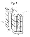
- the volume of the atmosphere in which an EM radiation path modifying component is required to be created can be considered as a cell matrix 10 comprised of M rows and N columns or layers of 'cells' 12, wherein a cell is simply a predefined three-dimensional portion of the matrix.
- each cell is identical in size and shape, but this is not essential, and the present invention is not necessarily intended to be limited in this regard.
- the number of cells in the vertical dimension of the cell matrix may vary.
- the cell matrix may be of any desired size, shape and number of cells.
- the three dimensional structure of an EM radiation path modifying device can be defined in terms of a number of cells 12 in a desired configuration, and it is these cells that will then be targeted by the laser source in order to effect the desired change in their respective properties, i.e. by heating and/or ionisation thereof.
- some aspects of the present invention may operate on the principle that by providing a volume of air that is warmer than the air around it, that volume of air can cause refraction of a beam of electromagnetic radiation as it passes through, in a manner similar to a convergent or divergent lens.
- Ionised air has reflective properties over a range of electromagnetic radiation wavelengths, such properties being a function of density and the type of ionisation created.
- some aspects of the present invention operate on the principle that by ionising a volume of air can cause it to reflect a beam of electromagnetic radiation as it hits that volume, in a manner similar to a mirror or similarly reflective device.
- a mixture of the two principles can be used to create a diffractive element.
- a three dimensional atmospheric spatial radiation modulator can be created using a high power electromagnetic radiation source.
- a pulsed power laser PPL
- CW continuous wave
- the laser system(s) is/are configured to selectively heat or ionise the atmosphere, thus changing its refractive index and electromagnetic properties such that electromagnetic energy passing through the heated cells is refracted and/or electromagnetic energy hitting the ionised cells is reflected.
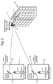
- apparatus comprises at least one laser source 14 mounted in an enclosure 15.
- the laser source 14 is a pulsed power laser source configured to emit high power laser pulses toward the cell matrix 10 via a laser transparent aperture 16.
- An optically reflective device, i.e. mirror, 18 is mounted on a dual-axis actuator (not shown) in the main laser output path, the actuator being communicably coupled with a control system that is configured to cause the actuator (and, therefore, the mirror 18) to move thereby to selectively direct the laser output through the aperture 16 toward selected cells 12 of the matrix 10.
- the control system may, for example, be configured to cause the laser output to be scanned across the cell matrix providing a pulse (or more than one pulse) to each selected cell, either via a raster pattern or a pattern optimised to suit the type of atmospheric component required to be created and its operational requirements.
- the laser pulse is self-focussing by means of the 'Kerr' effect, thereby enabling it to deliver enough concentrated power to heat or ionise the cell at which it is directed.
- the Kerr effect is a change in the refractive index of a material in response to an applied electric field.
- its electric field is sufficiently high to change the refractive index of the air.
- the cross-sectional area of the pulse (perpendicular to the direction of propagation) can be thought of as shrinking with distance (due to the differences in refractive index), thus bringing the pulse to an intense focus at some point down range of the laser, in this case at the selected cell.
- This intense focus is of sufficiently high intensity to heat or ionise the cell to change its refractive index and/or other EM radiation path modifying properties.
- One or more pulses may be provided per cell, dependent upon the desired effect and environmental conditions. It may also be necessary to periodically re-supply laser pulses to all selected cells to maintain the required change in refractive index and/or ionisation for as long as the atmospheric component is required, as once the laser power is removed from a cell, the air therein will very quickly return to its normal (unheated or non-ionised) state.
- two (or more) CW (continuous wave) laser sources 20, 22 may be provided in respective enclosures 24, 26, each having a laser transparent aperture 28, 30 therein.
- each laser system is provided with a mirror 32, 34 mounted on a dual-axis actuator (not shown) communicably coupled to a control system (not shown). Operation of the system is similar, in principle, to that described previously with reference to Figure 3 of the drawings except, in this case, two (or more) spatially separated CW lasers (which may be mounted on the same platform or across different platforms) are used to selectively heat/ionise the atmosphere in each required cell.
- Such scanning may be performed on the basis of a control system configured to maintain a predetermined spatial separation and orientation between the atmospheric component and the electromagnetic radiation source.
- Such scanning may be performed using a control system configured to direct the source(s) at specific coordinates corresponding to specific respective locations within the atmosphere.
- a beam splitter could be employed to split a laser beam into numerous new paths corresponding to the configuration of a plurality of respective cells to be targeted.
- a plurality of such cells could be targeted simultaneously, without the need for scanning a single laser path across the cell matrix.
- an exemplary embodiment of the present invention may be employed to create an atmospheric spatial radiation modulator 40 comprised of a plurality of diametrically spaced apart concentric rings 42.
- the rings 42 may be comprised of ionised (reflective) cells or they may comprised of heated (refractive) cells, in which case each ring may comprise an annulus having, for example, a double concave cross section (thereby making those regions diverging in respect of an incoming electromagnetic signal).
- the central, substantially circular region 44 is unchanged, i.e. not ionised or heated and, therefore, normally transmissive according to the atmospheric conditions in which the element has been created.
- the resultant atmospheric element has the effect of blocking, or diverging, some portions of an incoming electromagnetic beam so as to alter the transverse spatial structure thereof, as shown. It will be appreciated that any number of different modulator patterns may be achieved in this manner and the present invention is not necessarily intended to be limited in this regard. However, it will also be appreciated that the degree of delay in the resultant spatially modulated signal can be increased by increasing the so-called numerical aperture of the atmospheric modulator.
- the central region may, in fact, be ionised or heated in the manner described above such that it operates as an atmospheric centre stop 44a, thereby increasing the numerical aperture of the atmospheric modulator and thus increasing the propagation delay applied to an incoming electromagnetic signal. It can be seen, therefore, that the propagation delay applied to the incoming electromagnetic beam can be selected and controlled by the size and configuration of the atmospheric modulator, in the same way as it could be selected during the design of a physical spatial modulator.
- an apparatus in accordance with an exemplary embodiment of the present invention for creating an atmospheric spatial radiation modulator comprises a control module 100 communicably coupled to, for example, a dual-axis actuator on which a reflective component is mounted within a laser system such as that described above with reference to Figures 2 and 3 of the drawings.
- a laser system may, for example, be mounted in or on an airborne platform such as a manned aircraft or UAV.
- the control module 100 comprises a processor 102 communicably coupled to a database 104.
- the database has stored therein data representative of one or more cell matrices, representative of respective atmospheric volumes, and the cells therein that need to be 'populated' (i.e. heated or ionised) in order to construct a respective three-dimensional atmospheric spatial radiation modulator. Such data may also include information as to the degree of ionisation/heating required to be maintained in order to achieve the required spatial modulating characteristics of the element. It will be appreciated that the database may simply include a single 'template' or populated cell matrix, bespoke to the platform or application in which the respective atmospheric element is to be used. However, in alternative exemplary embodiments, the database may include a plurality of different such templates from which a required atmospheric modulator can be selected for use, as required.
- the processor 102 includes an input and an interface 106 for receiving an actuation signal indicative that an atmospheric modulator is required to be created, together with data representative of the size and orientation of the required component, and data representative of the position and orientation of the atmospheric component relative to the platform on which the apparatus is mounted, the electromagnetic radiation path to be spatially modified and/or the laser source used to create the atmospheric modulator.
- the actuation signal and accompanying data may be manually entered by an operative, but may equally be automatically generated in response to detection of an electromagnetic signal required to be intercepted by the platform.
- a module may be provided that, not only detects an incoming signal, but also tracks it as it moves relative to the platform, or the platform moves relative thereto, and generates data that can be used to change the relative position and orientation of the atmospheric modulator so as to ensure that it remains within the path of the incoming signal for as long as it is required to intercept it.
- the processor 102 in response to the actuation signal, searches the database 104 for the populated cell matrix data corresponding to the atmospheric modulator required to be created, and retrieves the associated data.
- a transformation module 108 is provided, which transforms the matrix cell data onto data representative of the real atmospheric matrix cell within which the spatial radiation modulator is to be created, both in terms of size and orientation thereof, and determines precise coordinates for the location of each real atmospheric cell relative to the corresponding respective cell of the stored matrix (and also relative to the platform on which the apparatus is mounted, the electromagnetic signal to be intercepted and/or the laser source used to create the atmospheric modulator), and a mapping module 110 maps the respective population data from the stored cell matrix onto the data representative of the real atmospheric cell matrix accordingly.
- the processor now knows the precise physical location of each cell in the real atmospheric cell matrix and the cell 'population' pattern required to create the atmospheric modulator.
- data is converted, by a signal processing module 112, into a scanning pattern comprised of a pattern of actuation signals configured to move and actuate the laser beam(s) in order to selectively heat/ionise the real atmospheric cell matrix in the required pattern (and to the required degree) to create the three-dimensional atmospheric spatial modulator.
- the actuation signals are configured to control the power and beam steering of the laser source(s) to heat/ionise each selected cell as required.
- an atmospheric component monitoring system 116 may be provided within, or communicably coupled to, the control module 100.
- the atmospheric component monitoring system 116 may, for example, comprise a low power laser of a suitable wavelength (as will be apparent to a person skilled in the art) to detect atmospheric effects.
- the monitoring system 116 may form part of a feedback loop with the signal processing module 112 to enable the actuation signals to be adjusted to compensate for atmospheric distortion.
- the apparatus may comprise a quality monitoring module for monitoring the performance (i.e.
- the properties and characteristics) of the atmospheric spatial modulator against a predefined set of desired criteria and generating signals to dynamically adjust beam steering and/or power of the electromagnetic radiation source so as to reduce or eliminate deviation of the properties and characteristics of the atmospheric modulator from that which is defined by the predefined criteria.
- Such deviation may be caused by atmospheric distortion or otherwise.
- successive and/or continuous 'fine tuning' of the atmospheric modulator is facilitated to create and maintain an atmospheric modulator having consistently desired characteristics and quality.
- the control system mounted on an aerial platform 200 may be configured to create, in the manner described above, a large atmospheric spatial modulator 202 (using on-board laser sources 201) at a location and orientation within the propagation path of an adversary signal 204 to ensure that transverse spatial modulation thereof is achieved.
- signal 204a reaches the ECM system on-board the aerial platform (or indeed on a platform remote therefrom in some configurations), signal has been delayed and a counter signal can be emitted for the purposes of disrupting or deceiving the adversary systems, in any known manner.
- the incoming signal may simply be permitted to be returned, unaltered, to an adversary detection system.
- the adversary detection system will be deceived as to the position and/or relative distance at which the aerial platform 200 is located.
- control system may be configured to create multiple atmospheric electromagnetic radiation path modifying elements in the path of the incoming signal, the atmospheric elements being configured and oriented to increase the path length of the incoming signal between its source and the platform and, thereby further increase the propagation delay.
Landscapes
- Physics & Mathematics (AREA)
- Engineering & Computer Science (AREA)
- Nonlinear Science (AREA)
- General Physics & Mathematics (AREA)
- Radar, Positioning & Navigation (AREA)
- Remote Sensing (AREA)
- Computer Networks & Wireless Communication (AREA)
- Optics & Photonics (AREA)
- General Engineering & Computer Science (AREA)
- Chemical & Material Sciences (AREA)
- Ceramic Engineering (AREA)
- Crystallography & Structural Chemistry (AREA)
- Lasers (AREA)
Priority Applications (1)
| Application Number | Priority Date | Filing Date | Title |
|---|---|---|---|
| EP15179605.9A EP3128340A1 (fr) | 2015-08-04 | 2015-08-04 | Procédé et appareil pour modifier un signal électromagnétique |
Applications Claiming Priority (1)
| Application Number | Priority Date | Filing Date | Title |
|---|---|---|---|
| EP15179605.9A EP3128340A1 (fr) | 2015-08-04 | 2015-08-04 | Procédé et appareil pour modifier un signal électromagnétique |
Publications (1)
| Publication Number | Publication Date |
|---|---|
| EP3128340A1 true EP3128340A1 (fr) | 2017-02-08 |
Family
ID=53783107
Family Applications (1)
| Application Number | Title | Priority Date | Filing Date |
|---|---|---|---|
| EP15179605.9A Ceased EP3128340A1 (fr) | 2015-08-04 | 2015-08-04 | Procédé et appareil pour modifier un signal électromagnétique |
Country Status (1)
| Country | Link |
|---|---|
| EP (1) | EP3128340A1 (fr) |
Citations (2)
| Publication number | Priority date | Publication date | Assignee | Title |
|---|---|---|---|---|
| US5415156A (en) * | 1993-06-02 | 1995-05-16 | Stirbl; Robert C. | Method using solar energy |
| US20090171477A1 (en) * | 2007-12-10 | 2009-07-02 | Nayfeh Taysir H | Laser generated synthetic mega scale aperture for solar energy concentration and harnessing |
-
2015
- 2015-08-04 EP EP15179605.9A patent/EP3128340A1/fr not_active Ceased
Patent Citations (2)
| Publication number | Priority date | Publication date | Assignee | Title |
|---|---|---|---|---|
| US5415156A (en) * | 1993-06-02 | 1995-05-16 | Stirbl; Robert C. | Method using solar energy |
| US20090171477A1 (en) * | 2007-12-10 | 2009-07-02 | Nayfeh Taysir H | Laser generated synthetic mega scale aperture for solar energy concentration and harnessing |
Non-Patent Citations (2)
| Title |
|---|
| BRIAN W. NEISWANDER ET AL: "Plasma Lens for Optical Path Difference Control", AIAA JOURNAL, vol. 50, no. 1, 1 January 2012 (2012-01-01), pages 123 - 130, XP055212822, ISSN: 0001-1452, DOI: 10.2514/1.J051175 * |
| DANIEL GIOVANNI ET AL.: "Spatially structured photons that travel in free space slower than the speed of light", SCIENCE, vol. 347, February 2015 (2015-02-01), pages 357 - 860 |
Similar Documents
| Publication | Publication Date | Title |
|---|---|---|
| AU2016245376B2 (en) | A weapons counter measure method and apparatus | |
| EP3281402B1 (fr) | Appareil capteur à longue portée et procédé permettant de fournir un tel appareil | |
| US10935642B2 (en) | Detection counter measure method and apparatus | |
| US20180143303A1 (en) | Method and apparatus for computational ghost imaging | |
| EP3128340A1 (fr) | Procédé et appareil pour modifier un signal électromagnétique | |
| EP3631499B1 (fr) | Système d'armement | |
| EP3079277A1 (fr) | Appareil et procédé pour des communications à distance | |
| US10437130B2 (en) | Method and apparatus for simulating electromagnetic radiation path modifying devices | |
| EP3128341A1 (fr) | Procédé et appareil de mesure à compteur de détection | |
| EP3128343A1 (fr) | Procédé et appareil de contre-mesures d'armes | |
| EP3078982A1 (fr) | Appareil et procédé de détection à distance | |
| GB2537183A (en) | A detection counter measure method and apparatus | |
| EP3079008A1 (fr) | Procédé et appareil permettant de simuler des dispositifs de modification de trajectoire de rayonnement électromagnétique | |
| GB2565200A (en) | Weapon system | |
| GB2537184A (en) | A weapon counter measure method and apparatus | |
| GB2540115A (en) | Method and apparatus for simulating electromagnetic radiation path modifying devices | |
| RU2794379C1 (ru) | Автоматическая установка для активной защиты воздушного пространства от птиц и малых беспилотных летательных аппаратов | |
| EP3078986A1 (fr) | Procédé et appareil pour une imagerie fantôme de calcul | |
| He et al. | A review of research progress in laser jamming and antijamming technology | |
| EP3128284A1 (fr) | Procédé et appareil permettant de concentrer l'énergie électromagnétique | |
| EP3079354A1 (fr) | Appareil capteur à longue portée et procédé permettant de fournir un tel appareil | |
| Patrick | Pointing and Jitter Control for the USNA Multi-Beam Combining System | |
| GB2537156A (en) | Long range sensor apparatus and method of providing a long range sensor apparatus |
Legal Events
| Date | Code | Title | Description |
|---|---|---|---|
| PUAI | Public reference made under article 153(3) epc to a published international application that has entered the european phase |
Free format text: ORIGINAL CODE: 0009012 |
|
| AK | Designated contracting states |
Kind code of ref document: A1 Designated state(s): AL AT BE BG CH CY CZ DE DK EE ES FI FR GB GR HR HU IE IS IT LI LT LU LV MC MK MT NL NO PL PT RO RS SE SI SK SM TR |
|
| AX | Request for extension of the european patent |
Extension state: BA ME |
|
| STAA | Information on the status of an ep patent application or granted ep patent |
Free format text: STATUS: THE APPLICATION HAS BEEN REFUSED |
|
| 18R | Application refused |
Effective date: 20170225 |