EP3128354A1 - Connecteur d'amortissement des vibrations et utilisation du connecteur d'amortissement de vibrations - Google Patents
Connecteur d'amortissement des vibrations et utilisation du connecteur d'amortissement de vibrations Download PDFInfo
- Publication number
- EP3128354A1 EP3128354A1 EP15179924.4A EP15179924A EP3128354A1 EP 3128354 A1 EP3128354 A1 EP 3128354A1 EP 15179924 A EP15179924 A EP 15179924A EP 3128354 A1 EP3128354 A1 EP 3128354A1
- Authority
- EP
- European Patent Office
- Prior art keywords
- vibration damping
- damping connector
- shock absorbing
- absorbing element
- vibration
- Prior art date
- Legal status (The legal status is an assumption and is not a legal conclusion. Google has not performed a legal analysis and makes no representation as to the accuracy of the status listed.)
- Withdrawn
Links
Images

Classifications
-
- G—PHYSICS
- G02—OPTICS
- G02B—OPTICAL ELEMENTS, SYSTEMS OR APPARATUS
- G02B27/00—Optical systems or apparatus not provided for by any of the groups G02B1/00 - G02B26/00, G02B30/00
- G02B27/64—Imaging systems using optical elements for stabilisation of the lateral and angular position of the image
- G02B27/646—Imaging systems using optical elements for stabilisation of the lateral and angular position of the image compensating for small deviations, e.g. due to vibration or shake
-
- F—MECHANICAL ENGINEERING; LIGHTING; HEATING; WEAPONS; BLASTING
- F16—ENGINEERING ELEMENTS AND UNITS; GENERAL MEASURES FOR PRODUCING AND MAINTAINING EFFECTIVE FUNCTIONING OF MACHINES OR INSTALLATIONS; THERMAL INSULATION IN GENERAL
- F16F—SPRINGS; SHOCK-ABSORBERS; MEANS FOR DAMPING VIBRATION
- F16F15/00—Suppression of vibrations in systems; Means or arrangements for avoiding or reducing out-of-balance forces, e.g. due to motion
- F16F15/02—Suppression of vibrations of non-rotating, e.g. reciprocating systems; Suppression of vibrations of rotating systems by use of members not moving with the rotating systems
- F16F15/04—Suppression of vibrations of non-rotating, e.g. reciprocating systems; Suppression of vibrations of rotating systems by use of members not moving with the rotating systems using elastic means
- F16F15/08—Suppression of vibrations of non-rotating, e.g. reciprocating systems; Suppression of vibrations of rotating systems by use of members not moving with the rotating systems using elastic means with rubber springs ; with springs made of rubber and metal
-
- G—PHYSICS
- G01—MEASURING; TESTING
- G01Q—SCANNING-PROBE TECHNIQUES OR APPARATUS; APPLICATIONS OF SCANNING-PROBE TECHNIQUES, e.g. SCANNING PROBE MICROSCOPY [SPM]
- G01Q30/00—Auxiliary means serving to assist or improve the scanning probe techniques or apparatus, e.g. display or data processing devices
- G01Q30/02—Non-SPM analysing devices, e.g. SEM [Scanning Electron Microscope], spectrometer or optical microscope
- G01Q30/025—Optical microscopes coupled with SPM
-
- G—PHYSICS
- G02—OPTICS
- G02B—OPTICAL ELEMENTS, SYSTEMS OR APPARATUS
- G02B21/00—Microscopes
- G02B21/36—Microscopes arranged for photographic purposes or projection purposes or digital imaging or video purposes including associated control and data processing arrangements
- G02B21/362—Mechanical details, e.g. mountings for the camera or image sensor, housings
-
- G—PHYSICS
- G02—OPTICS
- G02B—OPTICAL ELEMENTS, SYSTEMS OR APPARATUS
- G02B7/00—Mountings, adjusting means, or light-tight connections, for optical elements
- G02B7/02—Mountings, adjusting means, or light-tight connections, for optical elements for lenses
- G02B7/14—Mountings, adjusting means, or light-tight connections, for optical elements for lenses adapted to interchange lenses
-
- F—MECHANICAL ENGINEERING; LIGHTING; HEATING; WEAPONS; BLASTING
- F16—ENGINEERING ELEMENTS AND UNITS; GENERAL MEASURES FOR PRODUCING AND MAINTAINING EFFECTIVE FUNCTIONING OF MACHINES OR INSTALLATIONS; THERMAL INSULATION IN GENERAL
- F16F—SPRINGS; SHOCK-ABSORBERS; MEANS FOR DAMPING VIBRATION
- F16F2226/00—Manufacturing; Treatments
- F16F2226/04—Assembly or fixing methods; methods to form or fashion parts
- F16F2226/042—Gluing
-
- F—MECHANICAL ENGINEERING; LIGHTING; HEATING; WEAPONS; BLASTING
- F16—ENGINEERING ELEMENTS AND UNITS; GENERAL MEASURES FOR PRODUCING AND MAINTAINING EFFECTIVE FUNCTIONING OF MACHINES OR INSTALLATIONS; THERMAL INSULATION IN GENERAL
- F16F—SPRINGS; SHOCK-ABSORBERS; MEANS FOR DAMPING VIBRATION
- F16F2230/00—Purpose; Design features
- F16F2230/0005—Attachment, e.g. to facilitate mounting onto confer adjustability
-
- F—MECHANICAL ENGINEERING; LIGHTING; HEATING; WEAPONS; BLASTING
- F16—ENGINEERING ELEMENTS AND UNITS; GENERAL MEASURES FOR PRODUCING AND MAINTAINING EFFECTIVE FUNCTIONING OF MACHINES OR INSTALLATIONS; THERMAL INSULATION IN GENERAL
- F16F—SPRINGS; SHOCK-ABSORBERS; MEANS FOR DAMPING VIBRATION
- F16F2234/00—Shape
- F16F2234/04—Shape conical
-
- G—PHYSICS
- G02—OPTICS
- G02B—OPTICAL ELEMENTS, SYSTEMS OR APPARATUS
- G02B21/00—Microscopes
- G02B21/0004—Microscopes specially adapted for specific applications
- G02B21/0088—Inverse microscopes
Definitions
- the present invention relates to a vibration damping connector for reducing vibrations between a vibration prone system and an optical imaging system. Furthermore, use of the vibration damping connector in an optical system is disclosed.
- the connector may attach a vibration prone system, for example an Atomic Force Microscope (AFM), with a charge-coupled device (CCD) digital camera system with a cooling fan or an optical imaging system with motorized components such as e.g. a spinning disk.
- AFM Atomic Force Microscope
- CCD charge-coupled device
- the connector is usually according to a known standard for optical imaging sensors that dictates the design of the mount shape and sensor distance with respect to the optical mount in optical imaging.
- the connectors are according to the ISO 10935:2009.
- the system or the optical imaging system is exposed to mechanical vibrations and/or noise, for example from the systems themselves or from the surrounding environment. This reduces the quality of the image and subsequently the data to be extracted.
- One way to improve the quality may for example by using complex computer programs. However, there is a desire to improve the quality in other ways.
- the object of the present invention is to provide a vibration damping connector that overcomes the above issues.
- the invention is based on the insight that by having at least a two part connector where the parts are connected via shock absorbing elements vibrations and noise can be absorbed by the connector itself.
- the invention relates to a vibration damping connector for reducing vibrations between a vibration prone system and an optical imaging system, said vibration damping connector comprising
- vibrations can be absorbed by the shock absorbing elements.
- the vibrations from the vibration prone system are reduced or eliminated by the vibration damping connector such that the vibrations, which otherwise would transfer to the optical imaging system and cause reduced imaging quality are less than using a standard C-mount adapter/connector.
- the vibration damping connector may connect an optical inverted microscope used in research, having an atomic force microscope (AFM) mounted on top of it, with a charge-coupled device (CCD) digital camera system with a cooling fan or an optical imaging system with motorized components such as. a spinning disk.
- AFM atomic force microscope
- CCD charge-coupled device
- a correct distance of the optical sensor may be provided with respect to the optical instrument it is attached to.
- the two parts i.e. the first and the second part, arranged with shock absorbing elements between them and in the fastening connection, i.e. when the fastening device presses the first part to the second part via the second shock absorbing element the two parts may be separated from each other, i.e. not in contact with each other. This provides electrical shielding.
- the at least one first shock absorbing element may be one large element or several smaller elements.
- the first and the second part may be made of metal, for example aluminium or stainless steel. However any other suitable material may be used.
- the parts may also be galvanized in black to avoid internal reflections of the bare material that would compromise image formation quality.
- the vibration damping connector may comprise several fastening devices arranged around the vibration damping connector or only one fastening device. If several fastening devices are used, they are preferably evenly distributed around the vibration damping connector in order to evenly distribute the pressure around the vibration damping connector. If one fastening device is used, it may be designed such that it evenly presses the two parts together. The centre axes of the two parts should be aligned.
- said fastening device comprises a first fastening portion attached to said first portion and a second fastening portion attached to said second portion and said first fastening portion and said second fastening portion are in contact with said second shock absorbing element and limits displacement along the central axis between of the first part and the second part.
- the first and the second fastening portions which are in contact with the second shock absorbing element prevent the two parts from separating. If there are several fastening devices they are preferably evenly arranged around the vibration damping connector such that the parts are pressed evenly together all around the vibration damping connector. This way it is ensured that the centre lines of each part are aligned. If they are not aligned the image formed on the imaging system may be cut/distorted This since optical systems that do not have their "optical axis" aligned, suffer from various optical aberrations in the final image.
- said first and/or said second shock absorbing element is made of a shock absorbing material.
- the shock absorbing material may for example be silicone rubber, silicone gel, urethane, natural rubber, soft rubber, neoprene, styrene-butadiene rubber compound, polyethylene foam or Polyurethane foam. The choice depends on material compression, weight, and resistance to twist and shearing.
- the first and the second shock absorbing element may be made of the same material or different materials.
- the first shock absorbing element may be a pad.
- said first part comprises an inner conical shape and said second part comprises a matching outer conical shape.
- said first part comprises an outer conical shape and said second part comprises a matching inner conical shape.
- the matching conical shapes facilitate the assembly of the vibration damping connector. This since the conical shape guides the two parts into a correct position.
- the conical design together with the first shock absorbing element also facilitates that the two parts are arranged in a correct position in the direction of the central axis in order to get a correct distance of the optical sensor with respect to the optical instrument it is attached to.
- said first part is a female part and said second part is a male part.
- said first part is a male part and said second part is a female part.
- said first part and said second part are out of contact from each other. This provides electrical shielding.
- said first shock absorbing element is arranged to said first part by using adhesive.
- said first shock absorbing element is arranged to said second part by using adhesive.
- said second part comprises an end which is c-mount compatible in order to connect to said vibration prone system. That is, the end or the end portion of the second part is made in accordance with the standard which specifies the dimensions of a thread mount connection type C for a microscope imaging exit port (other than a monocular or binocular viewing tube) and the position of the image plane, The standard is at the time of filing the application ISO 10935:2009.
- the vibration damping connector described above may be used in an optical system between a vibration prone system and an optical imaging system.
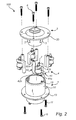
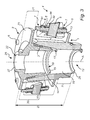
- Figs. 1 , 2 and 3 show a vibration damping connector 100, which can take up vibration and/or noise between two systems.
- the Figs. 1 , 2 and 3 will be described together.
- the vibration damping connector 100 may for example take up vibration and/or noise between a vibration prone system, for example a differential spinning disk, and/or an optical Imaging system, for example an microscope.
- the vibration damping connector 100 comprises a first part 1 and a second part 2, where the second part 2 is inserted into the first part 1 along a common central axis A.
- the first part 1 is a female part 1 and the second part 2 is a male part 2.
- the first part 1 comprises a main portion 10 and an end portion 11.
- the main portion 10 comprises an outer cylindrical shape with a through hole 12 (see Fig. 3 ) having a first portion 14, a second portion 15 and a third portion 16.
- the first portion 14 comprises a tapering shape, i.e. an inner conical shape. In this first portion 14 the second part 2 will be received.
- the second portion 15 is formed by an inner flange 17 which defines an opening 18 which has a smaller diameter than the largest and smallest diameter of the first conical portion 14.
- the third portion 16 is a cylindrical portion.
- the end portion 11 is compatible with an apparatus, for example an optical imaging system and connects the vibration damping connector 100 with the apparatus. This can be done in any known suitable way.
- the second part 2 comprises a main portion 20 and an end portion 21.
- the main portion 20 of the second part 2 comprises an outer conical shape, which is matching the first portion 14, i.e. the inner conical shape of the main portion 10 of the first portion 1.
- the end portion 21 of the second part 2 is according to the standard which specifies the dimensions of a thread mount connection type C for a microscope imaging exit port (other than a monocular or binocular viewing tube) and the position of the image plane, i.e. ISO 10935:2009.
- the main portion 20 and the end portion 21 of the second part 2 is also provided with a through hole 22.
- the inner design, i.e. the inner diameters and distances, of the vibration damping connector 100, i.e. the through hole 25, is dependent on the microscope it shall be attached to.
- the inner design of the vibration damping connector 100 may be adapted to different microscopes.
- the inner design restricts light rays hitting the microscope optical detectors (e.g. CCD camera or DSD as described in connection with Fig. 4 ). They are referred to in geometrical optics as "optical stops", since they restrict the optical light rays passing through the optical systems. Adaption of the vibration damping connector 100 to different microscope manufacturers will require different "optical stop" designs.
- first shock absorbing elements 3 On the male part 2 are four first shock absorbing elements 3 arranged (see Fig. 2 , only two are shown).
- the four shock absorbing elements are four pads attached to the second part.
- the shock absorbing elements 3 may for example be made of a silicone rubber sheet, a silicone gel sheet, a polyethylene foam sheet, polyurethane foam sheet or an elastomer having dampening material properties.
- the shock absorbing elements 3 are attached to the second part 2 by double-stick tape, may however be glued to the second part 2 or the first part 1 or even loosely arrange between the second part 2 and the first part 1.
- the first shock absorbing elements 3 separate the second part 2 and the first part 1 from each other, i.e. they are not in contact with each other.
- the four first shock absorbing elements are evenly distributed around the vibration damping connector 100.
- the number of first shock absorbing elements is not limited to being four, they may be more or less. For example may it be one which extends all around the second part 2.
- the first part 1 comprises a flange 13 which extends perpendicular to the central axis of the first part.
- the second part 2 comprises a similar flange 23 which is part of the end portion 21 of the second part 2.
- the end surface 26 of the end portion 11 of the first part 1 and the end surface 27 of the end portion 21 of the second part 2 are arranged essentially parallel to each other and they are arranged perpendicular to the centre axis A.
- the end surfaces 26, 27 are arranged at a distance D from each other to provide correct distancing of an optical sensor (for example the DSD) with respect to the optical instrument, for example the optical microscope with AFM attached to it (see Fig. 4 ).
- the distance D is a set distance D, which depends on the optics on either side of the vibration damping device 100
- the fastening devices 4 are evenly distributed around the vibration damping connector 100. They are not limited to being four fastening devices 4, they may be more or less.
- One fastening device 4 comprises a first fastening portion 41.
- the first fastening portion 41 having an L-shape, i.e. two legs 41 a, 41 b attached perpendicular to each other.
- One end of one of legs 41 a of the L-shaped first fastening portion 41 is attached to the flange 13 of the first portion 1 by a fastener 6, i.e. a screw which threadedly engages the first fastening portion 41a.
- the fastening device 4 further comprises a second fastening portion 42 having similar L-shape as the first fastening portion 41.
- One end of the legs 42a of the L-shaped second fastening portion 42 is attached to the flange 23 of the second portion 2 by a fastener 6, i.e. a screw.
- the second leg 41 b of the L-shaped first fastening portion 41 is in contact with a second shock absorbing element 5 and the second leg 42b of the L-shaped second fastening portion 42 is in contact with the same second shock absorbing element 5 opposite the second leg 41 b of the L-shaped first fastening portion 41. They are both in contact with the second shock absorbing element 5 via distance regulators 7 and together they limit displacement along the central axis A between the first part 1 and the second part 2.
- the distance regulators 7 each comprises a nut 9 and a mushroom shaped element 8 having a threaded stem 81 and a head 82.
- the threaded stem 81 protrudes through a hole 44 in the second leg 41 b, 42b of either the first or the second fastening portion 41, 42 such that the head 82 is in contact with the second shock absorbing element 5.
- the head 82 is glued to the second shock absorbing element 5.
- the nut 9 threadedly engages the threaded stem 81 of the mushroom shaped element 8. Depending on how much a nut 9 is screwed onto the threaded stem 81 the pressure and the distance between the first and the second part can be regulated.
- the distance regulators 7 also influence the overall damping factor.
- the second shock absorbing element 5 may be made of silicone rubber, silicone gel, urethane, natural rubber, soft rubber, neoprene or styrene-butadiene rubber compound or any other suitable material.
- the second shock absorbing element 5 has a conical shape.
- the head 82 of the mushroom shaped element 8 which is in contact with the second leg 42b of the second fastening portion has a diameter, which is essentially equal with the larger diameter end of the second conical shaped absorbing element 5.
- the head 82 of the mushroom shaped element 8 which is in contact with the second leg 41 b of the first fastening portion has a diameter, which is essentially equal with the smaller diameter end of the second conical shaped absorbing element.
- the second shock absorbing element 5 is not limited to being conical, it may have any suitable shape.
- the diameter or the outer contour of the head 82 of the mushroom shaped element is not limited to have the same dimension as the second shock absorbing element 5.
- the vibration damping connector 100 When one of the systems, to which the vibration damping connector 100 may be connected to, is exposed to vibration or noise or creates the vibrations itself the vibration damping connector 100 will absorb the vibration or noise through the first and the second shock absorbing elements 3, 5.
- the amount of vibration the vibration damping connector 100 can absorb depends on the material of the shock absorbing elements, the shape of the shock absorbing elements and the number of shock absorbing elements.
- first part 1 is a female part and the second part 2 is a male part.
- first part 1 may be the male part and the second part 2 may be the female part.
- the vibration damping connector 100 could for example be used in a combined microscopy platform 200 (see Fig. 4 ) based on fluorescence optical sectioning microscopy through aperture correlation microscopy with a Differential Spinning Disk (DSD) 201 and nano-mechanical mapping with an Atomic Force Microscope (AFM) 202.
- DSD Differential Spinning Disk
- AFM Atomic Force Microscope
- the illumination scheme of the DSD microscope unit contrary to standard single or multi-point confocal microscopes, provides a time-independent illumination of the AFM cantilever. This enables an easy integration of simultaneously recorded fluorescence microscopy data with scanning probe microscopy data acquired with standard probes.
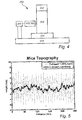
- FIG. 4 schematically displays the experimental set-up for integration of a DSD imaging platform 201 and an advanced bioscience AFM system 202 capable of QI (Quantitative Imaging (JPK Instruments, Germany).
- Different connectors 100, 300 connecting the DSD 201 with the inverted optical microscope 205 having an Atomic Force Microscope (AFM) 202 mounted on top of it were used when making the tests.
- One test was made using the vibration damping connector 100 (C-mount 2) described in connection with the Figs. 1-3 .
- a dedicated condenser lens (not shown) with an extra long working distance of 75mm (T1-CELWD ELWD, Nikon Instruments Europe B.V., Amsterdam, The Netherlands) was installed to comply with the height of the AFM unit.
- Fast automated objective focus control and scanning is provided by a piezo unit (P-725 PIFOC®, Physik Instrument, Düsseldorf, Germany) (not shown).
- P-725 PIFOC® Physik Instrument, Düsseldorf, Germany
- For optimal fluorescence detection a high numerical aperture objective (not shown) has been used for the measurements reported (CFI Plan Apo VC 60X Oil, Nikon Instruments Europe B.V., Amsterdam, The Netherlands).
- a metal halide light source (not shown) with built-in fluorescence excitation filter (AMH-200, Andor Technology, Southern, Northern Ireland) wheel provides excitation light for the DSD unit (DSD generation-1, Andor Technology, Harbor, Northern Ireland).
- An interline CCD camera (Andor Clara, Andor Technology, Southern, Northern Ireland) (not shown) was used for DSD image capture.
- a standard monochrome CCD camera (ProgRes®MFCool, Jenoptik, Jena, Germany) (not shown) was coupled to a microscope port for AFM cantilever laser spot alignment.
- the experimental set-up suffers from AFM cantilever perturbation induced by the Differential Spinning Disk (DSD) unit 201 which influence the quality of the AFM image.
- This perturbation has been traced to originate entirely from the DSD spinning disk motion.
- This perturbation can be reduced by using the vibration damping connector 100 described in connection with Figs. 1 to 3 which at one end is connected to the Differential Spinning Disk (DSD) 201 and at the other end with the inverted optical microscope 205 having the atomic force microscope (AFM) 202 mounted on top of it, as shown in Fig. 4.
- the vibrations have been reduced using the vibration damping connector 100 described in connection with Figs 1-3 .
- the height values of the surface being measured can be obtained.
- the mica surface height measured by the AFM over a distance of 250 nm.
- the values were joined to be obtained on the same graphic.
- the C-mount 2 reduces the noise in the AFM image to a larger extent as compared to when C-mount 1 was tested.
Landscapes
- Physics & Mathematics (AREA)
- Engineering & Computer Science (AREA)
- General Physics & Mathematics (AREA)
- Optics & Photonics (AREA)
- General Engineering & Computer Science (AREA)
- Chemical & Material Sciences (AREA)
- Combustion & Propulsion (AREA)
- Mechanical Engineering (AREA)
- Aviation & Aerospace Engineering (AREA)
- Acoustics & Sound (AREA)
- Multimedia (AREA)
- Radiology & Medical Imaging (AREA)
- Nuclear Medicine, Radiotherapy & Molecular Imaging (AREA)
- General Health & Medical Sciences (AREA)
- Health & Medical Sciences (AREA)
- Analytical Chemistry (AREA)
- Vibration Prevention Devices (AREA)
- Microscoopes, Condenser (AREA)
Priority Applications (4)
| Application Number | Priority Date | Filing Date | Title |
|---|---|---|---|
| EP15179924.4A EP3128354A1 (fr) | 2015-08-06 | 2015-08-06 | Connecteur d'amortissement des vibrations et utilisation du connecteur d'amortissement de vibrations |
| PCT/EP2016/066521 WO2017021108A1 (fr) | 2015-08-06 | 2016-07-12 | Raccord d'amortissement de vibration et utilisation du raccord d'amortissement de vibration |
| CN201680044986.XA CN107850172B (zh) | 2015-08-06 | 2016-07-12 | 振动阻尼连接器及其用途 |
| US15/743,116 US10379372B2 (en) | 2015-08-06 | 2016-07-12 | Vibration damping connector and use of the vibration damping connector |
Applications Claiming Priority (1)
| Application Number | Priority Date | Filing Date | Title |
|---|---|---|---|
| EP15179924.4A EP3128354A1 (fr) | 2015-08-06 | 2015-08-06 | Connecteur d'amortissement des vibrations et utilisation du connecteur d'amortissement de vibrations |
Publications (1)
| Publication Number | Publication Date |
|---|---|
| EP3128354A1 true EP3128354A1 (fr) | 2017-02-08 |
Family
ID=53938094
Family Applications (1)
| Application Number | Title | Priority Date | Filing Date |
|---|---|---|---|
| EP15179924.4A Withdrawn EP3128354A1 (fr) | 2015-08-06 | 2015-08-06 | Connecteur d'amortissement des vibrations et utilisation du connecteur d'amortissement de vibrations |
Country Status (4)
| Country | Link |
|---|---|
| US (1) | US10379372B2 (fr) |
| EP (1) | EP3128354A1 (fr) |
| CN (1) | CN107850172B (fr) |
| WO (1) | WO2017021108A1 (fr) |
Families Citing this family (6)
| Publication number | Priority date | Publication date | Assignee | Title |
|---|---|---|---|---|
| CA3029673A1 (fr) * | 2016-06-29 | 2018-01-04 | Superior Industries, Inc. | Broyeur a percussion a arbre vertical |
| TWI655491B (zh) * | 2018-04-18 | 2019-04-01 | 大陽科技股份有限公司 | 鏡頭驅動模組、鏡頭驅動模組的製造方法、攝影系統與手機裝置 |
| DE102018005492B4 (de) * | 2018-07-11 | 2026-03-19 | Sumitomo Riko Company Limited | Schwingungstilger und Verfahren zur Herstellung eines Schwingungstilgers |
| US10743433B2 (en) * | 2018-10-15 | 2020-08-11 | Dell Products L.P. | Modular floating mechanism design for cable blind mating at server infrastructure |
| US12313905B1 (en) * | 2022-03-15 | 2025-05-27 | Bae Systems Space & Mission Systems Inc. | Monolithic two-axis flexure with center hole feature |
| CN119802150A (zh) * | 2024-10-09 | 2025-04-11 | 陕西飞机工业有限责任公司 | 一种用于航摄相机的隔振系统 |
Citations (7)
| Publication number | Priority date | Publication date | Assignee | Title |
|---|---|---|---|---|
| US2924419A (en) * | 1953-11-06 | 1960-02-09 | United Carr Fastener Corp | Anti-vibration mounting device |
| US3474992A (en) * | 1966-07-06 | 1969-10-28 | Optische Werke Steinheil Gmbh | Resiliently yielding damped mounting |
| US20030183995A1 (en) * | 2001-07-05 | 2003-10-02 | The Boeing Company | Elastomeric suspension and mounting system |
| EP1726846A1 (fr) * | 2005-05-19 | 2006-11-29 | Coretronic Corporation | Dispositif anti-vibratoire et procédé associé |
| US20130050515A1 (en) * | 2011-08-23 | 2013-02-28 | Fu-Yuan Wu | Method and structure for suppressing resonance in an anti-shake lens focusing module |
| US20130286473A1 (en) * | 2012-04-27 | 2013-10-31 | Olympus Corporation | Inverted microscope |
| US20130299669A1 (en) * | 2010-11-23 | 2013-11-14 | Philippe Laurens | Vibration isolating device |
Family Cites Families (11)
| Publication number | Priority date | Publication date | Assignee | Title |
|---|---|---|---|---|
| SE524074C2 (sv) * | 2000-06-02 | 2004-06-22 | Forsheda Ab | Anordning för dämpning av vibrationer hos en vibrationsyta och metoder för montering av en sådan anordning |
| US7503552B2 (en) * | 2004-06-18 | 2009-03-17 | Basf Corporation | Mount assembly |
| US7487958B2 (en) * | 2005-05-10 | 2009-02-10 | Shu-Lung Wang | Anti-vibration mechanism for dental impression material mixer |
| JP4976056B2 (ja) * | 2006-06-05 | 2012-07-18 | 株式会社ブリヂストン | 防振装置 |
| USD559083S1 (en) * | 2007-01-26 | 2008-01-08 | Arkon Resources, Inc. | Adapter plate |
| DE102009005954B4 (de) * | 2009-01-20 | 2010-10-21 | Carl Zeiss Smt Ag | Dämpfungsvorrichtung |
| EP2532918B1 (fr) * | 2010-02-04 | 2018-06-27 | Bridgestone Corporation | Dispositif amortisseur de vibrations |
| WO2013192370A2 (fr) * | 2012-06-21 | 2013-12-27 | Google Inc. | Amortisseurs de vibrations réglables |
| DE102013018185A1 (de) * | 2013-10-30 | 2015-04-30 | Carl Freudenberg Kg | Lager |
| US9897158B2 (en) * | 2016-06-29 | 2018-02-20 | Caterpillar Inc. | Adapter for an isolation mount design |
| US10125843B2 (en) * | 2016-10-20 | 2018-11-13 | Minus K. Technology, Inc. | Horizontal-motion vibration isolator |
-
2015
- 2015-08-06 EP EP15179924.4A patent/EP3128354A1/fr not_active Withdrawn
-
2016
- 2016-07-12 CN CN201680044986.XA patent/CN107850172B/zh not_active Expired - Fee Related
- 2016-07-12 US US15/743,116 patent/US10379372B2/en not_active Expired - Fee Related
- 2016-07-12 WO PCT/EP2016/066521 patent/WO2017021108A1/fr not_active Ceased
Patent Citations (7)
| Publication number | Priority date | Publication date | Assignee | Title |
|---|---|---|---|---|
| US2924419A (en) * | 1953-11-06 | 1960-02-09 | United Carr Fastener Corp | Anti-vibration mounting device |
| US3474992A (en) * | 1966-07-06 | 1969-10-28 | Optische Werke Steinheil Gmbh | Resiliently yielding damped mounting |
| US20030183995A1 (en) * | 2001-07-05 | 2003-10-02 | The Boeing Company | Elastomeric suspension and mounting system |
| EP1726846A1 (fr) * | 2005-05-19 | 2006-11-29 | Coretronic Corporation | Dispositif anti-vibratoire et procédé associé |
| US20130299669A1 (en) * | 2010-11-23 | 2013-11-14 | Philippe Laurens | Vibration isolating device |
| US20130050515A1 (en) * | 2011-08-23 | 2013-02-28 | Fu-Yuan Wu | Method and structure for suppressing resonance in an anti-shake lens focusing module |
| US20130286473A1 (en) * | 2012-04-27 | 2013-10-31 | Olympus Corporation | Inverted microscope |
Non-Patent Citations (1)
| Title |
|---|
| H. AMICK; M. GENDREAU; T. BUSCH; C. GORDON: "Evolving criteria for research facilities: vibration", PROCEEDING OF SPIE5933, 2005, pages 593303 - 593313 |
Also Published As
| Publication number | Publication date |
|---|---|
| WO2017021108A1 (fr) | 2017-02-09 |
| CN107850172B (zh) | 2020-05-19 |
| US20180231794A1 (en) | 2018-08-16 |
| CN107850172A (zh) | 2018-03-27 |
| US10379372B2 (en) | 2019-08-13 |
Similar Documents
| Publication | Publication Date | Title |
|---|---|---|
| US10379372B2 (en) | Vibration damping connector and use of the vibration damping connector | |
| US20240393221A1 (en) | Apparatus for characterizing particles and method for use in characterizing particles | |
| DE60219360T2 (de) | Bikonvexe festimmersionslinse | |
| KR101600094B1 (ko) | 유리 시트 검사 시스템 | |
| US7636204B1 (en) | 360 degree view imaging system | |
| JPH10506478A (ja) | 細胞学的装置の自動焦点の完全性を点検する装置 | |
| CN101821595B (zh) | 用于测量被聚焦的激光束的测量装置 | |
| CN102043238B (zh) | 四组元高分辨率日夜两用多点变焦距镜头 | |
| Lawrence et al. | The MANIFEST fibre positioning system for the Giant Magellan Telescope | |
| CN212008286U (zh) | 一种医学检测设备的反光镜调节装置 | |
| CN205691843U (zh) | 一种便于反光镜角度调节的安装机构 | |
| CN201740916U (zh) | 一种体视显微镜 | |
| JP2016075509A (ja) | 筒状穴内検査用器具、及びこれを用いた筒状穴内検査装置 | |
| CN203443767U (zh) | 用于检测综合验光仪的辅助定位装置和光学检测系统 | |
| CN115421265A (zh) | 物镜稳定器及光机 | |
| WO2019178093A1 (fr) | Microscopie à image miroir pour collecte accrue | |
| CN209167106U (zh) | 用于矿物鉴定的偏光显微镜用偏光仪 | |
| US9719882B2 (en) | Optical device, optical test bench and optical test method | |
| CN101832911A (zh) | 车载红外探测系统的光机设备 | |
| US20200278524A1 (en) | Optical objective lens | |
| CN106133573A (zh) | 光纤视频检查系统和方法 | |
| US20190101374A1 (en) | Sensor head | |
| CN207529013U (zh) | 一种实时图像捕捉系统 | |
| WO2013124909A1 (fr) | Système optique d'un objectif pour la mesure atr, et dispositif de mesure atr | |
| US9335535B2 (en) | Image acquisition device |
Legal Events
| Date | Code | Title | Description |
|---|---|---|---|
| PUAI | Public reference made under article 153(3) epc to a published international application that has entered the european phase |
Free format text: ORIGINAL CODE: 0009012 |
|
| STAA | Information on the status of an ep patent application or granted ep patent |
Free format text: STATUS: THE APPLICATION HAS BEEN PUBLISHED |
|
| AK | Designated contracting states |
Kind code of ref document: A1 Designated state(s): AL AT BE BG CH CY CZ DE DK EE ES FI FR GB GR HR HU IE IS IT LI LT LU LV MC MK MT NL NO PL PT RO RS SE SI SK SM TR |
|
| AX | Request for extension of the european patent |
Extension state: BA ME |
|
| STAA | Information on the status of an ep patent application or granted ep patent |
Free format text: STATUS: REQUEST FOR EXAMINATION WAS MADE |
|
| 17P | Request for examination filed |
Effective date: 20170620 |
|
| RBV | Designated contracting states (corrected) |
Designated state(s): AL AT BE BG CH CY CZ DE DK EE ES FI FR GB GR HR HU IE IS IT LI LT LU LV MC MK MT NL NO PL PT RO RS SE SI SK SM TR |
|
| STAA | Information on the status of an ep patent application or granted ep patent |
Free format text: STATUS: EXAMINATION IS IN PROGRESS |
|
| 17Q | First examination report despatched |
Effective date: 20190705 |
|
| STAA | Information on the status of an ep patent application or granted ep patent |
Free format text: STATUS: THE APPLICATION IS DEEMED TO BE WITHDRAWN |
|
| 18D | Application deemed to be withdrawn |
Effective date: 20210526 |