EP3128572A1 - Wiederaufladbare sekundärbatterie - Google Patents
Wiederaufladbare sekundärbatterie Download PDFInfo
- Publication number
- EP3128572A1 EP3128572A1 EP16163959.6A EP16163959A EP3128572A1 EP 3128572 A1 EP3128572 A1 EP 3128572A1 EP 16163959 A EP16163959 A EP 16163959A EP 3128572 A1 EP3128572 A1 EP 3128572A1
- Authority
- EP
- European Patent Office
- Prior art keywords
- plate
- terminal
- secondary battery
- current collector
- cap plate
- Prior art date
- Legal status (The legal status is an assumption and is not a legal conclusion. Google has not performed a legal analysis and makes no representation as to the accuracy of the status listed.)
- Granted
Links
Images



Classifications
-
- H—ELECTRICITY
- H01—ELECTRIC ELEMENTS
- H01M—PROCESSES OR MEANS, e.g. BATTERIES, FOR THE DIRECT CONVERSION OF CHEMICAL ENERGY INTO ELECTRICAL ENERGY
- H01M10/00—Secondary cells; Manufacture thereof
- H01M10/04—Construction or manufacture in general
- H01M10/0431—Cells with wound or folded electrodes
-
- H—ELECTRICITY
- H01—ELECTRIC ELEMENTS
- H01M—PROCESSES OR MEANS, e.g. BATTERIES, FOR THE DIRECT CONVERSION OF CHEMICAL ENERGY INTO ELECTRICAL ENERGY
- H01M10/00—Secondary cells; Manufacture thereof
- H01M10/42—Methods or arrangements for servicing or maintenance of secondary cells or secondary half-cells
- H01M10/425—Structural combination with electronic components, e.g. electronic circuits integrated to the outside of the casing
-
- H—ELECTRICITY
- H01—ELECTRIC ELEMENTS
- H01M—PROCESSES OR MEANS, e.g. BATTERIES, FOR THE DIRECT CONVERSION OF CHEMICAL ENERGY INTO ELECTRICAL ENERGY
- H01M50/00—Constructional details or processes of manufacture of the non-active parts of electrochemical cells other than fuel cells, e.g. hybrid cells
- H01M50/10—Primary casings; Jackets or wrappings
- H01M50/147—Lids or covers
-
- H—ELECTRICITY
- H01—ELECTRIC ELEMENTS
- H01M—PROCESSES OR MEANS, e.g. BATTERIES, FOR THE DIRECT CONVERSION OF CHEMICAL ENERGY INTO ELECTRICAL ENERGY
- H01M2200/00—Safety devices for primary or secondary batteries
- H01M2200/10—Temperature sensitive devices
- H01M2200/103—Fuse
-
- H—ELECTRICITY
- H01—ELECTRIC ELEMENTS
- H01M—PROCESSES OR MEANS, e.g. BATTERIES, FOR THE DIRECT CONVERSION OF CHEMICAL ENERGY INTO ELECTRICAL ENERGY
- H01M50/00—Constructional details or processes of manufacture of the non-active parts of electrochemical cells other than fuel cells, e.g. hybrid cells
- H01M50/50—Current conducting connections for cells or batteries
- H01M50/531—Electrode connections inside a battery casing
- H01M50/534—Electrode connections inside a battery casing characterised by the material of the leads or tabs
-
- H—ELECTRICITY
- H01—ELECTRIC ELEMENTS
- H01M—PROCESSES OR MEANS, e.g. BATTERIES, FOR THE DIRECT CONVERSION OF CHEMICAL ENERGY INTO ELECTRICAL ENERGY
- H01M50/00—Constructional details or processes of manufacture of the non-active parts of electrochemical cells other than fuel cells, e.g. hybrid cells
- H01M50/50—Current conducting connections for cells or batteries
- H01M50/531—Electrode connections inside a battery casing
- H01M50/536—Electrode connections inside a battery casing characterised by the method of fixing the leads to the electrodes, e.g. by welding
-
- H—ELECTRICITY
- H01—ELECTRIC ELEMENTS
- H01M—PROCESSES OR MEANS, e.g. BATTERIES, FOR THE DIRECT CONVERSION OF CHEMICAL ENERGY INTO ELECTRICAL ENERGY
- H01M50/00—Constructional details or processes of manufacture of the non-active parts of electrochemical cells other than fuel cells, e.g. hybrid cells
- H01M50/50—Current conducting connections for cells or batteries
- H01M50/543—Terminals
- H01M50/547—Terminals characterised by the disposition of the terminals on the cells
- H01M50/55—Terminals characterised by the disposition of the terminals on the cells on the same side of the cell
-
- H—ELECTRICITY
- H01—ELECTRIC ELEMENTS
- H01M—PROCESSES OR MEANS, e.g. BATTERIES, FOR THE DIRECT CONVERSION OF CHEMICAL ENERGY INTO ELECTRICAL ENERGY
- H01M50/00—Constructional details or processes of manufacture of the non-active parts of electrochemical cells other than fuel cells, e.g. hybrid cells
- H01M50/50—Current conducting connections for cells or batteries
- H01M50/543—Terminals
- H01M50/552—Terminals characterised by their shape
- H01M50/553—Terminals adapted for prismatic, pouch or rectangular cells
-
- H—ELECTRICITY
- H01—ELECTRIC ELEMENTS
- H01M—PROCESSES OR MEANS, e.g. BATTERIES, FOR THE DIRECT CONVERSION OF CHEMICAL ENERGY INTO ELECTRICAL ENERGY
- H01M50/00—Constructional details or processes of manufacture of the non-active parts of electrochemical cells other than fuel cells, e.g. hybrid cells
- H01M50/50—Current conducting connections for cells or batteries
- H01M50/543—Terminals
- H01M50/564—Terminals characterised by their manufacturing process
- H01M50/566—Terminals characterised by their manufacturing process by welding, soldering or brazing
-
- H—ELECTRICITY
- H01—ELECTRIC ELEMENTS
- H01M—PROCESSES OR MEANS, e.g. BATTERIES, FOR THE DIRECT CONVERSION OF CHEMICAL ENERGY INTO ELECTRICAL ENERGY
- H01M50/00—Constructional details or processes of manufacture of the non-active parts of electrochemical cells other than fuel cells, e.g. hybrid cells
- H01M50/50—Current conducting connections for cells or batteries
- H01M50/572—Means for preventing undesired use or discharge
- H01M50/574—Devices or arrangements for the interruption of current
- H01M50/583—Devices or arrangements for the interruption of current in response to current, e.g. fuses
Definitions
- Embodiments of the present invention relate to a rechargeable secondary battery.
- a rechargeable secondary battery is a power storage system capable of converting electrical energy into chemical energy and storing the energy with a relatively high energy density.
- secondary batteries can be repeatedly recharged and are widely used for IT devices, such as smart phones, cellular phones, notebook computers, or tablet PCs.
- IT devices such as smart phones, cellular phones, notebook computers, or tablet PCs.
- Interest in electric vehicles has recently been increasing for preventing environmental contamination. Accordingly, high-capacity secondary batteries are employed in electric vehicles.
- the secondary batteries need to meet several requirements, including high energy density, high output voltage, and stability.
- a secondary battery includes: a case; an electrode assembly in the case; and a cap plate coupled to the case and protecting the electrode assembly, wherein the cap plate comprises a fuse part electrically connected to the electrode assembly.
- the fuse part may protrude from the cap plate toward the electrode assembly.
- the secondary battery may further include an insulation plate between the cap plate and the electrode assembly, wherein the fuse part passes through the insulation plate to be connected to the electrode assembly.
- the secondary battery may further include a conductive plate between the insulation plate and the electrode assembly, wherein the fuse part passes through the conductive plate to be connected to the electrode assembly.
- the electrode assembly may include a conductive tab extending toward the conductive plate, wherein the conductive tab is connected to the conductive plate.
- the fuse part may extend from the cap plate and may be solid without a cavity inside.
- the fuse part may extend from the cap plate and may be hollow with a cavity inside.
- the fuse part may be formed in a widthwise direction of the cap plate.
- the fuse part may be formed in a lengthwise direction of the cap plate.
- the cap plate may include a terminal plate on an opposite surface of a surface having the fuse part formed thereon.
- the cap plate may include a terminal fixing part constraining the terminal plate.
- the fuse part configured to be limited to a separate current collector plate or tab may not be formed. That is to say, according to some embodiments of the present invention, because the fuse part extending and protruding toward an electrode assembly is directly formed on a bottom surface of the cap plate to then be connected to the electrode assembly, an unlimited type of fuse part cab be formed, unlike the related-art fuse part configured to be limited to a separate current collector or tab.
- the secondary battery according to the embodiment of the present invention can easily control the thickness, width and length of the fuse part. That is to say, because the fuse part is directly formed on the cap plate, the thickness, width and length of the fuse part can be easily controlled to be suitable to the capacity or characteristic of the secondary battery.
- the secondary battery according to the embodiment of the present invention can easily form a plurality of small-area fuse parts. That is to say, because the plurality of small-area fuse parts extending from the cap plate to the electrode assembly are formed, the fuse parts may firmly fix the electrode assembly and may be operated in a secure manner.
- first, second, etc. may be used herein to describe various elements, these elements should not be limited by these terms. These terms are only used to distinguish one element from another element. Thus, for example, a first element, a first component or a first section discussed below could be termed a second element, a second component or a second section without departing from the teachings of the present invention.
- the term "current collector tab” when used in this specification is a concept encompassing both a "positive electrode tab” and/or a “negative electrode tab.”
- the positive electrode tab may be formed by outwardly extending directly from a positive current collector of a positive electrode plate and the negative electrode tab may be formed by outwardly extending directly from a negative current collector of a negative electrode plate.
- the positive electrode tab may be formed by being separately welded to a positive current collector of a positive electrode plate and outwardly extending a predetermined length and the negative electrode tab may be formed by being separately welded to a negative current collector of a negative electrode plate and outwardly extending a predetermined length.
- the term "current collector tab” has complex meanings, it should not be construed as having one of the complex meanings.
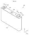
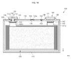
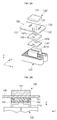
- FIGS. 1A , 1B , and 1C a perspective view, a sectional view, and an exploded perspective view of a secondary battery (100) according to some embodiments of the present invention are illustrated.
- FIGS. 2A and 2B a partially exploded perspective view and a side sectional view illustrating fuse parts (137) and peripheral structures of the secondary battery 100 illustrated in FIG. 1 are illustrated, and referring to FIG. 2C , a side sectional view illustrating a state after the fuse parts (137) are operated is illustrated.
- the secondary battery 100 includes a case 110, an electrode assembly 120, a cap plate 130, a first terminal 140 and a second terminal 150.
- the case 110 is made of a conductive metal, such as aluminum, an aluminum alloy, or nickel-plated steel, and may have a substantially hollow hexahedral shape having an opening through which the electrode assembly 120 may be accommodated. Although the opening is not illustrated in FIG. 1B , as the case 110 and the cap assembly 130 are in an assembled state, the upper portion of the cap assembly 130 substantially corresponds to the opening in the case 110.
- the interior surface of the case 110 is insulated, so that the case 110 is electrically insulated from the electrode assembly 120.
- the case 110 may also be called a can in some cases.
- the electrode assembly 120 may be formed by winding or laminating a stacked structure including a first electrode plate 121, a separator 122, and a second electrode plate 123.
- the first electrode plate 121 may be a positive electrode plate and the second electrode plate 123 may be a negative electrode plate, or vice versa.
- the first electrode plate 121 includes a first current collector 121 a formed of a metal foil or a metal mesh, such as aluminum or an aluminum alloy, a first coating portion 121 b formed by coating a first electrical active material, such as a transition metal oxide, on the first current collector 121 a, a first non-coating portion (first uncoated portion) 121c, on which the first electrical active material is not coated, and a first current collector tab 121 d extending from the first non-coating portion 121c to the outside (upward) to be electrically connected to the first terminal 140.
- the first current collector tab 121 d may function as a passage for current flowing between the first electrode plate 121 and the first terminal 140.
- the second electrode plate 123 includes a second current collector 123a formed of a metal foil or a metal mesh, such as copper, nickel, or a nickel alloy, a second coating portion 123b formed by coating a second electrical active material, such as graphite or carbon, on the second current collector 123a, a second non-coating portion (second uncoated portion) 123c, on which the second electrical active material is not coated, and a second current collector tab 123d extending from the second non-coating portion 123c to the outside (upward) to be electrically connected to the second terminal 150.
- the second current collector tab 123d may function as a passage for current flowing between the second electrode plate 123 and the second terminal 150.
- the separator 122 may be positioned between the first electrode plate 121 and the second electrode plate 123 to prevent or reduce instances of short circuiting and to allow for the movement of lithium ions.
- the separator 122 may be formed of polyethylene, polypropylene, or a combined film of polypropylene and polyethylene.
- the present invention does not limit the material of the separator 122 to those disclosed herein. Rather, the separator 122 may include any suitable separator material.
- a winding axis of the electrode assembly 120 is substantially parallel to terminal axes of the first and second terminals 140 and 150.
- the winding axis of the electrode assembly 120 and the terminal axes of the first and second terminals 140 and 150 are extending along the z direction in FIGS. 1B and 1C .
- the winding axis and the terminal axes are referred to as being substantially parallel to each other, it will be understood that the winding axis and the terminal axes may not meet each other even if they are stretched long or may meet each other when they are stretched very long.
- the first current collector tab 121 d is arranged or positioned between the electrode assembly 120 and the first terminal 140
- the second current collector tab 123d is arranged or positioned between the electrode assembly 120 and the second terminal 150. That is to say, the first current collector tab 121 d extends from a top end of the electrode assembly 120 toward the first terminal 140 to then be connected or welded to the first terminal 140.
- the second current collector tab 123d extends from the top end of the electrode assembly 120 toward the second terminal 150 to then be connected or welded to the second terminal 150.
- the first current collector tab 121d may correspond to the first non-coating portion 121 c of the first electrode plate 121, on which the first electrical active material is not coated, as described above, or a separate member connected to the first non-coating portion 121 c.
- the separate member may be made of one selected from the group consisting of aluminum, an aluminum alloy, nickel, a nickel alloy, copper, a copper alloy and equivalents thereof.
- the second current collector tab 123d may correspond to the second non-coating portion 123c of the second electrode plate 123, on which the second electrical active material is not coated, or a separate member connected to the second non-coating portion 123c.
- the separate member may be made of one selected from the group consisting of nickel, a nickel alloy, copper, a copper alloy, aluminum, an aluminum alloy, and equivalents thereof.
- a direction in which an electrolyte is injected is also parallel to the winding axis of the electrode assembly 120. Accordingly, when the electrolyte is injected, the electrode assembly 120 exhibits good electrolyte impregnating performance. In addition, during overcharge, internal gases of the electrode assembly 120 rapidly move to a safety vent 136, so that the safety vent 136 can be rapidly operated.
- first and second current collector tabs 121d and 123d (non-coating portions or separate members) of the electrode assembly 120 are directly electrically connected to the first and second terminals 140 and 150, shortening electrical paths, thereby reducing internal resistance of the secondary battery 100 and the number of components of the secondary battery 100.
- the electrode assembly 120 and electrolyte are accommodated within the case 110.
- the electrolyte may include an organic solvent, e.g., ethylene carbonate (EC), propylene carbonate (PC), diethyl carbonate (DEC), ethyl methyl carbonate (EMC), or dimethyl carbonate (DMC), and a lithium salt, e.g., LiPF 6 or LiBF 4 .
- the electrolyte may be a liquid, a solid, or a gel.
- the cap plate 130 has a substantially rectangular shape with a length (e.g., a length of a long side portion 131) and a width (e.g., a width of a short side portion 132) and is coupled to the case 110. That is to say, the cap plate 130 seals the opening of the case 110 and may be made of the same material as the case 110. For example, cap plate 130 may be coupled to the case 110 by laser and/or ultrasonic welding. In some cases, the cap plate 130 may also be called a cap assembly.
- the cap plate 130 includes a plug 134 closing an electrolyte injection hole 133 and a safety vent 136 closing a vent hole 135.
- the safety vent 136 may further include a notch 136a configured to be easily opened at a preset pressure.
- the cap plate 130 further includes a fuse part 137 electrically connected to the first current collector tab 121 d of the electrode assembly 120 and a terminal fixing part 138 constraining the first terminal 140. That is to say, the cap plate 130 includes at least one fuse part 137 (for example, two fuse parts as illustrated in FIGS. 1A , 1C , 2A and 2C ) downwardly extending and protruding a predetermined length from the cap plate 130, and at least one terminal fixing part 138 (for example, two terminal fixing parts as illustrated in FIGS. 1A , 1C and 2A ) upwardly extending and protruding a predetermined length from the cap plate 130.
- the fuse part 137 for example, two fuse parts as illustrated in FIGS. 1A , 1C , 2A and 2C
- terminal fixing part 138 for example, two terminal fixing parts as illustrated in FIGS. 1A , 1C and 2A
- the fuse part 137 comprises two fuse parts formed at opposite sides facing each other in a widthwise direction of the cap plate 130 (e.g., along the y-y direction), respectively
- the terminal fixing part 138 comprises two terminal fixing parts formed at opposite sides facing each other in a lengthwise direction of the cap plate 130 (e.g., along the x-x direction), respectively.
- the fuse part 137 and the terminal fixing part 138 of the cap plate 130 will be further described below.
- the first terminal 140 includes a first terminal plate 141 positioned on a top surface of the cap plate 130, a first insulation plate 142 positioned on a bottom surface of the cap plate 130, and a first current collector plate 143 positioned on a bottom surface of the first insulation plate 142.
- the first terminal plate 141 may be formed to be solid without a cavity inside and may have a substantially hexahedral shape.
- the first terminal plate 141 may be fixed to the top surface of the cap plate 130 through the terminal fixing part 138.
- the terminal fixing part 138 for example, formed at opposite sides of the first terminal plate 141 in the lengthwise direction of the cap plate 130 (e.g., along the x-x direction of the cap plate 130), may constrain left and right side surfaces of the first terminal plate 141.
- the terminal fixing part 138 is laser-welded or ultrasonically welded to the first terminal plate 141, thereby fixedly coupling the terminal fixing part 138 and the first terminal plate 141 to each other.
- the first insulation plate 142 may have a substantially hexahedral shape and may be coupled to the fuse part 137 downwardly extending and/or protruding from the bottom surface of the cap plate 130.
- a fuse throughhole 142a is formed in the first insulation plate 142. That is to say, each the fuse part 137 is attached to the cap plate 130 extending in the lengthwise direction of the cap plate 130 (e.g., along the x-x direction), the fuse throughhole 142a located to correspond to the fuse part 137 is formed in the first insulation plate 142, and the fuse part 137 is inserted in the fuse throughhole 142a.
- a fuse penetrating cutting groove instead of the fuse throughhole 142a, may be formed.
- the first current collector plate 143 may have a substantially hexahedral shape and may be coupled to the fuse parts 137.
- a fuse throughhole 143a is formed in the first current collector plate 143. That is to say, the fuse throughhole 143a is formed extendinmg along the lengthwise direction of the cap plate 130 (e.g., along the x-x direction).
- the fuse part 137 is fixed to the first current collector plate 143 by welding, coking or riveting, in a state in which it is coupled to the fuse throughhole 143a of the first current collector plate 143.
- a fuse penetrating cutting groove instead of the fuse throughhole 143a, may be formed.
- the first current collector tab 121 d extending from the electrode assembly 120 is connected to the first current collector plate 143. That is to say, the first current collector tab 121 d is laser-welded or ultrasonically welded to the first current collector plate 143.
- the first current collector plate 143 and the first current collector tab 121 d are both made of aluminum or an aluminum alloy, they can be easily electrically/mechanically connected to each other.
- the first current collector tab 121d of the electrode assembly 120, the cap plate 130 (including the case 110) and the first terminal 140 have the same polarity. That is to say, since the first current collector tab 121 d of the electrode assembly 120, the first current collector plate 143 of the first terminal 140, the fuse part 137 of the cap plate 130, the cap plate 130, and the first terminal plate 141 of the first terminal 140 are electrically connected to one another, they have the same polarity.
- the cap plate 130, the fuse part 137, the first current collector plate 143 and the first terminal plate 141 may also be made of aluminum or an aluminum alloy.
- the fuse part 137 may not be exposed to the outside, thereby preventing a flame or an arc from affecting exterior parts of the first insulation plate 142 when the fuse part 137 is melted/broken. Therefore, even when the fuse part 137 is melted/broken, the internal space of the secondary battery 100 is maintained at a stable state.
- the secondary battery 100 when the secondary battery 100 is overcharged, overcharge current is supplied to the electrode assembly 120 through the first terminal plate 141 of the first terminal 140, the cap plate 130, the fuse part 137 of the cap plate 130, the first current collector plate 143 and the first current collector tab 121 d. Accordingly, the fuse part 137 formed in the cap plate 130 is melted and broken, thereby securing the safety of the secondary battery 100.
- the fuse part 137 is directly formed on the cap plate 130, a fuse part configured to be limited to a separate current collector or tab may not need to be formed. That is to say, according to some embodiments of the present invention, because the fuse part 137 extending and protruding toward the electrode assembly 120 is directly formed on a bottom surface of the cap plate 130 to then be connected to the electrode assembly 120, an unlimited type of fuse part can be formed, unlike the conventional fuse part configured to be limited to a separate current collector or tab.
- the secondary battery 100 can easily control the thickness, width and length of the fuse part 137. That is to say, since the fuse part 137 is directly formed on the cap plate 130, the thickness, width and length of the fuse part 137 can be easily controlled to be suitable to the capacity or characteristic of the secondary battery 100.
- the secondary battery 100 can easily form a plurality of small-area fuse parts 137. That is to say, because the plurality of small-area fuse parts 137 extending from the cap plate 130 to the electrode assembly 120 are formed by casting or forging, the fuse parts 137 can firmly fix the electrode assembly 120 and can be operated in a secure manner.
- the second terminal 150 includes a second terminal plate 151 positioned on the top surface of the cap plate 130, a second insulation plate 152 positioned on the bottom surface of the cap plate 130, a second current collector plate 153 positioned on a bottom surface of the second insulation plate 152, and a current collector pillar 154 passing through the cap plate 130 from the second current collector plate 153 and fixed to the second terminal plate 151.
- the second terminal 150 includes an upper insulation plate 155 arranged or positioned between each of the second terminal plate 151 and the current collector pillar 154 and the cap plate 130.
- the second terminal 150 includes seal gaskets 156 arranged or positioned between the second current collector plate 153 and the cap plate 130 and between the current collector pillar 154 and the cap plate 130.
- the second current collector plate 153 and the second current collector pillar 154 are integrally formed, and the second current collector tab 123d is connected to the second current collector plate 153.
- the second current collector plate 153 and the second current collector pillar 154 are made of copper or a copper alloy. Accordingly, the second current collector tab 123d made of copper, a copper alloy, nickel or a nickel alloy is easily electrically/mechanically connected to the second current collector plate 153.
- the second terminal plate 151 is also positioned on the cap plate 130 and has a hole 151 a.
- the current collector pillar 154 is coupled and welded to the hole 151 a. For example, laser beams are applied to boundary regions of the upwardly exposed current collector pillar 154 and the second terminal plate 151, thereby melting the boundary regions to then be cooled and welded to each other.
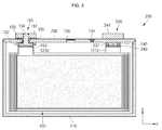
- FIG. 3 a sectional view of a secondary battery (200) according to another embodiment of the present invention is illustrated.
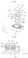
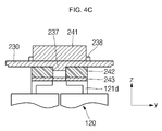
- FIGS. 4A and 4B a partially exploded perspective view and a side sectional view illustrating a fuse part (237) and peripheral structures thereof in the secondary battery (200) illustrated in FIG. 3 are illustrated, and referring to FIG. 4C , a side sectional view illustrating a state after the fuse part (237) is operated is illustrated.
- the secondary battery 200 includes a case 110, an electrode assembly 120, a cap plate 230, a first terminal 240, and a second terminal 150.
- the cap plate 230 includes a fuse part 237 electrically connected to the first current collector tab 121d of the electrode assembly 120 and a terminal fixing part 238 constraining the first terminal 240. That is to say, the cap plate 230 includes at least one fuse part 237 downwardly extending and protruding a predetermined length from the cap plate 230 and at least one terminal fixing part 238 upwardly extending and protruding a length (e.g., a predetermined length) from the cap plate 230.
- the fuse part 237 comprises two fuse parts formed at opposite sides facing each other in a lengthwise direction of the cap plate 230 (e.g., along the x-x direction), respectively, and the terminal fixing part 238 comprises two terminal fixing parts formed at opposite sides facing each other in a widthwise direction of the cap plate 230 (e.g., along the y-y direction), respectively.
- the fuse part 237 and the terminal fixing part 238 of the cap plate 230 will be further described below.
- the first terminal 240 includes a first terminal plate 241 positioned on a top surface of the cap plate 230, a first insulation plate 242 positioned on a bottom surface of the cap plate 230, and a first current collector plate 243 positioned on a bottom surface of the first insulation plate 242.
- the first terminal plate 241 may be formed to be solid without a cavity inside and may have a substantially hexahedral shape.
- the first terminal plate 241 may be fixed to the top surface of the cap plate 230 through the terminal fixing part 238.
- the terminal fixing parts 238, for example, formed at opposite sides of the first terminal plate 241 in the widthwise direction of the cap plate 230 (e.g., along the y-y direction of the cap plate 230), may constrain front and rear side surfaces of the first terminal plate 141.
- the terminal fixing part 238 is laser-welded or ultrasonically welded to the first terminal plate 241, thereby fixedly coupling the terminal fixing part 238 and the first terminal plate 241 to each other.
- the first insulation plate 242 may have a substantially hexahedral shape and may be coupled to the fuse part 237 downwardly extending and/or protruding from the bottom surface of the cap plate 230.
- a fuse throughhole 242a is formed in the first insulation plate 242. That is to say, each fuse part 237 is extending along the widthwise direction of the cap plate 230 (e.g., along the y-y direction), the fuse throughhole 242a located to correspond to the fuse parts 237 is formed in the first insulation plate 242, and the fuse part 237 is coupled to the fuse throughhole 242a.
- a fuse penetrating cutting groove instead of the fuse throughhole 242a, may be formed.
- the first current collector 243 may have a substantially hexahedral shape and may be coupled to the fuse parts 237.
- a fuse throughhole 243a is formed in the first current collector plate 243. That is to say, the fuse throughhole 243a is formed extending in the widthwise direction of the cap plate 230 (e.g., along the y-y direction).
- the fuse part 237 is fixed to the first current collector plate 243 by welding, coking or riveting, in a state in which it is coupled to the fuse throughhole 243a of the first current collector plate 243.
- a fuse penetrating cutting groove instead of the fuse throughhole 243a, may be formed.
- the first current collector tab 121 d extending from the electrode assembly 120 is connected to the first current collector plate 143. That is to say, the first current collector tab 121 d is laser-welded or ultrasonically welded to the first current collector plate 243.
- the first current collector tab 121d of the electrode assembly 120, the cap plate 230 (including the case 110) and the first terminal 240 have the same polarity. That is to say, because the first current collector tab 121 d of the electrode assembly 120, the first current collector plate 243 of the first terminal 240, the fuse part 237 of the cap plate 230, the cap plate 230, and the first terminal plate 241 of the first terminal 240 are electrically connected to one another, they have the same polarity.
- the fuse part 237 may not be mostly exposed to the outside, thereby preventing a flame or an arc from affecting exterior parts of the first insulation plate 242 when the fuse part 237 is melted/broken. Therefore, even when the fuse part 237 is melted/broken, the internal space of the secondary battery 200 is maintained at a stable state.
- the secondary battery 200 when the secondary battery 200 is overcharged, overcharge current is supplied to the electrode assembly 120 through the first terminal plate 241 of the first terminal 240, the cap plate 230, the fuse part 237 of the cap plate 230, the first current collector plate 243 and the first current collector tab 121 d. Accordingly, the fuse part 237 formed in the cap plate 230 is melted and broken, thereby securing the safety of the secondary battery 200.
- the fuse parts 137 and 237 may be formed in the lengthwise direction and in the widthwise direction of the cap plates 130 and 230, and the terminal fixing parts 138 and 238 may also be formed in the lengthwise direction and in the widthwise direction of the cap plates 130 and 230, respectively. Accordingly, the fuse throughholes 142a & 242a and143a & 243a, formed on the first insulation plates 142 and 242 and the first current collector plates 143 and 243, respectively, may be positioned to correspond to the fuse parts 137 and 237, respectively.
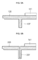
- FIGS. 5A and 5B are sectional views illustrating fuse parts of a secondary battery according to some embodiments of the present invention.
- a fuse part 137 may downwardly extend and protrude from a cap plate 130 and may be formed to be solid without a cavity inside.
- a fuse part 337 may downwardly extend and protrude from a cap plate 330 and may be formed to be hollow with a cavity inside.
- the solid fuse part 137 may be formed by performing one of casting, forging and an equivalent thereof, on the cap plate 130.
- the hollow fuse part 337 may be formed by performing one of casting and an equivalent thereof on the cap plate 330.
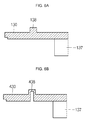
- FIGS. 6A and 6B sectional views illustrating terminal fixing parts of a secondary battery according to still another embodiment of the present invention are illustrated.
- a terminal fixing part 138 may upwardly extend and protrude from a cap plate 130 and may be formed to be solid without a cavity inside.
- a terminal fixing part 438 may upwardly extend and protrude from a cap plate 430 and may be formed to be hollow with a cavity inside.
- the solid terminal fixing part 138 may be formed by performing one of casting, forging and an equivalent thereof, on the cap plate 130.
- the hollow terminal fixing part 438 may be formed by performing one of casting and an equivalent thereof on the cap plate 430.
- FIG. 7 a perspective view illustrating an example of a battery module using a secondary battery according to still another embodiment of the present invention is illustrated.
- a plurality of secondary batteries 100 are arranged in a line, and a plurality of bus bars 510 are coupled to the arranged secondary batteries 100, thereby completing one battery module 1000.
- a first terminal 140 of one of the secondary batteries 100 and a second terminal 150 of another of the secondary batteries 100, adjacent to the one secondary battery 100 are welded through the bus bars 510, thereby provi8ding the battery module 1000 including the plurality of secondary batteries 100 connected to one another in series.
- the bus bars 510 may be made of aluminum or an aluminum alloy.
- the first terminal plate 141 of the first terminal 140 and the second terminal plate 151 of the second terminal 150 are also made of aluminum or an aluminum alloy, thereby easily welding the bus bars 510 to the first terminal 140 and the second terminal 150.
Landscapes
- Chemical & Material Sciences (AREA)
- Chemical Kinetics & Catalysis (AREA)
- Electrochemistry (AREA)
- General Chemical & Material Sciences (AREA)
- Engineering & Computer Science (AREA)
- Manufacturing & Machinery (AREA)
- Microelectronics & Electronic Packaging (AREA)
- Connection Of Batteries Or Terminals (AREA)
- Nitrogen Condensed Heterocyclic Rings (AREA)
- Secondary Cells (AREA)
- Control Of Eletrric Generators (AREA)
Applications Claiming Priority (1)
| Application Number | Priority Date | Filing Date | Title |
|---|---|---|---|
| KR1020150100459A KR102425797B1 (ko) | 2015-07-15 | 2015-07-15 | 이차 전지 |
Publications (2)
| Publication Number | Publication Date |
|---|---|
| EP3128572A1 true EP3128572A1 (de) | 2017-02-08 |
| EP3128572B1 EP3128572B1 (de) | 2019-06-12 |
Family
ID=55697087
Family Applications (1)
| Application Number | Title | Priority Date | Filing Date |
|---|---|---|---|
| EP16163959.6A Active EP3128572B1 (de) | 2015-07-15 | 2016-04-06 | Wiederaufladbare sekundärbatterie |
Country Status (4)
| Country | Link |
|---|---|
| US (1) | US10050253B2 (de) |
| EP (1) | EP3128572B1 (de) |
| KR (1) | KR102425797B1 (de) |
| CN (1) | CN106356475B (de) |
Cited By (2)
| Publication number | Priority date | Publication date | Assignee | Title |
|---|---|---|---|---|
| EP3588618A4 (de) * | 2017-02-22 | 2020-12-02 | Samsung SDI Co., Ltd. | Sekundärbatterie mit symmetrischem mehrfachlaschen |
| EP4354641A1 (de) * | 2022-10-14 | 2024-04-17 | Toyota Jidosha Kabushiki Kaisha | Stromspeicherzelle und stromunterbrechungsverfahren für eine stromspeicherzelle |
Families Citing this family (10)
| Publication number | Priority date | Publication date | Assignee | Title |
|---|---|---|---|---|
| WO2018021372A1 (ja) * | 2016-07-29 | 2018-02-01 | 三洋電機株式会社 | 二次電池 |
| KR102890540B1 (ko) | 2017-02-22 | 2025-11-26 | 삼성에스디아이 주식회사 | 멀티탭 쇼트 억제 구조를 갖는 이차 전지 |
| KR102777678B1 (ko) * | 2017-02-22 | 2025-03-10 | 삼성에스디아이 주식회사 | 이차 전지 |
| CN110326133A (zh) * | 2017-02-27 | 2019-10-11 | 三洋电机株式会社 | 方形二次电池以及其制造方法 |
| JP6947575B2 (ja) * | 2017-07-31 | 2021-10-13 | 株式会社Gsユアサ | 蓄電素子の製造方法 |
| CN110783519B (zh) * | 2019-09-23 | 2022-03-18 | 江苏正力新能电池技术有限公司 | 一种防止电池外短路的连接结构及电池顶盖 |
| CN112234296B (zh) * | 2019-10-23 | 2022-04-08 | 蜂巢能源科技有限公司 | 电芯以及电池模组 |
| JP7304371B2 (ja) | 2021-01-13 | 2023-07-06 | プライムプラネットエナジー&ソリューションズ株式会社 | 端子部品および二次電池 |
| CN115548600B (zh) * | 2021-06-30 | 2023-11-03 | 宁德时代新能源科技股份有限公司 | 一种电池单体、电池及用电设备 |
| KR20260020668A (ko) * | 2024-08-05 | 2026-02-12 | 삼성에스디아이 주식회사 | 서브 플레이트 어셈블리 및 이를 포함하는 이차 전지 |
Citations (4)
| Publication number | Priority date | Publication date | Assignee | Title |
|---|---|---|---|---|
| EP2509149A1 (de) * | 2011-04-04 | 2012-10-10 | SB LiMotive Co., Ltd. | Sekundärbatterie |
| EP2757609A1 (de) * | 2013-01-16 | 2014-07-23 | Samsung SDI Co., Ltd. | Wiederaufladbare Batterie |
| EP2849263A1 (de) * | 2013-09-13 | 2015-03-18 | Samsung SDI Co., Ltd. | Wiederaufladbare Batterie |
| US20150118528A1 (en) * | 2013-10-24 | 2015-04-30 | Samsung Sdi Co., Ltd. | Rechargeable battery having fuse unit |
Family Cites Families (7)
| Publication number | Priority date | Publication date | Assignee | Title |
|---|---|---|---|---|
| US20040170887A1 (en) * | 2001-08-07 | 2004-09-02 | Kenjin Masumoto | Non-aqueous electrolytic secondary battery |
| KR101074780B1 (ko) | 2009-09-30 | 2011-10-19 | 삼성에스디아이 주식회사 | 캡 조립체, 캔, 및 이를 이용한 이차 전지 |
| KR101222267B1 (ko) * | 2010-12-09 | 2013-01-15 | 로베르트 보쉬 게엠베하 | 이차 전지 |
| US9537121B2 (en) * | 2011-03-18 | 2017-01-03 | Samsung Sdi Co., Ltd. | Secondary battery and secondary battery pack having a flexible collecting tab extending through a cap plate |
| JP6006134B2 (ja) | 2013-02-08 | 2016-10-12 | トヨタ自動車株式会社 | 接続部材 |
| KR101416520B1 (ko) | 2013-02-18 | 2014-07-09 | (주)영하이테크 | 벤트 구조를 갖는 2차 전지용 캡 플레이트 및 그의 제조방법 |
| US9660249B2 (en) * | 2013-10-01 | 2017-05-23 | Samsung Sdi Co., Ltd. | Rechargeable battery having a fuse |
-
2015
- 2015-07-15 KR KR1020150100459A patent/KR102425797B1/ko active Active
- 2015-12-15 US US14/970,369 patent/US10050253B2/en active Active
-
2016
- 2016-03-25 CN CN201610177184.8A patent/CN106356475B/zh active Active
- 2016-04-06 EP EP16163959.6A patent/EP3128572B1/de active Active
Patent Citations (4)
| Publication number | Priority date | Publication date | Assignee | Title |
|---|---|---|---|---|
| EP2509149A1 (de) * | 2011-04-04 | 2012-10-10 | SB LiMotive Co., Ltd. | Sekundärbatterie |
| EP2757609A1 (de) * | 2013-01-16 | 2014-07-23 | Samsung SDI Co., Ltd. | Wiederaufladbare Batterie |
| EP2849263A1 (de) * | 2013-09-13 | 2015-03-18 | Samsung SDI Co., Ltd. | Wiederaufladbare Batterie |
| US20150118528A1 (en) * | 2013-10-24 | 2015-04-30 | Samsung Sdi Co., Ltd. | Rechargeable battery having fuse unit |
Cited By (3)
| Publication number | Priority date | Publication date | Assignee | Title |
|---|---|---|---|---|
| EP3588618A4 (de) * | 2017-02-22 | 2020-12-02 | Samsung SDI Co., Ltd. | Sekundärbatterie mit symmetrischem mehrfachlaschen |
| US11063304B2 (en) | 2017-02-22 | 2021-07-13 | Samsung Sdi Co., Ltd. | Secondary battery having symmetric multi-tabs |
| EP4354641A1 (de) * | 2022-10-14 | 2024-04-17 | Toyota Jidosha Kabushiki Kaisha | Stromspeicherzelle und stromunterbrechungsverfahren für eine stromspeicherzelle |
Also Published As
| Publication number | Publication date |
|---|---|
| US20170018759A1 (en) | 2017-01-19 |
| KR20170009065A (ko) | 2017-01-25 |
| CN106356475B (zh) | 2021-03-19 |
| EP3128572B1 (de) | 2019-06-12 |
| US10050253B2 (en) | 2018-08-14 |
| CN106356475A (zh) | 2017-01-25 |
| KR102425797B1 (ko) | 2022-07-28 |
Similar Documents
| Publication | Publication Date | Title |
|---|---|---|
| EP3128572B1 (de) | Wiederaufladbare sekundärbatterie | |
| US11289782B2 (en) | Secondary battery | |
| US9472802B2 (en) | Secondary battery | |
| US9425453B2 (en) | Battery module | |
| US20160043368A1 (en) | Secondary battery and battery module including secondary battery | |
| US11387528B2 (en) | Secondary battery | |
| US20120225333A1 (en) | Secondary battery and battery pack including secondary battery | |
| EP2905828B1 (de) | Wiederaufladbare Batterie | |
| US10038172B2 (en) | Rechargeable battery | |
| US9570780B2 (en) | Rechargeable battery | |
| US9023517B2 (en) | Secondary battery | |
| US9818991B2 (en) | Secondary battery | |
| US10522813B2 (en) | Secondary battery | |
| US20150214536A1 (en) | Secondary battery | |
| US10211446B2 (en) | Rechargeable battery | |
| US9806324B2 (en) | Secondary battery | |
| US9722237B2 (en) | Secondary battery | |
| US10333130B2 (en) | Secondary battery and secondary battery module | |
| US9337468B2 (en) | Secondary battery | |
| US10930918B2 (en) | Secondary battery | |
| US10115957B2 (en) | Secondary battery |
Legal Events
| Date | Code | Title | Description |
|---|---|---|---|
| PUAI | Public reference made under article 153(3) epc to a published international application that has entered the european phase |
Free format text: ORIGINAL CODE: 0009012 |
|
| STAA | Information on the status of an ep patent application or granted ep patent |
Free format text: STATUS: THE APPLICATION HAS BEEN PUBLISHED |
|
| AK | Designated contracting states |
Kind code of ref document: A1 Designated state(s): AL AT BE BG CH CY CZ DE DK EE ES FI FR GB GR HR HU IE IS IT LI LT LU LV MC MK MT NL NO PL PT RO RS SE SI SK SM TR |
|
| AX | Request for extension of the european patent |
Extension state: BA ME |
|
| STAA | Information on the status of an ep patent application or granted ep patent |
Free format text: STATUS: REQUEST FOR EXAMINATION WAS MADE |
|
| 17P | Request for examination filed |
Effective date: 20170612 |
|
| RBV | Designated contracting states (corrected) |
Designated state(s): AL AT BE BG CH CY CZ DE DK EE ES FI FR GB GR HR HU IE IS IT LI LT LU LV MC MK MT NL NO PL PT RO RS SE SI SK SM TR |
|
| GRAP | Despatch of communication of intention to grant a patent |
Free format text: ORIGINAL CODE: EPIDOSNIGR1 |
|
| STAA | Information on the status of an ep patent application or granted ep patent |
Free format text: STATUS: GRANT OF PATENT IS INTENDED |
|
| RIC1 | Information provided on ipc code assigned before grant |
Ipc: H01M 2/34 20060101ALI20181010BHEP Ipc: H01M 2/04 20060101AFI20181010BHEP Ipc: H01M 2/30 20060101ALN20181010BHEP Ipc: H01M 10/04 20060101ALI20181010BHEP Ipc: H01M 2/26 20060101ALN20181010BHEP |
|
| RIC1 | Information provided on ipc code assigned before grant |
Ipc: H01M 2/30 20060101ALN20181015BHEP Ipc: H01M 10/04 20060101ALI20181015BHEP Ipc: H01M 2/34 20060101ALI20181015BHEP Ipc: H01M 2/26 20060101ALN20181015BHEP Ipc: H01M 2/04 20060101AFI20181015BHEP |
|
| INTG | Intention to grant announced |
Effective date: 20181105 |
|
| GRAS | Grant fee paid |
Free format text: ORIGINAL CODE: EPIDOSNIGR3 |
|
| GRAA | (expected) grant |
Free format text: ORIGINAL CODE: 0009210 |
|
| STAA | Information on the status of an ep patent application or granted ep patent |
Free format text: STATUS: THE PATENT HAS BEEN GRANTED |
|
| AK | Designated contracting states |
Kind code of ref document: B1 Designated state(s): AL AT BE BG CH CY CZ DE DK EE ES FI FR GB GR HR HU IE IS IT LI LT LU LV MC MK MT NL NO PL PT RO RS SE SI SK SM TR |
|
| REG | Reference to a national code |
Ref country code: GB Ref legal event code: FG4D |
|
| REG | Reference to a national code |
Ref country code: CH Ref legal event code: EP |
|
| REG | Reference to a national code |
Ref country code: AT Ref legal event code: REF Ref document number: 1143756 Country of ref document: AT Kind code of ref document: T Effective date: 20190615 |
|
| REG | Reference to a national code |
Ref country code: DE Ref legal event code: R096 Ref document number: 602016015012 Country of ref document: DE |
|
| REG | Reference to a national code |
Ref country code: IE Ref legal event code: FG4D |
|
| REG | Reference to a national code |
Ref country code: NL Ref legal event code: MP Effective date: 20190612 |
|
| REG | Reference to a national code |
Ref country code: LT Ref legal event code: MG4D |
|
| PG25 | Lapsed in a contracting state [announced via postgrant information from national office to epo] |
Ref country code: LT Free format text: LAPSE BECAUSE OF FAILURE TO SUBMIT A TRANSLATION OF THE DESCRIPTION OR TO PAY THE FEE WITHIN THE PRESCRIBED TIME-LIMIT Effective date: 20190612 Ref country code: FI Free format text: LAPSE BECAUSE OF FAILURE TO SUBMIT A TRANSLATION OF THE DESCRIPTION OR TO PAY THE FEE WITHIN THE PRESCRIBED TIME-LIMIT Effective date: 20190612 Ref country code: AL Free format text: LAPSE BECAUSE OF FAILURE TO SUBMIT A TRANSLATION OF THE DESCRIPTION OR TO PAY THE FEE WITHIN THE PRESCRIBED TIME-LIMIT Effective date: 20190612 Ref country code: SE Free format text: LAPSE BECAUSE OF FAILURE TO SUBMIT A TRANSLATION OF THE DESCRIPTION OR TO PAY THE FEE WITHIN THE PRESCRIBED TIME-LIMIT Effective date: 20190612 Ref country code: NO Free format text: LAPSE BECAUSE OF FAILURE TO SUBMIT A TRANSLATION OF THE DESCRIPTION OR TO PAY THE FEE WITHIN THE PRESCRIBED TIME-LIMIT Effective date: 20190912 Ref country code: HR Free format text: LAPSE BECAUSE OF FAILURE TO SUBMIT A TRANSLATION OF THE DESCRIPTION OR TO PAY THE FEE WITHIN THE PRESCRIBED TIME-LIMIT Effective date: 20190612 |
|
| PG25 | Lapsed in a contracting state [announced via postgrant information from national office to epo] |
Ref country code: GR Free format text: LAPSE BECAUSE OF FAILURE TO SUBMIT A TRANSLATION OF THE DESCRIPTION OR TO PAY THE FEE WITHIN THE PRESCRIBED TIME-LIMIT Effective date: 20190913 Ref country code: LV Free format text: LAPSE BECAUSE OF FAILURE TO SUBMIT A TRANSLATION OF THE DESCRIPTION OR TO PAY THE FEE WITHIN THE PRESCRIBED TIME-LIMIT Effective date: 20190612 Ref country code: RS Free format text: LAPSE BECAUSE OF FAILURE TO SUBMIT A TRANSLATION OF THE DESCRIPTION OR TO PAY THE FEE WITHIN THE PRESCRIBED TIME-LIMIT Effective date: 20190612 Ref country code: BG Free format text: LAPSE BECAUSE OF FAILURE TO SUBMIT A TRANSLATION OF THE DESCRIPTION OR TO PAY THE FEE WITHIN THE PRESCRIBED TIME-LIMIT Effective date: 20190912 |
|
| REG | Reference to a national code |
Ref country code: AT Ref legal event code: MK05 Ref document number: 1143756 Country of ref document: AT Kind code of ref document: T Effective date: 20190612 |
|
| PG25 | Lapsed in a contracting state [announced via postgrant information from national office to epo] |
Ref country code: EE Free format text: LAPSE BECAUSE OF FAILURE TO SUBMIT A TRANSLATION OF THE DESCRIPTION OR TO PAY THE FEE WITHIN THE PRESCRIBED TIME-LIMIT Effective date: 20190612 Ref country code: NL Free format text: LAPSE BECAUSE OF FAILURE TO SUBMIT A TRANSLATION OF THE DESCRIPTION OR TO PAY THE FEE WITHIN THE PRESCRIBED TIME-LIMIT Effective date: 20190612 Ref country code: AT Free format text: LAPSE BECAUSE OF FAILURE TO SUBMIT A TRANSLATION OF THE DESCRIPTION OR TO PAY THE FEE WITHIN THE PRESCRIBED TIME-LIMIT Effective date: 20190612 Ref country code: RO Free format text: LAPSE BECAUSE OF FAILURE TO SUBMIT A TRANSLATION OF THE DESCRIPTION OR TO PAY THE FEE WITHIN THE PRESCRIBED TIME-LIMIT Effective date: 20190612 Ref country code: CZ Free format text: LAPSE BECAUSE OF FAILURE TO SUBMIT A TRANSLATION OF THE DESCRIPTION OR TO PAY THE FEE WITHIN THE PRESCRIBED TIME-LIMIT Effective date: 20190612 Ref country code: PT Free format text: LAPSE BECAUSE OF FAILURE TO SUBMIT A TRANSLATION OF THE DESCRIPTION OR TO PAY THE FEE WITHIN THE PRESCRIBED TIME-LIMIT Effective date: 20191014 Ref country code: SK Free format text: LAPSE BECAUSE OF FAILURE TO SUBMIT A TRANSLATION OF THE DESCRIPTION OR TO PAY THE FEE WITHIN THE PRESCRIBED TIME-LIMIT Effective date: 20190612 |
|
| PG25 | Lapsed in a contracting state [announced via postgrant information from national office to epo] |
Ref country code: SM Free format text: LAPSE BECAUSE OF FAILURE TO SUBMIT A TRANSLATION OF THE DESCRIPTION OR TO PAY THE FEE WITHIN THE PRESCRIBED TIME-LIMIT Effective date: 20190612 Ref country code: IT Free format text: LAPSE BECAUSE OF FAILURE TO SUBMIT A TRANSLATION OF THE DESCRIPTION OR TO PAY THE FEE WITHIN THE PRESCRIBED TIME-LIMIT Effective date: 20190612 Ref country code: IS Free format text: LAPSE BECAUSE OF FAILURE TO SUBMIT A TRANSLATION OF THE DESCRIPTION OR TO PAY THE FEE WITHIN THE PRESCRIBED TIME-LIMIT Effective date: 20191012 Ref country code: ES Free format text: LAPSE BECAUSE OF FAILURE TO SUBMIT A TRANSLATION OF THE DESCRIPTION OR TO PAY THE FEE WITHIN THE PRESCRIBED TIME-LIMIT Effective date: 20190612 |
|
| REG | Reference to a national code |
Ref country code: DE Ref legal event code: R097 Ref document number: 602016015012 Country of ref document: DE |
|
| PG25 | Lapsed in a contracting state [announced via postgrant information from national office to epo] |
Ref country code: TR Free format text: LAPSE BECAUSE OF FAILURE TO SUBMIT A TRANSLATION OF THE DESCRIPTION OR TO PAY THE FEE WITHIN THE PRESCRIBED TIME-LIMIT Effective date: 20190612 |
|
| PLBE | No opposition filed within time limit |
Free format text: ORIGINAL CODE: 0009261 |
|
| STAA | Information on the status of an ep patent application or granted ep patent |
Free format text: STATUS: NO OPPOSITION FILED WITHIN TIME LIMIT |
|
| PG25 | Lapsed in a contracting state [announced via postgrant information from national office to epo] |
Ref country code: PL Free format text: LAPSE BECAUSE OF FAILURE TO SUBMIT A TRANSLATION OF THE DESCRIPTION OR TO PAY THE FEE WITHIN THE PRESCRIBED TIME-LIMIT Effective date: 20190612 Ref country code: DK Free format text: LAPSE BECAUSE OF FAILURE TO SUBMIT A TRANSLATION OF THE DESCRIPTION OR TO PAY THE FEE WITHIN THE PRESCRIBED TIME-LIMIT Effective date: 20190612 |
|
| 26N | No opposition filed |
Effective date: 20200313 |
|
| PG25 | Lapsed in a contracting state [announced via postgrant information from national office to epo] |
Ref country code: IS Free format text: LAPSE BECAUSE OF FAILURE TO SUBMIT A TRANSLATION OF THE DESCRIPTION OR TO PAY THE FEE WITHIN THE PRESCRIBED TIME-LIMIT Effective date: 20200224 Ref country code: SI Free format text: LAPSE BECAUSE OF FAILURE TO SUBMIT A TRANSLATION OF THE DESCRIPTION OR TO PAY THE FEE WITHIN THE PRESCRIBED TIME-LIMIT Effective date: 20190612 |
|
| PG2D | Information on lapse in contracting state deleted |
Ref country code: IS |
|
| REG | Reference to a national code |
Ref country code: DE Ref legal event code: R079 Ref document number: 602016015012 Country of ref document: DE Free format text: PREVIOUS MAIN CLASS: H01M0002040000 Ipc: H01M0050147000 |
|
| PG25 | Lapsed in a contracting state [announced via postgrant information from national office to epo] |
Ref country code: MC Free format text: LAPSE BECAUSE OF FAILURE TO SUBMIT A TRANSLATION OF THE DESCRIPTION OR TO PAY THE FEE WITHIN THE PRESCRIBED TIME-LIMIT Effective date: 20190612 |
|
| REG | Reference to a national code |
Ref country code: CH Ref legal event code: PL |
|
| PG25 | Lapsed in a contracting state [announced via postgrant information from national office to epo] |
Ref country code: LU Free format text: LAPSE BECAUSE OF NON-PAYMENT OF DUE FEES Effective date: 20200406 Ref country code: CH Free format text: LAPSE BECAUSE OF NON-PAYMENT OF DUE FEES Effective date: 20200430 Ref country code: LI Free format text: LAPSE BECAUSE OF NON-PAYMENT OF DUE FEES Effective date: 20200430 |
|
| REG | Reference to a national code |
Ref country code: BE Ref legal event code: MM Effective date: 20200430 |
|
| PG25 | Lapsed in a contracting state [announced via postgrant information from national office to epo] |
Ref country code: BE Free format text: LAPSE BECAUSE OF NON-PAYMENT OF DUE FEES Effective date: 20200430 |
|
| PG25 | Lapsed in a contracting state [announced via postgrant information from national office to epo] |
Ref country code: IE Free format text: LAPSE BECAUSE OF NON-PAYMENT OF DUE FEES Effective date: 20200406 |
|
| PG25 | Lapsed in a contracting state [announced via postgrant information from national office to epo] |
Ref country code: MT Free format text: LAPSE BECAUSE OF FAILURE TO SUBMIT A TRANSLATION OF THE DESCRIPTION OR TO PAY THE FEE WITHIN THE PRESCRIBED TIME-LIMIT Effective date: 20190612 Ref country code: CY Free format text: LAPSE BECAUSE OF FAILURE TO SUBMIT A TRANSLATION OF THE DESCRIPTION OR TO PAY THE FEE WITHIN THE PRESCRIBED TIME-LIMIT Effective date: 20190612 |
|
| PG25 | Lapsed in a contracting state [announced via postgrant information from national office to epo] |
Ref country code: MK Free format text: LAPSE BECAUSE OF FAILURE TO SUBMIT A TRANSLATION OF THE DESCRIPTION OR TO PAY THE FEE WITHIN THE PRESCRIBED TIME-LIMIT Effective date: 20190612 |
|
| P01 | Opt-out of the competence of the unified patent court (upc) registered |
Effective date: 20230528 |
|
| PGFP | Annual fee paid to national office [announced via postgrant information from national office to epo] |
Ref country code: DE Payment date: 20250408 Year of fee payment: 10 |
|
| PGFP | Annual fee paid to national office [announced via postgrant information from national office to epo] |
Ref country code: GB Payment date: 20250403 Year of fee payment: 10 |
|
| PGFP | Annual fee paid to national office [announced via postgrant information from national office to epo] |
Ref country code: FR Payment date: 20250409 Year of fee payment: 10 |