EP3128595A1 - Batterie rechargeable, bloc de batteries, dispositif électronique, véhicule électrique, dispositif de stockage d'électricité et système électrique - Google Patents
Batterie rechargeable, bloc de batteries, dispositif électronique, véhicule électrique, dispositif de stockage d'électricité et système électrique Download PDFInfo
- Publication number
- EP3128595A1 EP3128595A1 EP15773462.5A EP15773462A EP3128595A1 EP 3128595 A1 EP3128595 A1 EP 3128595A1 EP 15773462 A EP15773462 A EP 15773462A EP 3128595 A1 EP3128595 A1 EP 3128595A1
- Authority
- EP
- European Patent Office
- Prior art keywords
- negative electrode
- positive electrode
- secondary battery
- active material
- lithium
- Prior art date
- Legal status (The legal status is an assumption and is not a legal conclusion. Google has not performed a legal analysis and makes no representation as to the accuracy of the status listed.)
- Granted
Links
Images







Classifications
-
- H—ELECTRICITY
- H01—ELECTRIC ELEMENTS
- H01M—PROCESSES OR MEANS, e.g. BATTERIES, FOR THE DIRECT CONVERSION OF CHEMICAL ENERGY INTO ELECTRICAL ENERGY
- H01M4/00—Electrodes
- H01M4/02—Electrodes composed of, or comprising, active material
- H01M4/36—Selection of substances as active materials, active masses, active liquids
- H01M4/48—Selection of substances as active materials, active masses, active liquids of inorganic oxides or hydroxides
- H01M4/50—Selection of substances as active materials, active masses, active liquids of inorganic oxides or hydroxides of manganese
- H01M4/505—Selection of substances as active materials, active masses, active liquids of inorganic oxides or hydroxides of manganese of mixed oxides or hydroxides containing manganese for inserting or intercalating light metals, e.g. LiMn2O4 or LiMn2OxFy
-
- H—ELECTRICITY
- H01—ELECTRIC ELEMENTS
- H01M—PROCESSES OR MEANS, e.g. BATTERIES, FOR THE DIRECT CONVERSION OF CHEMICAL ENERGY INTO ELECTRICAL ENERGY
- H01M10/00—Secondary cells; Manufacture thereof
- H01M10/05—Accumulators with non-aqueous electrolyte
- H01M10/052—Li-accumulators
- H01M10/0525—Rocking-chair batteries, i.e. batteries with lithium insertion or intercalation in both electrodes; Lithium-ion batteries
-
- H—ELECTRICITY
- H01—ELECTRIC ELEMENTS
- H01M—PROCESSES OR MEANS, e.g. BATTERIES, FOR THE DIRECT CONVERSION OF CHEMICAL ENERGY INTO ELECTRICAL ENERGY
- H01M4/00—Electrodes
- H01M4/02—Electrodes composed of, or comprising, active material
- H01M4/13—Electrodes for accumulators with non-aqueous electrolyte, e.g. for lithium-accumulators; Processes of manufacture thereof
- H01M4/131—Electrodes based on mixed oxides or hydroxides, or on mixtures of oxides or hydroxides, e.g. LiCoOx
-
- H—ELECTRICITY
- H01—ELECTRIC ELEMENTS
- H01M—PROCESSES OR MEANS, e.g. BATTERIES, FOR THE DIRECT CONVERSION OF CHEMICAL ENERGY INTO ELECTRICAL ENERGY
- H01M4/00—Electrodes
- H01M4/02—Electrodes composed of, or comprising, active material
- H01M4/13—Electrodes for accumulators with non-aqueous electrolyte, e.g. for lithium-accumulators; Processes of manufacture thereof
- H01M4/136—Electrodes based on inorganic compounds other than oxides or hydroxides, e.g. sulfides, selenides, tellurides, halogenides or LiCoFy
-
- H—ELECTRICITY
- H01—ELECTRIC ELEMENTS
- H01M—PROCESSES OR MEANS, e.g. BATTERIES, FOR THE DIRECT CONVERSION OF CHEMICAL ENERGY INTO ELECTRICAL ENERGY
- H01M4/00—Electrodes
- H01M4/02—Electrodes composed of, or comprising, active material
- H01M4/36—Selection of substances as active materials, active masses, active liquids
- H01M4/48—Selection of substances as active materials, active masses, active liquids of inorganic oxides or hydroxides
- H01M4/485—Selection of substances as active materials, active masses, active liquids of inorganic oxides or hydroxides of mixed oxides or hydroxides for inserting or intercalating light metals, e.g. LiTi2O4 or LiTi2OxFy
-
- H—ELECTRICITY
- H01—ELECTRIC ELEMENTS
- H01M—PROCESSES OR MEANS, e.g. BATTERIES, FOR THE DIRECT CONVERSION OF CHEMICAL ENERGY INTO ELECTRICAL ENERGY
- H01M4/00—Electrodes
- H01M4/02—Electrodes composed of, or comprising, active material
- H01M4/36—Selection of substances as active materials, active masses, active liquids
- H01M4/58—Selection of substances as active materials, active masses, active liquids of inorganic compounds other than oxides or hydroxides, e.g. sulfides, selenides, tellurides, halogenides or LiCoFy; of polyanionic structures, e.g. phosphates, silicates or borates
- H01M4/5825—Oxygenated metallic salts or polyanionic structures, e.g. borates, phosphates, silicates, olivines
-
- H—ELECTRICITY
- H01—ELECTRIC ELEMENTS
- H01M—PROCESSES OR MEANS, e.g. BATTERIES, FOR THE DIRECT CONVERSION OF CHEMICAL ENERGY INTO ELECTRICAL ENERGY
- H01M10/00—Secondary cells; Manufacture thereof
- H01M10/05—Accumulators with non-aqueous electrolyte
- H01M10/058—Construction or manufacture
- H01M10/0585—Construction or manufacture of accumulators having only flat construction elements, i.e. flat positive electrodes, flat negative electrodes and flat separators
-
- H—ELECTRICITY
- H01—ELECTRIC ELEMENTS
- H01M—PROCESSES OR MEANS, e.g. BATTERIES, FOR THE DIRECT CONVERSION OF CHEMICAL ENERGY INTO ELECTRICAL ENERGY
- H01M10/00—Secondary cells; Manufacture thereof
- H01M10/05—Accumulators with non-aqueous electrolyte
- H01M10/058—Construction or manufacture
- H01M10/0587—Construction or manufacture of accumulators having only wound construction elements, i.e. wound positive electrodes, wound negative electrodes and wound separators
-
- H—ELECTRICITY
- H01—ELECTRIC ELEMENTS
- H01M—PROCESSES OR MEANS, e.g. BATTERIES, FOR THE DIRECT CONVERSION OF CHEMICAL ENERGY INTO ELECTRICAL ENERGY
- H01M4/00—Electrodes
- H01M4/02—Electrodes composed of, or comprising, active material
- H01M2004/021—Physical characteristics, e.g. porosity, surface area
-
- H—ELECTRICITY
- H01—ELECTRIC ELEMENTS
- H01M—PROCESSES OR MEANS, e.g. BATTERIES, FOR THE DIRECT CONVERSION OF CHEMICAL ENERGY INTO ELECTRICAL ENERGY
- H01M10/00—Secondary cells; Manufacture thereof
- H01M10/42—Methods or arrangements for servicing or maintenance of secondary cells or secondary half-cells
- H01M2010/4292—Aspects relating to capacity ratio of electrodes/electrolyte or anode/cathode
-
- H—ELECTRICITY
- H01—ELECTRIC ELEMENTS
- H01M—PROCESSES OR MEANS, e.g. BATTERIES, FOR THE DIRECT CONVERSION OF CHEMICAL ENERGY INTO ELECTRICAL ENERGY
- H01M2220/00—Batteries for particular applications
- H01M2220/20—Batteries in motive systems, e.g. vehicle, ship, plane
-
- Y—GENERAL TAGGING OF NEW TECHNOLOGICAL DEVELOPMENTS; GENERAL TAGGING OF CROSS-SECTIONAL TECHNOLOGIES SPANNING OVER SEVERAL SECTIONS OF THE IPC; TECHNICAL SUBJECTS COVERED BY FORMER USPC CROSS-REFERENCE ART COLLECTIONS [XRACs] AND DIGESTS
- Y02—TECHNOLOGIES OR APPLICATIONS FOR MITIGATION OR ADAPTATION AGAINST CLIMATE CHANGE
- Y02E—REDUCTION OF GREENHOUSE GAS [GHG] EMISSIONS, RELATED TO ENERGY GENERATION, TRANSMISSION OR DISTRIBUTION
- Y02E60/00—Enabling technologies; Technologies with a potential or indirect contribution to GHG emissions mitigation
- Y02E60/10—Energy storage using batteries
-
- Y—GENERAL TAGGING OF NEW TECHNOLOGICAL DEVELOPMENTS; GENERAL TAGGING OF CROSS-SECTIONAL TECHNOLOGIES SPANNING OVER SEVERAL SECTIONS OF THE IPC; TECHNICAL SUBJECTS COVERED BY FORMER USPC CROSS-REFERENCE ART COLLECTIONS [XRACs] AND DIGESTS
- Y02—TECHNOLOGIES OR APPLICATIONS FOR MITIGATION OR ADAPTATION AGAINST CLIMATE CHANGE
- Y02P—CLIMATE CHANGE MITIGATION TECHNOLOGIES IN THE PRODUCTION OR PROCESSING OF GOODS
- Y02P70/00—Climate change mitigation technologies in the production process for final industrial or consumer products
- Y02P70/50—Manufacturing or production processes characterised by the final manufactured product
-
- Y—GENERAL TAGGING OF NEW TECHNOLOGICAL DEVELOPMENTS; GENERAL TAGGING OF CROSS-SECTIONAL TECHNOLOGIES SPANNING OVER SEVERAL SECTIONS OF THE IPC; TECHNICAL SUBJECTS COVERED BY FORMER USPC CROSS-REFERENCE ART COLLECTIONS [XRACs] AND DIGESTS
- Y02—TECHNOLOGIES OR APPLICATIONS FOR MITIGATION OR ADAPTATION AGAINST CLIMATE CHANGE
- Y02T—CLIMATE CHANGE MITIGATION TECHNOLOGIES RELATED TO TRANSPORTATION
- Y02T10/00—Road transport of goods or passengers
- Y02T10/60—Other road transportation technologies with climate change mitigation effect
- Y02T10/70—Energy storage systems for electromobility, e.g. batteries
Definitions
- Patent Documents 1 to 6 below disclose technologies related to the secondary batteries.
- Patent Document 2 Japanese Patent Application Laid-Open No. 2011-113961 ) describes making the area of the positive electrode larger than the area of the negative electrode. However, Patent Document 2 is silent about defining both of the electrode areas and the capacity balance.
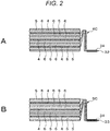
- the positive electrode current collector exposed portions 4C integrally extend from the positive electrode current collector 4A.
- the positive electrode current collector exposed portions 4C formed of a plurality of layers are bent to have an approximately U shape in cross-section, and the tip portions are connected with the positive electrode tub 32 by the method such as ultrasonic welding or resistance welding.
- a positive electrode active material in which a curve that indicates change of a potential with respect to a capacity (V vs. Li/Li + ) has at least a plateau region where the potential is approximately constant and a potential rising region where the potential drastically rises and changes in a charge end stage is used.
- V vs. Li/Li + a positive electrode active material in which a curve that indicates change of a potential with respect to a capacity
- a positive electrode active material at least either a lithium iron phosphate compound having an olivine structure or lithium-manganese composite oxide having a spinel structure can be used.
- An example of the lithium-manganese composite oxide having a spinel structure includes a lithium composite oxide expressed by a (Chemical Formula 2): (Chemical Formula 2) Li v Mn (2-w) M2 w O s (in the formula, M2 expresses at least one type of a group composed of cobalt (Co), nickel (Ni), magnesium (Mg), aluminum (Al), boron (B), titanium (Ti), vanadium (V), chromium (Cr), iron (Fe), copper (Cu), zinc (Zn), molybdenum (Mo), tin (Sn), calcium (Ca), strontium (Sr), and tungsten (W).
- a (Chemical Formula 2) Li v Mn (2-w) M2 w O s
- M2 expresses at least one type of a group composed of cobalt (Co), nickel (Ni), magnesium (Mg), aluminum (Al), boron (B), titanium (Ti), vanadium (V),
- v, w, and s are values in ranges of 0.9 ⁇ v ⁇ 1.1, 0 ⁇ w ⁇ 0.6, and 3.7 ⁇ s ⁇ 4.1. Note that a composition of lithium differs depending on a state of charge and discharge, and the value of v expresses a value in a fully discharged state).
- the formula (C) is satisfied, and thus the discharge termination is not defined only by the drastic voltage change in the discharge end stage of one electrode, and the voltage change in the discharge end stage is shared by both electrodes. Therefore, an overdischarge state of the electrodes is suppressed, and deterioration of the characteristics can be suppressed. Further, a discharge cut-off voltage can be decreased. Therefore, an output can be improved. For example, in a case where the cut-off voltage at the time of discharge is set to 1.0V, the difference between the potential of the positive electrode and the potential of the negative electrode becomes 1.0 V.
- the discharge termination is defined by drastic potential change in the discharge end stage of only the negative electrode, and the potential of the negative electrode rises in the discharge end stage and the negative electrode is in an extreme overdischarge state. Further, a side reaction may be caused on the negative electrode, and the negative electrode may be deteriorated. As illustrated in Fig. 5C , the discharge termination is defined by the drastic potential change in the discharge end stage of only the positive electrode, and the potential of the positive electrode falls in the discharge end stage and the positive electrode is in an extreme overdischarge state. Further, a side reaction may be caused, and the positive electrode may be deteriorated.
- the above-described secondary battery can be manufactured by following processes, for example.
- the secondary battery according to the third embodiment satisfies formulas (A) to (C), similarly to the first embodiment, and thus has similar effect to the secondary battery according to the first embodiment.
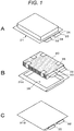
- the positive electrode 54 and the negative electrode 55 on which the electrolyte layer 57 has been formed are laminated through the separator 56, and a laminated body is obtained.
- the laminated body is wound in a longitudinal direction.
- the protective tape 58 is glued on an outermost peripheral portion, and the wound electrode body 50 is formed.
- the wound electrode body 50 is sandwiched by the packaging materials 60, and an outer peripheral edge portion except one side is thermally fused and formed into a bag, and the wound electrode body 50 is housed inside the packaging materials 60.
- the adhesive film 61 is inserted between the positive electrode lead 52 and the negative electrode lead 53, and the packaging materials 60.
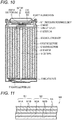
- the negative electrode 92 has a structure in which a negative electrode active material layer 92B is provided on both surfaces of a negative electrode current collector 92A, for example. Note that, although not illustrated, the negative electrode 92 may have a region where the negative electrode active material layer 92B is provided only on one surface of the negative electrode current collector 92A.
- the negative electrode current collector 92A is configured from metal foil such as copper foil or aluminum foil.
- the simplified battery pack includes a battery cell 101, tubs 102a and 102b pulled out of the battery cell 101, insulating tapes 103a to 103c, an insulating plate 104, a circuit board 105 in which a protection circuit (protection circuit module (PCM)) is formed, and a connector 106.
- the battery cell 101 is similar to any of the secondary batteries of the first to third embodiments, for example.
- the connector 106 for an output is connected to the circuit board 105.
- Members of the battery cell 101, the insulating plate 104, and the circuit board 105 are fixed with the insulating tapes 103a to 103c stuck on predetermined places.
- Fig. 14 is a block diagram illustrating a circuit configuration example of a case where the secondary batteries according to the first to fourth embodiments of the present technology are applied to a battery pack.
- the battery pack includes an assembled battery 301, a package, a switch unit 304 including a charge control switch 302a and a discharge control switch 303a, a current detection resistance 307, a temperature detection element 308, and a control unit 310.
- the assembled battery 301 is formed such that a plurality of secondary batteries 301a is connected in series and/or in parallel.
- the secondary battery 301a at least any of the secondary batteries of the first to fourth embodiments of the present technology can be used.
- Fig. 14 illustrates a case where six secondary batteries 301a are connected in an arrangement of two cells in parallel and three cells in series (2P3S) as an example.
- any connection method such as n cells in parallel and m cells in series (n and m are integers), may be employed.
- the switch unit 304 includes the charge control switch 302a and a diode 302b, and the discharge control switch 303a and a diode 303b, and is controlled by the control unit 310.
- the diode 302b has a polarity in an opposite direction to a charge current flowing in a direction from the positive electrode terminal 321 to the assembled battery 301, and in a forward direction with respect to a discharge current flowing in a direction from the negative electrode lead 322 to the assembled battery 301.
- the diode 303b has a polarity in a forward direction with respect to the charge current and in an opposite direction to the discharge current. Note that, in the example, the switch unit 304 is provided at the + side. However, the switch unit 304 may be provided at the - side.
- the discharge control switch 303a is controlled by the control unit 310 to be turned OFF when the battery voltage becomes an overdischarge detection voltage so that a discharge current does not flow in the current path of the assembled battery 301. After the discharge control switch 303a is turned OFF, only charge is available through the diode 303b. Further, the discharge control switch 303a is controlled by the control unit 310 to be turned OFF when a large current flows at the time of discharge, and to interrupt the discharge current flowing in the current path of the assembled battery 301.
- a charge and discharge switch a semiconductor switch of MOSFET or the like can be used.
- a parasitic diode of the MOSFET functions as the diodes 302b and 303b.
- the switch control unit 314 supplies control signals DO and CO to respective gates of the charge control switch 302a and the discharge control switch 303a.
- the charge control switch 302a and the discharge control switch 303a are turned ON by a gate potential that is lower than a source potential by a predetermined value or more. That is, in normal charge and discharge operations, the control signals CO and DO are set to a low level, and the charge control switch 302a and the discharge control switch 303a are turned to be an ON state.
- the control signals CO and DO are set to a high level, the charge control switch 302a and the discharge control switch 303a are turned to be an OFF state.
- At least any of the secondary batteries according to the first to fourth embodiments and the battery packs according to the fifth and sixth embodiments of the present technology can be used to be mounted on a device such as an electronic device, an electrically driven vehicle, or a storage device, or to supply power.
- Examples of the storage device include power storage source for building such as houses or for power generation facilities.
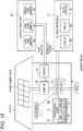
- the house 401 is provided with a power generation device 404, power consuming devices 405, the storage device 403, a control device 410 that controls the devices, the smart meter 407, and sensors 411 that acquire various types of information.
- the devices are connected through the power network 409 and the information network 412.
- a solar battery or a fuel battery is used, and the generated power is supplied to the power consuming device 405 and/or the storage device 403.
- the power consuming devices 405 are a refrigerator 405a, an air conditioner 405b as a space conditioning device, a television 405c as a television receiver, a bath 405d, and the like.
- the power consuming devices 405 include electrically driven vehicles 406.
- the electrically driven vehicles 406 are an electric car 406a, a hybrid car 406b, and an electric motorcycle 406c.
- the secondary battery of the present technology is applied to the storage device 403.
- the secondary battery of the present technology may be configured from the above-described lithium ion secondary battery, for example.
- the smart meter 407 includes a function to measure a used amount of commercial power, and to transmit the measured used amount to a power company.
- the power network 409 may be one of or a combination of DC power distribution, AC power distribution, and non-contact power distribution.
- the control device 410 that controls the units is configured from a central processing unit (CPU), a random access memory (RAM), a read only memory (ROM), and the like.
- the control device 410 is stored in the storage device 403.
- the control device 410 is connected with the storage device 403, the domestic power generation device 404, the power consuming devices 405, the various sensors 411, and the server 413 through the information network 412, and has a function to adjust the used amount of the commercial power and the power generation amount.
- the control device 410 may have a function to perform power transaction in a power market.
- Fig. 16 schematically illustrates an example of a configuration of a hybrid vehicle that employs a series hybrid system to which the present technology is applied.
- the series hybrid system is a car that travels by a power driving force conversion device using power generated by a generator moved by an engine or power stored in a battery once.
- an engine 501 In this hybrid vehicle 500, an engine 501, a generator 502, a power driving force conversion device 503, a drive wheel 504a, a drive wheel 504b, a wheel 505a, a wheel 505b, a battery 508, a vehicle control device 509, various sensors 510, and a charging port 511 are mounted.
- the above-described secondary battery of the present technology is applied to the battery 508.
- Example 1-1 an electrolyte solution similar to that of Example 1-1 was poured, and the remaining one side was thermally fused and sealed under decompression. At this time, the matrix high molecular compound layer was impregnated with the electrolyte solution, and PVdF as the matrix high molecular compound layer swelled and a gel electrolyte (gel electrolyte layer) was formed. The intended secondary battery was obtained.
Landscapes
- Chemical & Material Sciences (AREA)
- Chemical Kinetics & Catalysis (AREA)
- Electrochemistry (AREA)
- General Chemical & Material Sciences (AREA)
- Engineering & Computer Science (AREA)
- Inorganic Chemistry (AREA)
- Materials Engineering (AREA)
- Crystallography & Structural Chemistry (AREA)
- Manufacturing & Machinery (AREA)
- Secondary Cells (AREA)
- Battery Electrode And Active Subsutance (AREA)
- Sealing Battery Cases Or Jackets (AREA)
Applications Claiming Priority (2)
| Application Number | Priority Date | Filing Date | Title |
|---|---|---|---|
| JP2014077107 | 2014-04-03 | ||
| PCT/JP2015/000423 WO2015151376A1 (fr) | 2014-04-03 | 2015-01-30 | Batterie rechargeable, bloc de batteries, dispositif électronique, véhicule électrique, dispositif de stockage d'électricité et système électrique |
Publications (3)
| Publication Number | Publication Date |
|---|---|
| EP3128595A1 true EP3128595A1 (fr) | 2017-02-08 |
| EP3128595A4 EP3128595A4 (fr) | 2017-10-11 |
| EP3128595B1 EP3128595B1 (fr) | 2019-10-23 |
Family
ID=54239732
Family Applications (1)
| Application Number | Title | Priority Date | Filing Date |
|---|---|---|---|
| EP15773462.5A Active EP3128595B1 (fr) | 2014-04-03 | 2015-01-30 | Batterie rechargeable, bloc de batteries, dispositif électronique, véhicule électrique, dispositif de stockage d'électricité et système électrique |
Country Status (6)
| Country | Link |
|---|---|
| US (1) | US20170110725A1 (fr) |
| EP (1) | EP3128595B1 (fr) |
| JP (1) | JP6597599B2 (fr) |
| CN (1) | CN106133980B (fr) |
| CA (1) | CA2941316C (fr) |
| WO (1) | WO2015151376A1 (fr) |
Cited By (2)
| Publication number | Priority date | Publication date | Assignee | Title |
|---|---|---|---|---|
| WO2021125873A1 (fr) * | 2019-12-20 | 2021-06-24 | 주식회사 엘지에너지솔루션 | Électrode positive pour batterie secondaire au lithium et batterie secondaire au lithium la comprenant |
| EP3955339A1 (fr) * | 2020-08-11 | 2022-02-16 | Prime Planet Energy & Solutions, Inc. | Batterie rechargeable électrolytique non aqueuse |
Families Citing this family (16)
| Publication number | Priority date | Publication date | Assignee | Title |
|---|---|---|---|---|
| GB2601984B (en) * | 2016-05-19 | 2022-12-28 | Battarix Entpr Llc | Primary cells for high discharge rate |
| CN109417159B (zh) * | 2016-06-30 | 2022-02-11 | 三洋电机株式会社 | 二次电池以及其制造方法 |
| CN106384854B (zh) * | 2016-10-26 | 2020-04-17 | 广东工业大学 | 一种可内部测温和加热的动力电池及控制方法 |
| CN106655396B (zh) * | 2017-01-13 | 2019-02-12 | Oppo广东移动通信有限公司 | 充电控制方法、装置及终端 |
| CN107732145A (zh) * | 2017-07-03 | 2018-02-23 | 东莞市创明电池技术有限公司 | 锂离子电池卷芯和锂离子电池 |
| US10873080B2 (en) | 2018-03-22 | 2020-12-22 | Kabushiki Kaisha Toshiba | Secondary battery, battery pack, vehicle, and stationary power supply |
| JP7131124B2 (ja) * | 2018-06-25 | 2022-09-06 | トヨタ自動車株式会社 | 組電池、車両、および組電池の製造方法 |
| CN112640183A (zh) * | 2018-09-19 | 2021-04-09 | 株式会社村田制作所 | 二次电池 |
| GB2584344A (en) * | 2019-05-31 | 2020-12-02 | Oxis Energy Ltd | Battery cell |
| KR102779080B1 (ko) * | 2019-07-03 | 2025-03-11 | 주식회사 엘지에너지솔루션 | 이차전지, 그 이차전지의 제조방법 및 그 이차전지를 포함하는 전지모듈 |
| CN112698225B (zh) * | 2019-10-22 | 2022-05-13 | 华为技术有限公司 | 一种电池容量跟踪方法、装置及电子设备 |
| CN113594635A (zh) | 2020-04-30 | 2021-11-02 | 宁德时代新能源科技股份有限公司 | 电池模组及其制造方法和设备、电池包及装置 |
| WO2021220746A1 (fr) * | 2020-04-30 | 2021-11-04 | 株式会社村田製作所 | Batterie secondaire |
| KR20230049642A (ko) * | 2020-08-12 | 2023-04-13 | 가부시키가이샤 한도오따이 에네루기 켄큐쇼 | 이차 전지, 전자 기기, 차량, 및 양극 활물질의 제작 방법 |
| JP7484636B2 (ja) * | 2020-09-30 | 2024-05-16 | トヨタ自動車株式会社 | 電池 |
| WO2022209063A1 (fr) * | 2021-03-31 | 2022-10-06 | 株式会社村田製作所 | Batterie secondaire |
Family Cites Families (21)
| Publication number | Priority date | Publication date | Assignee | Title |
|---|---|---|---|---|
| JP3744716B2 (ja) * | 1999-03-30 | 2006-02-15 | 三洋電機株式会社 | 密閉型アルカリ蓄電池 |
| JP4644895B2 (ja) * | 2000-01-24 | 2011-03-09 | 株式会社豊田中央研究所 | リチウム二次電池 |
| JP4197237B2 (ja) * | 2002-03-01 | 2008-12-17 | パナソニック株式会社 | 正極活物質の製造方法 |
| US7927742B2 (en) * | 2004-10-29 | 2011-04-19 | Medtronic, Inc. | Negative-limited lithium-ion battery |
| JP4794893B2 (ja) * | 2005-04-12 | 2011-10-19 | パナソニック株式会社 | 非水電解液二次電池 |
| JP4557920B2 (ja) * | 2006-03-30 | 2010-10-06 | 株式会社東芝 | 非水電解質電池 |
| JP5061497B2 (ja) * | 2006-04-24 | 2012-10-31 | 株式会社Gsユアサ | 非水電解質二次電池 |
| JP2008108689A (ja) * | 2006-09-29 | 2008-05-08 | Sanyo Electric Co Ltd | 非水電解質二次電池 |
| US20100171466A1 (en) * | 2009-01-05 | 2010-07-08 | Timothy Spitler | Lithium-ion batteries and methods of operating the same |
| WO2011027503A1 (fr) * | 2009-09-01 | 2011-03-10 | 日立ビークルエナジー株式会社 | Batterie rechargeable à électrolyte non aqueux |
| US9893377B2 (en) * | 2009-09-25 | 2018-02-13 | Kabushiki Kaisha Toshiba | Nonaqueous electrolyte battery, battery pack and vehicle |
| KR20110058380A (ko) * | 2009-11-26 | 2011-06-01 | 삼성에스디아이 주식회사 | 전극 조립체 및 이를 포함하는 이차전지 |
| JPWO2011145301A1 (ja) * | 2010-05-18 | 2013-07-22 | パナソニック株式会社 | リチウム二次電池 |
| JP2012033279A (ja) * | 2010-07-28 | 2012-02-16 | Nec Energy Devices Ltd | リチウムイオン二次電池 |
| JP2012129095A (ja) * | 2010-12-16 | 2012-07-05 | Kaneka Corp | 非水電解質二次電池用バイポーラ電極、および、それを用いた非水電解質二次電池。 |
| CN103329330A (zh) * | 2011-01-24 | 2013-09-25 | 松下电器产业株式会社 | 锂二次电池及其制造方法 |
| WO2012144201A1 (fr) * | 2011-04-20 | 2012-10-26 | パナソニック株式会社 | Batterie secondaire à électrolyte non aqueux |
| JP2013055031A (ja) * | 2011-08-05 | 2013-03-21 | Sony Corp | 非水電解液、非水電解質二次電池、電池パック、電子機器、電動車両、蓄電装置および電力システム |
| JP2013084566A (ja) * | 2011-09-30 | 2013-05-09 | Fuji Heavy Ind Ltd | 非水電解質二次電池 |
| US20140023898A1 (en) * | 2012-07-17 | 2014-01-23 | Sanyo Electric Co., Ltd. | Non-aqueous electrolyte secondary cell |
| CN105934847B (zh) * | 2014-01-24 | 2019-11-05 | 日产自动车株式会社 | 电器件 |
-
2015
- 2015-01-30 CN CN201580016141.5A patent/CN106133980B/zh active Active
- 2015-01-30 US US15/128,964 patent/US20170110725A1/en not_active Abandoned
- 2015-01-30 WO PCT/JP2015/000423 patent/WO2015151376A1/fr not_active Ceased
- 2015-01-30 CA CA2941316A patent/CA2941316C/fr active Active
- 2015-01-30 EP EP15773462.5A patent/EP3128595B1/fr active Active
- 2015-01-30 JP JP2016511336A patent/JP6597599B2/ja active Active
Cited By (3)
| Publication number | Priority date | Publication date | Assignee | Title |
|---|---|---|---|---|
| WO2021125873A1 (fr) * | 2019-12-20 | 2021-06-24 | 주식회사 엘지에너지솔루션 | Électrode positive pour batterie secondaire au lithium et batterie secondaire au lithium la comprenant |
| EP3955339A1 (fr) * | 2020-08-11 | 2022-02-16 | Prime Planet Energy & Solutions, Inc. | Batterie rechargeable électrolytique non aqueuse |
| US11769904B2 (en) | 2020-08-11 | 2023-09-26 | Prime Planet Energy & Solutions, Inc. | Nonaqueous electrolyte secondary battery |
Also Published As
| Publication number | Publication date |
|---|---|
| CN106133980B (zh) | 2019-03-08 |
| JPWO2015151376A1 (ja) | 2017-04-13 |
| EP3128595B1 (fr) | 2019-10-23 |
| CN106133980A (zh) | 2016-11-16 |
| WO2015151376A1 (fr) | 2015-10-08 |
| EP3128595A4 (fr) | 2017-10-11 |
| US20170110725A1 (en) | 2017-04-20 |
| JP6597599B2 (ja) | 2019-10-30 |
| CA2941316A1 (fr) | 2015-10-08 |
| CA2941316C (fr) | 2020-06-30 |
Similar Documents
| Publication | Publication Date | Title |
|---|---|---|
| EP3128595B1 (fr) | Batterie rechargeable, bloc de batteries, dispositif électronique, véhicule électrique, dispositif de stockage d'électricité et système électrique | |
| KR102126587B1 (ko) | 전지, 전지 팩, 전자 기기, 전동 차량, 축전 장치 및 전력 시스템 | |
| US11142073B2 (en) | Analytical device, analysis method, manufacturing method, electric storage device, electric storage system, electronic device, electric vehicle and electric power system | |
| KR102105718B1 (ko) | 전지, 전극, 전지 팩, 전자 기기, 전동 차량, 축전 장치, 및 전력 시스템 | |
| JP5900113B2 (ja) | リチウムイオン二次電池、リチウムイオン二次電池用負極、電池パック、電子機器、電動車両、蓄電装置および電力システム | |
| CN103779542B (zh) | 电池、正极活性物质、正极以及制造正极活性物质的方法 | |
| EP3128594B1 (fr) | Batterie rechargeable, bloc-batterie, dispositif électronique, véhicule électrique, dispositif de stockage d'électricité, et système d'alimentation électrique | |
| US20190198935A1 (en) | Battery, battery pack, electronic device, electrically driven vehicle, electric storage device, and electric power system | |
| KR20170038787A (ko) | 정극 활물질, 정극, 전지, 전지 팩, 전자 기기, 전동 차량, 축전 장치 및 전력 시스템 | |
| JP6870743B2 (ja) | 電池、電池パック、電子機器、電動車両、蓄電装置および電力システム | |
| KR20200105550A (ko) | 정극 활물질, 정극, 전지, 전지 팩, 전자 기기, 전동 차량, 축전 장치 및 전력 시스템 | |
| JP2012256502A (ja) | 非水電解質および非水電解質電池、ならびに非水電解質電池を用いた電池パック、電子機器、電動車両、蓄電装置および電力システム | |
| WO2019022044A1 (fr) | Électrode négative pour accumulateurs, accumulateur, bloc-batterie, véhicule électrique, système accumulateur d'énergie, outil électrique et dispositif électronique | |
| JP2013157088A (ja) | 電池ならびに電池パック、電子機器、電動車両、蓄電装置および電力システム | |
| WO2019009239A1 (fr) | Batterie secondaire, bloc-batterie, véhicule électrique, système de stockage d'électricité, outil électrique, et appareil électronique | |
| JP2015213016A (ja) | 電池、電池パック、バッテリモジュール、電子機器、電動車両、蓄電装置および電力システム | |
| JP2015213014A (ja) | 電池、電池パック、バッテリモジュール、電子機器、電動車両、蓄電装置および電力システム | |
| EP3331084B1 (fr) | Batterie, bloc-batterie, dispositif électronique, véhicule électrique, dispositif de stockage d'électricité et source d'alimentation en énergie électrique | |
| JP7211526B2 (ja) | 活物質およびその製造方法、ならびに電極および二次電池 | |
| JP2015213015A (ja) | 電池、電池パック、バッテリモジュール、電子機器、電動車両、蓄電装置および電力システム | |
| WO2015166622A1 (fr) | Batterie, électrode négative, bloc-batterie, dispositif électronique, véhicule électrique, dispositif de stockage d'électricité et système d'alimentation électrique |
Legal Events
| Date | Code | Title | Description |
|---|---|---|---|
| STAA | Information on the status of an ep patent application or granted ep patent |
Free format text: STATUS: THE INTERNATIONAL PUBLICATION HAS BEEN MADE |
|
| PUAI | Public reference made under article 153(3) epc to a published international application that has entered the european phase |
Free format text: ORIGINAL CODE: 0009012 |
|
| STAA | Information on the status of an ep patent application or granted ep patent |
Free format text: STATUS: REQUEST FOR EXAMINATION WAS MADE |
|
| 17P | Request for examination filed |
Effective date: 20160922 |
|
| AK | Designated contracting states |
Kind code of ref document: A1 Designated state(s): AL AT BE BG CH CY CZ DE DK EE ES FI FR GB GR HR HU IE IS IT LI LT LU LV MC MK MT NL NO PL PT RO RS SE SI SK SM TR |
|
| AX | Request for extension of the european patent |
Extension state: BA ME |
|
| DAX | Request for extension of the european patent (deleted) | ||
| A4 | Supplementary search report drawn up and despatched |
Effective date: 20170908 |
|
| RIC1 | Information provided on ipc code assigned before grant |
Ipc: H01M 4/131 20100101ALI20170904BHEP Ipc: H01M 4/505 20100101ALI20170904BHEP Ipc: H01M 10/0525 20100101AFI20170904BHEP Ipc: H01M 10/42 20060101ALI20170904BHEP Ipc: H01M 2/02 20060101ALI20170904BHEP Ipc: H01M 4/48 20100101ALI20170904BHEP Ipc: H01M 4/136 20100101ALI20170904BHEP Ipc: H01M 4/02 20060101ALN20170904BHEP Ipc: H01M 4/485 20100101ALI20170904BHEP Ipc: H01M 10/0587 20100101ALI20170904BHEP Ipc: H01M 4/58 20100101ALI20170904BHEP Ipc: H01M 2/10 20060101ALI20170904BHEP Ipc: H01M 10/0585 20100101ALI20170904BHEP |
|
| RAP1 | Party data changed (applicant data changed or rights of an application transferred) |
Owner name: MURATA MANUFACTURING CO., LTD. |
|
| RIC1 | Information provided on ipc code assigned before grant |
Ipc: H01M 4/505 20100101ALI20190315BHEP Ipc: H01M 10/0525 20100101AFI20190315BHEP Ipc: H01M 10/0585 20100101ALI20190315BHEP Ipc: H01M 4/58 20100101ALI20190315BHEP Ipc: H01M 4/131 20100101ALI20190315BHEP Ipc: H01M 4/485 20100101ALI20190315BHEP Ipc: H01M 4/02 20060101ALN20190315BHEP Ipc: H01M 2/10 20060101ALI20190315BHEP Ipc: H01M 4/48 20100101ALI20190315BHEP Ipc: H01M 10/42 20060101ALI20190315BHEP Ipc: H01M 10/0587 20100101ALI20190315BHEP Ipc: H01M 4/136 20100101ALI20190315BHEP Ipc: H01M 2/02 20060101ALI20190315BHEP |
|
| GRAP | Despatch of communication of intention to grant a patent |
Free format text: ORIGINAL CODE: EPIDOSNIGR1 |
|
| STAA | Information on the status of an ep patent application or granted ep patent |
Free format text: STATUS: GRANT OF PATENT IS INTENDED |
|
| RIC1 | Information provided on ipc code assigned before grant |
Ipc: H01M 4/131 20100101ALI20190401BHEP Ipc: H01M 4/485 20100101ALI20190401BHEP Ipc: H01M 4/02 20060101ALN20190401BHEP Ipc: H01M 2/10 20060101ALI20190401BHEP Ipc: H01M 10/42 20060101ALI20190401BHEP Ipc: H01M 10/0587 20100101ALI20190401BHEP Ipc: H01M 4/505 20100101ALI20190401BHEP Ipc: H01M 10/0525 20100101AFI20190401BHEP Ipc: H01M 4/58 20100101ALI20190401BHEP Ipc: H01M 10/0585 20100101ALI20190401BHEP Ipc: H01M 4/136 20100101ALI20190401BHEP Ipc: H01M 4/48 20100101ALI20190401BHEP Ipc: H01M 2/02 20060101ALI20190401BHEP |
|
| INTG | Intention to grant announced |
Effective date: 20190429 |
|
| GRAS | Grant fee paid |
Free format text: ORIGINAL CODE: EPIDOSNIGR3 |
|
| GRAA | (expected) grant |
Free format text: ORIGINAL CODE: 0009210 |
|
| STAA | Information on the status of an ep patent application or granted ep patent |
Free format text: STATUS: THE PATENT HAS BEEN GRANTED |
|
| AK | Designated contracting states |
Kind code of ref document: B1 Designated state(s): AL AT BE BG CH CY CZ DE DK EE ES FI FR GB GR HR HU IE IS IT LI LT LU LV MC MK MT NL NO PL PT RO RS SE SI SK SM TR |
|
| REG | Reference to a national code |
Ref country code: GB Ref legal event code: FG4D |
|
| REG | Reference to a national code |
Ref country code: CH Ref legal event code: EP |
|
| REG | Reference to a national code |
Ref country code: IE Ref legal event code: FG4D |
|
| REG | Reference to a national code |
Ref country code: DE Ref legal event code: R096 Ref document number: 602015040342 Country of ref document: DE |
|
| REG | Reference to a national code |
Ref country code: AT Ref legal event code: REF Ref document number: 1194708 Country of ref document: AT Kind code of ref document: T Effective date: 20191115 |
|
| REG | Reference to a national code |
Ref country code: NL Ref legal event code: MP Effective date: 20191023 |
|
| REG | Reference to a national code |
Ref country code: LT Ref legal event code: MG4D |
|
| PG25 | Lapsed in a contracting state [announced via postgrant information from national office to epo] |
Ref country code: NL Free format text: LAPSE BECAUSE OF FAILURE TO SUBMIT A TRANSLATION OF THE DESCRIPTION OR TO PAY THE FEE WITHIN THE PRESCRIBED TIME-LIMIT Effective date: 20191023 Ref country code: PL Free format text: LAPSE BECAUSE OF FAILURE TO SUBMIT A TRANSLATION OF THE DESCRIPTION OR TO PAY THE FEE WITHIN THE PRESCRIBED TIME-LIMIT Effective date: 20191023 Ref country code: LT Free format text: LAPSE BECAUSE OF FAILURE TO SUBMIT A TRANSLATION OF THE DESCRIPTION OR TO PAY THE FEE WITHIN THE PRESCRIBED TIME-LIMIT Effective date: 20191023 Ref country code: GR Free format text: LAPSE BECAUSE OF FAILURE TO SUBMIT A TRANSLATION OF THE DESCRIPTION OR TO PAY THE FEE WITHIN THE PRESCRIBED TIME-LIMIT Effective date: 20200124 Ref country code: NO Free format text: LAPSE BECAUSE OF FAILURE TO SUBMIT A TRANSLATION OF THE DESCRIPTION OR TO PAY THE FEE WITHIN THE PRESCRIBED TIME-LIMIT Effective date: 20200123 Ref country code: FI Free format text: LAPSE BECAUSE OF FAILURE TO SUBMIT A TRANSLATION OF THE DESCRIPTION OR TO PAY THE FEE WITHIN THE PRESCRIBED TIME-LIMIT Effective date: 20191023 Ref country code: LV Free format text: LAPSE BECAUSE OF FAILURE TO SUBMIT A TRANSLATION OF THE DESCRIPTION OR TO PAY THE FEE WITHIN THE PRESCRIBED TIME-LIMIT Effective date: 20191023 Ref country code: SE Free format text: LAPSE BECAUSE OF FAILURE TO SUBMIT A TRANSLATION OF THE DESCRIPTION OR TO PAY THE FEE WITHIN THE PRESCRIBED TIME-LIMIT Effective date: 20191023 Ref country code: PT Free format text: LAPSE BECAUSE OF FAILURE TO SUBMIT A TRANSLATION OF THE DESCRIPTION OR TO PAY THE FEE WITHIN THE PRESCRIBED TIME-LIMIT Effective date: 20200224 Ref country code: BG Free format text: LAPSE BECAUSE OF FAILURE TO SUBMIT A TRANSLATION OF THE DESCRIPTION OR TO PAY THE FEE WITHIN THE PRESCRIBED TIME-LIMIT Effective date: 20200123 |
|
| PG25 | Lapsed in a contracting state [announced via postgrant information from national office to epo] |
Ref country code: IS Free format text: LAPSE BECAUSE OF FAILURE TO SUBMIT A TRANSLATION OF THE DESCRIPTION OR TO PAY THE FEE WITHIN THE PRESCRIBED TIME-LIMIT Effective date: 20200224 Ref country code: RS Free format text: LAPSE BECAUSE OF FAILURE TO SUBMIT A TRANSLATION OF THE DESCRIPTION OR TO PAY THE FEE WITHIN THE PRESCRIBED TIME-LIMIT Effective date: 20191023 Ref country code: HR Free format text: LAPSE BECAUSE OF FAILURE TO SUBMIT A TRANSLATION OF THE DESCRIPTION OR TO PAY THE FEE WITHIN THE PRESCRIBED TIME-LIMIT Effective date: 20191023 |
|
| PG25 | Lapsed in a contracting state [announced via postgrant information from national office to epo] |
Ref country code: AL Free format text: LAPSE BECAUSE OF FAILURE TO SUBMIT A TRANSLATION OF THE DESCRIPTION OR TO PAY THE FEE WITHIN THE PRESCRIBED TIME-LIMIT Effective date: 20191023 |
|
| REG | Reference to a national code |
Ref country code: DE Ref legal event code: R097 Ref document number: 602015040342 Country of ref document: DE |
|
| PG2D | Information on lapse in contracting state deleted |
Ref country code: IS |
|
| PG25 | Lapsed in a contracting state [announced via postgrant information from national office to epo] |
Ref country code: EE Free format text: LAPSE BECAUSE OF FAILURE TO SUBMIT A TRANSLATION OF THE DESCRIPTION OR TO PAY THE FEE WITHIN THE PRESCRIBED TIME-LIMIT Effective date: 20191023 Ref country code: DK Free format text: LAPSE BECAUSE OF FAILURE TO SUBMIT A TRANSLATION OF THE DESCRIPTION OR TO PAY THE FEE WITHIN THE PRESCRIBED TIME-LIMIT Effective date: 20191023 Ref country code: ES Free format text: LAPSE BECAUSE OF FAILURE TO SUBMIT A TRANSLATION OF THE DESCRIPTION OR TO PAY THE FEE WITHIN THE PRESCRIBED TIME-LIMIT Effective date: 20191023 Ref country code: RO Free format text: LAPSE BECAUSE OF FAILURE TO SUBMIT A TRANSLATION OF THE DESCRIPTION OR TO PAY THE FEE WITHIN THE PRESCRIBED TIME-LIMIT Effective date: 20191023 Ref country code: CZ Free format text: LAPSE BECAUSE OF FAILURE TO SUBMIT A TRANSLATION OF THE DESCRIPTION OR TO PAY THE FEE WITHIN THE PRESCRIBED TIME-LIMIT Effective date: 20191023 Ref country code: IS Free format text: LAPSE BECAUSE OF FAILURE TO SUBMIT A TRANSLATION OF THE DESCRIPTION OR TO PAY THE FEE WITHIN THE PRESCRIBED TIME-LIMIT Effective date: 20200223 |
|
| REG | Reference to a national code |
Ref country code: AT Ref legal event code: MK05 Ref document number: 1194708 Country of ref document: AT Kind code of ref document: T Effective date: 20191023 |
|
| PLBE | No opposition filed within time limit |
Free format text: ORIGINAL CODE: 0009261 |
|
| STAA | Information on the status of an ep patent application or granted ep patent |
Free format text: STATUS: NO OPPOSITION FILED WITHIN TIME LIMIT |
|
| PG25 | Lapsed in a contracting state [announced via postgrant information from national office to epo] |
Ref country code: SM Free format text: LAPSE BECAUSE OF FAILURE TO SUBMIT A TRANSLATION OF THE DESCRIPTION OR TO PAY THE FEE WITHIN THE PRESCRIBED TIME-LIMIT Effective date: 20191023 Ref country code: MC Free format text: LAPSE BECAUSE OF FAILURE TO SUBMIT A TRANSLATION OF THE DESCRIPTION OR TO PAY THE FEE WITHIN THE PRESCRIBED TIME-LIMIT Effective date: 20191023 Ref country code: SK Free format text: LAPSE BECAUSE OF FAILURE TO SUBMIT A TRANSLATION OF THE DESCRIPTION OR TO PAY THE FEE WITHIN THE PRESCRIBED TIME-LIMIT Effective date: 20191023 Ref country code: IT Free format text: LAPSE BECAUSE OF FAILURE TO SUBMIT A TRANSLATION OF THE DESCRIPTION OR TO PAY THE FEE WITHIN THE PRESCRIBED TIME-LIMIT Effective date: 20191023 |
|
| REG | Reference to a national code |
Ref country code: CH Ref legal event code: PL |
|
| GBPC | Gb: european patent ceased through non-payment of renewal fee |
Effective date: 20200130 |
|
| 26N | No opposition filed |
Effective date: 20200724 |
|
| REG | Reference to a national code |
Ref country code: BE Ref legal event code: MM Effective date: 20200131 |
|
| PG25 | Lapsed in a contracting state [announced via postgrant information from national office to epo] |
Ref country code: GB Free format text: LAPSE BECAUSE OF NON-PAYMENT OF DUE FEES Effective date: 20200130 Ref country code: LU Free format text: LAPSE BECAUSE OF NON-PAYMENT OF DUE FEES Effective date: 20200130 |
|
| PG25 | Lapsed in a contracting state [announced via postgrant information from national office to epo] |
Ref country code: CH Free format text: LAPSE BECAUSE OF NON-PAYMENT OF DUE FEES Effective date: 20200131 Ref country code: SI Free format text: LAPSE BECAUSE OF FAILURE TO SUBMIT A TRANSLATION OF THE DESCRIPTION OR TO PAY THE FEE WITHIN THE PRESCRIBED TIME-LIMIT Effective date: 20191023 Ref country code: BE Free format text: LAPSE BECAUSE OF NON-PAYMENT OF DUE FEES Effective date: 20200131 Ref country code: LI Free format text: LAPSE BECAUSE OF NON-PAYMENT OF DUE FEES Effective date: 20200131 Ref country code: AT Free format text: LAPSE BECAUSE OF FAILURE TO SUBMIT A TRANSLATION OF THE DESCRIPTION OR TO PAY THE FEE WITHIN THE PRESCRIBED TIME-LIMIT Effective date: 20191023 |
|
| PG25 | Lapsed in a contracting state [announced via postgrant information from national office to epo] |
Ref country code: IE Free format text: LAPSE BECAUSE OF NON-PAYMENT OF DUE FEES Effective date: 20200130 |
|
| PG25 | Lapsed in a contracting state [announced via postgrant information from national office to epo] |
Ref country code: TR Free format text: LAPSE BECAUSE OF FAILURE TO SUBMIT A TRANSLATION OF THE DESCRIPTION OR TO PAY THE FEE WITHIN THE PRESCRIBED TIME-LIMIT Effective date: 20191023 Ref country code: MT Free format text: LAPSE BECAUSE OF FAILURE TO SUBMIT A TRANSLATION OF THE DESCRIPTION OR TO PAY THE FEE WITHIN THE PRESCRIBED TIME-LIMIT Effective date: 20191023 Ref country code: CY Free format text: LAPSE BECAUSE OF FAILURE TO SUBMIT A TRANSLATION OF THE DESCRIPTION OR TO PAY THE FEE WITHIN THE PRESCRIBED TIME-LIMIT Effective date: 20191023 |
|
| PG25 | Lapsed in a contracting state [announced via postgrant information from national office to epo] |
Ref country code: MK Free format text: LAPSE BECAUSE OF FAILURE TO SUBMIT A TRANSLATION OF THE DESCRIPTION OR TO PAY THE FEE WITHIN THE PRESCRIBED TIME-LIMIT Effective date: 20191023 |
|
| PGFP | Annual fee paid to national office [announced via postgrant information from national office to epo] |
Ref country code: DE Payment date: 20250121 Year of fee payment: 11 |
|
| PGFP | Annual fee paid to national office [announced via postgrant information from national office to epo] |
Ref country code: FR Payment date: 20250127 Year of fee payment: 11 |