EP3128657B1 - Procédé de fabrication d'un rotor interne à aimants permanents internes et dispositif de fabrication de ce dernier - Google Patents
Procédé de fabrication d'un rotor interne à aimants permanents internes et dispositif de fabrication de ce dernier Download PDFInfo
- Publication number
- EP3128657B1 EP3128657B1 EP15773191.0A EP15773191A EP3128657B1 EP 3128657 B1 EP3128657 B1 EP 3128657B1 EP 15773191 A EP15773191 A EP 15773191A EP 3128657 B1 EP3128657 B1 EP 3128657B1
- Authority
- EP
- European Patent Office
- Prior art keywords
- mold
- rotor core
- rotor
- orienting
- axial end
- Prior art date
- Legal status (The legal status is an assumption and is not a legal conclusion. Google has not performed a legal analysis and makes no representation as to the accuracy of the status listed.)
- Active
Links
Images

Classifications
-
- H—ELECTRICITY
- H02—GENERATION; CONVERSION OR DISTRIBUTION OF ELECTRIC POWER
- H02K—DYNAMO-ELECTRIC MACHINES
- H02K15/00—Processes or apparatus specially adapted for manufacturing, assembling, maintaining or repairing of dynamo-electric machines
- H02K15/02—Processes or apparatus specially adapted for manufacturing, assembling, maintaining or repairing of dynamo-electric machines of stator or rotor bodies
- H02K15/03—Processes or apparatus specially adapted for manufacturing, assembling, maintaining or repairing of dynamo-electric machines of stator or rotor bodies having permanent magnets
-
- H—ELECTRICITY
- H01—ELECTRIC ELEMENTS
- H01F—MAGNETS; INDUCTANCES; TRANSFORMERS; SELECTION OF MATERIALS FOR THEIR MAGNETIC PROPERTIES
- H01F13/00—Apparatus or processes for magnetising or demagnetising
- H01F13/003—Methods and devices for magnetising permanent magnets
-
- H—ELECTRICITY
- H01—ELECTRIC ELEMENTS
- H01F—MAGNETS; INDUCTANCES; TRANSFORMERS; SELECTION OF MATERIALS FOR THEIR MAGNETIC PROPERTIES
- H01F41/00—Apparatus or processes specially adapted for manufacturing or assembling magnets, inductances or transformers; Apparatus or processes specially adapted for manufacturing materials characterised by their magnetic properties
- H01F41/02—Apparatus or processes specially adapted for manufacturing or assembling magnets, inductances or transformers; Apparatus or processes specially adapted for manufacturing materials characterised by their magnetic properties for manufacturing cores, coils, or magnets
- H01F41/0253—Apparatus or processes specially adapted for manufacturing or assembling magnets, inductances or transformers; Apparatus or processes specially adapted for manufacturing materials characterised by their magnetic properties for manufacturing cores, coils, or magnets for manufacturing permanent magnets
-
- H—ELECTRICITY
- H02—GENERATION; CONVERSION OR DISTRIBUTION OF ELECTRIC POWER
- H02K—DYNAMO-ELECTRIC MACHINES
- H02K15/00—Processes or apparatus specially adapted for manufacturing, assembling, maintaining or repairing of dynamo-electric machines
- H02K15/12—Impregnating, moulding insulation, heating or drying of windings, stators, rotors or machines
-
- H—ELECTRICITY
- H02—GENERATION; CONVERSION OR DISTRIBUTION OF ELECTRIC POWER
- H02K—DYNAMO-ELECTRIC MACHINES
- H02K1/00—Details of the magnetic circuit
- H02K1/06—Details of the magnetic circuit characterised by the shape, form or construction
- H02K1/22—Rotating parts of the magnetic circuit
- H02K1/27—Rotor cores with permanent magnets
- H02K1/2706—Inner rotors
- H02K1/272—Inner rotors the magnetisation axis of the magnets being perpendicular to the rotor axis
- H02K1/274—Inner rotors the magnetisation axis of the magnets being perpendicular to the rotor axis the rotor consisting of two or more circumferentially positioned magnets
- H02K1/2753—Inner rotors the magnetisation axis of the magnets being perpendicular to the rotor axis the rotor consisting of two or more circumferentially positioned magnets the rotor consisting of magnets or groups of magnets arranged with alternating polarity
- H02K1/276—Magnets embedded in the magnetic core, e.g. interior permanent magnets [IPM]
Definitions
- the present invention relates to a method and apparatus for manufacturing an interior permanent magnet-type inner rotor of which the magnetic poles are anisotropic bond magnets.
- motors There are various types of electric motors (referred simply to as “motors,” including generators). In recent years, synchronous motors are focused on, with which electric power saving, high efficiency, high torque or high output can be expected, in accordance with the development of inverter control and the spread of rare-earth magnets having high magnetic characteristics.
- the synchronous motor is a motor that may comprise one or more permanent magnets for the rotor and an armature coil for the stator, i.e. an AC motor in which the armature coil is supplied with an alternate current (AC) to generate a rotating magnetic field around the stator, thereby driving the rotor.
- Synchronous motors are classified into surface permanent magnet synchronous motors (referred simply to as “SPM motors”) in which the permanent magnets are disposed on the surface of the rotor and interior permanent magnet synchronous motors (referred simply to as "IPM motors”) in which the permanent magnets are disposed inside the rotor.
- SPM motors surface permanent magnet synchronous motors
- IPM motors interior permanent magnet synchronous motors
- the IPM motors are becoming mainstreams because the enhanced torque and electric power saving can be achieved owing to the magnet torque and the reluctance torque in accordance with the salient pole ratio and the reliability can also be improved since the permanent magnets are prevented from flying away.
- an interior permanent magnet-type inner rotor in which the magnetic poles are made by inserting sintered rare-earth magnets into slots of the rotor core.
- the sintered rare-earth magnets are obtained, such as by cutting and polishing the magnets into predetermined dimensions.
- the cross-sectional shape of a magnet with consideration for the optimized design may often be approximately a circular arc shape or an elliptical shape.
- the radius of curvature of the inner circumferential side surface and that of the outer circumferential side surface may be different and the thickness of magnet may vary in the circumferential direction.
- Patent Literature 1 proposes an interior permanent magnet-type inner rotor (which may be referred to as an "IPM inner rotor” or referred simply to as an “inner rotor”) having magnetic poles of anisotropic rare-earth bond magnets that are molded by injecting a flowable mixture of anisotropic rare-earth magnet power and a binder resin into the slots in oriented magnetic fields.
- IPM inner rotor an interior permanent magnet-type inner rotor
- inner rotor having magnetic poles of anisotropic rare-earth bond magnets that are molded by injecting a flowable mixture of anisotropic rare-earth magnet power and a binder resin into the slots in oriented magnetic fields.
- Patent Literature 1 merely describes a single body of the inner rotor.
- Patent Literature 5 discloses an apparatus for manufacturing a permanent magnet-type inner rotor.
- the apparatus comprises a holding mold, an orienting mold and a filling mold.
- Patent Literature 6 describes a mold used in a manufacturing process of a rotor of an electric motor.
- the mold includes a cavity for accommodating the rotor core of the electric motor.
- Patent Literature 7 relates to a manufacturing device of a rotor of a permanent magnet motor comprising a casting mold and a core holding mold. Ejector pins are movably provided in the core holding mold so as to be able to push out the rotor core.
- Patent Literature 8 describes a manufacturing method for a rotating electric machine with a shrink fitting step and a filling step.
- An inner rotor may often be fixed to a rotating shaft as that of a motor or as the driving shaft of a device by shrink fitting.
- This shrink fitting is performed by heating the inner rotor to a high temperature (ordinarily 300 to 500 degrees C). Under the influence of this heating, the magnetic force of permanent magnets embedded in the inner rotor decreases (i.e., thermal demagnetization occurs).
- thermal demagnetization occurs.
- conventional permanent magnets are designed in expectation of the thermal demagnetization, which leads accordingly to an increased size of permanent magnets and therefore of IPM motors and an increased use amount of scarce rare-earth elements.
- Sintered magnets are ordinarily loaded into slots of the inner rotor in an unmagnetized state in view of the workability and handling ability, and the magnetization is performed after the inner rotor is shrink-fitted to the rotating shaft.
- This magnetization may sometimes be performed by disposing the inner rotor in the stator and thereafter causing an instantaneous large current (pulse current) to flow through the stator coil (such magnetization is referred to as "built-in magnetization").
- pulse current instantaneous large current
- built-in magnetization the strong magnetic force generated during the magnetization attracts the stator coil to the outer circumferential side of the inner rotor and may cause deformation and the like.
- dedicated countermeasure may be necessary (see Patent Literature 4).
- the present invention has been made in view of such circumstances and an object of the present invention is to provide a method of manufacturing an interior permanent magnet-type inner rotor (referred simply to as an "inner rotor") that does not cause thermal demagnetization of the interior permanent magnets even when the rotor core is fixed to the rotating shaft by shrink fitting.
- Another object of the present invention is to provide a manufacturing apparatus suitable for manufacturing an interior permanent magnet-type inner rotor in which an associated rotating body is fixed together with the rotor core to the rotating shaft, such as by shrink fitting.
- the anisotropic bond magnets which exhibit magnetic force in accordance with the content of the anisotropic magnet particles, are formed in the slots, and the inner rotor and therefore the IPM motor can be reduced in size and cost.
- a space for manufacturing motors using anisotropic rare-earth bond magnets is provided in an adjacent space to an existing line for manufacturing motors using sintered magnets, for example, and an additional zone is provided for receiving components and the like from the preceding steps and processing and sending them to the subsequent steps as in the case of manufacturing motors using sintered magnets.
- This scheme allows the existing motor line using sintered magnets and the motor line using anisotropic rare-earth bond magnets to coexist.
- the facility investment necessary for forming such coexisting lines is not more than preparation of a general-purpose resin filling and molding machine and a magnetic field forming mold responsible to the product shape.
- situations anticipated in general can be avoided, such as large investment for reservation of location place, construction of buildings, new construction of manufacturing facilities for the total steps, and the like.
- the facility investment can be drastically reduced even when motors using sintered rare-earth magnets are shifted to motors using anisotropic rare-earth bond magnets.
- the magnetic poles are composed of anisotropic bond magnets that are formed by filling and molding. Therefore, the degree of freedom in the shape of slots is larger than that of the conventional inner rotor in which the magnetic poles are composed of sintered magnets, and the magnetic poles can be arranged at accurate locations without formation of air gaps and the like in the slots. Also from such viewpoints, the inner rotor according to the present invention can be used to readily promote the enhanced performance, reduced size, reduced cost and the like of IPM motors.
- the temperature of the rotor core during the shrink fitting step or filling step is not limited.
- the rotor core is ordinarily heated to about 200 to 500 degrees C during the shrink fitting step, but the temperature of the rotor core during the filling step may be about 50 to 200 degrees C in an embodiment or 100 to 150 degrees C in another embodiment.
- the temperature during the shrink fitting is appropriately determined in accordance with the tightening margin between the rotor core and the rotating shaft (torque generated between the inner rotor and the rotating shaft) and the like, and the temperature during the filling is appropriately determined in accordance with the type of binder resin, composition of the flowable mixture and the like.
- the filling step according to the present invention includes a temperature adjusting step of adjusting the temperature of the rotor core (which may be referred to as a "core temperature”) to a temperature suitable for filling the slots with the flowable mixture so that dense anisotropic bond magnets are efficiently formed in the slots.
- a temperature adjusting step of adjusting the temperature of the rotor core (which may be referred to as a "core temperature") to a temperature suitable for filling the slots with the flowable mixture so that dense anisotropic bond magnets are efficiently formed in the slots.
- the temperature adjusting step is a cooling step of cooling the temperature of the rotor core during the shrink fitting to a temperature suitable for the filling.
- the slots to which oriented magnetic fields are applied are filled with a flowable mixture of anisotropic magnet particles and a binder resin.
- the anisotropic magnet particles come to a state in which the magnetization easy axes are aligned in the oriented magnetic fields direction and a state in which magnetization is substantially achieved in accordance with the intensity of the oriented magnetic fields. That is, the anisotropic bond magnets formed in the slots after the filling step are permanent magnets that already develop strong magnetic force after the resin is hardened.
- the manufacturing steps can be simplified because a magnetizing step need not be separately performed to the anisotropic bond magnets after the filling step, which is different from the case of inserting the magnets into the slots and thereafter separately performing a magnetizing step as in the conventional manufacturing method using sintered magnets as the magnetic poles.
- the manufacturing method of the present invention does not necessarily exclude a magnetizing step.
- a magnetizing step when inner rotors having anisotropic bond magnets as the magnetic poles and inner rotors having sintered magnets as the magnetic poles coexist in the same factory or in the same line, it may be preferred to perform a magnetizing step even in the case of the manufacturing method of the present invention because it is possible to reduce the difference of steps for both the inner rotors and the difference in performance of the inner rotors.
- Specific method of heating (such as heating in a furnace and high-frequency heating) necessary for performing the shrink fitting step according to the present invention and the heating conditions (such as heating temperature and heating time) are appropriately selected in accordance with the specs of the inner rotor.
- the type of a filling and molding machine to be used such as injection molding machine, transfer molding machine, vertical type, horizontal type, dedicated machine, and general-purpose machine
- the injection conditions such as injection temperature, injection pressure, and injection time
- the oriented magnetic field conditions (such as orientation intensity, applying time, and applying method) are appropriately selected in accordance with the properties of the flowable mixture and the specs of the inner rotor.
- the manufacturing method of the present invention can be easily carried out when using permanent magnets, rather than electromagnets (magnet coils), as magnetomotive sources for the oriented magnetic fields to be applied to the flowable mixture in the slots during the filling step because the permanent magnets allow not only energy saving but also the use of a downsized and simplified mold or molding apparatus and, for example, a general-purpose injection molding machine and other similar machines can easily be utilized.
- permanent magnets rather than electromagnets (magnet coils)
- the filling step according to the present invention may be a step performed in a state in which an associated rotating body other than the rotor core is fixed to the rotating shaft.
- the inner rotor can be manufactured while utilizing, for example, a general-purpose injection molding machine, etc.
- This manufacturing apparatus of the present invention may preferably further comprise a mold clamping means that clamps the orienting mold and the filling mold or the orienting mold and the holding mold.
- the oriented magnetic field sources are strong permanent magnets
- fine iron power, magnet powder and the like may readily attach to the periphery of the orienting yokes every time the injection is performed, leading to troubles, such as variation in the quality of anisotropic bond magnets due to the variation in the oriented magnetic fields and the like, increase in man-hours for cleaning, and poor workability.
- an opening and closing space, mechanism for moving forward and backward (opening and closing), and the like are necessary, which may lead to a large-sized and complicated apparatus and high cost, thus may not be preferred.
- the orienting mold is moved from the opposite side (e.g. from above) toward the holding mold to house the rotor core in the housing part located inside the orienting mold. Then, in this state, the flowable mixture is injected into the slots from the opposite side to the associated rotating body (e.g. from above) to form the anisotropic bond magnets which are filled into and molded in the rotor core in the oriented magnetic fields.
- the anisotropic bond magnets to be the magnetic poles can be easily filled into and molded in the slots of the rotor core even for a core assembly that includes the inner rotor, the rotating shaft fitted in the inner rotor, and the associated rotating body which is fixed to the rotating shaft and is at least partially larger than the inner rotor in the outward diameter direction.
- the open-end surface side of each slot located at the side of the associated rotating body comes to a closed state by being supported directly or indirectly by the holding mold. This can prevent the filled flowable mixture from leaking out from the open-end surface side.
- the case in which the open-end surface side is supported indirectly by the holding mold is a case in which the holding mold supports the end surface side of the rotor core via an end plate or the like that is disposed at the end surface in the axis direction of the slot.
- the holding method (means) for the core assembly using the holding mold, the supporting method (means) for the end surface side of the rotor core, and the driving method (means) therefor may be considered in various ways.
- an actuator such as hydraulically-operated, pneumatically-operated and electrically-operated ones
- the driving or mold clamping means for the mold may also be utilized.
- the orienting mold comprises a housing part that houses the rotor core, orienting yokes that are arranged around the housing part, and one or more permanent magnets that are oriented magnetic field sources arranged around the orienting yokes.
- the housing part may be integrated with the orienting yokes or may also be separate from the orienting yokes, provided that the housing part is in a capable of housing the rotor core.
- the orienting yokes are arranged evenly around the outer circumference of the housing part and induce oriented magnetic fields to the slots of the rotor core.
- Specific shape of the orienting yokes is not limited, but it is preferred that the orienting yokes are arranged to radially elongate in a tapered fashion so that the width in the circumferential direction decreases toward the outer circumferential side (large diameter side) because in this case the permanent magnets can readily be ensured to have a certain volume or more while achieving a downsized orienting mold.
- the permanent magnets as the oriented magnetic field sources are sintered rare-earth magnets, strong oriented magnetic fields can be applied to the slots of the rotor core while achieving a downsized orienting mold.
- the oriented magnetic field sources are magnet coils, cooling or other appropriate means is necessary, while on the other hand, when the oriented magnetic field sources are permanent magnets as in the present invention, cooling or the like is unnecessary and the orienting mold can thus be simplified.
- the temperature management for the rotor core during the injection may readily be performed, and in particular a general-purpose injection molding machine can be used, thus it is easy to constitute the production line.
- the permanent magnets are preferably arranged such that the same poles face the opposing side surfaces of each orienting yoke.
- the rotor core is composed of a soft magnetic material and may ordinarily be composed of a powder magnetic core or the like obtained by of a laminate of magnetic steel sheets each coated with insulating layers on both surfaces, or metallic particles coated with an insulator.
- the material quality of the soft magnetic material is not limited, but it is preferred to use, for example, an iron-based material such as pure iron, silicon steel and alloy steel.
- the shape and number of the slots which are arranged evenly around a shaft hole provided in the middle of the rotor core, are not limited insofar as two or more slots are provided.
- the slots may be, for example, in a radial form that extends linearly from the center in the radial direction, in a convex form that is convex toward the inner circumferential side, or a multilayer form that comprises a plurality of portions distributed in the radial direction.
- Anisotropic bond magnets in the slots of the rotor core are composed of anisotropic magnet particles (powder) and a binder resin.
- the type of the anisotropic magnet powder to be used is not limited, but it is preferred to use anisotropic rare-earth magnet powder of high performance.
- anisotropic magnet powder is not limited to a single type of powder, and a mixed powder obtained by mixing two or more types of powders may also be used.
- the mixed powder is not limited to those in which the component composition is merely different, and those in which the particle diameter distribution is different may also be used.
- the magnet particles can be highly dense and the high-performance inner rotor and IPM motor can therefore be obtained.
- the anisotropic bond magnets according to the present invention may be those in which other particles such as isotropic magnet particles and ferrite magnet particles are mixed, provided that the anisotropic magnet particles exist.
- the binder resin may preferably be a thermoplastic resin.
- the binder resin is a thermoplastic resin.
- thermoplastic resin examples include, for example, polyethylene, polypropylene, polystyrene, acrylonitrile/styrene resin, acrylonitrile/butadiene/styrene resin, methacrylic resin, vinyl chloride, polyamide, polyacetal, polyethylene terephthalate, ultrahigh molecular weight polyethylene, polybutylene terephthalate, methylpentene, polycarbonate, polyphenylene sulfide, polyether ether ketone, liquid crystal polymer, polytetrafluoroethylene, polyetherimide, polyarylate, polysulfone, polyether sulfone, polyamideimide, and polyamide.
- Thermoset resin may also be used as necessary, such as epoxy resin, unsaturated polyester resin, amino resin, phenol resin, polyamide resin, polyimide resin, polyamideimide resin, urea-formaldehyde resin, melamine resin, urea resin, diallyl phthalate resin, and polyurethane.
- the binder resin may also be a thermoset resin such as epoxy resin.
- the above-described flowable mixture may be prepared by heating raw material pellets or the like of anisotropic magnet particles and a binder resin to a temperature of about 280 to 310 decrees C which is lower than the Curie point of the anisotropic magnetic particles and is not lower than the melting point of the binder resin, for example, in the case of polyphenylene sulfide.
- This flowable mixture is injected into the slots and then cooled, for example, to about 80 to 160 degrees C thereby to solidify into the anisotropic bond magnets which are filled in the slots.
- IPM motor according to the present invention is not limited, but the IPM motor according to the present invention is suitable, for example, for a vehicle drive motor used in an electric car, hybrid car, railroad vehicle or the like or for a home appliance motor used in an air conditioner, refrigerator, washing machine or the like.
- the present invention will be more specifically described with reference to an example.
- description will be made to a method and apparatus for manufacturing a rotor assembly (or core assembly) that is used in a driving motor (IPM motor) of a compressor for air conditioners.
- IPM motor driving motor
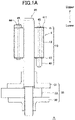
- Fig. 1A is a front elevational view of a rotor assembly A as an example in which the inner rotor according to the present invention is used.
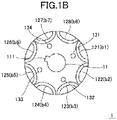
- Fig. 1B is a plan view of a rotor core 1 that is incorporated in the rotor assembly A.
- directions of the arrows illustrated in Fig. 1A represent the upper and lower directions.
- the rotor assembly A comprises an inner rotor 10, a rotating shaft 20, and a load body 30 (associated rotating body).
- Rotor core 1 that constitutes the inner rotor 10 is, as illustrated in Fig. 1B , and has a shaft hole 11 provided at the center and having a key groove 111, eight approximately U-shaped slots 121 to 128 (referred collectively to as a "slot 12" or “slots 12") that are arranged evenly around the shaft hole 11, and four rivet holes 131 to 134 (referred collectively to as a "rivet hole 13" or “rivet holes 13”) that are evenly arranged between the shaft hole 11 and the slots 12.
- the rotor core 1 is configured by stacking silicon steel plates punched out into a shape as illustrated in Fig. 1B .
- End plates 41 and 42 are fixed to the upper and lower end surfaces, respectively, of the rotor core 1.
- the end plates 41 and 42 close the upper and lower openings, respectively, of the slots 12 of the inner rotor 10.
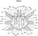
- the end plate 41 is formed with eight small filling holes 4111 to 4118 (referred collectively to as a “filling hole 411” or “filling holes 411,” see Fig. 5 ) that communicate respectively into the slots 121 to 128.
- balance weights 43 and 44 are fixed on the end plates 41 and 42, respectively.
- the rotor core 1, the end plates 41 and 42, and the balance weights 43 and 44 are fastened together using four rivets 451 to 454 (referred collectively to as a "rivet 45" or “rivets 45”) that penetrate the rivet holes 13.
- Anisotropic rare-earth bond magnets b1 to b8 are formed in respective slots 12 of the rotor core 1 by injection molding via the filling holes 411.
- the inner rotor 10 refers not only to the rotor core 1 and the anisotropic rare-earth bond magnets b but also to the end plates 41 and 42 and balance weights 43 and 44 which are fixed to the rotor core 1 using the above-described rivets 45.
- the load body 30, which is a driving part that drives a compressor for air conditioners, comprises flanges 31 and 32 and a crank 33 interposed between the flanges 31 and 32. They are in an outer form that projects in the radial direction than the inner rotor 10.
- the load body 30 is fixed to the rotating shaft 20 by press fitting (press fitting step) and the inner rotor 10 is fixed to the rotating shaft 20 by shrink fitting (shrink fitting step).
- shrink fitting the inner rotor 10 is fixed to the rotating shaft 20 such that the rotor core 1 is heated to about 200 to 500 degrees C and the rotating shaft 20 is inserted into the shaft hole 11.
- the rotor assembly A (before being filled with the anisotropic rare-earth bond magnets b) is thus formed.
- the slots 12 are filled with a flowable mixture from respective filling holes 411 (injection step) thereby to form the magnetic poles composed of the anisotropic rare-earth bond magnets b in the inner rotor 10.
- Transfer molding is also possible as substitute for the injection molding. While thermoplastic resin used in the injection molding is solidified by cooling, the thermoset resin used in the transfer molding is solidified by heating in a mold or by a curing process (heat treatment for hardening) after the transfer molding.
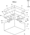
- the mold D has a three-layer structure of a holding mold 5, orienting mold 6, and injecting mold 7.
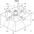
- the holding mold 5 is composed of a base 51, four slide cores 521 to 524 (referred collectively to as a “slide core 52" or “slide cores 52") that each slide so as to be movable forward and backward between the middle of each side of the base 51 and the center of the base 51, and guide pins 531 to 534 (referred collectively to as a "guide pin 53" or “guide pins 53”) that project in the vertical direction from the upper surface side of the base 51.
- the slide cores 52 are in an approximately rectangular column-like form and fitting holes 5211 to 5241 are formed in respective slide cores 52 each at the middle but rather near the outer side.
- Supporting parts 5212 to 5242 are formed at middle sides of respective slide cores 52 (center sides of the holding mold 5).
- the supporting parts 5212 to 5242 are located between the inner rotor 10 and load body 30 of the rotor assembly A to surround the rotating shaft 20 and support the end plate 42 from below.
- Middle and lower portion of the base 51 has a space (not illustrated) that houses the load body 30 fixed to the rotating shaft 20, and is further formed with a shaft hole (not illustrated) into which the lower end portion of the rotating shaft 20 is inserted.
- the orienting mold 6 has a base 61, four angular cams 621 to 624 (referred collectively to as an “angular cam 62" or “angular cams 62") that project from the lower surface side of the base 61 in downward oblique directions, oriented magnetic field body 63 that is disposed at the middle of the base 61, and guide holes 641 to 644 (referred collectively to as a “guide hole 64" or “guide holes 64") that fit respectively with the guide pins 531 to 534 provided at the upper surface side of the base 51 of the holding mold 5.
- the oriented magnetic field body 63 is composed of eight orienting yokes 6311 to 6318 (referred collectively to as an "orienting yoke 631" or “orienting yokes 631”) that project radially and slenderly toward the outer circumferential side, a cylindrical housing part 632 that bridges the orienting yokes 631 in a circular arc fashion and has an inner circumferential surface continuing smoothly at the middle, sixteen permanent magnets 6331a to 6338a (referred collectively to as a “permanent magnet 633a” or permanent magnets 633a”) and permanent magnets 6331b to 6338b (referred collectively to as a “permanent magnet 633b” or permanent magnets 633b”) that are to be oriented magnetic field sources arranged such that the same poles face the opposing side surfaces of each orienting yoke 631 in the circumferential direction, and a case 634 that houses the above components.
- the permanent magnets 6331a and the permanent magnets 6331b are disposed such that respective S poles are in contact with the side surfaces of the orienting yoke 6311 in the circumferential direction while the permanent magnets 6332a and the permanent magnets 6332b are disposed such that respective N poles are in contact with the side surfaces of the adjacent orienting yoke 6312 in the circumferential direction.
- Such an arrangement allows the oriented magnetic fields to be effectively applied in opposite directions to adjacent ones of the slots 12 of the rotor core 1 housed in the housing part 632.
- the injecting mold 7 is configured such that a flow channel (not illustrated) to be a path for the flowable mixture of anisotropic rare-earth magnet power and a binder resin (thermoplastic resin) is formed inside the middle of the base 71.
- This flow channel comprises a spool 721, eight runners 7221 to 7228 (referred collectively to as a "runner 722” or “runners 722”) that merge into the spool 721, and thin pin gates 7231 to 7238 (referred collectively to as a pin gate “723” or “pin gates 723”) that communicate into respective runners 722. End portions of the pin gates 723 are connected to respective filling holes 411 of the end plate 41 and the slots 12 are filled with the flowable mixture through the pin gates 723.
- the previously-described rotor assembly A (before being filled with the anisotropic rare-earth bond magnets b) is set with the load body 30 positioned at the lower side from above to the middle of the holding mold 5.
- the temperature of the rotor core 1 is to be a temperature (e.g. 130 to 160 degrees C) suitable for injection.
- temperature adjustment may be performed as necessary, such as by air cooling (temperature adjusting step).
- the slide cores 52 are moved toward the center of the holding mold 5 while at the same time the orienting mold moves down toward the holding mold 5.
- the orienting mold attracts the load body 30 by the magnetic attractive force.
- the upper end surface of the load body 30 comes into contact with the (inner circumferential) lower end surfaces of the supporting parts 5212 to 5242 and the supporting parts 5212 to 5242 surround the rotating shaft 20.
- This operation puts the rotor assembly A into a state in which its movement in the axial direction is provisionally constrained.
- the rotor assembly A is prevented from unexpectedly attaching to the oriented magnetic field body 63 by its magnetic force when the orienting mold 6 moves down toward the holding mold 5.
- the holding mold 5 and the orienting mold 6 ensures that the holding mold 5 holds the rotor assembly A, and the rotor core 1 is housed in the housing part 632 of the oriented magnetic field body 63. Since the oriented magnetic field body 63 uses the permanent magnets 633a and 633b (referred collectively to as "permanent magnets 633") as the oriented magnetic field sources, there is obtained a state in which a certain oriented magnetic fields are applied to each slot 12 at the stage when the rotor core 1 is housed in the housing part 632.
- the injecting mold 7 also moves downward in a cooperative manner with the orienting mold 6, and the lower surface of the injecting mold 7 and the upper surface of the orienting mold 6 come into close contact with each other.
- This operation causes a state in which the end part of each pin gate 723 is connected with the corresponding filling hole 411 of the end plate.
- the flowable mixture which is composed of anisotropic rare-earth magnet particles and a binder resin, is fed by pressure from the general-purpose vertical-type injection molding machine to the spool 721 and then filled into the slots 12 from respective filling holes 411 via respective runners 722 and pin gates 723.
- each slot 12 of the rotor core 1 is completely closed by the end plate 42, which is supported by the upper end sides of the supporting parts 5212 to 5242 of the slide cores 52, and the mold clamping force is thereby removably supported.
- Each anisotropic rare-earth bond magnet b is a permanent magnet obtained by injection molding in the state in which the strong oriented magnetic fields are applied thereto, and thus already exhibits a strong magnetic force even without being magnetized.
- the rotor assembly A is obtained, having the anisotropic rare-earth bond magnets b which are magnetized as the magnetic poles.
- An IPM motor can be obtained by incorporating this rotor assembly A into a stator. Movement of the orienting mold 6 and injecting mold 7 was performed using a driving means (mold clamping means), such as a hydraulic actuator, equipped in the general-purpose vertical-type injection molding machine.
Landscapes
- Engineering & Computer Science (AREA)
- Power Engineering (AREA)
- Manufacturing & Machinery (AREA)
- Permanent Field Magnets Of Synchronous Machinery (AREA)
- Manufacture Of Motors, Generators (AREA)
Claims (3)
- Appareil pour fabriquer un rotor interne (10) de type à aimant permanent, l'appareil comprenant :un moule (D) ayant une structure à trois couches d'un moule de maintien (5),d' un moule d'orientation (6), et d'un moule de remplissage (7) ;le moule de maintien (5) étant approprié pour maintenir un ensemble de noyau comprenant un arbre rotatif (20), un noyau rotorique (1) et un corps rotatif associé (30) à partir d'une première extrémité axiale à laquelle au moins le corps rotatif associé (30) est situé et pour supporter une surface d'extrémité axiale du noyau rotorique (1) située à ladite première extrémité axiale, le noyau rotorique (1) ayant une pluralité de fentes (121-128) disposées de manière régulière autour d'un trou d'arbre de noyau rotorique (11) dans lequel l'arbre rotatif (20) est ajusté, le corps rotatif associé (30) ayant une portion (31, 32) qui fait saillie au-delà d'un diamètre extérieur du noyau rotorique (1),le moule de maintien (5) comprenant une base (51) et des noyaux coulissants (521-524), chaque noyau coulissant (521-524) étant mobile vers l'avant et vers l'arrière entre un côté latéral de la base (51) et un centre de la base (51) ;le moule d'orientation (6) comprenant :- une base (61),- un corps de champ magnétique orienté (63), comprenant lui-même :- une partie de logement cylindrique (632) comprenant une ouverture traversante qui est appropriée pour loger le noyau rotorique (1) à partir d'une seconde extrémité axiale de l'ensemble de noyau,- une pluralité de culasses d'orientation (6311-6318) qui sont disposées de manière régulière autour de la partie de logement (632) et induisent des champs magnétiques orientés à appliquer aux fentes (121-128),- des aimants permanents (6331a-6338a, 6331b-6338b) qui sont des sources de champ magnétique orienté disposées autour des culasses d'orientation (631) ; etle moule de remplissage (7) étant approprié pour remplir un mélange fluide dans les fentes (121-128) à partir de la surface d'extrémité axiale du noyau rotorique (1) située à la seconde extrémité axiale lorsque le noyau rotorique (1) est logé dans la partie de logement (632) et que les champs magnétiques orientés sont appliqués audit noyau rotorique, le mélange fluide étant un mélange d'une résine liante chauffée à un état fluide et de particules d'aimant anisotrope, le mélange fluide étant approprié pour être solidifié en aimants à liaison anisotrope en tant que pôles magnétiques pour obtenir le rotor interne (10) de type à aimant permanent,dans lequel des parties de support (5212-5242) sont formées sur les côtés médians des noyaux coulissants respectifs (521-524), au centre du moule de maintien (5), et sont configurées pour être situées entre le rotor interne de type à aimant permanent (10) et le corps rotatif associé (30) pour entourer l'arbre rotatif (20) et pour supporter la surface d'extrémité axiale du noyau rotorique (1) située au niveau de ladite première extrémité axiale lorsque le moule d'orientation (6) est déplacé vers le moule de maintien (5) de sorte que les surfaces se faisant face du moule de maintien (5) et du moule d'orientation (6) se rapprochent l'une de l'autre, etdans lequel les noyaux coulissants (521-524) sont configurés pour empêcher l'ensemble de noyaux de se fixer inopinément au corps de champ magnétique orienté (63) par sa force magnétique lorsque le moule d'orientation (6) descend vers le moule de maintien (5).
- Procédé de fabrication d'un rotor interne (10) de type à aimant permanent intérieur, le procédé comprenant :une étape d'ajustement par rétraction consistant à chauffer un noyau rotorique (1) pourvu en son milieu d'un trou d'arbre (11) et à insérer un arbre rotatif (20) dans le trou d'arbre pour ajuster par rétraction le noyau rotorique (1) à l'arbre rotatif (20), le noyau rotorique (1) ayant une pluralité de fentes (121-128) disposées régulièrement autour du trou d'arbre (11), le noyau rotorique (1), l'arbre rotatif (20) et un corps rotatif associé (30) formant un ensemble de noyau, le corps rotatif associé (30) ayant une portion (31, 32) qui fait saillie au-delà d'un diamètre externe du noyau rotorique (1) ; etune étape de remplissage consistant à remplir les fentes (121-128) du noyau rotorique (1) dans un état de chaleur résiduelle après l'étape d'ajustement par rétraction avec un mélange fluide dans des champs magnétiques orientés, le mélange fluide étant un mélange d'une résine liante chauffée à un état fluide et de particules d'aimant anisotrope, formant des aimants à liaison anisotropes en tant que pôles magnétiques dans un état solidifié du mélange fluide,dans lequel l'étape de remplissage est effectuée en utilisant l'appareil de fabrication tel que décrit dans la revendication 1, dans lequel le moule de maintien (5) maintient l'ensemble de noyau à partir d'une première extrémité axiale à laquelle au moins le corps rotatif associé (30) est situé et supporte une surface d'extrémité axiale du noyau rotorique (1) situé à ladite première extrémité axiale, dans lequel le noyau rotorique (1) est logé dans l'ouverture traversante de la partie de logement cylindrique (632) depuis une seconde extrémité axiale de l'ensemble de noyau,dans lequel les noyaux coulissants (521-524) sont configurés pour empêcher l'ensemble de noyaux de se fixer inopinément au corps de champ magnétique orienté (63) par sa force magnétique lorsque le moule d'orientation (6) descend vers le moule de maintien (5), et dans lequel les parties de support (5212-5242) sont situées entre le rotor interne de type à aimant permanent (10) et le corps rotatif associé (30) pour entourer l'arbre rotatif (20) et pour supporter la surface d'extrémité axiale du noyau rotorique (1) située au niveau de ladite première extrémité axiale lorsque le moule d'orientation (6) est déplacé vers le moule de maintien (5) de sorte que les surfaces se faisant face du moule de maintien (5) et du moule d'orientation (6) se rapprochent l'une de l'autre.
- Procédé de fabrication d'un rotor interne (10) de type à aimant permanent selon la revendication 2, dans lequel les aimants à liaison anisotrope ne sont pas magnétisés après l'étape de remplissage.
Applications Claiming Priority (2)
| Application Number | Priority Date | Filing Date | Title |
|---|---|---|---|
| JP2014076484A JP5900528B2 (ja) | 2014-04-02 | 2014-04-02 | 内包磁石型インナーロータの製造装置 |
| PCT/JP2015/057390 WO2015151760A1 (fr) | 2014-04-02 | 2015-03-12 | Procédé de fabrication d'un rotor interne à aimants permanents internes et dispositif de fabrication de ce dernier |
Publications (3)
| Publication Number | Publication Date |
|---|---|
| EP3128657A1 EP3128657A1 (fr) | 2017-02-08 |
| EP3128657A4 EP3128657A4 (fr) | 2017-05-24 |
| EP3128657B1 true EP3128657B1 (fr) | 2022-05-04 |
Family
ID=54240092
Family Applications (1)
| Application Number | Title | Priority Date | Filing Date |
|---|---|---|---|
| EP15773191.0A Active EP3128657B1 (fr) | 2014-04-02 | 2015-03-12 | Procédé de fabrication d'un rotor interne à aimants permanents internes et dispositif de fabrication de ce dernier |
Country Status (5)
| Country | Link |
|---|---|
| US (2) | US10454353B2 (fr) |
| EP (1) | EP3128657B1 (fr) |
| JP (1) | JP5900528B2 (fr) |
| CN (1) | CN106165269B (fr) |
| WO (1) | WO2015151760A1 (fr) |
Families Citing this family (21)
| Publication number | Priority date | Publication date | Assignee | Title |
|---|---|---|---|---|
| JP5900528B2 (ja) * | 2014-04-02 | 2016-04-06 | 愛知製鋼株式会社 | 内包磁石型インナーロータの製造装置 |
| GR1008783B (el) | 2015-06-17 | 2016-06-09 | Γιαννης Χρηστου Στεφανιδης | Ενδαγγειακος καθετηρας στηριξης με κινουμενο μπαλονι |
| WO2017038326A1 (fr) * | 2015-09-02 | 2017-03-09 | 日立オートモティブシステムズ株式会社 | Rotor, machine électrique tournante équipée de celui-ci et procédé de fabrication de rotor |
| ES2979095T3 (es) | 2016-08-23 | 2024-09-24 | Shuttle Catheters Pc | Catéter de alambre guía dirigible a distancia endovascular |
| CN109789256B (zh) * | 2016-09-29 | 2021-08-03 | 心脏器械股份有限公司 | 可植入泵叶轮的热击倒 |
| CN106787516A (zh) * | 2017-01-17 | 2017-05-31 | 江苏新日电动车股份有限公司 | 一种永磁电机转子的制造方法 |
| DE102017104895B4 (de) * | 2017-03-08 | 2021-08-19 | Preh Gmbh | Formgebendes Verfahren zur Herstellung eines einen Permanentmagneten aufweisenden Verbundteils |
| CN106981958A (zh) * | 2017-05-23 | 2017-07-25 | 中达电机股份有限公司 | 一种内置式永磁同步电机转子装配方法 |
| CN110365146B (zh) * | 2018-03-26 | 2025-02-07 | 株式会社安川电机 | 电动机转子、电动机及电动机转子的装配方法 |
| CN110971091B (zh) * | 2018-09-30 | 2021-04-27 | 株洲中车机电科技有限公司 | 一种永磁电机转子永磁体装配装置及其装配方法 |
| CN209427692U (zh) * | 2018-10-09 | 2019-09-24 | 江门市星光自动化科技有限公司 | 电机转子的自动装盘机 |
| DE102019103920A1 (de) * | 2019-02-15 | 2020-08-20 | Fte Automotive Gmbh | Verfahren zur Herstellung eines Rotors für einen Elektromotor sowie Rotor für einen Elektromotor |
| US11961660B2 (en) | 2020-08-31 | 2024-04-16 | General Electric Company | Systems and methods for assembling a magnetic-core assembly |
| CN112436685B (zh) * | 2020-11-06 | 2024-02-20 | 兰州空间技术物理研究所 | 一种直线发电机动子磁钢的贴装工装及方法 |
| GR1010101B (el) * | 2020-12-18 | 2021-10-11 | Ιωαννης Χρηστου Στεφανιδης | Καθετηρας |
| GR1010093B (el) * | 2020-12-18 | 2021-09-30 | Ιωαννης Χρηστου Στεφανιδης | Καθετηρας |
| GR1010084B (el) * | 2020-12-18 | 2021-09-20 | Ιωαννης Χρηστου Στεφανιδης | Καθετηρας |
| CN113037035B (zh) * | 2021-04-30 | 2022-02-18 | 江苏中关赛恩汽车电机研究院有限公司 | 用于新能源汽车电机转子灌胶的工装 |
| CN113437843A (zh) * | 2021-07-09 | 2021-09-24 | 浙江盘毂动力科技有限公司 | 基于钕铁硼磁钢的转子结构及制造方法 |
| JP7571000B2 (ja) * | 2021-12-08 | 2024-10-22 | 本田技研工業株式会社 | 回転電機の永久磁石減磁方法、回転電機の永久磁石減磁システム、及び、ロータの取り出し方法 |
| WO2024029254A1 (fr) * | 2022-08-03 | 2024-02-08 | 株式会社アイシン | Procédé de fabrication de rotor pour machine électrique rotative et dispositif de fabrication de rotor pour machine électrique rotative |
Citations (1)
| Publication number | Priority date | Publication date | Assignee | Title |
|---|---|---|---|---|
| EP1793479B1 (fr) * | 2005-12-02 | 2010-01-20 | Fanuc Ltd | Moule pour la fabrication d'un rotor de moteur électrique |
Family Cites Families (23)
| Publication number | Priority date | Publication date | Assignee | Title |
|---|---|---|---|---|
| US5199171A (en) * | 1990-05-31 | 1993-04-06 | Mitsuba Electric Manufacturing Co., Ltd. | Method of manufacturing a motor casing made of resin |
| US5806169A (en) * | 1995-04-03 | 1998-09-15 | Trago; Bradley A. | Method of fabricating an injected molded motor assembly |
| JPH11206075A (ja) | 1998-01-13 | 1999-07-30 | Matsushita Electric Ind Co Ltd | 希土類樹脂磁石埋設型回転子の製造方法 |
| JP2000092762A (ja) | 1998-09-09 | 2000-03-31 | Toshiba Corp | 電動機の回転子 |
| JP2000166190A (ja) * | 1998-11-30 | 2000-06-16 | Toshiba Corp | 永久磁石形モータのロータ製造装置及び永久磁石形モータの製造方法 |
| JP2001355006A (ja) * | 2000-06-09 | 2001-12-25 | Sumitomo Special Metals Co Ltd | 複合構造体とその製造方法並びにモーター |
| JP2002044915A (ja) * | 2000-07-27 | 2002-02-08 | Yamaha Motor Co Ltd | 磁石埋込型回転子及び充填方法 |
| JP4091422B2 (ja) * | 2000-10-25 | 2008-05-28 | コンセプション エ デヴロップマン ミシュラン,ソシエテ アノニム | 回転電気装置と、その製造方法 |
| JP3741653B2 (ja) | 2002-02-20 | 2006-02-01 | 三菱電機株式会社 | 永久磁石形電動機の製造方法及び圧縮機及び冷凍サイクル装置及び永久磁石形電動機の製造装置及び永久磁石の熱減磁抑制具 |
| JP2003299291A (ja) | 2002-04-04 | 2003-10-17 | Matsushita Electric Ind Co Ltd | 密閉型圧縮機用電動機の固定子 |
| JP2004328963A (ja) * | 2003-04-28 | 2004-11-18 | Nissan Motor Co Ltd | 電動機の回転子の製造方法及び電動機の回転子 |
| CN1671025A (zh) * | 2004-03-19 | 2005-09-21 | 广东威灵电机制造有限公司 | 一种用于电动机的永磁转子及其制造方法 |
| US7281313B2 (en) * | 2004-10-04 | 2007-10-16 | Emerson Electric Co. | Electric machines and methods related to assembling electric machines |
| JP4143631B2 (ja) * | 2005-09-01 | 2008-09-03 | トヨタ自動車株式会社 | ロータの製造方法 |
| DE602006006298D1 (de) * | 2006-05-24 | 2009-05-28 | Ernesto Malvestiti S P A | Zentriereinrichtung für Stanzmatrizen |
| JP2008172965A (ja) * | 2007-01-15 | 2008-07-24 | Matsushita Electric Ind Co Ltd | 永久磁石回転子及びモータ並びに電気機器 |
| US7800276B2 (en) * | 2007-05-17 | 2010-09-21 | Kurz-Kasch, Inc. | Rotor assembly |
| JP5077167B2 (ja) * | 2008-09-18 | 2012-11-21 | トヨタ自動車株式会社 | ステータ製造システム |
| US20120049663A1 (en) * | 2010-09-01 | 2012-03-01 | Gm Global Technology Operations, Inc. | Rotor and method of forming same |
| JP5746873B2 (ja) * | 2011-02-02 | 2015-07-08 | 本田技研工業株式会社 | ロータの製造方法 |
| JP2014057433A (ja) * | 2012-09-12 | 2014-03-27 | Daikin Ind Ltd | 回転電気機械 |
| US9601976B2 (en) * | 2013-05-17 | 2017-03-21 | GM Global Technology Operations LLC | Method for injection molding rotor magnets |
| JP5900528B2 (ja) * | 2014-04-02 | 2016-04-06 | 愛知製鋼株式会社 | 内包磁石型インナーロータの製造装置 |
-
2014
- 2014-04-02 JP JP2014076484A patent/JP5900528B2/ja active Active
-
2015
- 2015-03-12 EP EP15773191.0A patent/EP3128657B1/fr active Active
- 2015-03-12 WO PCT/JP2015/057390 patent/WO2015151760A1/fr not_active Ceased
- 2015-03-12 CN CN201580018237.5A patent/CN106165269B/zh active Active
- 2015-03-12 US US15/300,904 patent/US10454353B2/en active Active
-
2019
- 2019-05-24 US US16/422,613 patent/US11165315B2/en active Active
Patent Citations (1)
| Publication number | Priority date | Publication date | Assignee | Title |
|---|---|---|---|---|
| EP1793479B1 (fr) * | 2005-12-02 | 2010-01-20 | Fanuc Ltd | Moule pour la fabrication d'un rotor de moteur électrique |
Also Published As
| Publication number | Publication date |
|---|---|
| US10454353B2 (en) | 2019-10-22 |
| EP3128657A4 (fr) | 2017-05-24 |
| US20170025933A1 (en) | 2017-01-26 |
| CN106165269B (zh) | 2018-10-26 |
| US20190280576A1 (en) | 2019-09-12 |
| WO2015151760A1 (fr) | 2015-10-08 |
| JP2015198540A (ja) | 2015-11-09 |
| CN106165269A (zh) | 2016-11-23 |
| EP3128657A1 (fr) | 2017-02-08 |
| US11165315B2 (en) | 2021-11-02 |
| JP5900528B2 (ja) | 2016-04-06 |
Similar Documents
| Publication | Publication Date | Title |
|---|---|---|
| US11165315B2 (en) | Method and apparatus for manufacturing interior permanent magnet-type inner rotor | |
| CN109638995B (zh) | 用于旋转电机的转子及其制造方法 | |
| EP2573917B1 (fr) | Procédé de production d'un rotor, et d'un moteur sans balais de type à rotor interne | |
| US10644576B2 (en) | Method for manufacturing an electrical machine | |
| EP2680403B1 (fr) | Moteur éléctrique ainsi que son procédé de fabrication | |
| AU2016300248B2 (en) | Rotor manufacturing method and rotor | |
| US10848037B2 (en) | Permanent magnet rotor, method for the production thereof using a magnetizing fixture | |
| JP2010200518A (ja) | 永久磁石回転機用回転盤及び永久磁石回転機の製造方法 | |
| US12562609B2 (en) | Rotor for an axial flux motor | |
| JP6575202B2 (ja) | 内包磁石型ロータの製造装置 | |
| JP7275707B2 (ja) | 磁石部材の製造装置およびその製造方法 | |
| JP2017507046A (ja) | 永久磁石を製造するための射出成形金型 | |
| JP6107299B2 (ja) | 内包磁石型同期機のアウターロータの製造方法 | |
| JP2016178784A (ja) | 磁石部材の製造装置およびその製造方法 | |
| EP3468002B1 (fr) | Rotor de moteur ipm, moteur ipm et procédé de fabrication de rotor de moteur ipm | |
| JP5975123B2 (ja) | 内包磁石型同期機およびその回転子 | |
| US20250119012A1 (en) | Molded Rotor | |
| US20260088669A1 (en) | Method for manufacturing rotor |
Legal Events
| Date | Code | Title | Description |
|---|---|---|---|
| STAA | Information on the status of an ep patent application or granted ep patent |
Free format text: STATUS: THE INTERNATIONAL PUBLICATION HAS BEEN MADE |
|
| PUAI | Public reference made under article 153(3) epc to a published international application that has entered the european phase |
Free format text: ORIGINAL CODE: 0009012 |
|
| STAA | Information on the status of an ep patent application or granted ep patent |
Free format text: STATUS: REQUEST FOR EXAMINATION WAS MADE |
|
| 17P | Request for examination filed |
Effective date: 20160928 |
|
| AK | Designated contracting states |
Kind code of ref document: A1 Designated state(s): AL AT BE BG CH CY CZ DE DK EE ES FI FR GB GR HR HU IE IS IT LI LT LU LV MC MK MT NL NO PL PT RO RS SE SI SK SM TR |
|
| AX | Request for extension of the european patent |
Extension state: BA ME |
|
| RIC1 | Information provided on ipc code assigned before grant |
Ipc: H01F 13/00 20060101ALN20170413BHEP Ipc: H02K 15/03 20060101AFI20170413BHEP Ipc: H02K 1/27 20060101ALN20170413BHEP Ipc: H01F 41/02 20060101ALN20170413BHEP |
|
| A4 | Supplementary search report drawn up and despatched |
Effective date: 20170424 |
|
| DAV | Request for validation of the european patent (deleted) | ||
| DAX | Request for extension of the european patent (deleted) | ||
| STAA | Information on the status of an ep patent application or granted ep patent |
Free format text: STATUS: EXAMINATION IS IN PROGRESS |
|
| 17Q | First examination report despatched |
Effective date: 20190730 |
|
| REG | Reference to a national code |
Ref country code: DE Ref legal event code: R079 Ref document number: 602015078712 Country of ref document: DE Free format text: PREVIOUS MAIN CLASS: H02K0015020000 Ipc: H02K0015030000 |
|
| GRAP | Despatch of communication of intention to grant a patent |
Free format text: ORIGINAL CODE: EPIDOSNIGR1 |
|
| STAA | Information on the status of an ep patent application or granted ep patent |
Free format text: STATUS: GRANT OF PATENT IS INTENDED |
|
| RIC1 | Information provided on ipc code assigned before grant |
Ipc: H02K 1/276 20220101ALN20220203BHEP Ipc: H01F 41/02 20060101ALN20220203BHEP Ipc: H01F 13/00 20060101ALN20220203BHEP Ipc: H02K 15/03 20060101AFI20220203BHEP |
|
| GRAS | Grant fee paid |
Free format text: ORIGINAL CODE: EPIDOSNIGR3 |
|
| INTG | Intention to grant announced |
Effective date: 20220302 |
|
| GRAA | (expected) grant |
Free format text: ORIGINAL CODE: 0009210 |
|
| STAA | Information on the status of an ep patent application or granted ep patent |
Free format text: STATUS: THE PATENT HAS BEEN GRANTED |
|
| AK | Designated contracting states |
Kind code of ref document: B1 Designated state(s): AL AT BE BG CH CY CZ DE DK EE ES FI FR GB GR HR HU IE IS IT LI LT LU LV MC MK MT NL NO PL PT RO RS SE SI SK SM TR |
|
| REG | Reference to a national code |
Ref country code: GB Ref legal event code: FG4D |
|
| REG | Reference to a national code |
Ref country code: CH Ref legal event code: EP |
|
| REG | Reference to a national code |
Ref country code: AT Ref legal event code: REF Ref document number: 1490185 Country of ref document: AT Kind code of ref document: T Effective date: 20220515 |
|
| REG | Reference to a national code |
Ref country code: DE Ref legal event code: R096 Ref document number: 602015078712 Country of ref document: DE |
|
| REG | Reference to a national code |
Ref country code: IE Ref legal event code: FG4D |
|
| REG | Reference to a national code |
Ref country code: LT Ref legal event code: MG9D |
|
| REG | Reference to a national code |
Ref country code: NL Ref legal event code: MP Effective date: 20220504 |
|
| REG | Reference to a national code |
Ref country code: AT Ref legal event code: MK05 Ref document number: 1490185 Country of ref document: AT Kind code of ref document: T Effective date: 20220504 |
|
| PG25 | Lapsed in a contracting state [announced via postgrant information from national office to epo] |
Ref country code: SE Free format text: LAPSE BECAUSE OF FAILURE TO SUBMIT A TRANSLATION OF THE DESCRIPTION OR TO PAY THE FEE WITHIN THE PRESCRIBED TIME-LIMIT Effective date: 20220504 Ref country code: PT Free format text: LAPSE BECAUSE OF FAILURE TO SUBMIT A TRANSLATION OF THE DESCRIPTION OR TO PAY THE FEE WITHIN THE PRESCRIBED TIME-LIMIT Effective date: 20220905 Ref country code: NO Free format text: LAPSE BECAUSE OF FAILURE TO SUBMIT A TRANSLATION OF THE DESCRIPTION OR TO PAY THE FEE WITHIN THE PRESCRIBED TIME-LIMIT Effective date: 20220804 Ref country code: NL Free format text: LAPSE BECAUSE OF FAILURE TO SUBMIT A TRANSLATION OF THE DESCRIPTION OR TO PAY THE FEE WITHIN THE PRESCRIBED TIME-LIMIT Effective date: 20220504 Ref country code: LT Free format text: LAPSE BECAUSE OF FAILURE TO SUBMIT A TRANSLATION OF THE DESCRIPTION OR TO PAY THE FEE WITHIN THE PRESCRIBED TIME-LIMIT Effective date: 20220504 Ref country code: HR Free format text: LAPSE BECAUSE OF FAILURE TO SUBMIT A TRANSLATION OF THE DESCRIPTION OR TO PAY THE FEE WITHIN THE PRESCRIBED TIME-LIMIT Effective date: 20220504 Ref country code: GR Free format text: LAPSE BECAUSE OF FAILURE TO SUBMIT A TRANSLATION OF THE DESCRIPTION OR TO PAY THE FEE WITHIN THE PRESCRIBED TIME-LIMIT Effective date: 20220805 Ref country code: FI Free format text: LAPSE BECAUSE OF FAILURE TO SUBMIT A TRANSLATION OF THE DESCRIPTION OR TO PAY THE FEE WITHIN THE PRESCRIBED TIME-LIMIT Effective date: 20220504 Ref country code: ES Free format text: LAPSE BECAUSE OF FAILURE TO SUBMIT A TRANSLATION OF THE DESCRIPTION OR TO PAY THE FEE WITHIN THE PRESCRIBED TIME-LIMIT Effective date: 20220504 Ref country code: BG Free format text: LAPSE BECAUSE OF FAILURE TO SUBMIT A TRANSLATION OF THE DESCRIPTION OR TO PAY THE FEE WITHIN THE PRESCRIBED TIME-LIMIT Effective date: 20220804 Ref country code: AT Free format text: LAPSE BECAUSE OF FAILURE TO SUBMIT A TRANSLATION OF THE DESCRIPTION OR TO PAY THE FEE WITHIN THE PRESCRIBED TIME-LIMIT Effective date: 20220504 |
|
| PG25 | Lapsed in a contracting state [announced via postgrant information from national office to epo] |
Ref country code: RS Free format text: LAPSE BECAUSE OF FAILURE TO SUBMIT A TRANSLATION OF THE DESCRIPTION OR TO PAY THE FEE WITHIN THE PRESCRIBED TIME-LIMIT Effective date: 20220504 Ref country code: PL Free format text: LAPSE BECAUSE OF FAILURE TO SUBMIT A TRANSLATION OF THE DESCRIPTION OR TO PAY THE FEE WITHIN THE PRESCRIBED TIME-LIMIT Effective date: 20220504 Ref country code: LV Free format text: LAPSE BECAUSE OF FAILURE TO SUBMIT A TRANSLATION OF THE DESCRIPTION OR TO PAY THE FEE WITHIN THE PRESCRIBED TIME-LIMIT Effective date: 20220504 Ref country code: IS Free format text: LAPSE BECAUSE OF FAILURE TO SUBMIT A TRANSLATION OF THE DESCRIPTION OR TO PAY THE FEE WITHIN THE PRESCRIBED TIME-LIMIT Effective date: 20220904 |
|
| PG25 | Lapsed in a contracting state [announced via postgrant information from national office to epo] |
Ref country code: SM Free format text: LAPSE BECAUSE OF FAILURE TO SUBMIT A TRANSLATION OF THE DESCRIPTION OR TO PAY THE FEE WITHIN THE PRESCRIBED TIME-LIMIT Effective date: 20220504 Ref country code: SK Free format text: LAPSE BECAUSE OF FAILURE TO SUBMIT A TRANSLATION OF THE DESCRIPTION OR TO PAY THE FEE WITHIN THE PRESCRIBED TIME-LIMIT Effective date: 20220504 Ref country code: RO Free format text: LAPSE BECAUSE OF FAILURE TO SUBMIT A TRANSLATION OF THE DESCRIPTION OR TO PAY THE FEE WITHIN THE PRESCRIBED TIME-LIMIT Effective date: 20220504 Ref country code: EE Free format text: LAPSE BECAUSE OF FAILURE TO SUBMIT A TRANSLATION OF THE DESCRIPTION OR TO PAY THE FEE WITHIN THE PRESCRIBED TIME-LIMIT Effective date: 20220504 Ref country code: DK Free format text: LAPSE BECAUSE OF FAILURE TO SUBMIT A TRANSLATION OF THE DESCRIPTION OR TO PAY THE FEE WITHIN THE PRESCRIBED TIME-LIMIT Effective date: 20220504 Ref country code: CZ Free format text: LAPSE BECAUSE OF FAILURE TO SUBMIT A TRANSLATION OF THE DESCRIPTION OR TO PAY THE FEE WITHIN THE PRESCRIBED TIME-LIMIT Effective date: 20220504 |
|
| REG | Reference to a national code |
Ref country code: DE Ref legal event code: R097 Ref document number: 602015078712 Country of ref document: DE |
|
| PLBE | No opposition filed within time limit |
Free format text: ORIGINAL CODE: 0009261 |
|
| STAA | Information on the status of an ep patent application or granted ep patent |
Free format text: STATUS: NO OPPOSITION FILED WITHIN TIME LIMIT |
|
| PG25 | Lapsed in a contracting state [announced via postgrant information from national office to epo] |
Ref country code: AL Free format text: LAPSE BECAUSE OF FAILURE TO SUBMIT A TRANSLATION OF THE DESCRIPTION OR TO PAY THE FEE WITHIN THE PRESCRIBED TIME-LIMIT Effective date: 20220504 |
|
| 26N | No opposition filed |
Effective date: 20230207 |
|
| PG25 | Lapsed in a contracting state [announced via postgrant information from national office to epo] |
Ref country code: SI Free format text: LAPSE BECAUSE OF FAILURE TO SUBMIT A TRANSLATION OF THE DESCRIPTION OR TO PAY THE FEE WITHIN THE PRESCRIBED TIME-LIMIT Effective date: 20220504 |
|
| P01 | Opt-out of the competence of the unified patent court (upc) registered |
Effective date: 20230413 |
|
| PG25 | Lapsed in a contracting state [announced via postgrant information from national office to epo] |
Ref country code: MC Free format text: LAPSE BECAUSE OF FAILURE TO SUBMIT A TRANSLATION OF THE DESCRIPTION OR TO PAY THE FEE WITHIN THE PRESCRIBED TIME-LIMIT Effective date: 20220504 |
|
| REG | Reference to a national code |
Ref country code: CH Ref legal event code: PL |
|
| REG | Reference to a national code |
Ref country code: BE Ref legal event code: MM Effective date: 20230331 |
|
| PG25 | Lapsed in a contracting state [announced via postgrant information from national office to epo] |
Ref country code: LU Free format text: LAPSE BECAUSE OF NON-PAYMENT OF DUE FEES Effective date: 20230312 |
|
| REG | Reference to a national code |
Ref country code: IE Ref legal event code: MM4A |
|
| PG25 | Lapsed in a contracting state [announced via postgrant information from national office to epo] |
Ref country code: LI Free format text: LAPSE BECAUSE OF NON-PAYMENT OF DUE FEES Effective date: 20230331 Ref country code: IT Free format text: LAPSE BECAUSE OF FAILURE TO SUBMIT A TRANSLATION OF THE DESCRIPTION OR TO PAY THE FEE WITHIN THE PRESCRIBED TIME-LIMIT Effective date: 20220504 Ref country code: IE Free format text: LAPSE BECAUSE OF NON-PAYMENT OF DUE FEES Effective date: 20230312 Ref country code: CH Free format text: LAPSE BECAUSE OF NON-PAYMENT OF DUE FEES Effective date: 20230331 |
|
| PG25 | Lapsed in a contracting state [announced via postgrant information from national office to epo] |
Ref country code: BE Free format text: LAPSE BECAUSE OF NON-PAYMENT OF DUE FEES Effective date: 20230331 |
|
| PGFP | Annual fee paid to national office [announced via postgrant information from national office to epo] |
Ref country code: DE Payment date: 20240320 Year of fee payment: 10 Ref country code: GB Payment date: 20240320 Year of fee payment: 10 |
|
| PGFP | Annual fee paid to national office [announced via postgrant information from national office to epo] |
Ref country code: FR Payment date: 20240328 Year of fee payment: 10 |
|
| PG25 | Lapsed in a contracting state [announced via postgrant information from national office to epo] |
Ref country code: BG Free format text: LAPSE BECAUSE OF FAILURE TO SUBMIT A TRANSLATION OF THE DESCRIPTION OR TO PAY THE FEE WITHIN THE PRESCRIBED TIME-LIMIT Effective date: 20220504 |
|
| PG25 | Lapsed in a contracting state [announced via postgrant information from national office to epo] |
Ref country code: BG Free format text: LAPSE BECAUSE OF FAILURE TO SUBMIT A TRANSLATION OF THE DESCRIPTION OR TO PAY THE FEE WITHIN THE PRESCRIBED TIME-LIMIT Effective date: 20220504 |
|
| PG25 | Lapsed in a contracting state [announced via postgrant information from national office to epo] |
Ref country code: CY Free format text: LAPSE BECAUSE OF FAILURE TO SUBMIT A TRANSLATION OF THE DESCRIPTION OR TO PAY THE FEE WITHIN THE PRESCRIBED TIME-LIMIT; INVALID AB INITIO Effective date: 20150312 |
|
| PG25 | Lapsed in a contracting state [announced via postgrant information from national office to epo] |
Ref country code: HU Free format text: LAPSE BECAUSE OF FAILURE TO SUBMIT A TRANSLATION OF THE DESCRIPTION OR TO PAY THE FEE WITHIN THE PRESCRIBED TIME-LIMIT; INVALID AB INITIO Effective date: 20150312 |
|
| REG | Reference to a national code |
Ref country code: DE Ref legal event code: R119 Ref document number: 602015078712 Country of ref document: DE |
|
| GBPC | Gb: european patent ceased through non-payment of renewal fee |
Effective date: 20250312 |
|
| PG25 | Lapsed in a contracting state [announced via postgrant information from national office to epo] |
Ref country code: TR Free format text: LAPSE BECAUSE OF FAILURE TO SUBMIT A TRANSLATION OF THE DESCRIPTION OR TO PAY THE FEE WITHIN THE PRESCRIBED TIME-LIMIT Effective date: 20220504 |
|
| PG25 | Lapsed in a contracting state [announced via postgrant information from national office to epo] |
Ref country code: DE Free format text: LAPSE BECAUSE OF NON-PAYMENT OF DUE FEES Effective date: 20251001 |
|
| PG25 | Lapsed in a contracting state [announced via postgrant information from national office to epo] |
Ref country code: GB Free format text: LAPSE BECAUSE OF NON-PAYMENT OF DUE FEES Effective date: 20250312 |
|
| PG25 | Lapsed in a contracting state [announced via postgrant information from national office to epo] |
Ref country code: FR Free format text: LAPSE BECAUSE OF NON-PAYMENT OF DUE FEES Effective date: 20250331 |