EP3128659A1 - Appareil de réfrigération - Google Patents
Appareil de réfrigération Download PDFInfo
- Publication number
- EP3128659A1 EP3128659A1 EP16181410.8A EP16181410A EP3128659A1 EP 3128659 A1 EP3128659 A1 EP 3128659A1 EP 16181410 A EP16181410 A EP 16181410A EP 3128659 A1 EP3128659 A1 EP 3128659A1
- Authority
- EP
- European Patent Office
- Prior art keywords
- rotor
- refrigeration apparatus
- alternating current
- motor
- stator
- Prior art date
- Legal status (The legal status is an assumption and is not a legal conclusion. Google has not performed a legal analysis and makes no representation as to the accuracy of the status listed.)
- Withdrawn
Links
- 238000005057 refrigeration Methods 0.000 title claims abstract description 32
- 230000001360 synchronised effect Effects 0.000 claims abstract description 41
- 238000004804 winding Methods 0.000 claims description 28
- 230000002457 bidirectional effect Effects 0.000 claims description 26
- 230000003247 decreasing effect Effects 0.000 claims description 5
- 230000007423 decrease Effects 0.000 claims description 4
- 238000010586 diagram Methods 0.000 description 8
- 230000009467 reduction Effects 0.000 description 5
- 230000008859 change Effects 0.000 description 3
- 230000006698 induction Effects 0.000 description 2
- 238000003475 lamination Methods 0.000 description 2
- 238000000034 method Methods 0.000 description 2
- 230000008569 process Effects 0.000 description 2
- 229910000976 Electrical steel Inorganic materials 0.000 description 1
- 238000001816 cooling Methods 0.000 description 1
- 238000002474 experimental method Methods 0.000 description 1
- 239000000696 magnetic material Substances 0.000 description 1
- 238000012986 modification Methods 0.000 description 1
- 230000004048 modification Effects 0.000 description 1
- 239000004065 semiconductor Substances 0.000 description 1
- 238000005476 soldering Methods 0.000 description 1
- 239000000758 substrate Substances 0.000 description 1
Images


Classifications
-
- H—ELECTRICITY
- H02—GENERATION; CONVERSION OR DISTRIBUTION OF ELECTRIC POWER
- H02K—DYNAMO-ELECTRIC MACHINES
- H02K29/00—Motors or generators having non-mechanical commutating devices, e.g. discharge tubes or semiconductor devices
- H02K29/03—Motors or generators having non-mechanical commutating devices, e.g. discharge tubes or semiconductor devices with a magnetic circuit specially adapted for avoiding torque ripples or self-starting problems
-
- H—ELECTRICITY
- H02—GENERATION; CONVERSION OR DISTRIBUTION OF ELECTRIC POWER
- H02K—DYNAMO-ELECTRIC MACHINES
- H02K1/00—Details of the magnetic circuit
- H02K1/06—Details of the magnetic circuit characterised by the shape, form or construction
- H02K1/22—Rotating parts of the magnetic circuit
- H02K1/27—Rotor cores with permanent magnets
- H02K1/2706—Inner rotors
- H02K1/272—Inner rotors the magnetisation axis of the magnets being perpendicular to the rotor axis
- H02K1/274—Inner rotors the magnetisation axis of the magnets being perpendicular to the rotor axis the rotor consisting of two or more circumferentially positioned magnets
- H02K1/2753—Inner rotors the magnetisation axis of the magnets being perpendicular to the rotor axis the rotor consisting of two or more circumferentially positioned magnets the rotor consisting of magnets or groups of magnets arranged with alternating polarity
- H02K1/278—Surface mounted magnets; Inset magnets
-
- F—MECHANICAL ENGINEERING; LIGHTING; HEATING; WEAPONS; BLASTING
- F25—REFRIGERATION OR COOLING; COMBINED HEATING AND REFRIGERATION SYSTEMS; HEAT PUMP SYSTEMS; MANUFACTURE OR STORAGE OF ICE; LIQUEFACTION SOLIDIFICATION OF GASES
- F25B—REFRIGERATION MACHINES, PLANTS OR SYSTEMS; COMBINED HEATING AND REFRIGERATION SYSTEMS; HEAT PUMP SYSTEMS
- F25B30/00—Heat pumps
- F25B30/02—Heat pumps of the compression type
-
- H—ELECTRICITY
- H02—GENERATION; CONVERSION OR DISTRIBUTION OF ELECTRIC POWER
- H02K—DYNAMO-ELECTRIC MACHINES
- H02K1/00—Details of the magnetic circuit
- H02K1/06—Details of the magnetic circuit characterised by the shape, form or construction
- H02K1/12—Stationary parts of the magnetic circuit
- H02K1/14—Stator cores with salient poles
- H02K1/146—Stator cores with salient poles consisting of a generally annular yoke with salient poles
- H02K1/148—Sectional cores
-
- H—ELECTRICITY
- H02—GENERATION; CONVERSION OR DISTRIBUTION OF ELECTRIC POWER
- H02K—DYNAMO-ELECTRIC MACHINES
- H02K21/00—Synchronous motors having permanent magnets; Synchronous generators having permanent magnets
- H02K21/12—Synchronous motors having permanent magnets; Synchronous generators having permanent magnets with stationary armatures and rotating magnets
- H02K21/14—Synchronous motors having permanent magnets; Synchronous generators having permanent magnets with stationary armatures and rotating magnets with magnets rotating within the armatures
- H02K21/16—Synchronous motors having permanent magnets; Synchronous generators having permanent magnets with stationary armatures and rotating magnets with magnets rotating within the armatures having annular armature cores with salient poles
-
- H—ELECTRICITY
- H02—GENERATION; CONVERSION OR DISTRIBUTION OF ELECTRIC POWER
- H02P—CONTROL OR REGULATION OF ELECTRIC MOTORS, ELECTRIC GENERATORS OR DYNAMO-ELECTRIC CONVERTERS; CONTROLLING TRANSFORMERS, REACTORS OR CHOKE COILS
- H02P6/00—Arrangements for controlling synchronous motors or other dynamo-electric motors using electronic commutation dependent on the rotor position; Electronic commutators therefor
- H02P6/26—Arrangements for controlling single phase motors
-
- F—MECHANICAL ENGINEERING; LIGHTING; HEATING; WEAPONS; BLASTING
- F25—REFRIGERATION OR COOLING; COMBINED HEATING AND REFRIGERATION SYSTEMS; HEAT PUMP SYSTEMS; MANUFACTURE OR STORAGE OF ICE; LIQUEFACTION SOLIDIFICATION OF GASES
- F25B—REFRIGERATION MACHINES, PLANTS OR SYSTEMS; COMBINED HEATING AND REFRIGERATION SYSTEMS; HEAT PUMP SYSTEMS
- F25B40/00—Subcoolers, desuperheaters or superheaters
- F25B40/06—Superheaters
-
- F—MECHANICAL ENGINEERING; LIGHTING; HEATING; WEAPONS; BLASTING
- F25—REFRIGERATION OR COOLING; COMBINED HEATING AND REFRIGERATION SYSTEMS; HEAT PUMP SYSTEMS; MANUFACTURE OR STORAGE OF ICE; LIQUEFACTION SOLIDIFICATION OF GASES
- F25B—REFRIGERATION MACHINES, PLANTS OR SYSTEMS; COMBINED HEATING AND REFRIGERATION SYSTEMS; HEAT PUMP SYSTEMS
- F25B5/00—Compression machines, plants or systems, with several evaporator circuits, e.g. for varying refrigerating capacity
- F25B5/04—Compression machines, plants or systems, with several evaporator circuits, e.g. for varying refrigerating capacity arranged in series
-
- H—ELECTRICITY
- H02—GENERATION; CONVERSION OR DISTRIBUTION OF ELECTRIC POWER
- H02K—DYNAMO-ELECTRIC MACHINES
- H02K2201/00—Specific aspects not provided for in the other groups of this subclass relating to the magnetic circuits
- H02K2201/03—Machines characterised by aspects of the air-gap between rotor and stator
-
- H—ELECTRICITY
- H02—GENERATION; CONVERSION OR DISTRIBUTION OF ELECTRIC POWER
- H02K—DYNAMO-ELECTRIC MACHINES
- H02K2213/00—Specific aspects, not otherwise provided for and not covered by codes H02K2201/00 - H02K2211/00
- H02K2213/03—Machines characterised by numerical values, ranges, mathematical expressions or similar information
-
- H—ELECTRICITY
- H02—GENERATION; CONVERSION OR DISTRIBUTION OF ELECTRIC POWER
- H02P—CONTROL OR REGULATION OF ELECTRIC MOTORS, ELECTRIC GENERATORS OR DYNAMO-ELECTRIC CONVERTERS; CONTROLLING TRANSFORMERS, REACTORS OR CHOKE COILS
- H02P6/00—Arrangements for controlling synchronous motors or other dynamo-electric motors using electronic commutation dependent on the rotor position; Electronic commutators therefor
- H02P6/20—Arrangements for starting
- H02P6/22—Arrangements for starting in a selected direction of rotation
Definitions
- the present invention relates to refrigeration apparatus, and in particular to a refrigeration apparatus having a single phase synchronous alternating current motor.
- a cooling fan of a refrigeration apparatus such as a freezer or refrigerator, includes a motor.
- the structure, size and cost of the motor affect the structure and cost of the whole refrigeration apparatus. How to balance between cost and motor performance has become a main subject of motor design.
- a refrigeration apparatus includes a fan and a motor for driving the fan.
- the motor is a single phase synchronous alternating current motor.
- the single phase synchronous alternating current motor includes a stator and a rotor rotatable relative to the stator.
- the stator includes a stator core and windings wound around the stator core.
- the stator core includes an outer ring portion, a plurality of tooth bodies extending inwardly from the outer ring portion, and a pole shoe extending from a distal end to two circumferential sides of each tooth body.
- the windings are wound around the respective tooth bodies.
- the rotor is received in a space cooperatively defined by the pole shoes and includes a plurality of permanent magnetic poles disposed along a circumferential direction of the rotor. An outer surface of the permanent magnetic pole and an inner circumferential surface of the pole shoe form a symmetrical uneven air gap therebetween.
- each permanent magnetic pole is spaced from a central axis of the rotor by a distance progressively decreasing from a circumferential center to two circumferential sides of the outer surface, and the air gap is symmetrical about a center line of one of the permanent magnetic poles.
- each permanent magnetic pole is formed by one or more permanent magnet members, or all permanent magnetic poles are formed by a single ring shaped magnetic member
- the rotor comprises a rotor core
- the one or more permanent magnetic members are mounted to an outer circumferential surface of the rotor core
- the outer circumferential surface of the rotor core defines a plurality of axially extending grooves, and each groove is located at a junction between two permanent magnetic poles.
- the one or more permanent magnetic members have a uniform thickness, and the outer circumferential surface of the rotor core matches with the one or more permanent magnet members in shape.
- the outer circumferential surface of the rotor core and an inner circumferential surface of the one or more permanent magnet members are located on a same cylindrical surface, and each permanent magnet member has a thickness progressively decreasing from a circumferential center to two circumferential ends of the permanent magnet member.
- a radial thickness of the pole shoe progressively decreases in a direction away from the tooth body.
- the symmetrical uneven air gap has a maximum thickness that is at least 1.5 times of its minimum thickness.
- a slot is formed between each two adjacent pole shoes, and a width of the slot is greater than zero and less than or equal to four times of a minimum thickness of the symmetrical uneven air gap.
- a width of the slot is greater than zero and less than or equal to two times of the minimum thickness of the symmetrical uneven air gap.
- the single phase synchronous alternating current motor is powered by an alternating current power source
- the single phase synchronous alternating current motor comprises a stator, a rotor rotatable relative to the stator, and a driving circuit
- the stator comprising a stator core and windings wound around the stator core
- the driving circuit comprises an integrated circuit and a controllable bidirectional alternating current switch connected with the integrated circuit
- the controllable bidirectional alternating current switch and the windings are connected in series between two terminals which are configured to be connected to the alternating power source
- at least two of a rectifier, a detecting circuit and a switch control circuit are integrated in the integrated circuit
- the rectifier is configured to produce a direct current voltage at least for the detecting circuit
- the detecting circuit is configured to detect a polarity of a magnetic field of the rotor
- the switch control circuit is configured to control the controllable bidirectional alternating current switch to be switched between turn-on and turn-off states according to a predetermined manner
- the switch control circuit is configured to control the controllable bidirectional alternating current switch to turn on only when the alternating current power source operates in a positive half cycle and the detecting circuit detects a first polarity of the magnetic field of the rotor, or when the alternating current power source operates in a negative half cycle and the detecting circuit detects a second polarity of the magnetic field of the rotor, the second polarity being opposite to the first polarity.
- the refrigeration apparatus is a freezer.
- the single phase synchronous alternating current motor rotates at a constant 1800RPM or 1500RPM speed in a steady state.
- the single phase synchronous alternating current motor has an input voltage of 120v or 220 to 230V, an input power of 6 to 20W, and an efficiency of 50% to 80%.
- the refrigeration apparatus of the present invention includes the single phase synchronous alternating current motor in its interior for driving the fan.
- the single phase synchronous alternating current motor has a reduced size and reduced cost, while ensuring the stable performance.
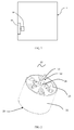
- the refrigeration apparatus 1 of the present invention includes a fan 90 and a single phase synchronous alternating current (AC) motor 10 for driving the fan 90.
- the refrigeration apparatus 1 may be a refrigerator or a freezer.
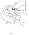
- the single phase synchronous AC motor 10 in accordance with a preferred embodiment of the present invention includes a stator 20 and a rotor 50 rotatable relative to the stator 20.
- the stator 20 includes a cylindrical outer housing 21 with one open end, an end cap 23 mounted to the open end of the outer housing 21, a stator core 30 mounted in the outer housing 21, an insulating bracket 40 mounted to the stator core 30, and windings 39 wound around the stator core 30 and supported by the insulating bracket 40.
- the stator core 30 includes an outer ring portion 31, a plurality of tooth bodies 33 extending inwardly from the outer ring portion 31, a pole shoe 35 extending from a radial distal end to two circumferential sides of each tooth body 33.
- the windings 39 are wound around the corresponding tooth bodies 33, and are isolated from the stator core 30 by the insulating bracket 40.
- the rotor 50 is received in a space cooperatively defined by the pole shoes 35 of the tooth bodies.
- the rotor 50 includes a plurality of permanent magnetic poles 55 disposed along a circumferential direction of the rotor.
- An outer surface of each permanent magnetic pole 55 is an arc surface.
- the outer surface of each permanent magnetic pole 55 is spaced from a central axis of the rotor 50 by a distance progressively decreasing from a circumferential center to two circumferential sides of the outer surface.
- the outer surface of the permanent magnetic pole 55 and an inner circumferential surface of the pole shoe 35 form an uneven air gap 41 therebetween that is symmetrical about a center line of the permanent magnetic pole 55.
- the symmetrical uneven air gap 41 has a maximum thickness that is at least 1.5 times of its minimum thickness.
- each permanent magnetic pole 55 is formed by a single permanent magnet member 56.
- the rotor 50 further includes a rotor core 53.
- the permanent magnet member 56 is mounted to an outer circumferential surface of the rotor core 53.
- the outer circumferential surface of the rotor core 53 defines a plurality of axially extending grooves 54.
- Each groove 54 is located at a junction between two permanent magnetic poles 55 to reduce magnetic leakage.
- the outer circumferential surface of the rotor core 53 and the inner circumferential surface of the pole shoe 35 are located on two concentric circles in an axial plan view, and a thickness of the permanent magnet member 56 progressively decreases from a circumferential center to two circumferential ends of the permanent magnet member 56.
- the rotor 50 further includes a rotary shaft 51 passing through and fixed to the rotor core 53.
- One end of the rotary shaft 51 is mounted to the end cap 23 through a bearing 24, and the other end of the rotary shaft 51 is mounted to a bottom of the cylindrical outer housing 21 of the stator 20 through another bearing, such that the rotor 50 is capable of rotation relative to the stator 20.
- the stator core 30 is made from a magnetic-conductive magnetic material.
- the stator core 30 is formed by stacking magnetic laminations (silicon steel laminations commonly used in the industry) along an axial direction of the motor.
- a slot 37 is formed between every two adjacent pole shoes 35.
- each slot 37 is located at a middle position between two adjacent tooth bodies 33. It should be understood that the slot 37 may be offset from the middle position between the two adjacent tooth bodies. This design can reduce the induction potential of the motor, thus increasing the output torque of the motor.
- the slot 37 has a width greater than zero and less or equal to four times of a minimum thickness of the symmetrical uneven air gap 41.
- the width of the slot 37 is greater than zero and less than or equal to two times of the minimum thickness of the symmetrical uneven air gap 41.
- the motor startup and rotation is smooth, which can improve the motor startup reliability and reduces the possible dead points.
- the term "ring portion” used in this disclosure refers to a closed structure formed by extending continuously along a circumferential direction, such as circular ring, square, polygon or the like.
- the term “thickness" of the symmetrical uneven air gap 41 refers to a radial thickness of the air gap.
- a radial thickness of the pole shoe 35 progressively decreases in a direction from the tooth body 33 to the slot 37, such that the magnetic reluctance of the pole shoe 35 progressively increases in the direction from the tooth body 33 to the slot 37, thus forming a magnetic bridge with progressively increasing magnetic reluctance.
- This design can make the motor operation smoother and improve the reliability of the motor startup.
- the pole shoe 35 between each two adjacent tooth bodies 33 defines a positioning slot 38.
- the number of the positioning slots 38 is the same as the number of the poles of the stator 20 and the number of the ring-shaped permanent magnetic poles 55. In the present embodiment, the number of the positioning slots 38 is four.
- the stator winding is a concentrated winding and, therefore, the number of the tooth bodies 33is the same as the number of the poles of the stator 20.
- the number of the tooth bodies 33 can be an integer times of the number of the stator poles, such as, two times, three times or the like.
- the positioning slots 38 are spaced along the axial direction of the motor, and are disposed in the inner circumferential surface of the pole shoes 35. In an alternative embodiment, the positioning slots 38 extend continuously along the axial direction of the motor. Each positioning slot 38 is spaced from the two adjacent tooth bodies 33 by different distances. The positioning slot 38 is closer to one of the two adjacent tooth bodies 33, and a center of the positioning slot 38 is offset from a symmetry center of the most adjacent tooth body 33.
- a center line L1 of the permanent magnetic pole 55 of the rotor 50 is offset from a center line L2 of the adjacent tooth body 33 of the stator 20.
- An angle Q formed between the center line L1 and the center line L2 is referred to as a startup angle.
- the startup angle is greater than 45 degrees electric angle and less than 135 degrees electric angle.
- the startup angle when the startup angle is equal to 90 degrees electric angle (i.e. a center of the permanent magnetic pole 55 of the rotor 50 is aligned with the symmetry center of one adjacent tooth body 33), the rotor 50 can be easily started in both directions, i.e. it is the easiest angle to achieve bidirectional startup.
- the startup angle is offset from the 90 degrees electric angle, the rotor is easier to start in one direction than in the opposite direction. It has been found from a large number of experiments that, when the startup angle is in the range of 45 degrees to 135 degrees electric angle, the startup of the rotor in both directions has good reliability.
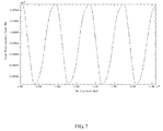
- FIG. 7 shows a torque curve of the single phase synchronous AC motor 10 of the above embodiment during rotation, where the horizontal axis represents the rotation angle with the unit being degree, and the vertical axis represents the torque with the unit being Nm.
- the torque curve of the motor is smooth, which reduces or avoids the startup dead point and hence improves the reliability of the motor startup.
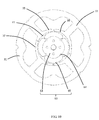
- the stator core of the single phase synchronous AC motor includes a plurality of stator core parts 300 joined along a circumferential direction of the stator.
- Each stator core part 300 includes an arcuate yoke segment 300b, one tooth body 33 extending from the arcuate yoke segment 300b, and a pole shoe 35 extending from a radial distal end of the tooth body 33 to two circumferential sides of the tooth body 33.
- each stator core part 300 includes a single tooth body 33 and one corresponding pole shoe 35. It should be understood that, each stator core part 300 may also include more than one tooth body 33 and corresponding pole shoes 35.
- a recess-protrusion engagement structure is formed at a joining area between the arcuate yoke segments 300b of two adjacent stator core parts 300.
- two ends of the arcuate yoke segment 300b of each stator core part 300 for being connected to form the outer ring portion may be provided with an engagement recess 34 and an engagement protrusion 32, respectively.
- the engagement recess 34 and the engagement protrusion 32 together form the recess-protrusion engagement structure.
- each stator core part 300 engages with the engagement recess 34 of one adjacent stator core part 300, and the engagement protrusion 34 of each stator core part 300 engages with the engagement protrusion 32 of an adjacent stator core part 300.
- the slot 37 between the adjacent pole shoes can have a very small width.
- the width of the slot refers to the distance between the two adjacent pole shoes.
- plane surfaces are formed at the joining areas of the arcuate yoke segments of the adjacent stator core parts 300 of the single phase synchronous AC motor of this embodiment.
- the joining areas of the arcuate yoke segments can be connected by soldering.
- the pole shoe 35 between each two adjacent tooth bodies 33 of the single phase synchronous AC motor likewise forms a positioning slot 38.
- the positioning slot 38 of this embodiment is disposed between the outer circumferential surface and the inner circumferential surface of the pole shoe 35 and, preferably, disposed close to the inner circumferential surface of the pole shoe 35.
- the rotor 60 includes a plurality of permanent magnetic poles 65 arranged along a circumferential direction of the rotor 60.
- An outer circumferential surface of each permanent magnetic pole 65 is an arc surface, such that the permanent magnetic pole 65 and the inner circumferential surface of the pole shoe 35 form a symmetrical uneven air gap 41 therebetween.
- the symmetrical uneven air gap 41 has a maximum thickness that is at least 1.5 times of its minimum thickness.
- Each permanent magnetic pole 65 is formed by a single permanent magnet member.
- the permanent magnet member is mounted to an outer circumferential surface of the rotor core 63.
- the outer circumferential surface of the rotor core 63 defines a plurality of axially extending grooves 64.
- Each groove 64 is located at a junction between two permanent magnetic poles 65 to reduce magnetic leakage.
- the thickness of the permanent magnet member of this embodiment is uniform, and the outer circumferential surface of the rotor core 63 matches with the permanent magnet member in shape. That is, the outer circumferential surface of the rotor core 63 and the inner circumferential surface of the pole shoes 35 are no longer located on concentric circles in the axial plan view. As such, the outer surfaces of the permanent magnetic poles 65 and the inner circumferential surfaces of the pole shoes 35 can still form the symmetrical uneven air gap 41 therebetwen because the outer surface of the permanent magnetic pole 65 is still an arc surface.
- all the permanent magnetic poles 65 may be formed by a single permanent magnet member.
- each slot 37 between every two adjacent pole shoes 35 has a uniform circumferential width.
- each slot 37 may also have a non-uniform circumferential width.
- the slot 37 may be trumpet-shaped with a smaller inside and a larger outside.
- the width of the slot 37 refers to a minimum width of the slot 37 in this disclosure.
- the slot 37 extends along a radial direction of the motor.
- the slot 37 may also extend in a direction deviating from the radial direction of the motor, which can reduce the induction potential of the motor.
- the slots 37 are formed between the adjacent pole shoes 35, and the width of each slot 37 is greater than zero and less than or equal to four times of the minimum thickness of the air gap 41, which can reduce sudden change of the magnetic reluctance caused by a slot opening, thereby reducing the cogging torque of the motor.
- the outer surface of the permanent magnetic pole is configured to be an arc surface, such that the thickness of the air gap 41 progressively increases from a center of the permanent magnetic pole to two circumferential sides of the permanent magnetic pole, thus forming the symmetrical uneven air gap.
- the startup angle and the cogging torque needed during startup of the exemplified single phase synchronous AC motor can be easily adjusted according to design requirements, thus ensuring the reliability of the motor startup.
- the motor startup angle can be easily adjusted by adjusting the position of the positioning slot of the pole shoe.
- the startup angle Q is greater than 45 degrees electric angle and less than 135 degrees electric angle
- the motor rotor can achieve bidirectional startup.
- the cogging torque prior to the startup of the motor can be adjusted by adjusting the shape, size and depth of the positioning slots of the pole shoes.
- the stator core is of a split-type structure, such that the winding process can be performed by using a double-flyer winding machine prior to the assembly of the tooth bodies and the outer ring portion, which increases the winding efficiency.
- FIG. 11 illustrates a schematic circuit diagram of a driving circuit of the single phase synchronous AC motor 10 of the refrigeration apparatus according to one embodiment of the present invention.
- the winding 39 of the stator of the motor and an integrated circuit 70 are connected in series between two terminals of an AC power source 80.
- the driving circuit of the motor 10 is integrated in the integrated circuit 70.
- the driving circuit can drive the motor to start along a fixed direction each time the motor is energized.
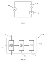
- FIG. 12 illustrates an implementation way of the integrated circuit 70.
- the integrated circuit 70 includes a housing 71, two pins 73 extending out of the housing 71, and a driving circuit packaged in the housing 71.
- the driving circuit is disposed on a semiconductor substrate, including a detecting circuit 75 for detecting a polarity of the rotor magnetic field of the motor, a controllable bidirectional AC switch 77 connected between the two pins 73, and a switch control circuit 79.
- the switch control circuit 79 is configured to control the controllable bidirectional AC switch 77 to be switched between turn-on and turn-off states according to a predetermined manner based on the rotor magnetic field polarity detected by the detecting circuit 75.
- the switch control circuit 79 is configured to control the controllable bidirectional AC switch 77 to turn on only when the AC power source 80 operates in a positive half cycle and the detecting circuit 75 detects a first polarity of the rotor magnetic field, or when the AC power source 80 operates in a negative half cycle and the detecting circuit 75 detects a second polarity of the rotor magnetic field, the second polarity being opposite to the first polarity.
- This configuration can make the winding 39 of the stator drive the rotor to rotate along a fixed direction during the motor startup.
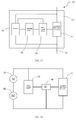
- FIG. 13 illustrates another implementation way of the integrated circuit 70, which differs from FIG. 12 main in that: the integrated circuit of FIG. 13 further includes a rectifier 74 which is connected between the two pins 73 in parallel with the controllable bidirectional AC switch 77, for producing a direct current for the detecting circuit 75.
- the detecting circuit 75 is preferably a magnetic sensor (also referred to as position sensor), and the integrated circuit is mounted adjacent to the rotor such that the magnetic sensor can sense the change of the rotor magnetic field. It should be understood that, in some other embodiments, the detecting circuit 75 may also not include the magnetic sensor. Rather, the detecting circuit 75 detects the change of the rotor magnetic field by other means.
- the driving circuit of the motor is packaged in the integrated circuit, which can reduce cost of the circuit and improve the reliability of the circuit.
- the motor may not use a printed circuit board. Rather, the integrated circuit is simply fixed to a suitable location and then connected the winding of the motor and power source through wires.
- the stator winding 39 and the AC power source 80 are connected in series between the two pins 73.
- the AC power source 80 is preferably a city AC power source with a fixed frequency such as 50 Hz or 60 Hz, a voltage of, for example, 110V, 220V or 230V, and an input power of 6 to 20W.
- the controllable bidirectional AC switch 77 is connected between the two pins 73, in parallel with the series-connected stator winding 39 and AC power 80.
- the controllable bidirectional AC switch 77 is preferably a triode AC switch (TRIAC) having two anodes connected to the two pins 73, respectively.
- TRIAC triode AC switch
- controllable bidirectional AC switch 77 may also be implemented by two unidirectional thyristors reversely connected in parallel that are controlled by a corresponding control circuit according to a predetermined manner.
- the rectifier 74 is connected between the two pins 73, in parallel with the controllable bidirectional AC switch 77.
- the rectifier 74 converts the AC power between the two pins 73 into a low voltage DC power.
- the detecting circuit 75 may be powered by the low voltage DC power outputted from the rectifier 74, for detecting the position of the magnetic poles of the permanent magnet rotor 50 of the single phase synchronous AC motor 10 and outputting corresponding signals.
- the switch control circuit 79 is connected with the rectifier 74, the detecting circuit 75 and the controllable bidirectional AC switch 77, and is configured to control the controllable bidirectional AC switch 77 to be switched between turn-on and turn-off states in a predetermined manner based on the rotor magnetic pole position information detected by the detecting circuit 75 and polarity information of the AC power source 80 obtained from the rectifier 74, such that the stator winding 39 drives the rotor 50 to rotate only along the above described fixed startup direction during the motor startup.
- the controllable bidirectional AC switch 82 when the controllable bidirectional AC switch 82 is turned on, the two pins 73 are short-circuited, and the rectifier 74 does not consume power because no electrical current flows therethrough, such that the power utilization efficiency can be greatly enhanced.
- an input power the AC power source 80 provides to the motor having a voltage of 120V, a frequency of 60 Hz and an input power of 14.2W, and the rotor of the motor rotates at a constant 1800RPM speed in a steady state.
- the motor has an efficiency of 50% to 80%.
- FIG. 14 illustrates a schematic circuit diagram of a driving circuit of the single phase synchronous AC motor 10 of the refrigeration apparatus according to another embodiment of the present invention.
- the winding 39 of the stator of the motor and an integrated circuit 70 are connected in series between two terminals of an AC power source 80.
- the driving circuit of the motor 10 is integrated in the integrated circuit 70.
- the driving circuit can drive the motor to start along a fixed direction each time the motor is energized.
- the driving circuit of the motor is packaged in the integrated circuit, which can reduce cost of the circuit and improve the reliability of the circuit.
- all or part of the rectifier, detecting circuit, switch control circuit and controllable bidirectional AC switch are optionally integrated in the integrated circuit.
- the detecting circuit, the switch control circuit and the controllable bidirectional AC switch may be integrated in the integrated circuit, while the rectifier is disposed outside the integrated circuit.
- a voltage reduction circuit 76 and the controllable bidirectional AC switch 77 are disposed outside the integrated circuit 70, while the rectifier 74 (which may only include a rectifier bridge but does not include a voltage reduction resistor or another voltage reduction element), the detecting circuit 75 and the switch control circuit 79 are integrated in the integrated circuit 70.
- the low power elements are integrated in the integrated circuit, and high power elements such as the voltage reduction circuit 76 and the controllable bidirectional AC switch 77 are disposed outside the integrated circuit 70.
- FIG. 16 it is also possible to integrate the voltage reduction circuit 76 into the integrated circuit 79, with the controllable bidirectional AC switch 77 disposed outside the integrated circuit 70.
Landscapes
- Engineering & Computer Science (AREA)
- Power Engineering (AREA)
- Physics & Mathematics (AREA)
- Mechanical Engineering (AREA)
- Thermal Sciences (AREA)
- General Engineering & Computer Science (AREA)
- Iron Core Of Rotating Electric Machines (AREA)
- Permanent Magnet Type Synchronous Machine (AREA)
- Permanent Field Magnets Of Synchronous Machinery (AREA)
- Motor Or Generator Cooling System (AREA)
- Synchronous Machinery (AREA)
- Chemical & Material Sciences (AREA)
- Combustion & Propulsion (AREA)
- Microelectronics & Electronic Packaging (AREA)
- Control Of Motors That Do Not Use Commutators (AREA)
Applications Claiming Priority (3)
| Application Number | Priority Date | Filing Date | Title |
|---|---|---|---|
| PCT/CN2015/086422 WO2016019921A1 (fr) | 2014-08-08 | 2015-08-07 | Ensemble moteur et circuit intégré pour l'attaque du moteur |
| CN201510543842 | 2015-08-28 | ||
| CN201610390208.8A CN106451831A (zh) | 2015-08-07 | 2016-06-03 | 制冷设备 |
Publications (1)
| Publication Number | Publication Date |
|---|---|
| EP3128659A1 true EP3128659A1 (fr) | 2017-02-08 |
Family
ID=57140325
Family Applications (1)
| Application Number | Title | Priority Date | Filing Date |
|---|---|---|---|
| EP16181410.8A Withdrawn EP3128659A1 (fr) | 2015-08-07 | 2016-07-27 | Appareil de réfrigération |
Country Status (6)
| Country | Link |
|---|---|
| EP (1) | EP3128659A1 (fr) |
| JP (2) | JP2017079581A (fr) |
| KR (1) | KR20170017771A (fr) |
| BR (1) | BR102016017910A2 (fr) |
| DE (1) | DE202016104036U1 (fr) |
| TW (1) | TWM542125U (fr) |
Cited By (2)
| Publication number | Priority date | Publication date | Assignee | Title |
|---|---|---|---|---|
| IT201700024501A1 (it) * | 2017-03-06 | 2018-09-06 | Elica Spa | Motore per ventilatore e ventilatore |
| EP3780341A4 (fr) * | 2018-03-27 | 2021-12-29 | Mitsuba Corporation | Moteur électrique |
Families Citing this family (2)
| Publication number | Priority date | Publication date | Assignee | Title |
|---|---|---|---|---|
| DE102017208280A1 (de) * | 2017-05-17 | 2018-11-22 | BSH Hausgeräte GmbH | Elektrischer Antriebsmotor mit verringerter Geräuschentwicklung sowie diesen enthaltendes Haushaltsgerät |
| CN113364155B (zh) * | 2020-03-05 | 2025-08-26 | 广东威灵电机制造有限公司 | 单相无刷直流电机和电器设备 |
Citations (8)
| Publication number | Priority date | Publication date | Assignee | Title |
|---|---|---|---|---|
| EP0688091A1 (fr) * | 1994-05-04 | 1995-12-20 | Emerson Electric Co. | Alimentation en courant électrique à grande puissance pour un moteur à aimants permanents sans balai |
| EP1014541A1 (fr) * | 1997-09-08 | 2000-06-28 | Matsushita Electric Industrial Co., Ltd. | Moteur synchrone a aimant permanent |
| US20050023923A1 (en) * | 2003-07-30 | 2005-02-03 | Ming-Tsung Chu | Rotor structure of line-start permanent magnet synchronous motor |
| US20110156610A1 (en) * | 2009-12-30 | 2011-06-30 | Leviton Manufacturing Co., Inc. | Phase control with adaptive parameters |
| EP2410653A1 (fr) * | 2010-07-23 | 2012-01-25 | Askoll Holding S.r.l. | Dispositif de commande d'un moteur synchrone avec rotor à aimants permanents |
| US20130057104A1 (en) * | 2011-09-02 | 2013-03-07 | Steven Stretz | Permanent magnet motors and methods of assembling the same |
| US20130088114A1 (en) * | 2011-10-07 | 2013-04-11 | Minebea Co., Ltd. | Inner rotor-type permanent magnet motor |
| US20150042194A1 (en) * | 2013-08-09 | 2015-02-12 | Johnson Electric S.A. | Single-phase brushless motor |
-
2016
- 2016-07-25 DE DE202016104036.1U patent/DE202016104036U1/de not_active Expired - Lifetime
- 2016-07-27 EP EP16181410.8A patent/EP3128659A1/fr not_active Withdrawn
- 2016-08-02 BR BR102016017910A patent/BR102016017910A2/pt not_active Application Discontinuation
- 2016-08-03 KR KR1020160098910A patent/KR20170017771A/ko not_active Withdrawn
- 2016-08-06 TW TW105211946U patent/TWM542125U/zh not_active IP Right Cessation
- 2016-08-08 JP JP2016155892A patent/JP2017079581A/ja not_active Abandoned
- 2016-08-08 JP JP2016003864U patent/JP3207072U/ja not_active Expired - Fee Related
Patent Citations (8)
| Publication number | Priority date | Publication date | Assignee | Title |
|---|---|---|---|---|
| EP0688091A1 (fr) * | 1994-05-04 | 1995-12-20 | Emerson Electric Co. | Alimentation en courant électrique à grande puissance pour un moteur à aimants permanents sans balai |
| EP1014541A1 (fr) * | 1997-09-08 | 2000-06-28 | Matsushita Electric Industrial Co., Ltd. | Moteur synchrone a aimant permanent |
| US20050023923A1 (en) * | 2003-07-30 | 2005-02-03 | Ming-Tsung Chu | Rotor structure of line-start permanent magnet synchronous motor |
| US20110156610A1 (en) * | 2009-12-30 | 2011-06-30 | Leviton Manufacturing Co., Inc. | Phase control with adaptive parameters |
| EP2410653A1 (fr) * | 2010-07-23 | 2012-01-25 | Askoll Holding S.r.l. | Dispositif de commande d'un moteur synchrone avec rotor à aimants permanents |
| US20130057104A1 (en) * | 2011-09-02 | 2013-03-07 | Steven Stretz | Permanent magnet motors and methods of assembling the same |
| US20130088114A1 (en) * | 2011-10-07 | 2013-04-11 | Minebea Co., Ltd. | Inner rotor-type permanent magnet motor |
| US20150042194A1 (en) * | 2013-08-09 | 2015-02-12 | Johnson Electric S.A. | Single-phase brushless motor |
Cited By (2)
| Publication number | Priority date | Publication date | Assignee | Title |
|---|---|---|---|---|
| IT201700024501A1 (it) * | 2017-03-06 | 2018-09-06 | Elica Spa | Motore per ventilatore e ventilatore |
| EP3780341A4 (fr) * | 2018-03-27 | 2021-12-29 | Mitsuba Corporation | Moteur électrique |
Also Published As
| Publication number | Publication date |
|---|---|
| BR102016017910A2 (pt) | 2017-02-14 |
| DE202016104036U1 (de) | 2016-10-26 |
| JP2017079581A (ja) | 2017-04-27 |
| JP3207072U (ja) | 2016-10-20 |
| KR20170017771A (ko) | 2017-02-15 |
| TWM542125U (zh) | 2017-05-21 |
Similar Documents
| Publication | Publication Date | Title |
|---|---|---|
| EP3154177B1 (fr) | Dispositif de regulation de debit d'air | |
| US10432073B2 (en) | Medical pump | |
| EP3101788A1 (fr) | Moteur à rotor externe monophasé et appareil électrique comportant celui-ci | |
| US20170229949A1 (en) | Single phase brushless direct current motor | |
| JP2016214070A (ja) | 単相モータ及びこれを有する電気装置 | |
| KR20160137436A (ko) | 단상 브러시리스 모터 및 전기 장치 | |
| EP3062426A1 (fr) | Moteur sans balais monophasé | |
| US20160169232A1 (en) | Pump And Cleaning Apparatus | |
| KR20080082779A (ko) | 모터 | |
| KR20080082780A (ko) | 모터 | |
| US8575871B1 (en) | Modular component electric machine | |
| EP3128659A1 (fr) | Appareil de réfrigération | |
| US20160352204A1 (en) | Refrigeration apparatus | |
| JP2017198195A (ja) | 冷却ファン、及びこれを備える空冷式冷却装置 | |
| CN106451831A (zh) | 制冷设备 | |
| KR20170024744A (ko) | 고효율 직류 전동기 및 그 제어방법 | |
| CN105308849B (zh) | 无刷电机的相位控制电路、无刷电机及无刷电机的相位控制方法 | |
| US20170099929A1 (en) | Hair Dryer | |
| JP2008061485A (ja) | 交流電源で自起動可能な永久磁石型モータ | |
| JP5460807B1 (ja) | 同期電動機 | |
| JP2006238679A (ja) | 永久磁石型単相モータ | |
| US20170229948A1 (en) | Single phase brushless direct current motor | |
| US20180109208A1 (en) | Synchronous motor assembly, pump, and ventilation fan using same | |
| KR101076078B1 (ko) | 출력 가변식 브러쉬리스 직류모터 | |
| KR20080082781A (ko) | 모터 및 이를 포함하는 압축기 |
Legal Events
| Date | Code | Title | Description |
|---|---|---|---|
| PUAI | Public reference made under article 153(3) epc to a published international application that has entered the european phase |
Free format text: ORIGINAL CODE: 0009012 |
|
| AK | Designated contracting states |
Kind code of ref document: A1 Designated state(s): AL AT BE BG CH CY CZ DE DK EE ES FI FR GB GR HR HU IE IS IT LI LT LU LV MC MK MT NL NO PL PT RO RS SE SI SK SM TR |
|
| AX | Request for extension of the european patent |
Extension state: BA ME |
|
| 17P | Request for examination filed |
Effective date: 20170724 |
|
| RBV | Designated contracting states (corrected) |
Designated state(s): AL AT BE BG CH CY CZ DE DK EE ES FI FR GB GR HR HU IE IS IT LI LT LU LV MC MK MT NL NO PL PT RO RS SE SI SK SM TR |
|
| 17Q | First examination report despatched |
Effective date: 20171222 |
|
| RAP1 | Party data changed (applicant data changed or rights of an application transferred) |
Owner name: JOHNSON ELECTRIC INTERNATIONAL AG |
|
| STAA | Information on the status of an ep patent application or granted ep patent |
Free format text: STATUS: THE APPLICATION IS DEEMED TO BE WITHDRAWN |
|
| 18D | Application deemed to be withdrawn |
Effective date: 20191115 |