EP3128681A1 - Interferenzunterdrückungsverstärker - Google Patents
Interferenzunterdrückungsverstärker Download PDFInfo
- Publication number
- EP3128681A1 EP3128681A1 EP14888192.3A EP14888192A EP3128681A1 EP 3128681 A1 EP3128681 A1 EP 3128681A1 EP 14888192 A EP14888192 A EP 14888192A EP 3128681 A1 EP3128681 A1 EP 3128681A1
- Authority
- EP
- European Patent Office
- Prior art keywords
- signal
- interference cancellation
- unit
- gain
- control unit
- Prior art date
- Legal status (The legal status is an assumption and is not a legal conclusion. Google has not performed a legal analysis and makes no representation as to the accuracy of the status listed.)
- Granted
Links
Images


Classifications
-
- H—ELECTRICITY
- H04—ELECTRIC COMMUNICATION TECHNIQUE
- H04B—TRANSMISSION
- H04B7/00—Radio transmission systems, i.e. using radiation field
- H04B7/14—Relay systems
- H04B7/15—Active relay systems
- H04B7/155—Ground-based stations
- H04B7/15564—Relay station antennae loop interference reduction
- H04B7/15585—Relay station antennae loop interference reduction by interference cancellation
-
- H—ELECTRICITY
- H03—ELECTRONIC CIRCUITRY
- H03F—AMPLIFIERS
- H03F1/00—Details of amplifiers with only discharge tubes, only semiconductor devices or only unspecified devices as amplifying elements
- H03F1/32—Modifications of amplifiers to reduce non-linear distortion
- H03F1/3241—Modifications of amplifiers to reduce non-linear distortion using predistortion circuits
- H03F1/3247—Modifications of amplifiers to reduce non-linear distortion using predistortion circuits using feedback acting on predistortion circuits
-
- H—ELECTRICITY
- H03—ELECTRONIC CIRCUITRY
- H03F—AMPLIFIERS
- H03F3/00—Amplifiers with only discharge tubes or only semiconductor devices as amplifying elements
- H03F3/189—High-frequency amplifiers, e.g. radio frequency amplifiers
- H03F3/19—High-frequency amplifiers, e.g. radio frequency amplifiers with semiconductor devices only
-
- H—ELECTRICITY
- H03—ELECTRONIC CIRCUITRY
- H03F—AMPLIFIERS
- H03F3/00—Amplifiers with only discharge tubes or only semiconductor devices as amplifying elements
- H03F3/20—Power amplifiers, e.g. Class B amplifiers, Class C amplifiers
- H03F3/21—Power amplifiers, e.g. Class B amplifiers, Class C amplifiers with semiconductor devices only
-
- H—ELECTRICITY
- H04—ELECTRIC COMMUNICATION TECHNIQUE
- H04B—TRANSMISSION
- H04B17/00—Monitoring; Testing
- H04B17/30—Monitoring; Testing of propagation channels
- H04B17/309—Measuring or estimating channel quality parameters
- H04B17/318—Received signal strength
- H04B17/328—Reference signal received power [RSRP]; Reference signal received quality [RSRQ]
-
- H—ELECTRICITY
- H04—ELECTRIC COMMUNICATION TECHNIQUE
- H04B—TRANSMISSION
- H04B7/00—Radio transmission systems, i.e. using radiation field
- H04B7/14—Relay systems
- H04B7/15—Active relay systems
- H04B7/155—Ground-based stations
- H04B7/15564—Relay station antennae loop interference reduction
- H04B7/15578—Relay station antennae loop interference reduction by gain adjustment
-
- H—ELECTRICITY
- H04—ELECTRIC COMMUNICATION TECHNIQUE
- H04L—TRANSMISSION OF DIGITAL INFORMATION, e.g. TELEGRAPHIC COMMUNICATION
- H04L5/00—Arrangements affording multiple use of the transmission path
- H04L5/003—Arrangements for allocating sub-channels of the transmission path
- H04L5/0048—Allocation of pilot signals, i.e. of signals known to the receiver
Definitions
- the inventive concept relates to an interference cancellation relay device, and particularly, to an interference cancellation relay device having a pre-distortion function.
- a relay device is used for transmitting a signal between a base station and a terminal and extension of a service or improvement of a service quality in a radio signal shadow area.
- a wireless relay device may be provided as one example of the relay device, and the wireless relay device provides a communication service for receiving the signal transmitted from the base station or the terminal through a receiving antenna, amplifying the received signal, and transmitting the amplified signal to the terminal or the base station through a transmitting antenna.
- a degree of isolation at a predetermined level or higher is required between the receiving antenna and the transmitting antenna in order to prevent deterioration in quality of the communication service.
- a research into an interference cancellation relay device has been actively conducted, which can secure the degree of isolation while overcoming the spatial limitation by applying an interference cancellation function to cancel feed-back signals, that is, signals input into the receiving antenna as interference signals through a variety of paths, after the signals are radiated from the transmitting antenna.
- the radio relay device has a power amplifier at a transmitting end to transmit a signal having sufficient power to the terminal or the base station and the deterioration in quality of the communication service is caused due to a non-linear characteristic of the power amplifier.
- a pre-distortion function for improving the non-linear characteristic of the power amplifier in the wireless relay device has been continued and in particular, an attempt for implementing the pre-distortion function even in the interference cancellation relay device has been actively made.
- the inventive concept directs to an interference cancellation relay device in which a pre-distortion function can be stably implemented.
- an interference cancellation relay device comprising: an interference cancellation unit cancelling an interference signal from an input signal and outputting the input signal from which the interference signal is cancelled; a gain control unit controlling a gain of an output signal of the interference cancellation unit; and a pre-distortion unit distorting the output signal of the interference cancellation unit, of which the gain is controlled by the gain control unit.
- the gain control unit may include, a measurement unit detecting a reference signal from the output signal of the interference cancellation unit and measuring an intensity of the reference signal; and a control unit controlling the gain of the output signal of the interference cancellation unit by using the intensity of the reference signal.
- the reference signal may be a signal having a predetermined intensity regardless of fluctuation of a data amount included in the input signal.
- the measurement unit may include, a detection unit detecting the reference signal from the output signal of the interference cancellation unit; and a calculation unit calculating the intensity of the reference signal.
- control unit may include, a comparison unit comparing the intensity of the reference signal with a predetermined reference intensity; and a control unit controlling the gain of the output signal of the interference cancellation unit according to a result of comparing the intensity of the reference signal and the reference intensity.
- an interference cancellation relay device comprising: a first gain control unit controlling a gain of an input signal; a conversion unit digitalizing the input signal of which the gain is controlled by the first gain control unit; an interference cancellation unit cancelling an interference signal from the digitalized input signal and outputting the input signal from which the interference signal is cancelled; a second gain control unit controlling the gain of the output signal of the interference cancellation unit; and a pre-distortion unit distorting the output signal of the interference cancellation unit, of which the gain is controlled by the second gain control unit.
- the second gain control unit may include, a measurement unit detecting a reference signal from the output signal of the interference cancellation unit and measuring an intensity of the reference signal; and a first control unit controlling the gain of the output signal of the interference cancellation unit by using the intensity of the reference signal.
- the reference signal may be a signal having a predetermined intensity regardless of fluctuation of a data amount included in the input signal.
- the first gain control unit may control the gain of the input signal by using the intensity of the reference signal, which is measured by the measurement unit.
- an interference cancellation relay device includes a gain control unit constantly controlling an output signal of an interference cancellation unit and providing the output signal to a pre-distortion unit, and as a result, the interference of signals and the oscillation can be minimized and the pre-distortion unit can stably improve a non-linear characteristic of a power amplifier, thereby improving the quality of a communication service.
- inventive concept may be variously modified and have various embodiments, so that specific embodiments will be illustrated in the drawings and described in the detailed description. However, this does not limit the inventive concept to specific embodiments, and it should be understood that the inventive concept covers all the modifications, equivalents and replacements included within the idea and technical scope of the inventive concept.
- units that processes at least one function or operation and this may be implemented by hardware or software or a combination of hardware and software.
- components are just classified for each main function which each component takes charge of. That is, two or more components to be described below may be provided to be combined into one component or one component may be provided to be separated into two or more for each of more subdivided functions.
- each of the components to be described below may additionally perform some or all functions among functions which other components take charge of in addition to the main function which each component takes charge of and some functions among the main functions which the respective take charge of may be exclusively charged and performed by other components.
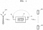
- FIG. 1 is a diagram for describing a relay environment of an interference cancellation relay device 10 according to an embodiment of the inventive concept.
- a donor antenna transceiving a signal with a base station BTS is illustrated as a receiving antenna RX and a service antenna transceiving the signal with a terminal MS is illustrated as a transmitting antenna TX, for convenience of the explanation.
- the interference cancellation relay device 10 includes one receiving antenna RX and one transmitting antenna TX, but is not limited thereto and interference cancellation relay device 10 may include at least two receiving antennas RX and at least two transmitting antennas TX.
- the interference cancellation relay device 10 may amplify a downlink signal of the base station BTS received through the receiving antenna RX and transmit the amplified downlink signal to the terminal MS through the transmitting antenna TX.
- the interference cancellation relay device 10 may be oscillated.
- the interference cancellation relay device 10 includes an interference cancellation unit 300 (see FIG. 2 or 5 ) that may cancel interference signals caused by the signal radiated from the transmitting antenna TX from the downlink signal of the base station BTS.
- the interference cancellation relay device 10 when the interference cancellation relay device 10 amplifies the downlink signal of the base station BTS through the power amplifier (not illustrated) and transmits the amplified downlink signal, the downlink signal of the base station BTS is distorted due to the non-linear characteristic of the power amplifier, and as a result, the quality of a communication service may deteriorate.
- the interference cancellation relay device 10 includes a pre-distortion unit 500 (see FIG. 2 or 5 ) that pre-distorts an input signal into the amplifier based on the non-linear characteristic of the power amplifier, which is measured by detecting an output signal of the power amplifier.
- a general interference cancellation relay device receives the downlink signal of the base station through wirelessly, that is, through the receiving antenna as described above, the general interference cancellation relay device is influenced by the interference signals, and as a result, an input signal into the interference cancellation relay device is rapidly changed.
- the general interference cancellation relay device it is difficult to stably perform the pre-distortion function and it is difficult to secure quality reliability of the communication service.
- the interference cancellation relay device 10 includes a gain control unit 400 (see FIG. 2 or 50 that constantly maintains an output signal gain of the interference cancellation unit to allow the pre-distortion unit to stably operate, thereby securing the reliability of the communication service.
- a gain control unit 400 see FIG. 2 or 50 that constantly maintains an output signal gain of the interference cancellation unit to allow the pre-distortion unit to stably operate, thereby securing the reliability of the communication service.
- the interference cancellation relay device 10 may amplify an uplink signal of the terminal MS, which is received through the transmitting antenna TX and transmit the amplified uplink signal to the base station BTS through the receiving antenna RX.
- signals radiated through the receiving antenna RX are input into the transmitting antenna TX through the wireless environment to form the interference signal, and as a result, as the uplink signal of the terminal MS, which is an original signal input into the transmitting antenna TX and the interference signal are aggregated and amplified, the interference cancellation relay device 10 may be oscillated.
- the interference cancellation relay device 10 may further include an interference cancellation unit, a gain control unit, and a pre-distortion unit in an uplink similarly to the interference cancellation unit, the gain control unit, and the pre-distortion unit in the downlink.
- components which correspond to each other in the downlink and the uplink of the interference cancellation relay device 10 may be implemented as one or implemented separately.
- the gain control unit in the downlink and the gain control unit in the uplink of the interference cancellation relay device 10 may be implemented as one component or implemented as respective distinguished components.
- FIG. 2 is a block diagram schematically illustrating an interference cancellation relay device 10 according to an embodiment of the inventive concept.
- FIG. 2 only components for transmitting the downlink signal of the base station BTS (see FIG. 1 ) to the terminal MS (see FIG. 1 ) in the interference cancellation relay device 10 are illustrated for convenience of the explanation. Since components for transmitting the uplink signal of the terminal MS (see FIG. 1 ) to the base station BTS (see FIG. 1 ) may correspond to the components for transmitting the downlink signal, hereinafter, detailed description of the components for transmitting the uplink signal will be omitted. Further, a reception processing unit 100 and an analog/digital conversion unit 200 and a digital/analog conversion unit 600 and a transmission processing unit 700 are illustrated as respective separate components for convenience of the explanation in FIG. 2 .
- the interference cancellation relay device 10 may include the receiving antenna RX, the reception processing unit 100, the analog/digital conversion unit 200, the interference cancellation unit 300, the gain control unit 400, the pre-distortion unit 500, the digital/analog conversion unit 600, the transmission processing unit 700, and the receiving antenna TX.
- the reception processing unit 100 may receive an input signal provided to the interference cancellation relay device 10 from the base station BTS (see FIG. 1 ) through the receiving antenna RX.
- the input signal may include at least one of the downlink signal of the base station BTS (see FIG. 1 ) and the interference signal based on the signal radiated through the transmitting antenna TX.
- the reception processing unit 100 may be configured to eliminate noise from the input signal and frequency-down-convert the input signal and output the input signal which is frequency-down-converted.
- the reception processing unit 100 may include a filter for selecting a required band in the input signal, a low noise amplifier amplifying the input signal by minimizing the noise in the input signal, and a frequency down converter converting the input signal amplified by the low noise amplifier into a signal in an intermediate frequency band from a signal in a radio frequency (RF) band, and perform signal processing for converting the input signal into a digital signal by the analog/digital conversion unit 200 through the above-described components.
- the frequency down converter may be optionally omitted.
- the reception processing unit 100 may further include a filter for eliminating an image frequency from the input signal between the low noise amplifier and the frequency down converter. Further, the reception processing unit 100 may further include the amplifier for amplifying the input signal converted into the signal in the intermediate frequency band, another frequency down converter for converting the amplified input signal in the intermediate frequency band into a signal in a baseband, and the like.
- the analog/digital conversion unit 200 may receive the input signal signal-processed by the reception processing unit 100.
- the analog/digital conversion unit 200 may convert the input signal signal-processed by the reception processing unit 100 into the digital signal.
- the interference cancellation unit 300 may receive the input signal digitalized from the analog/digital conversion unit 200.
- the interference cancellation unit 300 may cancel the interference signal from the digitalized input signal and output the digitalized input signal from which the interference signal is cancelled.
- the interference cancellation unit 300 may model an estimation interference signal corresponding to the interference signal based on the digitalized input signal input into the interference cancellation unit 300 or the output signal of the interference cancellation unit 200, which is fed back, and cancel the interference signal from the digitalized input by using the modeled estimation interference signal and output the downlink signal which is the original signal.
- the gain control unit 400 may control a gain of the output signal of the interference cancellation unit 300, that is, the digitalized input signal from which the interference signal is canceled.
- the gain control unit 400 may constantly maintain the gain of the output signal of the interference cancellation unit 300 to correspond to a predetermined level. Hereinafter, this will be described in more detail with reference to FIGS. 3 and 4 .
- the pre-distortion unit 500 may receive the output signal of the interference cancellation unit 300, of which the gain is controlled by the gain control unit 400.
- the pre-distortion unit 500 may distort and output the output signal of the interference cancellation unit 300, of which the gain is controlled by the gain control unit 400 based on the non-linear characteristic of a power amplifier (not illustrated) included in the transmission processing unit 700.
- the pre-distortion unit 500 may receive the output signal of the power amplifier, measure the non-linear characteristic of the power amplifier from the output signal of the power amplifier, and distort and output the output signal of the interference cancellation unit 300, of which the gain is controlled so as to have non-linearity contrary to the measured non-linear characteristic of the power amplifier.
- the digital/analog conversion unit 600 may receive the output signal of the interference cancellation unit 300, which is distorted by the pre-distortion unit 500.
- the digital/analog conversion unit 600 may convert the output signal of the interference cancellation unit 300 into the analog signal by the pre-distortion unit 500.
- the transmission processing unit 700 may be configured to frequency-up-convert, amplify, and output the analog signal.
- the transmission processing unit 700 may include a frequency up converter up-converting the analog signal into the signal in the radio frequency band, a power amplifier amplifying and outputting the signal frequency-up-converted by the frequency up converter, and a filter for selecting a band required in the amplified signal, and perform signal processing for transmitting the analog signal to the terminal MS (see FIG. 1 ) through the transmitting antenna TX by using the aforementioned components.
- the frequency up converter may be optionally omitted.
- the transmission processing unit 700 may further include an isolator for protecting the power amplifier, and the like at the rear end of the power amplifier.
- the interference cancellation relay device 10 includes the gain control unit 400 between the interference cancellation unit 300 and the pre-distortion unit 500 to constantly maintain the gain of the signal input into the pre-distortion unit 500, and thereby preventing distortion of a transmission signal while minimizing interference and oscillation of the signal by the interference cancellation unit 300, and as a result, the quality of the communication service may be enhanced.
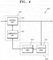
- FIGS. 3 and 4 are diagrams for, in detail, describing some components of the interference cancellation relay device 10 of FIG. 2 .
- FIG. 3 is a diagram illustrating, in more detail, a gain control unit 400 and
- FIG. 4 is a diagram illustrating one implementation example of a measurement unit 420 and a control unit 440 in the gain control unit 400.
- the gain control unit 400 may include the measurement unit 420 and the control unit 440.
- the measurement unit 420 may detect a reference signal from the output signal of the interference cancellation unit 300 that is the digitalized input signal, which is corresponded to the downlink signal equivalent to the original signal according as the interference signal is cancelled therefrom, and measure the intensity of the reference signal.
- the reference signal may be a signal having a predetermined intensity regardless of fluctuation of a data amount included in the downlink signal provided from the base station BTS (see FIG. 1 ) among input signals into the interference cancellation relay device 10.
- LTE long term evolution
- the reference signal may be a primary synchronization signal (PSS) or a secondary synchronization signal (SSS) which is a signal distinguished from a data signal and is a synchronization signal.
- PSS primary synchronization signal
- SSS secondary synchronization signal
- the reference signal may be a pilot signal which is a synchronization signal.
- the measurement unit 420 may include a detection unit 422 detecting the reference signal from the output signal of the interference cancellation unit 300 and a calculation unit 424 calculating the intensity of the detected reference signal.
- the detection unit 422 may filter the primary synchronization signal which is present at a center frequency in the output signal of the interference cancellation unit 300 and the calculation unit 424 may be configured to calculate the intensity of the filtered primary synchronization signal.
- the control unit 440 may control the gain of the output signal of the interference cancellation unit 300 by using the intensity of the reference signal measured by the measurement unit 420. For example, the control unit 440 compares the intensity of the reference signal with a predetermined reference intensity and control the gain of the output signal of the interference cancellation unit 300 according to a result of the comparison.
- the predetermined reference intensity may correspond to a level of the gain to allow the pre-distortion unit 500 to stably operate.
- the reference intensity may be provided from a processor (not illustrated) of the interference cancellation relay device 10 and updated adaptively to a change of the communication service, and the like.
- the control unit 440 may include a comparison unit 442 comparing the intensity of the reference signal with the predetermined reference intensity and a control unit 444 controlling the gain of the output signal of the interference cancellation unit 300 according to a result of the comparison. For example, according to the comparison result by the comparison unit 442, when the intensity of the reference signal is larger than the reference intensity, the control unit 444 may decrease the gain of the output signal of the interference cancellation unit 300, when the intensity of the reference signal is smaller than the reference intensity, the control unit 444 may increase the gain of the output signal of the interference cancellation unit 300, and when intensity of the reference signal is the same as the reference intensity, the control unit 444 may be configured to maintain the gain of the output signal of the interference cancellation unit 300.
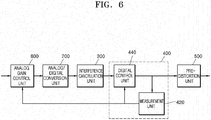
- FIG. 5 is a block diagram schematically illustrating an interference cancellation relay device 10' according to another embodiment of the inventive concept.
- the interference cancellation relay device 10' illustrated in FIG. 5 as a modified example of the interference cancellation relay device 10 illustrated in FIG. 2 further includes an analog gain control unit 800 between the reception processing unit 100 and the analog/digital conversion unit 200 unlike the interference cancellation relay device 10 of FIG. 2 .
- FIG. 5 duplicated description with FIGS. 2 to 4 will be omitted and a different from FIGS. 2 to 4 will be primarily described.
- the interference cancellation relay device 10' may include the receiving antenna RX, the reception processing unit 100, the analog gain control unit 800, the analog/digital conversion unit 200, the interference cancellation unit 300, the gain control unit (hereinafter, referred to as a digital gain control unit for convenience of the explanation, 400), the pre-distortion unit 500, the digital/analog conversion unit 600, the transmission processing unit 700, and the receiving antenna TX.
- the reception processing unit 100 may receive the input signal provided to the interference cancellation relay device 10 from the base station BTS (see FIG. 1 ) through the receiving antenna RX and may be configured to eliminate the noise from the input signal and down-convert the frequency of the input signal and output the input signal.
- the analog gain control unit 800 may control the gain of the input signal signal-processed by the reception processing unit 100.
- the analog gain control unit 800 may constantly maintain the gain of the input signal signal-processed by the reception processing unit 100 to correspond to a predetermined level.
- analog gain control unit 800 is a component apart from the reception processing unit 100 for convenience of the explanation, but the inventive concept is not limited thereto.
- the analog gain control unit 800 may be included in the reception processing unit 100, of course.
- the analog/digital conversion unit 200 may receive the input signal of which the gain is controlled by the analog gain control unit 800 and convert the received input signal into the digital signal.
- the interference cancellation unit 300 may receive the input signal digitalized from the analog/digital conversion unit 200 and cancel the interference signal from the digitalized input signal and output the input signal from which the interference signal is cancelled.
- the digital gain control unit 400 may control the gain of the output signal of the interference cancellation unit 300, that is, the digitalized input signal from which the interference signal is cancelled.
- the gain control unit 400 may constantly maintain the gain of the output signal of the interference cancellation unit 300 to correspond to a predetermined level.
- the pre-distortion unit 500 may receive the output signal of the interference cancellation unit 300 of which the gain is controlled by the digital gain control unit 400 and distort and output the output signal of the interference cancellation unit 300 based on the non-linear characteristic of the power amplifier (not illustrated) included in the transmission processing unit 700.
- the digital/analog conversion unit 600 may receive the output signal of the interference cancellation unit 300, which is distorted by the pre-distortion unit 500 and convert the output signal into the analog signal.
- the transmission processing unit 700 may be configured to frequency-up-convert and amplify the analog signal and transmit the corresponding signal to the terminal MS (see FIG. 1 ) through the transmitting antenna TX.
- the interference cancellation relay device 10' includes the gain control unit 400 between the interference cancellation unit 300 and the pre-distortion unit 500 to constantly maintain the gain of the signal input into the pre-distortion unit 500 and constantly maintain the gain of the signal input into the interference cancellation unit 300 after digitally converted, thereby preventing oscillation and distortion of transmission signals, and as a result, the quality of the communication service may be improved.
- FIGS. 6 and 7 are diagrams for, in detail, describing some components of the interference cancellation relay device 10' of FIG. 5 .
- FIG. 6 is a diagram illustrating, in more detail, a digital gain control unit 400 and an analog gain control unit 800
- FIG. 7 is a diagram illustrating one implementation example of a connection between a measurement unit 420 and a control unit 440 and between an analog gain control unit 800 and a measurement unit 420 in the digital gain control unit 400.
- duplicated description with FIGS. 2 to 4 will be omitted and a different from FIGS. 2 to 4 will be primarily described.
- the control unit 440 of the digital gain control unit 400 may constantly maintain the gain of the output signal of the interference cancellation unit 300 by using the intensity of the reference signal, which is measured by the measurement unit 420, for example, an intensity of a signal having a predetermined intensity regardless of fluctuation of the data mount included in the downlink signal provided from the base station BTS (see FIG. 1 ) among input signals into the interference cancellation relay device 10'.
- the analog gain control unit 800 may constantly maintain the gain of the input signal digitalized through the analog/digital conversion unit 200 and input into the interference cancellation unit 300 by using the intensity of the reference signal, which is measured by the measurement unit 420 of the digital gain control unit 400.
- the analog gain control unit 800 may be configured similarly to the control unit 440 of the digital gain control unit 400.
Landscapes
- Engineering & Computer Science (AREA)
- Signal Processing (AREA)
- Computer Networks & Wireless Communication (AREA)
- Quality & Reliability (AREA)
- Power Engineering (AREA)
- Physics & Mathematics (AREA)
- Electromagnetism (AREA)
- Nonlinear Science (AREA)
- Radio Relay Systems (AREA)
- Mobile Radio Communication Systems (AREA)
Applications Claiming Priority (2)
| Application Number | Priority Date | Filing Date | Title |
|---|---|---|---|
| KR1020140037347A KR101791633B1 (ko) | 2014-03-29 | 2014-03-29 | 간섭 제거 중계 장치 |
| PCT/KR2014/005900 WO2015152465A1 (ko) | 2014-03-29 | 2014-07-02 | 간섭 제거 중계 장치 |
Publications (3)
| Publication Number | Publication Date |
|---|---|
| EP3128681A1 true EP3128681A1 (de) | 2017-02-08 |
| EP3128681A4 EP3128681A4 (de) | 2017-11-01 |
| EP3128681B1 EP3128681B1 (de) | 2023-08-30 |
Family
ID=54240761
Family Applications (1)
| Application Number | Title | Priority Date | Filing Date |
|---|---|---|---|
| EP14888192.3A Active EP3128681B1 (de) | 2014-03-29 | 2014-07-02 | Interferenzunterdrückungsverstärker |
Country Status (5)
| Country | Link |
|---|---|
| US (2) | US9941951B2 (de) |
| EP (1) | EP3128681B1 (de) |
| KR (1) | KR101791633B1 (de) |
| CN (1) | CN106134097B (de) |
| WO (1) | WO2015152465A1 (de) |
Families Citing this family (9)
| Publication number | Priority date | Publication date | Assignee | Title |
|---|---|---|---|---|
| WO2013173252A1 (en) | 2012-05-13 | 2013-11-21 | Invention Mine Llc | Full duplex wireless transmission with channel phase-based encryption |
| US10177896B2 (en) | 2013-05-13 | 2019-01-08 | Amir Keyvan Khandani | Methods for training of full-duplex wireless systems |
| KR101791633B1 (ko) * | 2014-03-29 | 2017-10-30 | 주식회사 쏠리드 | 간섭 제거 중계 장치 |
| KR101852997B1 (ko) * | 2014-12-30 | 2018-04-30 | 주식회사 쏠리드 | 간섭 제거 중계 장치 |
| KR101825416B1 (ko) * | 2014-12-30 | 2018-03-22 | 주식회사 쏠리드 | 간섭 제거 중계 장치 |
| KR102159022B1 (ko) * | 2016-02-18 | 2020-09-23 | 주식회사 쏠리드 | 간섭제거 중계장치 및 그 동작 방법 |
| CN107332591B (zh) * | 2016-04-29 | 2021-01-05 | 北京紫光展锐通信技术有限公司 | 中继器及其回波干扰消除方法、装置 |
| US10700766B2 (en) * | 2017-04-19 | 2020-06-30 | Amir Keyvan Khandani | Noise cancelling amplify-and-forward (in-band) relay with self-interference cancellation |
| KR102153434B1 (ko) * | 2019-07-09 | 2020-09-21 | 에스케이텔레콤 주식회사 | 동기 신호를 이용한 무선중계기의 이득을 설정하기 위한 장치 및 이를 위한 방법 |
Family Cites Families (38)
| Publication number | Priority date | Publication date | Assignee | Title |
|---|---|---|---|---|
| JP4020458B2 (ja) * | 1997-06-19 | 2007-12-12 | 三菱電機株式会社 | 無線通信システム、データ送信機及びデータ受信機 |
| US7072632B2 (en) * | 2003-10-10 | 2006-07-04 | Vixs, Inc. | Fast signal detection process |
| EP1992084A4 (de) * | 2006-03-07 | 2012-03-28 | Airpoint Co Ltd | Adaptives vorwärtsfehler-korrekturgerät und verfahren dafür sowie tdd-funkverstärkungsvorrichtung damit |
| KR20070113887A (ko) * | 2006-05-26 | 2007-11-29 | 주식회사 케이티 | 무선통신 중계기에서 수신 전력을 이용한 이득 설정 장치및 그 방법 |
| KR100844828B1 (ko) * | 2006-11-24 | 2008-07-08 | 주식회사알에프윈도우 | 안테나를 내장한 궤환 간섭신호 제거 무선중계장치 |
| KR100879335B1 (ko) * | 2007-02-23 | 2009-01-19 | (주)에어포인트 | 전치 왜곡 기능을 구비한 귀환간섭신호 제거 중계 시스템및 그 방법 |
| JP5134016B2 (ja) * | 2007-03-02 | 2013-01-30 | クゥアルコム・インコーポレイテッド | 信号品質を向上させるためのオンライン中継器と連携した適応アンテナアレイの使用 |
| KR100879334B1 (ko) * | 2007-03-06 | 2009-01-19 | (주)에어포인트 | 초소형 일체형 간섭 제거 무선중계 장치 및 그 방법 |
| CN101150515B (zh) * | 2007-11-15 | 2011-06-22 | 复旦大学 | 一种基于双时隙交织迭代的宽带再生多跳中继通信方法 |
| WO2009128674A2 (en) * | 2008-04-18 | 2009-10-22 | Darbs Co.,Ltd | Co-channel feedback signal cancelling regenerative repeater of advanced television system committee |
| KR20090111031A (ko) * | 2008-04-21 | 2009-10-26 | 주식회사알에프윈도우 | 적응적으로 자동 이득 조절이 가능한 간섭제거모듈, 무선중계기, 및 그 방법 |
| KR101498286B1 (ko) * | 2008-05-23 | 2015-03-03 | 삼성전자주식회사 | 무선 통신 시스템에서의 자동 이득 제어 장치 및 방법 |
| WO2010019017A2 (ko) * | 2008-08-14 | 2010-02-18 | 한국전자통신연구원 | Ofdm 기반 무선통신 시스템에서 동일 주파수 릴레이 및 리피터의 자기간섭 제거 방법 및 그 장치 |
| US8385820B2 (en) * | 2009-01-12 | 2013-02-26 | Telefonaktiebolaget Lm Ericsson (Publ) | Systems and method for canceling feedback interference |
| US8452230B2 (en) * | 2009-05-11 | 2013-05-28 | Qualcomm Incorporated | Multi-metric gain control for wireless repeater |
| US8611227B2 (en) * | 2009-05-11 | 2013-12-17 | Qualcomm Incorporated | Channel estimate pruning in presence of large signal dynamics in an interference cancellation repeater |
| US9049065B2 (en) * | 2009-05-11 | 2015-06-02 | Qualcomm Incorporated | Removal of ICI/ISI errors in frequency domain channel estimation for wireless repeaters |
| US8358969B2 (en) * | 2009-05-11 | 2013-01-22 | Qualcomm Incorporated | Feedback delay control in an echo cancellation repeater |
| US20110116531A1 (en) * | 2009-05-11 | 2011-05-19 | Qualcomm Incorporated | Removal of multiplicative errors in frequency domain channel estimation for wireless repeaters |
| US8542623B2 (en) * | 2010-01-13 | 2013-09-24 | Qualcomm Incorporated | Use of RF reference in a digital baseband interference cancellation repeater |
| JP2011166529A (ja) * | 2010-02-10 | 2011-08-25 | Toshiba Corp | 無線中継装置 |
| US8548375B2 (en) * | 2010-03-12 | 2013-10-01 | Qualcomm Incorporated | Gain control metric computation in a wireless repeater |
| US8773966B1 (en) * | 2010-05-07 | 2014-07-08 | Marvell International Ltd. | Signal power measurement and automatic gain control in orthogonal frequency division multiple access systems |
| US8630211B2 (en) * | 2010-06-30 | 2014-01-14 | Qualcomm Incorporated | Hybrid radio architecture for repeaters using RF cancellation reference |
| US9882628B2 (en) * | 2010-10-29 | 2018-01-30 | Telefonaktiebolaget Lm Ericsson (Publ) | Self-interference suppression control for a relay node |
| US8503926B2 (en) * | 2010-11-05 | 2013-08-06 | Qualcomm Incorporated | IQ imbalance compensation in interference cancellation repeater using a zero-IF radio architecture |
| US8553610B2 (en) * | 2011-05-12 | 2013-10-08 | Qualcomm Incorporated | Interference cancellation repeater incorporating a non-linear element |
| US8687540B2 (en) * | 2011-06-07 | 2014-04-01 | Qualcomm Incorporated | Echo cancellation repeater using an inserted pilot with gain-based power level control scheme |
| US20130034128A1 (en) * | 2011-08-05 | 2013-02-07 | Qualcomm Incorporated | Echo cancellation repeater operation in the absence of an input signal |
| US8937874B2 (en) * | 2011-09-23 | 2015-01-20 | Qualcomm Incorporated | Adjusting repeater gains based upon received downlink power level |
| US20130078907A1 (en) * | 2011-09-23 | 2013-03-28 | Qualcomm Incorporated | Per carrier gain control in a multi-carrier repeater |
| US20130077556A1 (en) * | 2011-09-23 | 2013-03-28 | Qualcomm Incorporated | Setting gains in an interference cancellation repeater based on path loss |
| US8774708B2 (en) * | 2011-11-10 | 2014-07-08 | Qualcomm Incorporated | Estimation of repeater loop delay for repeater gain control |
| US20130143483A1 (en) * | 2011-12-06 | 2013-06-06 | Qualcomm Incorporated | Maintaining repeater stability in a multi-repeater scenario |
| US8638835B2 (en) * | 2011-12-06 | 2014-01-28 | Qualcomm Incorporated | Wireless repeater implementing multi-parameter gain management |
| US8837559B2 (en) * | 2012-08-16 | 2014-09-16 | Andrew Wireless Systems Gmbh | Reducing distortion in repeaters for OFDM signals |
| CN103078710A (zh) * | 2013-01-04 | 2013-05-01 | 北京邮电大学 | 多组多用户双向中继网络中一种对抗干扰的方法 |
| KR101791633B1 (ko) * | 2014-03-29 | 2017-10-30 | 주식회사 쏠리드 | 간섭 제거 중계 장치 |
-
2014
- 2014-03-29 KR KR1020140037347A patent/KR101791633B1/ko active Active
- 2014-07-02 CN CN201480077598.2A patent/CN106134097B/zh active Active
- 2014-07-02 US US15/117,926 patent/US9941951B2/en active Active
- 2014-07-02 WO PCT/KR2014/005900 patent/WO2015152465A1/ko not_active Ceased
- 2014-07-02 EP EP14888192.3A patent/EP3128681B1/de active Active
-
2018
- 2018-03-01 US US15/909,481 patent/US10686517B2/en active Active
Also Published As
| Publication number | Publication date |
|---|---|
| WO2015152465A1 (ko) | 2015-10-08 |
| KR20150112694A (ko) | 2015-10-07 |
| US9941951B2 (en) | 2018-04-10 |
| CN106134097B (zh) | 2019-10-11 |
| US10686517B2 (en) | 2020-06-16 |
| EP3128681A4 (de) | 2017-11-01 |
| CN106134097A (zh) | 2016-11-16 |
| EP3128681B1 (de) | 2023-08-30 |
| US20170012696A1 (en) | 2017-01-12 |
| US20180191424A1 (en) | 2018-07-05 |
| KR101791633B1 (ko) | 2017-10-30 |
Similar Documents
| Publication | Publication Date | Title |
|---|---|---|
| US10686517B2 (en) | Interference cancellation relay device | |
| US9391717B2 (en) | Method and system for signal dynamic range improvement for frequency-division duplex communication systems | |
| CN102711151B (zh) | 智能数字无线直放站的控制方法及智能数字无线直放站 | |
| CN108292948A (zh) | 信号增强器的信道化 | |
| US20180248572A1 (en) | Communication device, communication method, and cancellation device | |
| US10396915B2 (en) | Interference cancellation repeater | |
| EP2605411A2 (de) | Funktransceiver mit IM2-Abschwächung | |
| EP3979507B1 (de) | Verfahren zur verarbeitung passiver intermodulationsprodukte | |
| US10404352B2 (en) | Interference cancellation repeater | |
| US10536120B2 (en) | Multi-path communication device for sharing feedback path for digital pre-distortion | |
| US12155404B2 (en) | Network device and method therein for handling passive intermodulation signals in a wireless communications network | |
| US20180139032A1 (en) | Communication device and receiving method | |
| US10200107B2 (en) | Interference cancellation repeater with gain control | |
| US20180175894A1 (en) | Communication device and communication method | |
| US9826573B2 (en) | Signal processing device for distributed antenna system | |
| US12574858B2 (en) | System for controlling the emissions of a repeater | |
| US10171120B2 (en) | Apparatus and method for suppressing intermodulation distortion component in reception signal, and communication apparatus | |
| WO2016108449A1 (ko) | 간섭 제거 중계 장치 | |
| KR20120074512A (ko) | 간섭제거기능을 갖는 무선중계장치 | |
| HK1183750A (en) | Radio transceiver with im2 mitigation |
Legal Events
| Date | Code | Title | Description |
|---|---|---|---|
| PUAI | Public reference made under article 153(3) epc to a published international application that has entered the european phase |
Free format text: ORIGINAL CODE: 0009012 |
|
| STAA | Information on the status of an ep patent application or granted ep patent |
Free format text: STATUS: REQUEST FOR EXAMINATION WAS MADE |
|
| 17P | Request for examination filed |
Effective date: 20160803 |
|
| AK | Designated contracting states |
Kind code of ref document: A1 Designated state(s): AL AT BE BG CH CY CZ DE DK EE ES FI FR GB GR HR HU IE IS IT LI LT LU LV MC MK MT NL NO PL PT RO RS SE SI SK SM TR |
|
| AX | Request for extension of the european patent |
Extension state: BA ME |
|
| DAX | Request for extension of the european patent (deleted) | ||
| A4 | Supplementary search report drawn up and despatched |
Effective date: 20170929 |
|
| RIC1 | Information provided on ipc code assigned before grant |
Ipc: H04B 7/15 20060101AFI20170925BHEP |
|
| STAA | Information on the status of an ep patent application or granted ep patent |
Free format text: STATUS: EXAMINATION IS IN PROGRESS |
|
| 17Q | First examination report despatched |
Effective date: 20210325 |
|
| GRAP | Despatch of communication of intention to grant a patent |
Free format text: ORIGINAL CODE: EPIDOSNIGR1 |
|
| STAA | Information on the status of an ep patent application or granted ep patent |
Free format text: STATUS: GRANT OF PATENT IS INTENDED |
|
| INTG | Intention to grant announced |
Effective date: 20230301 |
|
| GRAS | Grant fee paid |
Free format text: ORIGINAL CODE: EPIDOSNIGR3 |
|
| GRAA | (expected) grant |
Free format text: ORIGINAL CODE: 0009210 |
|
| STAA | Information on the status of an ep patent application or granted ep patent |
Free format text: STATUS: THE PATENT HAS BEEN GRANTED |
|
| AK | Designated contracting states |
Kind code of ref document: B1 Designated state(s): AL AT BE BG CH CY CZ DE DK EE ES FI FR GB GR HR HU IE IS IT LI LT LU LV MC MK MT NL NO PL PT RO RS SE SI SK SM TR |
|
| REG | Reference to a national code |
Ref country code: GB Ref legal event code: FG4D |
|
| REG | Reference to a national code |
Ref country code: CH Ref legal event code: EP |
|
| REG | Reference to a national code |
Ref country code: DE Ref legal event code: R096 Ref document number: 602014088158 Country of ref document: DE |
|
| REG | Reference to a national code |
Ref country code: IE Ref legal event code: FG4D |
|
| REG | Reference to a national code |
Ref country code: LT Ref legal event code: MG9D |
|
| REG | Reference to a national code |
Ref country code: NL Ref legal event code: MP Effective date: 20230830 |
|
| REG | Reference to a national code |
Ref country code: AT Ref legal event code: MK05 Ref document number: 1606753 Country of ref document: AT Kind code of ref document: T Effective date: 20230830 |
|
| PG25 | Lapsed in a contracting state [announced via postgrant information from national office to epo] |
Ref country code: GR Free format text: LAPSE BECAUSE OF FAILURE TO SUBMIT A TRANSLATION OF THE DESCRIPTION OR TO PAY THE FEE WITHIN THE PRESCRIBED TIME-LIMIT Effective date: 20231201 |
|
| PG25 | Lapsed in a contracting state [announced via postgrant information from national office to epo] |
Ref country code: IS Free format text: LAPSE BECAUSE OF FAILURE TO SUBMIT A TRANSLATION OF THE DESCRIPTION OR TO PAY THE FEE WITHIN THE PRESCRIBED TIME-LIMIT Effective date: 20231230 |
|
| PG25 | Lapsed in a contracting state [announced via postgrant information from national office to epo] |
Ref country code: SE Free format text: LAPSE BECAUSE OF FAILURE TO SUBMIT A TRANSLATION OF THE DESCRIPTION OR TO PAY THE FEE WITHIN THE PRESCRIBED TIME-LIMIT Effective date: 20230830 Ref country code: RS Free format text: LAPSE BECAUSE OF FAILURE TO SUBMIT A TRANSLATION OF THE DESCRIPTION OR TO PAY THE FEE WITHIN THE PRESCRIBED TIME-LIMIT Effective date: 20230830 Ref country code: NO Free format text: LAPSE BECAUSE OF FAILURE TO SUBMIT A TRANSLATION OF THE DESCRIPTION OR TO PAY THE FEE WITHIN THE PRESCRIBED TIME-LIMIT Effective date: 20231130 Ref country code: LV Free format text: LAPSE BECAUSE OF FAILURE TO SUBMIT A TRANSLATION OF THE DESCRIPTION OR TO PAY THE FEE WITHIN THE PRESCRIBED TIME-LIMIT Effective date: 20230830 Ref country code: LT Free format text: LAPSE BECAUSE OF FAILURE TO SUBMIT A TRANSLATION OF THE DESCRIPTION OR TO PAY THE FEE WITHIN THE PRESCRIBED TIME-LIMIT Effective date: 20230830 Ref country code: IS Free format text: LAPSE BECAUSE OF FAILURE TO SUBMIT A TRANSLATION OF THE DESCRIPTION OR TO PAY THE FEE WITHIN THE PRESCRIBED TIME-LIMIT Effective date: 20231230 Ref country code: HR Free format text: LAPSE BECAUSE OF FAILURE TO SUBMIT A TRANSLATION OF THE DESCRIPTION OR TO PAY THE FEE WITHIN THE PRESCRIBED TIME-LIMIT Effective date: 20230830 Ref country code: GR Free format text: LAPSE BECAUSE OF FAILURE TO SUBMIT A TRANSLATION OF THE DESCRIPTION OR TO PAY THE FEE WITHIN THE PRESCRIBED TIME-LIMIT Effective date: 20231201 Ref country code: FI Free format text: LAPSE BECAUSE OF FAILURE TO SUBMIT A TRANSLATION OF THE DESCRIPTION OR TO PAY THE FEE WITHIN THE PRESCRIBED TIME-LIMIT Effective date: 20230830 Ref country code: AT Free format text: LAPSE BECAUSE OF FAILURE TO SUBMIT A TRANSLATION OF THE DESCRIPTION OR TO PAY THE FEE WITHIN THE PRESCRIBED TIME-LIMIT Effective date: 20230830 |
|
| PG25 | Lapsed in a contracting state [announced via postgrant information from national office to epo] |
Ref country code: PL Free format text: LAPSE BECAUSE OF FAILURE TO SUBMIT A TRANSLATION OF THE DESCRIPTION OR TO PAY THE FEE WITHIN THE PRESCRIBED TIME-LIMIT Effective date: 20230830 Ref country code: NL Free format text: LAPSE BECAUSE OF FAILURE TO SUBMIT A TRANSLATION OF THE DESCRIPTION OR TO PAY THE FEE WITHIN THE PRESCRIBED TIME-LIMIT Effective date: 20230830 |
|
| PG25 | Lapsed in a contracting state [announced via postgrant information from national office to epo] |
Ref country code: ES Free format text: LAPSE BECAUSE OF FAILURE TO SUBMIT A TRANSLATION OF THE DESCRIPTION OR TO PAY THE FEE WITHIN THE PRESCRIBED TIME-LIMIT Effective date: 20230830 |
|
| PG25 | Lapsed in a contracting state [announced via postgrant information from national office to epo] |
Ref country code: SM Free format text: LAPSE BECAUSE OF FAILURE TO SUBMIT A TRANSLATION OF THE DESCRIPTION OR TO PAY THE FEE WITHIN THE PRESCRIBED TIME-LIMIT Effective date: 20230830 Ref country code: RO Free format text: LAPSE BECAUSE OF FAILURE TO SUBMIT A TRANSLATION OF THE DESCRIPTION OR TO PAY THE FEE WITHIN THE PRESCRIBED TIME-LIMIT Effective date: 20230830 Ref country code: ES Free format text: LAPSE BECAUSE OF FAILURE TO SUBMIT A TRANSLATION OF THE DESCRIPTION OR TO PAY THE FEE WITHIN THE PRESCRIBED TIME-LIMIT Effective date: 20230830 Ref country code: EE Free format text: LAPSE BECAUSE OF FAILURE TO SUBMIT A TRANSLATION OF THE DESCRIPTION OR TO PAY THE FEE WITHIN THE PRESCRIBED TIME-LIMIT Effective date: 20230830 Ref country code: DK Free format text: LAPSE BECAUSE OF FAILURE TO SUBMIT A TRANSLATION OF THE DESCRIPTION OR TO PAY THE FEE WITHIN THE PRESCRIBED TIME-LIMIT Effective date: 20230830 Ref country code: CZ Free format text: LAPSE BECAUSE OF FAILURE TO SUBMIT A TRANSLATION OF THE DESCRIPTION OR TO PAY THE FEE WITHIN THE PRESCRIBED TIME-LIMIT Effective date: 20230830 Ref country code: PT Free format text: LAPSE BECAUSE OF FAILURE TO SUBMIT A TRANSLATION OF THE DESCRIPTION OR TO PAY THE FEE WITHIN THE PRESCRIBED TIME-LIMIT Effective date: 20240102 Ref country code: SK Free format text: LAPSE BECAUSE OF FAILURE TO SUBMIT A TRANSLATION OF THE DESCRIPTION OR TO PAY THE FEE WITHIN THE PRESCRIBED TIME-LIMIT Effective date: 20230830 |
|
| PG25 | Lapsed in a contracting state [announced via postgrant information from national office to epo] |
Ref country code: IT Free format text: LAPSE BECAUSE OF FAILURE TO SUBMIT A TRANSLATION OF THE DESCRIPTION OR TO PAY THE FEE WITHIN THE PRESCRIBED TIME-LIMIT Effective date: 20230830 |
|
| REG | Reference to a national code |
Ref country code: DE Ref legal event code: R097 Ref document number: 602014088158 Country of ref document: DE |
|
| PLBE | No opposition filed within time limit |
Free format text: ORIGINAL CODE: 0009261 |
|
| STAA | Information on the status of an ep patent application or granted ep patent |
Free format text: STATUS: NO OPPOSITION FILED WITHIN TIME LIMIT |
|
| PG25 | Lapsed in a contracting state [announced via postgrant information from national office to epo] |
Ref country code: SI Free format text: LAPSE BECAUSE OF FAILURE TO SUBMIT A TRANSLATION OF THE DESCRIPTION OR TO PAY THE FEE WITHIN THE PRESCRIBED TIME-LIMIT Effective date: 20230830 |
|
| 26N | No opposition filed |
Effective date: 20240603 |
|
| PG25 | Lapsed in a contracting state [announced via postgrant information from national office to epo] |
Ref country code: BG Free format text: LAPSE BECAUSE OF FAILURE TO SUBMIT A TRANSLATION OF THE DESCRIPTION OR TO PAY THE FEE WITHIN THE PRESCRIBED TIME-LIMIT Effective date: 20230830 |
|
| PG25 | Lapsed in a contracting state [announced via postgrant information from national office to epo] |
Ref country code: BG Free format text: LAPSE BECAUSE OF FAILURE TO SUBMIT A TRANSLATION OF THE DESCRIPTION OR TO PAY THE FEE WITHIN THE PRESCRIBED TIME-LIMIT Effective date: 20230830 |
|
| REG | Reference to a national code |
Ref country code: DE Ref legal event code: R082 Ref document number: 602014088158 Country of ref document: DE Representative=s name: IMPULS LEGAL PARTG MBB, DE |
|
| PG25 | Lapsed in a contracting state [announced via postgrant information from national office to epo] |
Ref country code: MC Free format text: LAPSE BECAUSE OF FAILURE TO SUBMIT A TRANSLATION OF THE DESCRIPTION OR TO PAY THE FEE WITHIN THE PRESCRIBED TIME-LIMIT Effective date: 20230830 |
|
| REG | Reference to a national code |
Ref country code: CH Ref legal event code: PL |
|
| PG25 | Lapsed in a contracting state [announced via postgrant information from national office to epo] |
Ref country code: LU Free format text: LAPSE BECAUSE OF NON-PAYMENT OF DUE FEES Effective date: 20240702 |
|
| PG25 | Lapsed in a contracting state [announced via postgrant information from national office to epo] |
Ref country code: LU Free format text: LAPSE BECAUSE OF NON-PAYMENT OF DUE FEES Effective date: 20240702 |
|
| PG25 | Lapsed in a contracting state [announced via postgrant information from national office to epo] |
Ref country code: CH Free format text: LAPSE BECAUSE OF NON-PAYMENT OF DUE FEES Effective date: 20240731 Ref country code: BE Free format text: LAPSE BECAUSE OF NON-PAYMENT OF DUE FEES Effective date: 20240731 |
|
| REG | Reference to a national code |
Ref country code: BE Ref legal event code: MM Effective date: 20240731 |
|
| PG25 | Lapsed in a contracting state [announced via postgrant information from national office to epo] |
Ref country code: IE Free format text: LAPSE BECAUSE OF NON-PAYMENT OF DUE FEES Effective date: 20240702 |
|
| PGFP | Annual fee paid to national office [announced via postgrant information from national office to epo] |
Ref country code: DE Payment date: 20250722 Year of fee payment: 12 |
|
| PGFP | Annual fee paid to national office [announced via postgrant information from national office to epo] |
Ref country code: GB Payment date: 20250724 Year of fee payment: 12 |
|
| PGFP | Annual fee paid to national office [announced via postgrant information from national office to epo] |
Ref country code: FR Payment date: 20250723 Year of fee payment: 12 |
|
| PG25 | Lapsed in a contracting state [announced via postgrant information from national office to epo] |
Ref country code: CY Free format text: LAPSE BECAUSE OF FAILURE TO SUBMIT A TRANSLATION OF THE DESCRIPTION OR TO PAY THE FEE WITHIN THE PRESCRIBED TIME-LIMIT; INVALID AB INITIO Effective date: 20140702 |
|
| PG25 | Lapsed in a contracting state [announced via postgrant information from national office to epo] |
Ref country code: HU Free format text: LAPSE BECAUSE OF FAILURE TO SUBMIT A TRANSLATION OF THE DESCRIPTION OR TO PAY THE FEE WITHIN THE PRESCRIBED TIME-LIMIT; INVALID AB INITIO Effective date: 20140702 |