EP3128762A1 - Soundbar - Google Patents
Soundbar Download PDFInfo
- Publication number
- EP3128762A1 EP3128762A1 EP15179585.3A EP15179585A EP3128762A1 EP 3128762 A1 EP3128762 A1 EP 3128762A1 EP 15179585 A EP15179585 A EP 15179585A EP 3128762 A1 EP3128762 A1 EP 3128762A1
- Authority
- EP
- European Patent Office
- Prior art keywords
- soundbar
- group
- transducer
- sound
- transducers
- Prior art date
- Legal status (The legal status is an assumption and is not a legal conclusion. Google has not performed a legal analysis and makes no representation as to the accuracy of the status listed.)
- Withdrawn
Links
Images


Classifications
-
- H—ELECTRICITY
- H04—ELECTRIC COMMUNICATION TECHNIQUE
- H04R—LOUDSPEAKERS, MICROPHONES, GRAMOPHONE PICK-UPS OR LIKE ACOUSTIC ELECTROMECHANICAL TRANSDUCERS; ELECTRIC HEARING AIDS; PUBLIC ADDRESS SYSTEMS
- H04R5/00—Stereophonic arrangements
- H04R5/02—Spatial or constructional arrangements of loudspeakers
-
- H—ELECTRICITY
- H04—ELECTRIC COMMUNICATION TECHNIQUE
- H04R—LOUDSPEAKERS, MICROPHONES, GRAMOPHONE PICK-UPS OR LIKE ACOUSTIC ELECTROMECHANICAL TRANSDUCERS; ELECTRIC HEARING AIDS; PUBLIC ADDRESS SYSTEMS
- H04R1/00—Details of transducers, loudspeakers or microphones
- H04R1/20—Arrangements for obtaining desired frequency or directional characteristics
- H04R1/32—Arrangements for obtaining desired frequency or directional characteristics for obtaining desired directional characteristic only
- H04R1/34—Arrangements for obtaining desired frequency or directional characteristics for obtaining desired directional characteristic only by using a single transducer with sound reflecting, diffracting, directing or guiding means
- H04R1/345—Arrangements for obtaining desired frequency or directional characteristics for obtaining desired directional characteristic only by using a single transducer with sound reflecting, diffracting, directing or guiding means for loudspeakers
-
- H—ELECTRICITY
- H04—ELECTRIC COMMUNICATION TECHNIQUE
- H04R—LOUDSPEAKERS, MICROPHONES, GRAMOPHONE PICK-UPS OR LIKE ACOUSTIC ELECTROMECHANICAL TRANSDUCERS; ELECTRIC HEARING AIDS; PUBLIC ADDRESS SYSTEMS
- H04R3/00—Circuits for transducers
- H04R3/12—Circuits for transducers for distributing signals to two or more loudspeakers
-
- H—ELECTRICITY
- H04—ELECTRIC COMMUNICATION TECHNIQUE
- H04R—LOUDSPEAKERS, MICROPHONES, GRAMOPHONE PICK-UPS OR LIKE ACOUSTIC ELECTROMECHANICAL TRANSDUCERS; ELECTRIC HEARING AIDS; PUBLIC ADDRESS SYSTEMS
- H04R2205/00—Details of stereophonic arrangements covered by H04R5/00 but not provided for in any of its subgroups
- H04R2205/022—Plurality of transducers corresponding to a plurality of sound channels in each earpiece of headphones or in a single enclosure
-
- H—ELECTRICITY
- H04—ELECTRIC COMMUNICATION TECHNIQUE
- H04R—LOUDSPEAKERS, MICROPHONES, GRAMOPHONE PICK-UPS OR LIKE ACOUSTIC ELECTROMECHANICAL TRANSDUCERS; ELECTRIC HEARING AIDS; PUBLIC ADDRESS SYSTEMS
- H04R2205/00—Details of stereophonic arrangements covered by H04R5/00 but not provided for in any of its subgroups
- H04R2205/024—Positioning of loudspeaker enclosures for spatial sound reproduction
-
- H—ELECTRICITY
- H04—ELECTRIC COMMUNICATION TECHNIQUE
- H04S—STEREOPHONIC SYSTEMS
- H04S3/00—Systems employing more than two channels, e.g. quadraphonic
- H04S3/002—Non-adaptive circuits, e.g. manually adjustable or static, for enhancing the sound image or the spatial distribution
Definitions
- Embodiments of the present invention refer to a soundbar, especially to a soundbar with height loudspeakers. Further embodiments refer to a system comprising a soundbar and a screen.
- soundbars have become popular. They offer better sound quality than most of the loudspeakers built into flat screens, and by special processing and loudspeaker layouts they even allow to reproduce virtual surround sound.
- the excited wave fronts must impinge on the listener's position also from a broad range of directions in the upper hemisphere. Hence, it is not sufficient that wave fronts travel only in the azimuthal plane. Instead, it is necessary that parts of the acoustic scene are reproduced from above the listener's position, which is a major obstacle in the design of a compact playback system.
- the reflected sound is specifically used to address the problem of 3D sound reproduction without the need to install height loudspeakers (which may also have a different frequency range when compared to the other loudspeakers).
- the loudspeaker system renders spatial audio content, wherein the sound is reflected off a surface like the ceiling to the listener's position.
- one or more upward tilted drivers are provided. These are positioned such that they project sound at an angle up to the ceiling where it can then be bounced back down to the listener. The degree of the tilt may be set depending on listening environment characteristics and system requirements.
- the upward firing driver may be tilted up between 30° and 60°.
- the upward-firing driver may be pointed straight up out of an upper surface of the speaker enclosure to create what might be referred to as a 'top firing' driver.
- the upward-firing drivers would be positioned such that the angle between the median plane of the driver and the acoustic center would be an angle in the range of 45° to 180°.
- the back-facing driver could provide sound diffusion by reflecting off of a back-wall.
- each embodiment according to WO 2014/036085 is described the context of 5.1 or 7.1 setups.
- cabinets are placed in the traditional positions (5.1 or 7.1) and equipped with an additional driver pointing generally upwards but being slightly tilted towards the listener.
- the tilt of the driver is chosen such that the directional sound waves are reflected at the ceiling towards the listener position.
- This approach may not be optimal with regard to be sufficiently directional, especially for a broad frequency range.
- a considerable residual part of the emitted wave field reaches the listener directly, which can degrade the impression of a sound impinging from above.
- a solution according to WO 2014/036085 to this drawback is to apply filters that remove certain spatial cues from the emitted signal.
- US 2,179,840 shows loudspeakers playing back the content in three different frequency regions, wherein the loudspeakers are arranged such that they direct the sound towards the ceiling. From there, the reflected sound reaches the listener. According to this approach, this results in a better uniform distribution of the sound throughout the room.
- the patent document US 2,710,662 describes a sound diffusing projector for single channel or stereophonic sound reproduction. This projector generates virtual sources by using a loudspeaker slanted towards the side at the back of the device.
- US 2,831,060 shows methods of reproducing speech or music by means of loudspeakers radiating the sound to a listener partly directly and partly indirectly.
- US 2,896,736 discloses a specific loudspeaker enclosure that enhances the reproduced sound field by using reflected sound.
- US 3,241,631 describes a device that uses reflections from the wall in front of the listener instead of using side-wall reflections as the state of the art does.
- US 3,582,553 describes a loudspeaker design that uses rearward-and-sideward oriented loudspeakers and second order reflections to reproduce stereophonic sound.
- US 3,627,948 shows a loudspeaker design for stereophonic playback having forwardly and rearwardly as well as upward-slanted directed loudspeakers.
- US 3,933,219 shows a loudspeaker design making use of using second order reflections from rear walls and 2nd side walls.
- US 4,112,256 discloses a loudspeaker design that emits different frequency ranges in different directions (upwards and towards the side) to achieve a considerably improved stereo reproduction. This has a liveliness and airiness to an extent which is missing with loudspeakers having their means facing straight forward.
- US 4,837,825 discloses an ambience recovery system that makes use of auxiliary loudspeakers positioned above a pair of conventional loudspeakers to physically separate the emitted additional sound by reflecting it off of sound-reflective surfaces.
- An embodiment of the invention provides a soundbar comprising a housing and at least two transducers of a first group and at least one transducer of a second group.
- the at least two transducers of a first group are arranged at a front side of the housing and configured to emit sound in a first direction in accordance with two first audio signals so as to reproduce a two dimensional sound field.
- the at least one transducer of a second group is arranged at the second side of the housing and configured to emit sound in a second direction in accordance with at least one second audio signal such that the sound emitted by the at least one transducer of the second group reaches a predefined listener's position in a reflected manner to extend the two-dimensional sound field in a height direction.
- the reflection utilized for the sound emitted by the at least one transducer of the second group has an order of at least two.
- a soundbar enabling the reproduction of virtual two dimensional surround sound may be enhanced with additional transducers for the height signal.
- the height signal is reproduced using one or more transducers of a second group which are arranged such that they emit sound in a different direction, e.g. towards the ceiling, or preferably first to the back wall and after reflecting the signal at the back wall up to the ceiling such that the signal reflected by the ceiling impinges the listener at the listener's position.
- This manner of reflecting the signal which may also be referred to as second order reflection, has benefits with regards to the directionality of the (height) sound signal. That is, that only one single enclosure containing a plurality of loudspeakers is used to enable three-dimensional spatial sound reproduction.
- the soundbar is arranged within the room such that the back wall (i.e. the wall behind the soundbar as seen from the listener's direction) is used for the vertical reflection (first reflection) and the ceiling is used for the horizontal reflection (second reflection).
- a screen which may be arranged adjacent to the soundbar or at the soundbar, may be used for vertically reflecting the sound.
- the sound is emitted behind the screen such that the sound signal to be transmitted in a reflected manner is shielded by the screen, which forms a kind of a barrier.
- the soundbar may comprise means for mounting the screen.
- the at least one transducer of a second group has a tilt such that the second direction and the first direction form an angle of at least 90° or more. Therefore, the transducers of the two groups may also comprise an exterior angle ⁇ in between. Alternatively, the angle of the first and second direction may be formed using beamforming. According to further embodiments, the housing may have a recess, e.g. at the top side, wherein the at least one transducer of the second group is arranged within this recess.
- the recess may have a V-shape such that the at least one transducer of the second group is arranged at a plane of the V-shaped recess which is turned away from the front side at which the transducers of the first group are arranged.
- the transducers of the first and second groups have an enclosed/interior angle ⁇ of less than 90°, e.g. 80°.
- ⁇ the enclosed/interior angle
- the recess may have a different shape (depending on its optimization for the used transducers) and could serve the purpose to enable wave-guiding (i.e. forming a waveguide).
- the transducers of the first and the second group are of the same type, i.e. that transducers have the same frequency response. Due to this, the reproduction of dedicated channels over the entire relevant frequency range at distinct different positions is enabled.
- a further embodiment provides a system comprising the above described soundbar and a screen for reflecting the sound emitted by the at least one transducer of the second group.
- the soundbar may have a vertical reflector, e.g. for the case a projector is used.
- a horizontal reflector may be used, e.g. in case the ceiling is too high..
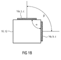
- Fig. 1a shows a soundbar 10 comprising the housing 12 and at least two transducers of a first group 14a to 14c and at least one transducer of a second group 16a to 16c.
- the transducers 14a to 14c are arranged at a front side 12f of the housing 12, wherein the transducers 16a to 16c are arranged on another side, e.g. the top side of the housing 12. From another point of view, that means that the transducers 14a to 14c as well as the transducers 16a to 16c form a tilt having an angle ⁇ of 90° or less, cf.
- Fig. 1 b illustrating a side view of the soundbar 12.
- the transducers 14a to 14c and 16a to 16c of the different groups are preferably, but not necessarily, of the same type.
- the transducers 14a to 14c emit sound substantially in a direction in parallel to the floor, i.e. directly to the listener at listening position 18 so as to enable two-dimensional surround sound.
- the surround sound is based on the common principle of producing virtual surround sound using a soundbar. Virtual surround sound means that a single soundbar generates sound seeming to come from directions where no loudspeakers are posited.
- the sound emitted by the transducers 16a to 16c is radiated in a direction basically against the wall behind the soundbar 10, such that the sound is reflected at the vertical wall.
- the sound reflected at the wall travels now in the direction towards the ceiling, at which the sound is reflected again.
- the second direction is slanted such that the sound reaches the listener at the listening position 18 after being reflected twice. Due to the fact that the sound travels from the ceiling to the listener at the position 18, the radiated sound wave mainly reaches the listener from above. Therefore, it is possible to use these second order reflections for height reproduction. From another point of view that means that the two-dimensional sound reproduction provided by the transducers 14a to 14c is extended vertically to form a three-dimensional sound reproduction at the listener's position 18.
- the transducers 14a and 14c are typically controlled using, for example, two different audio signals (in order to enable two dimensional sound reproduction), wherein the transducers 16a to 16c are typically controlled by another audio signal.
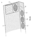
- Fig. 2a shows a top view of a soundbar 10' with three transducers 14a to 14c facing horizontally (e.g. towards the listening area) and one exemplary transducer 16a on the right side of the housing 12', wherein the transducer 16a faces backward and upward back slanted away from the listening area.
- the transducer 16a is arranged within a recess 12r' of the housing 12', wherein the recess 12r' may have a V-shape.
- the transducer 16a is arranged at a plane of the recess 12r' which forms together with the front 12f' of the housing 12' (onto which the transducers 14a to 14c are arranged) an acute angle ⁇ . This angle is illustrated by Fig. 2b .
- the soundbar-like device 10' can be defined as follows: a device 10' that comprises at least three loudspeaker drivers 14a to 14c and 16a that are primarily excited in the same frequency range.
- This device 10' is typically located near the bottom of a television screen, such that a dimension and width are comparable to those of a typical TV screen.
- a height is typically well below 30 cm, while a depth can vary such that it can, e.g. be conventionally placed in front of a TV screen or the TV screen can be based on the device itself.
- the loudspeaker drivers 14a to 14c and 16a may or may not share an enclosure 12', but they will in any case be mechanically connected to each other such that their relative position to each other is fixed or can be fixed, i.e. that the housing does not necessarily form a volume for the transducers 14a to 14c and 16a.
- such device 10' is typically used in conjunction with a TV screen, a standalone usage for music or radio reproduction is also possible.
- At least one loudspeaker driver 16a is arranged or electrically steered such that it emits a sound wave that is consecutively reflected by a vertically oriented surface (like a wall) and then by a horizontally oriented surface before it impinges in the listening area (not shown).
- a vertically oriented surface like a wall
- a horizontally oriented surface before it impinges in the listening area (not shown).
- Arranging a loudspeaker basically means to tilt it accordingly, while an electrical steering can be facilitated using multiple drivers combined with array processing techniques.
- Loudspeaker drivers 16a used for height reproduction will typically be mounted on top of the housing 12' and principally emit the sound in an upward direction.
- the precedence effect which often influences the state of the art approaches, has the following background. Since neither tilting a conventional loudspeaker nor an electrical steering can achieve a perfect directional reproduction, the sound emission in the desired direction is always accompanied by undesired sound emission. If such an undesired sound emission arrives earlier at the listener and with a certain sound pressure level, the reproduction signal will no longer be perceived as coming from above. Since the undesired sound emission is stronger in directions close to the desired direction, it is a clear advantage to aim at a primary radiation direction away from the listener.
- the state-of-the-art proposes a radiation upwards but tilted towards the listener's position (cf. WO 2014/036085 ).
- This orientation is unavoidable when exploiting only first-order reflections. Due to the usage of second order reflections, the means for reducing the precedence effect, e.g. a filter for the high channels, are no longer necessary.
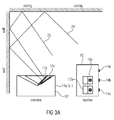
- Fig. 2c shows the soundbar 10' arranged within a room 22 having the walls 22w and the ceiling 22c.
- the soundbar 10' is arranged next to the wall 22w such that the signal output by the transducer 16a is directed against the wall 22w (cf. path 24, part 1).
- the path is between the wall 22w and ceiling 22c (cf. 24, part 2).
- the signal is reflected such that it travels from the ceiling 22c to the listener at the listening position 18 (cf. 24, part 3).
- the traveling path 24 from driver 16a to the listener position 18 is slightly longer than the traveling path of the first order reflection at the ceiling 22c causing only a small attenuation of the desired sound coming from above. But since tilting away the driver from the listener has an even stronger attenuation effect on the undesired direction, e.g. the first direction into which the transducers 14a to 14c of the first group emit the sound, this results in an overall improvement of the desired signal to inference signal ratio. Furthermore, the longer traveling path has the additional benefit of broadening the area which is covered by the sound reflected from the ceiling 22c. A directive reproduction with a given opening angle limits the effective listening area. Hence, a longer traveling distance to the emitted wave front will effectively increase the area where an optimum reproduction is achieved.
- Fig. 2d or 2e show the soundbar 10' within the room 22, wherein the sound path 24 or especially part 1 of the sound path 24, i.e. 24, part 1, is emitted to the TV screen 26 which reflects the sound to the ceiling 22c.
- the difference between the embodiments 22d and 22e is that the screen 26 is mounted on the wall in case of the embodiment of 22d, wherein the television (screen) is positioned on the pedestal soundbar 10' within the embodiment of 22e.
- the soundbar 10' may comprise means for mounting the screen 26. This has two advantages, namely that the soundbar 10' and the television 26 may be arranged somewhere in the room 22 without the need of having the wall 22w behind the soundbar 10'.
- FIG. 2f This setup is illustrated by Fig. 2f showing soundbar 10' in combination with the screen 26, wherein both are positioned in the middle of the room 22.
- the signal emitted by the transducer 16a reaches the ceiling 22w after being reflected by the screen 26 (cf. 24 part 2 of the path 24).
- the vertical reflecting element, namely the television screen 26 is fixed and the position thereof is known. This makes the setup a variable solution for nearly each room.
- FIG. 2g shows the soundbar 10' arranged as discussed with respect to Fig. 2c (i.e. that the soundbar emits a sound signal traveling along the sound path 24 using the transducer 16a), wherein the television 26 is arranged at the front side of the soundbar 10'.
- the transducer 16a is arranged between the wall 22w and the screen 26. This has the effect that the sound emitted by the transducer 16a is shielded by the back side of the screen 26. Expressed in other words, that means that the driver 16a is located behind the TV screen 26.
- the vertically oriented reflecting surface will be the back wall 22w behind the TV screen 26.
- the TV screen 26 acts as an acoustic barrier to further reduce the undesired emission of the sound towards the listener without being reflected. This is considered to further improve the reproduction quality.
- such an arrangement is desirable from an psychologic/esthetic point of view because the upwards pointing loudspeaker driver 16a' is hidden from the listener's eyes and the front of the TV screen 26 can be arranged in line with the front of the device 10'.
- embodiments refer to a system comprising the soundbar, e.g. the soundbar 10 or 10', and a vertically oriented reflector. In this case, or in most cases, the horizontally oriented reflecting object will be the listening room ceiling 22c. However, if the listening room is very high, there might be an additional reflector (not shown) suspended at an appropriate height.
- Fig. 3a shows an enhanced embodiment of the soundbar, namely the soundbar 10".
- the soundbar 10" comprises the transducers 14a to 14c at the front side and the at least one transducer of a second group 16a at the top side. Additionally, a further transducer 17a is arranged at the top side, wherein this further transducer 17a forms a different angle with respect to the transducers 14a to 14c. Consequently, the transducers 17a and 16a form an angle in between, as illustrated by the top view of the device 10".
- the transducers 16a and 17a may be arranged adjacent to each other on the top side, or in more detail within a recess of the top side.
- the transducers 16a and 17a Due to the different tilts of the transducers 16a and 17a, the transducers emit sound signals traveling along the paths 24 and 25, wherein both paths are paths having reflections of a second order. Due to the two different paths 24 and 25, it is possible to transmit two (equal or different) height signals impinging the listener at the listener's position. As illustrated, the two different paths 24 and 25 impinge the listener's position such that one signal (cf. path 25) impinges at the front of the listener's position, wherein the second signal 24 impinges behind the listener at the listening position. Expressed in other words, this means that the two impinging sound signals 24 and 25 have different inclination angles in order to provide a wider listening area.
- Another use case for two or more drivers with different tilts are drivers which are used for the reproduction of different frequency ranges of the signal that is to be reproduced from above. And since different types of speakers, e.g. a broadband speaker and an additional tweeter, have different directivity characteristics, different tilt angles can be used to optimize the radiation pattern.
- transducers 16a and 17a' arranged at the top side of the soundbar 10'" as illustrated by Fig. 3b .
- the transducers 16a and 17a' are arranged in parallel to each other (i.e. have the same angle between the respective transducers 17a' and 16a and the transducers 14a to 14c, wherein the transducers 17a' and 16a are arranged with different distances to the longitudinal side of the transducer 10"" as illustrated by the top view of the transducer 10"". Due to this, the sound signals 24 and 25 impinge at the listener's position such that a wider listening area is covered by their reflected sound 24 and 25.
- the soundbar may also have a different shape, as illustrated by Fig. 4a .
- Fig. 4a shows a soundbar 10""' having a pentagonal housing 12", wherein the transducers 14a to 14c are arranged at the front side 12f" and wherein a plurality of transducers of the second group 16a to 16c are arranged at a beveled plane 12b" which is arranged opposite to the plane 12f".
- the planes 12b" and 12f" and consequently, the directions into which the sound is emitted by the transducers 14a to 14c and 16a to 16c forms an angle ⁇ in between which has more than 90°, e.g. 100° or 110°.
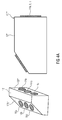
- Fig. 4b shows another embodiment of a housing of a soundbar 10""", wherein the housing 12'" has a rectangular cross-section.
- the transducers 14a to 14c are arranged at the front side 12f"', wherein the transducers 16a arranged at the top side of the housing 12'" is arranged at a portion of the top side which is angled with respect to the entire top side, such that the angle portion of the top side forms an angle ⁇ with respect to the front side 12f"' being larger than 90°.
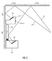
- Fig. 5 shows an exemplary sketch of using more than one soundbar.
- the soundbar 10' is arranged below the TV screen 26, as explained with respect to the embodiment of Fig. 2e , wherein an additional soundbar 10"""' is arranged above the TV screen 26.
- the soundbar 10"""' has an orthogonal shape, wherein the transducers 14a to 14c and 16a of the two different groups are arranged such that same form an angle ⁇ of 90° or less in between.
- the respective second emission direction of the transducer 16a of the two soundbars 10' and 10"""' are selected such that both impinge at the listener's position, cf. part 24 and 24"""'.
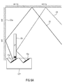
- Fig. 6a shows a setup of the soundbar 10"" which has the two transducers 16a and 17a' being arranged with different distances to the longitudinal edge of the sample 10"", wherein the screen 26 is arranged such that the signal of the transducer 16a is reflected by the screen 26 and such that the signal of the transducer 17a' is emitted behind the screen 26 and reflected by the wall 22w and shielded by the screen 26.
- the two paths 24 and 25 the height audio signal impinges at the listener's position in a manner having a wider listening area.
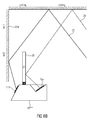
- FIG. 6b A substantially similar situation is illustrated by Fig. 6b , wherein the soundbar 10"""" has the transducer 16a arranged at a recess in the top side and a transducer 17a' arranged at a back side of the housing, wherein the back side and the front side have a tilt ⁇ of less than 90°. Consequently, the signal of the transducer 16a is reflected by the screen 26, wherein the signal of the transducer 17a' is reflected by the wall 22w. As a consequence, the two audio signals 24 and 25 impinge at the listener's position in a manner forming a wider listening area.
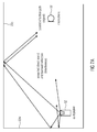
- FIG. 7a shows the test setup in which the test loudspeaker 30 is arranged next to the back wall 22w and the microphone 32 at the listener's position.
- the test loudspeaker 30 is generally oriented upwards, wherein the tilt is varied during the measurement.
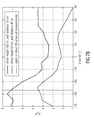
- Fig. 7b shows a diagram of the desired reflection path signal (p signal ) and the unwanted interference signal (p interference ) plotted over the driver tilt.
- the upward oriented loudspeaker 30, is placed closely to the wall 22w at different heights and wall distances, and the microphone 32 is at 2.5 meter from the wall.
- the transfer function between the loudspeaker 30 and the microphone 32 is measured for variety of driver tilt angle ranging from -45° to +45°, wherein negative angles describe an orientation towards the back wall 22w.
- Sound reaching the listener from the front, either directly or via a first order reflection, are considered unwanted and their respective energy is accumulated into the total interference power (p interference ). All sound reaching the listener via reflections from the top, i.e. from the ceiling 22c, e.g. via first order or second order reflections (i.e.
- the optimum loudspeaker tilt angle is indicated by a maximum of the energetic ratio between the signal and interference, p s to p i .
- An advantage of the backward-oriented loudspeaker is that less energy propagates on the direct unwanted path to the listener as compared to the case when the loudspeaker is oriented directly towards the ceiling (cf. Fig. 7b ). This effect is even emphasized towards higher frequencies, as the loudspeaker starts to focus.
- transducer 16a just one transducer of the second group (cf. reference numeral 16a) is arranged at the top side or back side or the recess of the soundbar, it should be noted that preferably a plurality of transducers of the second group are arranged at the top side.
- the side at which the transducers of the second group are arranged has been discussed so to form an angle ⁇ being smaller than 90° to enable angle of larger than 90° between the first and second emission direction, it should be noted that the angle ⁇ may also be 90° or more (cf. Fig. 1 b) . However the interior angle ⁇ may also be equal or larger than the 90° when beamforming is used to direct the second direction so that the angle ⁇ between the first and the second direction amounts to at least 90° or, preferably, to more than 90°.
- each audio signal may comprise many channels
- the first / second audio signal may comprise many channels
- the height information of the second audio signal may be carried by a separated channel or generated by an upmixing.
Landscapes
- Physics & Mathematics (AREA)
- Engineering & Computer Science (AREA)
- Acoustics & Sound (AREA)
- Signal Processing (AREA)
- Health & Medical Sciences (AREA)
- Otolaryngology (AREA)
- General Health & Medical Sciences (AREA)
- Obtaining Desirable Characteristics In Audible-Bandwidth Transducers (AREA)
- Stereophonic System (AREA)
- Circuit For Audible Band Transducer (AREA)
Priority Applications (13)
| Application Number | Priority Date | Filing Date | Title |
|---|---|---|---|
| EP15179585.3A EP3128762A1 (de) | 2015-08-03 | 2015-08-03 | Soundbar |
| CN201680057762.2A CN108141662B (zh) | 2015-08-03 | 2016-07-21 | 条形音箱 |
| TR2019/10361T TR201910361T4 (tr) | 2015-08-03 | 2016-07-21 | Ses çubuğu. |
| RU2018107647A RU2713169C2 (ru) | 2015-08-03 | 2016-07-21 | Звуковая панель |
| ES16742274T ES2739174T3 (es) | 2015-08-03 | 2016-07-21 | Barra de sonido |
| JP2018505652A JP6771540B2 (ja) | 2015-08-03 | 2016-07-21 | サウンドバー |
| BR112018002264-0A BR112018002264B1 (pt) | 2015-08-03 | 2016-07-21 | Soundbar |
| MX2018001356A MX375305B (es) | 2015-08-03 | 2016-07-21 | Barra de sonido |
| CA2994382A CA2994382C (en) | 2015-08-03 | 2016-07-21 | Soundbar |
| KR1020187003205A KR102249482B1 (ko) | 2015-08-03 | 2016-07-21 | 사운드바 |
| EP16742274.0A EP3332556B1 (de) | 2015-08-03 | 2016-07-21 | Soundbar |
| PCT/EP2016/067393 WO2017021162A1 (en) | 2015-08-03 | 2016-07-21 | Soundbar |
| US15/887,182 US10863276B2 (en) | 2015-08-03 | 2018-02-02 | Soundbar |
Applications Claiming Priority (1)
| Application Number | Priority Date | Filing Date | Title |
|---|---|---|---|
| EP15179585.3A EP3128762A1 (de) | 2015-08-03 | 2015-08-03 | Soundbar |
Publications (1)
| Publication Number | Publication Date |
|---|---|
| EP3128762A1 true EP3128762A1 (de) | 2017-02-08 |
Family
ID=53773357
Family Applications (2)
| Application Number | Title | Priority Date | Filing Date |
|---|---|---|---|
| EP15179585.3A Withdrawn EP3128762A1 (de) | 2015-08-03 | 2015-08-03 | Soundbar |
| EP16742274.0A Active EP3332556B1 (de) | 2015-08-03 | 2016-07-21 | Soundbar |
Family Applications After (1)
| Application Number | Title | Priority Date | Filing Date |
|---|---|---|---|
| EP16742274.0A Active EP3332556B1 (de) | 2015-08-03 | 2016-07-21 | Soundbar |
Country Status (11)
| Country | Link |
|---|---|
| US (1) | US10863276B2 (de) |
| EP (2) | EP3128762A1 (de) |
| JP (1) | JP6771540B2 (de) |
| KR (1) | KR102249482B1 (de) |
| CN (1) | CN108141662B (de) |
| CA (1) | CA2994382C (de) |
| ES (1) | ES2739174T3 (de) |
| MX (1) | MX375305B (de) |
| RU (1) | RU2713169C2 (de) |
| TR (1) | TR201910361T4 (de) |
| WO (1) | WO2017021162A1 (de) |
Cited By (4)
| Publication number | Priority date | Publication date | Assignee | Title |
|---|---|---|---|---|
| CN106101939A (zh) * | 2016-06-17 | 2016-11-09 | 无锡杰夫电声股份有限公司 | 虚拟七声道条形音箱 |
| WO2023284963A1 (en) * | 2021-07-15 | 2023-01-19 | Huawei Technologies Co., Ltd. | Audio device and method for producing a sound field using beamforming |
| US11895461B2 (en) | 2019-12-20 | 2024-02-06 | Sony Group Corporation | Acoustic reproduction system, display device, and calibration method |
| EP4304164A4 (de) * | 2021-04-13 | 2024-07-31 | Huawei Technologies Co., Ltd. | Anzeigevorrichtung und audioausgabeverfahren dafür |
Families Citing this family (14)
| Publication number | Priority date | Publication date | Assignee | Title |
|---|---|---|---|---|
| WO2017209196A1 (ja) * | 2016-05-31 | 2017-12-07 | シャープ株式会社 | スピーカシステム、音声信号レンダリング装置およびプログラム |
| US11363380B2 (en) * | 2018-07-31 | 2022-06-14 | Hewlett-Packard Development Company, L.P. | Stereophonic devices |
| KR102536323B1 (ko) * | 2018-08-16 | 2023-05-25 | 삼성전자주식회사 | 스피커 장치 및 그 제어 방법 |
| US12120494B2 (en) | 2018-11-15 | 2024-10-15 | Polk Audio, Llc | Loudspeaker system with overhead sound image generating (e.g., ATMOS™) elevation module and method and apparatus for direct signal cancellation |
| WO2020127836A1 (en) | 2018-12-21 | 2020-06-25 | Fraunhofer-Gesellschaft zur Förderung der angewandten Forschung e.V. | Sound reproduction/simulation system and method for simulating a sound reproduction |
| KR102651381B1 (ko) * | 2019-01-11 | 2024-03-26 | 소니그룹주식회사 | 사운드바, 오디오 신호 처리 방법 및 프로그램 |
| US11882399B2 (en) | 2019-02-27 | 2024-01-23 | Dolby Laboratories Licensing Corporation | Acoustic reflector for height channel speaker |
| US11937066B2 (en) | 2019-03-07 | 2024-03-19 | Polk Audio, Llc | Active cancellation of a height-channel soundbar array's forward sound radiation |
| EP3726858A1 (de) | 2019-04-16 | 2020-10-21 | Fraunhofer Gesellschaft zur Förderung der Angewand | Reproduktion einer unteren schicht |
| US10856082B1 (en) * | 2019-10-09 | 2020-12-01 | Echowell Electronic Co., Ltd. | Audio system with sound-field-type nature sound effect |
| KR102711321B1 (ko) | 2020-01-02 | 2024-09-30 | 삼성전자주식회사 | 디스플레이 장치 및 그 제어 방법 |
| WO2022183231A1 (de) | 2021-03-02 | 2022-09-09 | Atmoky Gmbh | Verfahren zur erzeugung von audiosignalfiltern für audiosignale zur erzeugung virtueller schallquellen |
| KR102654949B1 (ko) * | 2022-08-01 | 2024-05-09 | 주식회사 제이디솔루션 | 초지향성 스피커가 탑재된 사운드바 |
| FR3167514A1 (fr) * | 2024-10-16 | 2026-04-17 | Focal Jmlab | Enceinte de diffusion de son par reflexion, procede de generation de son spatialise et installation de cinema a domicile associes |
Citations (17)
| Publication number | Priority date | Publication date | Assignee | Title |
|---|---|---|---|---|
| US2179840A (en) | 1938-05-03 | 1939-11-14 | Frida Bucky | Loudspeaker arrangement |
| US2710662A (en) | 1948-12-23 | 1955-06-14 | Armour Res Found | Sound projection system |
| US2831060A (en) | 1954-10-18 | 1958-04-15 | Philips Corp | Method of reproducing speech and music by means of loudspeakers |
| US2896736A (en) | 1955-08-15 | 1959-07-28 | John E Karlson | Acoustic system |
| US3241631A (en) | 1964-01-31 | 1966-03-22 | Manieri Domenico | High-fidelity column-type stereomonophonic diffuser with regulated sound deflection |
| US3582553A (en) | 1967-12-04 | 1971-06-01 | Bose Corp | Loudspeaker system |
| US3627948A (en) | 1969-08-18 | 1971-12-14 | Electro Voice | Stereo loudspeaker system |
| US3933219A (en) | 1974-04-08 | 1976-01-20 | Ambient, Inc. | Speaker system |
| US4112256A (en) | 1973-08-24 | 1978-09-05 | Stig Carlsson | Loudspeaker and stereophonic loudspeaker system |
| GB2098025A (en) * | 1981-03-04 | 1982-11-10 | Onkyo Kk | Loudspeaker system |
| US4837825A (en) | 1987-02-28 | 1989-06-06 | Shivers Clarence L | Passive ambience recovery system for the reproduction of sound |
| US5953432A (en) | 1993-01-07 | 1999-09-14 | Pioneer Electronic Corporation | Line source speaker system |
| EP2400782A1 (de) * | 2010-06-25 | 2011-12-28 | NOM Juridique | Monoblock-Stereo-Vorrichtung einer verstärkten Lautsprecherbox |
| US8345883B2 (en) | 2003-08-08 | 2013-01-01 | Yamaha Corporation | Audio playback method and apparatus using line array speaker unit |
| WO2014036085A1 (en) | 2012-08-31 | 2014-03-06 | Dolby Laboratories Licensing Corporation | Reflected sound rendering for object-based audio |
| FR2999855A1 (fr) * | 2012-12-17 | 2014-06-20 | Cc Lab | Dispositif constitue de deux enceintes stereophoniques |
| WO2014107714A1 (en) | 2013-01-07 | 2014-07-10 | Dolby Laboratories Licensing Corporation | Virtual height filter for reflected sound rendering using upward firing drivers |
Family Cites Families (24)
| Publication number | Priority date | Publication date | Assignee | Title |
|---|---|---|---|---|
| JPS53158233U (de) * | 1977-05-18 | 1978-12-12 | ||
| DE3142462A1 (de) * | 1980-10-28 | 1982-05-27 | Hans-Peter 7000 Stuttgart Pfeiffer | Lautsprecheranordnung |
| DE3201455C2 (de) * | 1982-01-19 | 1985-09-19 | Dieter 7447 Aichtal Wagner | Lautsprecherbox |
| JPS59201600A (ja) * | 1983-04-28 | 1984-11-15 | Mitsubishi Electric Corp | 音声多重内蔵カラ−テレビジヨン受像機 |
| JPS61191694U (de) * | 1985-05-20 | 1986-11-28 | ||
| JP3194386B2 (ja) | 1991-02-16 | 2001-07-30 | 株式会社ニッポン放送 | 立体音再生装置 |
| US5809150A (en) | 1995-06-28 | 1998-09-15 | Eberbach; Steven J. | Surround sound loudspeaker system |
| US6175489B1 (en) * | 1998-06-04 | 2001-01-16 | Compaq Computer Corporation | Onboard speaker system for portable computers which maximizes broad spatial impression |
| US7142683B1 (en) * | 1999-03-01 | 2006-11-28 | Hewlett-Packard Development Company, L.P. | Computer with acoustic driver built into acoustically leaky chassis |
| CA2542517A1 (en) * | 2002-11-22 | 2004-06-10 | David John Tasker | Speaker system |
| JP4007254B2 (ja) * | 2003-06-02 | 2007-11-14 | ヤマハ株式会社 | アレースピーカーシステム |
| JP4251077B2 (ja) | 2004-01-07 | 2009-04-08 | ヤマハ株式会社 | スピーカ装置 |
| US7606380B2 (en) * | 2006-04-28 | 2009-10-20 | Cirrus Logic, Inc. | Method and system for sound beam-forming using internal device speakers in conjunction with external speakers |
| WO2007127781A2 (en) | 2006-04-28 | 2007-11-08 | Cirrus Logic, Inc. | Method and system for surround sound beam-forming using vertically displaced drivers |
| US7606377B2 (en) * | 2006-05-12 | 2009-10-20 | Cirrus Logic, Inc. | Method and system for surround sound beam-forming using vertically displaced drivers |
| WO2007127821A2 (en) | 2006-04-28 | 2007-11-08 | Cirrus Logic, Inc. | Method and apparatus for calibrating a sound beam-forming system |
| CN201425837Y (zh) * | 2008-11-12 | 2010-03-17 | 北京歌尔泰克科技有限公司 | 便携式声频重放设备 |
| CN101964937A (zh) | 2009-07-23 | 2011-02-02 | 先歌国际影音股份有限公司 | 多方向发声系统 |
| CN201550266U (zh) * | 2009-09-29 | 2010-08-11 | 先歌国际影音股份有限公司 | 多方向发声系统 |
| JP5640911B2 (ja) * | 2011-06-30 | 2014-12-17 | ヤマハ株式会社 | スピーカアレイ装置 |
| CN102572651A (zh) * | 2012-01-13 | 2012-07-11 | 中山声雅科技有限公司 | 环绕声多媒体音响及制作环绕立体声的方法 |
| CN102595282B (zh) * | 2012-02-20 | 2014-07-02 | 东莞市三基音响科技有限公司 | 一种多媒体视听装置集成方法及系统 |
| US9826328B2 (en) | 2012-08-31 | 2017-11-21 | Dolby Laboratories Licensing Corporation | System for rendering and playback of object based audio in various listening environments |
| US10440492B2 (en) * | 2014-01-10 | 2019-10-08 | Dolby Laboratories Licensing Corporation | Calibration of virtual height speakers using programmable portable devices |
-
2015
- 2015-08-03 EP EP15179585.3A patent/EP3128762A1/de not_active Withdrawn
-
2016
- 2016-07-21 CN CN201680057762.2A patent/CN108141662B/zh active Active
- 2016-07-21 RU RU2018107647A patent/RU2713169C2/ru active
- 2016-07-21 JP JP2018505652A patent/JP6771540B2/ja active Active
- 2016-07-21 EP EP16742274.0A patent/EP3332556B1/de active Active
- 2016-07-21 WO PCT/EP2016/067393 patent/WO2017021162A1/en not_active Ceased
- 2016-07-21 ES ES16742274T patent/ES2739174T3/es active Active
- 2016-07-21 CA CA2994382A patent/CA2994382C/en active Active
- 2016-07-21 MX MX2018001356A patent/MX375305B/es active IP Right Grant
- 2016-07-21 KR KR1020187003205A patent/KR102249482B1/ko active Active
- 2016-07-21 TR TR2019/10361T patent/TR201910361T4/tr unknown
-
2018
- 2018-02-02 US US15/887,182 patent/US10863276B2/en active Active
Patent Citations (17)
| Publication number | Priority date | Publication date | Assignee | Title |
|---|---|---|---|---|
| US2179840A (en) | 1938-05-03 | 1939-11-14 | Frida Bucky | Loudspeaker arrangement |
| US2710662A (en) | 1948-12-23 | 1955-06-14 | Armour Res Found | Sound projection system |
| US2831060A (en) | 1954-10-18 | 1958-04-15 | Philips Corp | Method of reproducing speech and music by means of loudspeakers |
| US2896736A (en) | 1955-08-15 | 1959-07-28 | John E Karlson | Acoustic system |
| US3241631A (en) | 1964-01-31 | 1966-03-22 | Manieri Domenico | High-fidelity column-type stereomonophonic diffuser with regulated sound deflection |
| US3582553A (en) | 1967-12-04 | 1971-06-01 | Bose Corp | Loudspeaker system |
| US3627948A (en) | 1969-08-18 | 1971-12-14 | Electro Voice | Stereo loudspeaker system |
| US4112256A (en) | 1973-08-24 | 1978-09-05 | Stig Carlsson | Loudspeaker and stereophonic loudspeaker system |
| US3933219A (en) | 1974-04-08 | 1976-01-20 | Ambient, Inc. | Speaker system |
| GB2098025A (en) * | 1981-03-04 | 1982-11-10 | Onkyo Kk | Loudspeaker system |
| US4837825A (en) | 1987-02-28 | 1989-06-06 | Shivers Clarence L | Passive ambience recovery system for the reproduction of sound |
| US5953432A (en) | 1993-01-07 | 1999-09-14 | Pioneer Electronic Corporation | Line source speaker system |
| US8345883B2 (en) | 2003-08-08 | 2013-01-01 | Yamaha Corporation | Audio playback method and apparatus using line array speaker unit |
| EP2400782A1 (de) * | 2010-06-25 | 2011-12-28 | NOM Juridique | Monoblock-Stereo-Vorrichtung einer verstärkten Lautsprecherbox |
| WO2014036085A1 (en) | 2012-08-31 | 2014-03-06 | Dolby Laboratories Licensing Corporation | Reflected sound rendering for object-based audio |
| FR2999855A1 (fr) * | 2012-12-17 | 2014-06-20 | Cc Lab | Dispositif constitue de deux enceintes stereophoniques |
| WO2014107714A1 (en) | 2013-01-07 | 2014-07-10 | Dolby Laboratories Licensing Corporation | Virtual height filter for reflected sound rendering using upward firing drivers |
Cited By (4)
| Publication number | Priority date | Publication date | Assignee | Title |
|---|---|---|---|---|
| CN106101939A (zh) * | 2016-06-17 | 2016-11-09 | 无锡杰夫电声股份有限公司 | 虚拟七声道条形音箱 |
| US11895461B2 (en) | 2019-12-20 | 2024-02-06 | Sony Group Corporation | Acoustic reproduction system, display device, and calibration method |
| EP4304164A4 (de) * | 2021-04-13 | 2024-07-31 | Huawei Technologies Co., Ltd. | Anzeigevorrichtung und audioausgabeverfahren dafür |
| WO2023284963A1 (en) * | 2021-07-15 | 2023-01-19 | Huawei Technologies Co., Ltd. | Audio device and method for producing a sound field using beamforming |
Also Published As
| Publication number | Publication date |
|---|---|
| CN108141662B (zh) | 2021-03-02 |
| CA2994382A1 (en) | 2017-02-09 |
| RU2018107647A (ru) | 2019-09-05 |
| KR102249482B1 (ko) | 2021-05-06 |
| EP3332556B1 (de) | 2019-05-22 |
| MX2018001356A (es) | 2018-09-05 |
| CN108141662A (zh) | 2018-06-08 |
| JP6771540B2 (ja) | 2020-10-21 |
| WO2017021162A1 (en) | 2017-02-09 |
| EP3332556A1 (de) | 2018-06-13 |
| US20180184202A1 (en) | 2018-06-28 |
| BR112018002264A2 (pt) | 2018-09-18 |
| TR201910361T4 (tr) | 2019-08-21 |
| CA2994382C (en) | 2023-04-25 |
| ES2739174T3 (es) | 2020-01-29 |
| MX375305B (es) | 2025-03-06 |
| US10863276B2 (en) | 2020-12-08 |
| JP2018527808A (ja) | 2018-09-20 |
| KR20180059423A (ko) | 2018-06-04 |
| RU2018107647A3 (de) | 2019-09-05 |
| RU2713169C2 (ru) | 2020-02-04 |
Similar Documents
| Publication | Publication Date | Title |
|---|---|---|
| US10863276B2 (en) | Soundbar | |
| EP1600035B1 (de) | Schallstrahl-lautsprechersystem | |
| CN1647579B (zh) | 带有成形声场的扬声器 | |
| EP3556112B1 (de) | Lautsprecher mit aufwärtsgerichtetem breitbandtreiber für reflektierte tonprojektion | |
| CN101971643B (zh) | 扬声器阵列和用于扬声器阵列的驱动器布置 | |
| JPH06197293A (ja) | テレビジョンセットのスピーカシステム | |
| US20170251296A1 (en) | Loudspeaker with narrow dispersion | |
| US8873787B2 (en) | Two-way audio speaker arrangement | |
| US9838789B2 (en) | Honeycomb speaker system | |
| CN113574910B (zh) | 高置声道扬声器及相关方法和系统 | |
| CN1965608B (zh) | 具有几何和电子辐射控制的公共广播系统 | |
| JP7636529B2 (ja) | サウンドバー | |
| BR112018002264B1 (pt) | Soundbar | |
| GB2256773A (en) | Loudspeaker uinit |
Legal Events
| Date | Code | Title | Description |
|---|---|---|---|
| PUAI | Public reference made under article 153(3) epc to a published international application that has entered the european phase |
Free format text: ORIGINAL CODE: 0009012 |
|
| STAA | Information on the status of an ep patent application or granted ep patent |
Free format text: STATUS: THE APPLICATION HAS BEEN PUBLISHED |
|
| AK | Designated contracting states |
Kind code of ref document: A1 Designated state(s): AL AT BE BG CH CY CZ DE DK EE ES FI FR GB GR HR HU IE IS IT LI LT LU LV MC MK MT NL NO PL PT RO RS SE SI SK SM TR |
|
| AX | Request for extension of the european patent |
Extension state: BA ME |
|
| STAA | Information on the status of an ep patent application or granted ep patent |
Free format text: STATUS: THE APPLICATION IS DEEMED TO BE WITHDRAWN |
|
| 18D | Application deemed to be withdrawn |
Effective date: 20170809 |