EP3128876B1 - Vorhangdrahtbefestigungssystem eines fensterrahmens - Google Patents
Vorhangdrahtbefestigungssystem eines fensterrahmens Download PDFInfo
- Publication number
- EP3128876B1 EP3128876B1 EP15741786.6A EP15741786A EP3128876B1 EP 3128876 B1 EP3128876 B1 EP 3128876B1 EP 15741786 A EP15741786 A EP 15741786A EP 3128876 B1 EP3128876 B1 EP 3128876B1
- Authority
- EP
- European Patent Office
- Prior art keywords
- mounting bracket
- curtain wire
- cover element
- wire
- curtain
- Prior art date
- Legal status (The legal status is an assumption and is not a legal conclusion. Google has not performed a legal analysis and makes no representation as to the accuracy of the status listed.)
- Active
Links
Images



Classifications
-
- A—HUMAN NECESSITIES
- A47—FURNITURE; DOMESTIC ARTICLES OR APPLIANCES; COFFEE MILLS; SPICE MILLS; SUCTION CLEANERS IN GENERAL
- A47H—FURNISHINGS FOR WINDOWS OR DOORS
- A47H1/00—Curtain suspension devices
- A47H1/18—Other curtain suspension devices, e.g. wire, cord, springs
-
- A—HUMAN NECESSITIES
- A47—FURNITURE; DOMESTIC ARTICLES OR APPLIANCES; COFFEE MILLS; SPICE MILLS; SUCTION CLEANERS IN GENERAL
- A47H—FURNISHINGS FOR WINDOWS OR DOORS
- A47H1/00—Curtain suspension devices
- A47H1/18—Other curtain suspension devices, e.g. wire, cord, springs
- A47H1/19—Devices for mounting the wire, cord, or the like
-
- F—MECHANICAL ENGINEERING; LIGHTING; HEATING; WEAPONS; BLASTING
- F16—ENGINEERING ELEMENTS AND UNITS; GENERAL MEASURES FOR PRODUCING AND MAINTAINING EFFECTIVE FUNCTIONING OF MACHINES OR INSTALLATIONS; THERMAL INSULATION IN GENERAL
- F16M—FRAMES, CASINGS OR BEDS OF ENGINES, MACHINES OR APPARATUS, NOT SPECIFIC TO ENGINES, MACHINES OR APPARATUS PROVIDED FOR ELSEWHERE; STANDS; SUPPORTS
- F16M13/00—Other supports for positioning apparatus or articles; Means for steadying hand-held apparatus or articles
- F16M13/02—Other supports for positioning apparatus or articles; Means for steadying hand-held apparatus or articles for supporting on, or attaching to, an object, e.g. tree, gate, window-frame, cycle
Definitions
- Present invention relates to a curtain wire fastening system onto a window frame, when said curtain wire is intended for hanging a curtain in front of a window.
- a curtain suspension system comprising at both sides of a window frame a mounting bracket formed from wire, where to the mounting bracket an end of a curtain wire or rod for suspending a curtain is attached.
- a shortcoming of that design is that in use neither said mounting brackets nor the ends of the curtain wire attached to said mounting brackets are covered for safety, meaning that when accidentally coming into contact with said elements a user can get scratched or his clothes might get stuck by a projecting structure part. As a result the whole suspension system could be pulled off from the window frame.
- a curtain wire fastening system onto a window frame comprising at both ends of the curtain wire a mounting bracket fastened onto the window frame, where one end of the mounting bracket is intended to be fastened behind the corresponding outer lateral edge of the window frame and at the other end of the mounting bracket a fixing element is formed for fastening the end of the curtain wire.
- a shortcoming of that design is that fastening the ends of the curtain wire to the mounting brackets during installation is rather complicated.
- the aim of the present invention is to provide a curtain wire fastening system onto a window frame, which is safe to use, meaning that all potentially dangerous projecting elements are covered when in use and that which can be readily installed without special tools.
- Another aim of the present invention is to provide a possibility to change and/or refresh the appearance of the fastening system.
- the present invention provides a curtain wire fastening system onto a window frame, comprising at both ends of the curtain wire an elongated mounting bracket fixed respectively onto the right and left vertical frame part of the window frame, where one end of the mounting bracket is intended to be fastened behind the corresponding outer lateral edge of the window frame and at the other end of the mounting bracket a fixing element is formed for fastening the end of the curtain wire.
- a cover element comprising the cavity is placed so that inside said cavity there is placed the end of the elongated mounting bracket comprising a fixing element for fastening the end of the curtain wire and the end of said curtain wire attached to said fixing element.
- the cavity of the cover element is surrounded at least by two end walls and by a mainly cylindrical side wall, wherein said cylindrical side wall comprises two slots, one slot being intended for the end of the mounting bracket and the other slot is intended for the end of the curtain wire, and one of the end walls is formed by a cap fixed onto the cover element.
- the cross-section of the side wall of the cover element can be also polygonal, oval, square, etc.
- the cap is fixed onto the cover element with the help of a snap-fit or an interference fit.
- the surface of the cap i.e. the surface, which during use is facing a user
- the outer shape of the cap can have any desired shape -round, convex, square, polygonal, trapezoid, rectangular, flower-shaped, etc.
- the cavity of the cover element is surrounded by one end wall and with a mainly cylindrical side wall, where said cylindrical side wall comprises two slots, one for the end of the mounting bracket and the other for the end of the curtain wire.
- fastening means of said cover element is formed by a groove, where said groove is formed inside the cavity of the cover element into one end wall between two slots in the cylindrical side wall. Said groove is intended to receive the end of the mounting bracket comprising the fixing element.
- the elongated mounting bracket is formed from wire material, one end of which is turned back so that it comprises an end part turned mainly crosswise in respect to the elongated mounting bracket and a tip which is turned at an angle in respect to the end part.
- a mainly U-shaped fastening element is formed, where arms of said U-shaped part are mainly crosswise in respect to the elongated part of the mounting bracket and the arm of the U-shaped part connected to the elongated part of the mounting bracket comprises a notch for catching a hook or loop at the end of the curtain wire.
- the cover element is fastened by a groove in the end wall to the mounting bracket so that at least the end of the arm of the U-shaped part connected to the elongated part of the mounting bracket and a part of the elongated mounting bracket are fixed into the groove.
- the cover element is fastened by a groove in the end wall to the mounting bracket so that at least an arc part connecting the arms of the U-shaped part at the end of the mounting bracket is fixed into the groove.
- Figures 1 to 4 represent only the part of the curtain wire fastening system onto a window frame which is installed onto the left vertical part of the window frame and from which the curtain wire runs towards the right part of the window frame - it is obvious to the person skilled in the art that the right vertical frame part comprises exactly the same structure of the fastening system, from which the curtain wire runs towards the left part of the window frame.
- the curtain wire fastening system to be installed onto the window frame have exactly the same design both on the left and on the right. Therefore in drawings only the part of the curtain wire fastening system is represented which is installed onto the left part of the window frame.
- the curtain wire 1 fastening system onto a window frame 2 comprises at both ends of the curtain wire an elongated mounting bracket 3 to be installed onto the window frame 2, see Figures 1 to 4 and 16 .
- One end 4 of the mounting bracket 3 is intended to be fastened behind the corresponding outer lateral edge of the window frame 2.
- a fixing element 5 is formed for fastening the end 6 of the curtain wire 1.
- a cover element 7 comprising a cavity is fixed so that the end of the mounting bracket 3 comprising the fixing element 5 and the end 6 of the curtain wire 1 attached to said fixing element 5 is placed inside the cavity of the cover element 7.
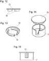
- the cavity of the cover element 7 is surrounded by two end walls 8, 9 and with a mainly cylindrical side wall 10, whereby said cylindrical side wall 10 comprises two slots 11, 12, one slot being intended for the end of the mounting bracket 3 comprising fixing element 5 and the other slot is intended for the end 6 of the curtain wire 1, and one end wall 9 is formed by a cap 13 fixed onto the cover element, Figures 1, 2 , 5 to 15 .
- the cavity of the cover element 7 is surrounded by one end wall 8 and by the mainly cylindrical side wall 10, where said cylindrical side wall 10 comprises two slots 11, 12, one for the end of the mounting bracket 3 comprising a fixing element 5 and the other for the end 6 of the curtain wire 1, Figures 3 to 11 .
- the fastening means of said cover element 7 is formed by a groove 14, when said groove is formed inside the cavity of the cover element 7 into one end wall 8 between two slots 11, 12 in the cylindrical side wall 10 for receiving at least the end of the mounting bracket 3 comprising the fixing element 5, Figure 5 into said groove.
- cap 13 forms the other end wall of the cover element 7
- said cap 13 is fixed onto the cover element 7 with the help of a snap-fit 15 or an interference fit, Figures 12 to 15 .
- the elongated mounting bracket 3 is formed from wire material, one end of which is turned back so that it comprises an end part 4 turned mainly crosswise in respect to the elongated part of the mounting bracket 3 and a tip 16 which is turned at an angle in respect to the end part 4, Figure 16 .
- a mainly U-shaped fastening element 5 is formed, where arms 17, 18 of said U-shaped part are mainly crosswise in respect to the elongated part of the mounting bracket 3 and the arm 17 of the U-shaped part connected to the elongated part of the mounting bracket 3 comprises a notch 19 for fixing a hook or loop at the end 6 of the curtain wire.
- the mounting bracket 3 is made of metal wire.
- the mounting bracket can also be made of metal strip, which is also covered with plastic covering.
- the end wall 8 of the cover element 7 is placed against the window frame 2, then the mounting bracket 3 comprising the end part 4 with the angled tip 16 is placed behind the outer lateral edge of the window frame 2 and the other end of the mounting bracket 3 is pushed into the groove 14 in the end wall 8 of the cover element 7 so that the mounting bracket 3 extends out from the slot 7 of the cover element 7.
- the same is carried out on the other side of the window frame, Figures 1 and 2 .
- a cap 13 is placed onto the cover element 7, where the cap forms the second end wall 9 of the cover element 7.
- the cap 13 is fixed with a snap-fit 15. But also an interference fit may be used.
- the mounting bracket 3 comprising the end part 4 with the angled tip 16 is placed behind the outer lateral edge of the window frame 2. The same is carried out on the other side of the window frame, Figures 3 and 4 .
- the cover element 7 comprising the groove 14 in the end wall 8 is pushed onto the fixing element 5 of the mounting bracket 3 so that the mounting bracket 3 extends from the slot 11 and the curtain wire 1 extends from the slot 12. The same is carried out on the other side of the window frame.
- the curtain wire 1 is made of flexible material, such as spirally wound spring wire, which has a plastic coating and which has openings at both ends. A hook or a loop is screwed into those openings forming the end 6 of the curtain wire 1 and which is used to attach the curtain wire to the fixing element 5 of the mounting bracket 3.
- the curtain wire may also be braided cable or string, which is stretched by its ends between the fixing elements of the mounting brackets on the left and right vertical parts of the window frame.
Landscapes
- Engineering & Computer Science (AREA)
- General Engineering & Computer Science (AREA)
- Mechanical Engineering (AREA)
- Curtains And Furnishings For Windows Or Doors (AREA)
Claims (8)
- Ein Vorhangdrahtbefestigungssystem (1) eines Fensterrahmens (2), welches beide Enden (6) des Gardinendrahtes (1), eine verlängerte Befestigungsklammer (3), welche jeweils auf dem rechten und linken vertikalen Teil des Fensterrahmens (2) befestigt sind, umfasst, wobei das Anbringen eines Endes (4) der Befestigungsklammer (3) hinter der entsprechenden äußeren Kante des Fensterrahmens (2) vorgenommen werden muss und am anderen Ende der Befestigungsklammer (3) ist ein Befestigungselement (5) für das Spannen des Endes (6) des Gardinendrahtes (1), dadurch gekennzeichnet, dass ein Deckelement (7) das ein Loch enthält um das Ende der Befestigungsklammer (3), das das Befestigungselement (5) umfasst, so montiert ist, dass innerhalb des benannten Loches das Ende der benannten verlängerten Befestigungsklammer (3) montiert ist, welches das Befestigungselement (5) für das Spannen des genannten Endes (6) des Gardinendrahtes (1) und das genannte Ende (6) des Gardinendrahtes (1) an genanntes Befestigungselement (5) befestigt.
- Das Vorhangdrahtbefestigungssystem (1) gemäß Anspruch 1, dadurch gekennzeichnet, dass die Aushöhlung des Deckelementes (7) mindestens von zwei Endwänden (8, 9) und von einer hauptsächlich zylindrischen Seitenwand (10) umgeben ist, wobei die benannte zylindrische Seitenwand (10) zwei Aussparungen (11, 12) umfasst, eine davon für das Ende der Befestigungsklammer (3) und die andere für das Ende (6) des Gardinendrahtes (1), und eine der Endwände (9) ist durch eine Kappe (13) geformt, die an das Deckelement (7) befestigt ist.
- Das Vorhangdrahtbefestigungssystem (1) gemäß Anspruch 2, dadurch gekennzeichnet, dass die Kappe (13) an das Deckelement (7) mit der Hilfe eines Schnappverschlusses und einer Presspassung befestigt ist.
- Das Vorhangdrahtbefestigungssystem (1), gemäß Anspruch 1, dadurch gekennzeichnet, dass die Aushöhlung der Deckelementes (7) von einer Seitenwand (8) und von einer hauptsächlich zylindrischen Seitenwand (10) umgeben ist, wobei die genannte zylindrische Seitenwand (10) zwei Aussparungen (11, 12) umfasst, eine für das Ende der Befestigungsklammer (3) und die andere für das Ende (6) des Gardinendrahtes (1).
- Das Vorhangdrahtbefestigungssystem gemäß einem der vorangehenden Ansprüche, dadurch gekennzeichnet, dass die Spannungsweise des genannte Deckelementes (7) von einer Rille (14) geformt ist, wobei die genannte Rille (14) innerhalb einer Aussparung des Deckelementes (7) in eine Endwand (8) zwischen den zwei Aussparungen (11, 12) in der zylindrischen Seitendwand (10) geformt ist, um das Ende der Befestigungsklammer (3) das das Befestigungselement (5) umfasst, zu erhalten.
- Das Vorhangdrahtbefestigungssystem (1) gemäß Anspruch 1, dadurch gekennzeichnet, dass die verlängerte Befestigungsklammer (3) durch ein Drahtmaterial geformt ist, bei dem ein Ende des Drahtes so zurückgeschwungen ist, dass es das Endteil (4), das hauptsächlich im rechten Winkel zur verlängerten Befestigungsklammer (3) gebeugt ist, und eine Spitze (16), die einen Winkel zum Endteil (4) formt, umfasst, und am anderen Ende der Befestigungsklammer (3) ein hauptsächlich U-förmiges Befestigungselement (5) formt, wo die Arme (17, 18) des genannten U-förmigen Teils hauptsächlich im rechten Winkel zum verlängerten Teil der Befestigungsklammer (3) gebeugt sind und der Arm (17) des U-förmigen Teils, die mit dem verlängerten Teil der Befestigungsklammer (3) verbunden ist, eine Einbuchtung (19) für das Spannen eines Hakens oder Ringes am Ende (6) des Gardinendrahtes (1) hat.
- Das Vorhangdrahtbefestigungssystem (1) gemäß der Ansprüche 4, 5 und 6, dadurch gekennzeichnet, dass das Deckelement (7) durch die Rille (14) an der Endwand (8) an der Befestigungsklammer (3) so befestigt ist, dass mindestens das Kurvenstück (5), die die Arme (17, 18) des U-förmigen Befestigungselements (5) am Ende der Befestigungsklammer (3) verbindet, in dessen Rille (14) fixiert ist.
- Das Vorhangdrahtbefestigungssystem gemäß Ansprüche 2, 5 und 6, dadurch gekennzeichnet, dass das Deckelement (7) durch die Rille (14) an der Endwand (8) an die Befestigungsklammer (3) so befestigt ist, dass mindestens das Ende des Arms (18) des U-förmigen Befestigungselements (5), das mit dem verlängerten Teil der Befestigungsklammer (3) verbunden ist, und ein Teil der verlängerten Befestigungsklammer (3) in der Rille (14) fixiert sind.
Priority Applications (1)
| Application Number | Priority Date | Filing Date | Title |
|---|---|---|---|
| PL15741786T PL3128876T3 (pl) | 2014-04-09 | 2015-03-24 | System mocowania linki do zasłon na ramie okiennej |
Applications Claiming Priority (2)
| Application Number | Priority Date | Filing Date | Title |
|---|---|---|---|
| EEU201400022U EE01264U1 (et) | 2014-04-09 | 2014-04-09 | Kardinatrossi kinnitussüsteem aknaraamile |
| PCT/EP2015/056200 WO2015154987A1 (en) | 2014-04-09 | 2015-03-24 | A curtain wire fastening system onto a window frame |
Publications (2)
| Publication Number | Publication Date |
|---|---|
| EP3128876A1 EP3128876A1 (de) | 2017-02-15 |
| EP3128876B1 true EP3128876B1 (de) | 2018-10-03 |
Family
ID=52011476
Family Applications (1)
| Application Number | Title | Priority Date | Filing Date |
|---|---|---|---|
| EP15741786.6A Active EP3128876B1 (de) | 2014-04-09 | 2015-03-24 | Vorhangdrahtbefestigungssystem eines fensterrahmens |
Country Status (8)
| Country | Link |
|---|---|
| US (1) | US20170000279A1 (de) |
| EP (1) | EP3128876B1 (de) |
| CN (1) | CN106163345B (de) |
| AU (1) | AU2015243728A1 (de) |
| CA (1) | CA2945407A1 (de) |
| EE (1) | EE01264U1 (de) |
| PL (1) | PL3128876T3 (de) |
| WO (1) | WO2015154987A1 (de) |
Families Citing this family (1)
| Publication number | Priority date | Publication date | Assignee | Title |
|---|---|---|---|---|
| CN118678910A (zh) * | 2022-02-16 | 2024-09-20 | 塞万公司 | 将窗帘缆丝固定在窗框上的窗帘缆丝固定系统 |
Family Cites Families (13)
| Publication number | Priority date | Publication date | Assignee | Title |
|---|---|---|---|---|
| US1425996A (en) * | 1921-03-09 | 1922-08-15 | Magnusson Carl Fredrick | Adjustable window curtain and shade holder |
| US1509390A (en) | 1922-10-09 | 1924-09-23 | Newton J Bishop | Curtain-rod bracket |
| GB2163946B (en) * | 1984-09-04 | 1987-05-28 | Francis John Buck | Curtain support apparatus |
| DE9408550U1 (de) * | 1994-05-25 | 1994-10-13 | Kurus, Andrej, 69120 Heidelberg | In der Wand montierbares Stahlseil-Spannsystem |
| US5609576A (en) * | 1994-09-13 | 1997-03-11 | Ivac Medical Systems, Inc. | Fluid flow impedance monitoring system |
| AT403119B (de) * | 1995-08-25 | 1997-11-25 | Hofer Gernot | Drahtseilaufhängeeinrichtung für vorhänge oder dgl. |
| DE29610663U1 (de) * | 1996-06-18 | 1996-09-05 | Schmidt, Hans Günther, 70565 Stuttgart | Spannseilvorrichtung im Aluminiumgehäuse, insbesondere zur Befestigung von Gardinen |
| DE29722144U1 (de) * | 1997-12-16 | 1998-02-12 | Piing Heh Enterprise Co., Ltd., Changhua | Tragseilvorrichtung für Vorhänge |
| CN2580866Y (zh) * | 2002-12-03 | 2003-10-22 | 江泽源 | 一种窗帘支撑架 |
| DE10343767A1 (de) * | 2003-09-16 | 2005-04-14 | Michael Martin Pahl | Vorrichtung zum Aufhängen von Gardinen, Vorhängen oder dergleichen |
| DE202005013937U1 (de) | 2005-09-03 | 2005-12-22 | Vision-In Gmbh | Aufhängevorrichtung für Gardinen oder Vorhänge |
| DE202006000364U1 (de) * | 2006-01-10 | 2006-04-20 | Settmecker Metallwaren Gmbh & Co. Kg | Vorrichtung zur Befestigung von Gardinendraht |
| CN100444769C (zh) * | 2006-08-25 | 2008-12-24 | 孙宜培 | 电动卷帘的卷绳、行程限位装置 |
-
2014
- 2014-04-09 EE EEU201400022U patent/EE01264U1/et not_active IP Right Cessation
-
2015
- 2015-03-24 US US15/125,872 patent/US20170000279A1/en not_active Abandoned
- 2015-03-24 CA CA2945407A patent/CA2945407A1/en not_active Abandoned
- 2015-03-24 AU AU2015243728A patent/AU2015243728A1/en not_active Abandoned
- 2015-03-24 EP EP15741786.6A patent/EP3128876B1/de active Active
- 2015-03-24 CN CN201580017549.4A patent/CN106163345B/zh not_active Expired - Fee Related
- 2015-03-24 PL PL15741786T patent/PL3128876T3/pl unknown
- 2015-03-24 WO PCT/EP2015/056200 patent/WO2015154987A1/en not_active Ceased
Non-Patent Citations (1)
| Title |
|---|
| None * |
Also Published As
| Publication number | Publication date |
|---|---|
| EP3128876A1 (de) | 2017-02-15 |
| AU2015243728A1 (en) | 2016-11-03 |
| CN106163345B (zh) | 2019-06-25 |
| CA2945407A1 (en) | 2015-10-15 |
| EE01264U1 (et) | 2014-12-15 |
| CN106163345A (zh) | 2016-11-23 |
| WO2015154987A1 (en) | 2015-10-15 |
| PL3128876T3 (pl) | 2019-03-29 |
| US20170000279A1 (en) | 2017-01-05 |
Similar Documents
| Publication | Publication Date | Title |
|---|---|---|
| US20120094794A1 (en) | Universal Child Safety Tensioner for Roller Blind | |
| US7730923B2 (en) | Adjustable hanging apparatus for blind valances | |
| CA2822850C (en) | Pull clip for bottom bar of a window shade | |
| US8807190B2 (en) | End cap for roller blind cassette | |
| US3203469A (en) | Drapery support and mounting | |
| JP2019521268A5 (de) | ||
| WO2015154987A1 (en) | A curtain wire fastening system onto a window frame | |
| WO2017062519A3 (en) | Decorative light bar accessory | |
| EP1785342A1 (de) | Kabelhalter für Fahrräder | |
| US9896883B1 (en) | Coilable shade | |
| US20190112872A1 (en) | Rope assembly for window blinds | |
| KR200475789Y1 (ko) | 방범용 창틀 | |
| US5454539A (en) | Plate holder device | |
| EP4478917B1 (de) | Ein system zur befestigung von vorhangdrähten an einem fensterrahmen | |
| CN210344782U (zh) | 一种智能设备及其悬挂支架结构 | |
| KR20140019014A (ko) | 건축물의 롤스크린 | |
| KR101382175B1 (ko) | 커튼 걸이용 걸이구 | |
| KR20150068018A (ko) | 블라인드 줄 안전장치 | |
| USD753981S1 (en) | Window air conditioner security lock | |
| JP5346793B2 (ja) | 軒樋吊具 | |
| US2280983A (en) | Wire supporting clip | |
| KR200476217Y1 (ko) | 안전봉 벽체고정장치 | |
| EP2671212B1 (de) | Aufhänger für ein anzeigematerial | |
| KR20200051859A (ko) | 차량의 도어커튼 프레임 | |
| JP3022767U (ja) | 懸吊すだれ |
Legal Events
| Date | Code | Title | Description |
|---|---|---|---|
| STAA | Information on the status of an ep patent application or granted ep patent |
Free format text: STATUS: THE INTERNATIONAL PUBLICATION HAS BEEN MADE |
|
| PUAI | Public reference made under article 153(3) epc to a published international application that has entered the european phase |
Free format text: ORIGINAL CODE: 0009012 |
|
| STAA | Information on the status of an ep patent application or granted ep patent |
Free format text: STATUS: REQUEST FOR EXAMINATION WAS MADE |
|
| 17P | Request for examination filed |
Effective date: 20161101 |
|
| AK | Designated contracting states |
Kind code of ref document: A1 Designated state(s): AL AT BE BG CH CY CZ DE DK EE ES FI FR GB GR HR HU IE IS IT LI LT LU LV MC MK MT NL NO PL PT RO RS SE SI SK SM TR |
|
| AX | Request for extension of the european patent |
Extension state: BA ME |
|
| DAV | Request for validation of the european patent (deleted) | ||
| DAX | Request for extension of the european patent (deleted) | ||
| STAA | Information on the status of an ep patent application or granted ep patent |
Free format text: STATUS: EXAMINATION IS IN PROGRESS |
|
| 17Q | First examination report despatched |
Effective date: 20170929 |
|
| GRAP | Despatch of communication of intention to grant a patent |
Free format text: ORIGINAL CODE: EPIDOSNIGR1 |
|
| STAA | Information on the status of an ep patent application or granted ep patent |
Free format text: STATUS: GRANT OF PATENT IS INTENDED |
|
| INTG | Intention to grant announced |
Effective date: 20180425 |
|
| GRAS | Grant fee paid |
Free format text: ORIGINAL CODE: EPIDOSNIGR3 |
|
| GRAA | (expected) grant |
Free format text: ORIGINAL CODE: 0009210 |
|
| STAA | Information on the status of an ep patent application or granted ep patent |
Free format text: STATUS: THE PATENT HAS BEEN GRANTED |
|
| AK | Designated contracting states |
Kind code of ref document: B1 Designated state(s): AL AT BE BG CH CY CZ DE DK EE ES FI FR GB GR HR HU IE IS IT LI LT LU LV MC MK MT NL NO PL PT RO RS SE SI SK SM TR |
|
| REG | Reference to a national code |
Ref country code: GB Ref legal event code: FG4D |
|
| REG | Reference to a national code |
Ref country code: CH Ref legal event code: EP Ref country code: AT Ref legal event code: REF Ref document number: 1047703 Country of ref document: AT Kind code of ref document: T Effective date: 20181015 |
|
| REG | Reference to a national code |
Ref country code: IE Ref legal event code: FG4D Ref country code: DE Ref legal event code: R096 Ref document number: 602015017509 Country of ref document: DE |
|
| REG | Reference to a national code |
Ref country code: NL Ref legal event code: MP Effective date: 20181003 |
|
| REG | Reference to a national code |
Ref country code: LT Ref legal event code: MG4D |
|
| PG25 | Lapsed in a contracting state [announced via postgrant information from national office to epo] |
Ref country code: NL Free format text: LAPSE BECAUSE OF FAILURE TO SUBMIT A TRANSLATION OF THE DESCRIPTION OR TO PAY THE FEE WITHIN THE PRESCRIBED TIME-LIMIT Effective date: 20181003 |
|
| REG | Reference to a national code |
Ref country code: CH Ref legal event code: NV Representative=s name: OFFICE ERNEST T. FREYLINGER S.A., CH |
|
| REG | Reference to a national code |
Ref country code: EE Ref legal event code: FG4A Ref document number: E016882 Country of ref document: EE Effective date: 20190301 |
|
| PG25 | Lapsed in a contracting state [announced via postgrant information from national office to epo] |
Ref country code: NO Free format text: LAPSE BECAUSE OF FAILURE TO SUBMIT A TRANSLATION OF THE DESCRIPTION OR TO PAY THE FEE WITHIN THE PRESCRIBED TIME-LIMIT Effective date: 20190103 Ref country code: LT Free format text: LAPSE BECAUSE OF FAILURE TO SUBMIT A TRANSLATION OF THE DESCRIPTION OR TO PAY THE FEE WITHIN THE PRESCRIBED TIME-LIMIT Effective date: 20181003 Ref country code: HR Free format text: LAPSE BECAUSE OF FAILURE TO SUBMIT A TRANSLATION OF THE DESCRIPTION OR TO PAY THE FEE WITHIN THE PRESCRIBED TIME-LIMIT Effective date: 20181003 Ref country code: BG Free format text: LAPSE BECAUSE OF FAILURE TO SUBMIT A TRANSLATION OF THE DESCRIPTION OR TO PAY THE FEE WITHIN THE PRESCRIBED TIME-LIMIT Effective date: 20190103 Ref country code: FI Free format text: LAPSE BECAUSE OF FAILURE TO SUBMIT A TRANSLATION OF THE DESCRIPTION OR TO PAY THE FEE WITHIN THE PRESCRIBED TIME-LIMIT Effective date: 20181003 Ref country code: LV Free format text: LAPSE BECAUSE OF FAILURE TO SUBMIT A TRANSLATION OF THE DESCRIPTION OR TO PAY THE FEE WITHIN THE PRESCRIBED TIME-LIMIT Effective date: 20181003 Ref country code: CZ Free format text: LAPSE BECAUSE OF FAILURE TO SUBMIT A TRANSLATION OF THE DESCRIPTION OR TO PAY THE FEE WITHIN THE PRESCRIBED TIME-LIMIT Effective date: 20181003 Ref country code: ES Free format text: LAPSE BECAUSE OF FAILURE TO SUBMIT A TRANSLATION OF THE DESCRIPTION OR TO PAY THE FEE WITHIN THE PRESCRIBED TIME-LIMIT Effective date: 20181003 Ref country code: IS Free format text: LAPSE BECAUSE OF FAILURE TO SUBMIT A TRANSLATION OF THE DESCRIPTION OR TO PAY THE FEE WITHIN THE PRESCRIBED TIME-LIMIT Effective date: 20190203 |
|
| PG25 | Lapsed in a contracting state [announced via postgrant information from national office to epo] |
Ref country code: PT Free format text: LAPSE BECAUSE OF FAILURE TO SUBMIT A TRANSLATION OF THE DESCRIPTION OR TO PAY THE FEE WITHIN THE PRESCRIBED TIME-LIMIT Effective date: 20190203 Ref country code: GR Free format text: LAPSE BECAUSE OF FAILURE TO SUBMIT A TRANSLATION OF THE DESCRIPTION OR TO PAY THE FEE WITHIN THE PRESCRIBED TIME-LIMIT Effective date: 20190104 Ref country code: SE Free format text: LAPSE BECAUSE OF FAILURE TO SUBMIT A TRANSLATION OF THE DESCRIPTION OR TO PAY THE FEE WITHIN THE PRESCRIBED TIME-LIMIT Effective date: 20181003 Ref country code: RS Free format text: LAPSE BECAUSE OF FAILURE TO SUBMIT A TRANSLATION OF THE DESCRIPTION OR TO PAY THE FEE WITHIN THE PRESCRIBED TIME-LIMIT Effective date: 20181003 Ref country code: AL Free format text: LAPSE BECAUSE OF FAILURE TO SUBMIT A TRANSLATION OF THE DESCRIPTION OR TO PAY THE FEE WITHIN THE PRESCRIBED TIME-LIMIT Effective date: 20181003 |
|
| REG | Reference to a national code |
Ref country code: DE Ref legal event code: R097 Ref document number: 602015017509 Country of ref document: DE |
|
| PG25 | Lapsed in a contracting state [announced via postgrant information from national office to epo] |
Ref country code: DK Free format text: LAPSE BECAUSE OF FAILURE TO SUBMIT A TRANSLATION OF THE DESCRIPTION OR TO PAY THE FEE WITHIN THE PRESCRIBED TIME-LIMIT Effective date: 20181003 Ref country code: IT Free format text: LAPSE BECAUSE OF FAILURE TO SUBMIT A TRANSLATION OF THE DESCRIPTION OR TO PAY THE FEE WITHIN THE PRESCRIBED TIME-LIMIT Effective date: 20181003 |
|
| PLBE | No opposition filed within time limit |
Free format text: ORIGINAL CODE: 0009261 |
|
| STAA | Information on the status of an ep patent application or granted ep patent |
Free format text: STATUS: NO OPPOSITION FILED WITHIN TIME LIMIT |
|
| PG25 | Lapsed in a contracting state [announced via postgrant information from national office to epo] |
Ref country code: SK Free format text: LAPSE BECAUSE OF FAILURE TO SUBMIT A TRANSLATION OF THE DESCRIPTION OR TO PAY THE FEE WITHIN THE PRESCRIBED TIME-LIMIT Effective date: 20181003 Ref country code: SM Free format text: LAPSE BECAUSE OF FAILURE TO SUBMIT A TRANSLATION OF THE DESCRIPTION OR TO PAY THE FEE WITHIN THE PRESCRIBED TIME-LIMIT Effective date: 20181003 Ref country code: RO Free format text: LAPSE BECAUSE OF FAILURE TO SUBMIT A TRANSLATION OF THE DESCRIPTION OR TO PAY THE FEE WITHIN THE PRESCRIBED TIME-LIMIT Effective date: 20181003 |
|
| 26N | No opposition filed |
Effective date: 20190704 |
|
| PG25 | Lapsed in a contracting state [announced via postgrant information from national office to epo] |
Ref country code: MC Free format text: LAPSE BECAUSE OF FAILURE TO SUBMIT A TRANSLATION OF THE DESCRIPTION OR TO PAY THE FEE WITHIN THE PRESCRIBED TIME-LIMIT Effective date: 20181003 Ref country code: SI Free format text: LAPSE BECAUSE OF FAILURE TO SUBMIT A TRANSLATION OF THE DESCRIPTION OR TO PAY THE FEE WITHIN THE PRESCRIBED TIME-LIMIT Effective date: 20181003 |
|
| PG25 | Lapsed in a contracting state [announced via postgrant information from national office to epo] |
Ref country code: IE Free format text: LAPSE BECAUSE OF NON-PAYMENT OF DUE FEES Effective date: 20190324 |
|
| PG25 | Lapsed in a contracting state [announced via postgrant information from national office to epo] |
Ref country code: TR Free format text: LAPSE BECAUSE OF FAILURE TO SUBMIT A TRANSLATION OF THE DESCRIPTION OR TO PAY THE FEE WITHIN THE PRESCRIBED TIME-LIMIT Effective date: 20181003 |
|
| PG25 | Lapsed in a contracting state [announced via postgrant information from national office to epo] |
Ref country code: MT Free format text: LAPSE BECAUSE OF NON-PAYMENT OF DUE FEES Effective date: 20190324 |
|
| PG25 | Lapsed in a contracting state [announced via postgrant information from national office to epo] |
Ref country code: CY Free format text: LAPSE BECAUSE OF FAILURE TO SUBMIT A TRANSLATION OF THE DESCRIPTION OR TO PAY THE FEE WITHIN THE PRESCRIBED TIME-LIMIT Effective date: 20181003 |
|
| PG25 | Lapsed in a contracting state [announced via postgrant information from national office to epo] |
Ref country code: HU Free format text: LAPSE BECAUSE OF FAILURE TO SUBMIT A TRANSLATION OF THE DESCRIPTION OR TO PAY THE FEE WITHIN THE PRESCRIBED TIME-LIMIT; INVALID AB INITIO Effective date: 20150324 |
|
| REG | Reference to a national code |
Ref country code: AT Ref legal event code: UEP Ref document number: 1047703 Country of ref document: AT Kind code of ref document: T Effective date: 20181003 |
|
| PG25 | Lapsed in a contracting state [announced via postgrant information from national office to epo] |
Ref country code: MK Free format text: LAPSE BECAUSE OF FAILURE TO SUBMIT A TRANSLATION OF THE DESCRIPTION OR TO PAY THE FEE WITHIN THE PRESCRIBED TIME-LIMIT Effective date: 20181003 |
|
| PGFP | Annual fee paid to national office [announced via postgrant information from national office to epo] |
Ref country code: LU Payment date: 20230323 Year of fee payment: 9 |
|
| PGFP | Annual fee paid to national office [announced via postgrant information from national office to epo] |
Ref country code: BE Payment date: 20230323 Year of fee payment: 9 |
|
| P01 | Opt-out of the competence of the unified patent court (upc) registered |
Effective date: 20230510 |
|
| PGFP | Annual fee paid to national office [announced via postgrant information from national office to epo] |
Ref country code: CH Payment date: 20230402 Year of fee payment: 9 |
|
| REG | Reference to a national code |
Ref country code: CH Ref legal event code: PL |
|
| PG25 | Lapsed in a contracting state [announced via postgrant information from national office to epo] |
Ref country code: LU Free format text: LAPSE BECAUSE OF NON-PAYMENT OF DUE FEES Effective date: 20240324 |
|
| PG25 | Lapsed in a contracting state [announced via postgrant information from national office to epo] |
Ref country code: LU Free format text: LAPSE BECAUSE OF NON-PAYMENT OF DUE FEES Effective date: 20240324 |
|
| REG | Reference to a national code |
Ref country code: BE Ref legal event code: MM Effective date: 20240331 |
|
| PG25 | Lapsed in a contracting state [announced via postgrant information from national office to epo] |
Ref country code: BE Free format text: LAPSE BECAUSE OF NON-PAYMENT OF DUE FEES Effective date: 20240331 |
|
| PG25 | Lapsed in a contracting state [announced via postgrant information from national office to epo] |
Ref country code: BE Free format text: LAPSE BECAUSE OF NON-PAYMENT OF DUE FEES Effective date: 20240331 Ref country code: CH Free format text: LAPSE BECAUSE OF NON-PAYMENT OF DUE FEES Effective date: 20240331 |
|
| PGFP | Annual fee paid to national office [announced via postgrant information from national office to epo] |
Ref country code: DE Payment date: 20250327 Year of fee payment: 11 |
|
| PGFP | Annual fee paid to national office [announced via postgrant information from national office to epo] |
Ref country code: AT Payment date: 20250318 Year of fee payment: 11 Ref country code: EE Payment date: 20250312 Year of fee payment: 11 |
|
| PGFP | Annual fee paid to national office [announced via postgrant information from national office to epo] |
Ref country code: GB Payment date: 20250325 Year of fee payment: 11 |
|
| PG25 | Lapsed in a contracting state [announced via postgrant information from national office to epo] |
Ref country code: PL Free format text: LAPSE BECAUSE OF NON-PAYMENT OF DUE FEES Effective date: 20220324 |
|
| PGFP | Annual fee paid to national office [announced via postgrant information from national office to epo] |
Ref country code: FR Payment date: 20260331 Year of fee payment: 12 |
|
| PG2D | Information on lapse in contracting state deleted |
Ref country code: PL |
|
| PGFP | Annual fee paid to national office [announced via postgrant information from national office to epo] |
Ref country code: PL Payment date: 20260323 Year of fee payment: 12 |