EP3129254B1 - Schienenfahrzeug umfassend eine schaltung - Google Patents
Schienenfahrzeug umfassend eine schaltung Download PDFInfo
- Publication number
- EP3129254B1 EP3129254B1 EP15728469.6A EP15728469A EP3129254B1 EP 3129254 B1 EP3129254 B1 EP 3129254B1 EP 15728469 A EP15728469 A EP 15728469A EP 3129254 B1 EP3129254 B1 EP 3129254B1
- Authority
- EP
- European Patent Office
- Prior art keywords
- voltage
- unit
- circuit
- consumer
- rail vehicle
- Prior art date
- Legal status (The legal status is an assumption and is not a legal conclusion. Google has not performed a legal analysis and makes no representation as to the accuracy of the status listed.)
- Active
Links
Images


Classifications
-
- B—PERFORMING OPERATIONS; TRANSPORTING
- B60—VEHICLES IN GENERAL
- B60L—PROPULSION OF ELECTRICALLY-PROPELLED VEHICLES; SUPPLYING ELECTRIC POWER FOR AUXILIARY EQUIPMENT OF ELECTRICALLY-PROPELLED VEHICLES; ELECTRODYNAMIC BRAKE SYSTEMS FOR VEHICLES IN GENERAL; MAGNETIC SUSPENSION OR LEVITATION FOR VEHICLES; MONITORING OPERATING VARIABLES OF ELECTRICALLY-PROPELLED VEHICLES; ELECTRIC SAFETY DEVICES FOR ELECTRICALLY-PROPELLED VEHICLES
- B60L9/00—Electric propulsion with power supply external to the vehicle
- B60L9/02—Electric propulsion with power supply external to the vehicle using DC motors
- B60L9/04—Electric propulsion with power supply external to the vehicle using DC motors fed from DC supply lines
-
- B—PERFORMING OPERATIONS; TRANSPORTING
- B60—VEHICLES IN GENERAL
- B60L—PROPULSION OF ELECTRICALLY-PROPELLED VEHICLES; SUPPLYING ELECTRIC POWER FOR AUXILIARY EQUIPMENT OF ELECTRICALLY-PROPELLED VEHICLES; ELECTRODYNAMIC BRAKE SYSTEMS FOR VEHICLES IN GENERAL; MAGNETIC SUSPENSION OR LEVITATION FOR VEHICLES; MONITORING OPERATING VARIABLES OF ELECTRICALLY-PROPELLED VEHICLES; ELECTRIC SAFETY DEVICES FOR ELECTRICALLY-PROPELLED VEHICLES
- B60L9/00—Electric propulsion with power supply external to the vehicle
- B60L9/16—Electric propulsion with power supply external to the vehicle using AC induction motors
- B60L9/18—Electric propulsion with power supply external to the vehicle using AC induction motors fed from DC supply lines
-
- B—PERFORMING OPERATIONS; TRANSPORTING
- B60—VEHICLES IN GENERAL
- B60L—PROPULSION OF ELECTRICALLY-PROPELLED VEHICLES; SUPPLYING ELECTRIC POWER FOR AUXILIARY EQUIPMENT OF ELECTRICALLY-PROPELLED VEHICLES; ELECTRODYNAMIC BRAKE SYSTEMS FOR VEHICLES IN GENERAL; MAGNETIC SUSPENSION OR LEVITATION FOR VEHICLES; MONITORING OPERATING VARIABLES OF ELECTRICALLY-PROPELLED VEHICLES; ELECTRIC SAFETY DEVICES FOR ELECTRICALLY-PROPELLED VEHICLES
- B60L9/00—Electric propulsion with power supply external to the vehicle
- B60L9/16—Electric propulsion with power supply external to the vehicle using AC induction motors
- B60L9/18—Electric propulsion with power supply external to the vehicle using AC induction motors fed from DC supply lines
- B60L9/22—Electric propulsion with power supply external to the vehicle using AC induction motors fed from DC supply lines polyphase motors
-
- H—ELECTRICITY
- H02—GENERATION; CONVERSION OR DISTRIBUTION OF ELECTRIC POWER
- H02M—APPARATUS FOR CONVERSION BETWEEN AC AND AC, BETWEEN AC AND DC, OR BETWEEN DC AND DC, AND FOR USE WITH MAINS OR SIMILAR POWER SUPPLY SYSTEMS; CONVERSION OF DC OR AC INPUT POWER INTO SURGE OUTPUT POWER; CONTROL OR REGULATION THEREOF
- H02M3/00—Conversion of DC power input into DC power output
- H02M3/02—Conversion of DC power input into DC power output without intermediate conversion into AC
- H02M3/04—Conversion of DC power input into DC power output without intermediate conversion into AC by static converters
- H02M3/06—Conversion of DC power input into DC power output without intermediate conversion into AC by static converters using resistors or capacitors, e.g. potential divider
- H02M3/07—Conversion of DC power input into DC power output without intermediate conversion into AC by static converters using resistors or capacitors, e.g. potential divider using capacitors charged and discharged alternately by semiconductor devices with control electrode, e.g. charge pumps
-
- B—PERFORMING OPERATIONS; TRANSPORTING
- B60—VEHICLES IN GENERAL
- B60L—PROPULSION OF ELECTRICALLY-PROPELLED VEHICLES; SUPPLYING ELECTRIC POWER FOR AUXILIARY EQUIPMENT OF ELECTRICALLY-PROPELLED VEHICLES; ELECTRODYNAMIC BRAKE SYSTEMS FOR VEHICLES IN GENERAL; MAGNETIC SUSPENSION OR LEVITATION FOR VEHICLES; MONITORING OPERATING VARIABLES OF ELECTRICALLY-PROPELLED VEHICLES; ELECTRIC SAFETY DEVICES FOR ELECTRICALLY-PROPELLED VEHICLES
- B60L2200/00—Type of vehicles
- B60L2200/26—Rail vehicles
-
- B—PERFORMING OPERATIONS; TRANSPORTING
- B60—VEHICLES IN GENERAL
- B60L—PROPULSION OF ELECTRICALLY-PROPELLED VEHICLES; SUPPLYING ELECTRIC POWER FOR AUXILIARY EQUIPMENT OF ELECTRICALLY-PROPELLED VEHICLES; ELECTRODYNAMIC BRAKE SYSTEMS FOR VEHICLES IN GENERAL; MAGNETIC SUSPENSION OR LEVITATION FOR VEHICLES; MONITORING OPERATING VARIABLES OF ELECTRICALLY-PROPELLED VEHICLES; ELECTRIC SAFETY DEVICES FOR ELECTRICALLY-PROPELLED VEHICLES
- B60L2210/00—Converter types
- B60L2210/10—DC to DC converters
-
- B—PERFORMING OPERATIONS; TRANSPORTING
- B60—VEHICLES IN GENERAL
- B60L—PROPULSION OF ELECTRICALLY-PROPELLED VEHICLES; SUPPLYING ELECTRIC POWER FOR AUXILIARY EQUIPMENT OF ELECTRICALLY-PROPELLED VEHICLES; ELECTRODYNAMIC BRAKE SYSTEMS FOR VEHICLES IN GENERAL; MAGNETIC SUSPENSION OR LEVITATION FOR VEHICLES; MONITORING OPERATING VARIABLES OF ELECTRICALLY-PROPELLED VEHICLES; ELECTRIC SAFETY DEVICES FOR ELECTRICALLY-PROPELLED VEHICLES
- B60L2210/00—Converter types
- B60L2210/40—DC to AC converters
-
- H—ELECTRICITY
- H02—GENERATION; CONVERSION OR DISTRIBUTION OF ELECTRIC POWER
- H02M—APPARATUS FOR CONVERSION BETWEEN AC AND AC, BETWEEN AC AND DC, OR BETWEEN DC AND DC, AND FOR USE WITH MAINS OR SIMILAR POWER SUPPLY SYSTEMS; CONVERSION OF DC OR AC INPUT POWER INTO SURGE OUTPUT POWER; CONTROL OR REGULATION THEREOF
- H02M3/00—Conversion of DC power input into DC power output
- H02M3/02—Conversion of DC power input into DC power output without intermediate conversion into AC
- H02M3/04—Conversion of DC power input into DC power output without intermediate conversion into AC by static converters
- H02M3/10—Conversion of DC power input into DC power output without intermediate conversion into AC by static converters using discharge tubes with control electrode or semiconductor devices with control electrode
- H02M3/145—Conversion of DC power input into DC power output without intermediate conversion into AC by static converters using discharge tubes with control electrode or semiconductor devices with control electrode using devices of a triode or transistor type requiring continuous application of a control signal
- H02M3/155—Conversion of DC power input into DC power output without intermediate conversion into AC by static converters using discharge tubes with control electrode or semiconductor devices with control electrode using devices of a triode or transistor type requiring continuous application of a control signal using semiconductor devices only
- H02M3/156—Conversion of DC power input into DC power output without intermediate conversion into AC by static converters using discharge tubes with control electrode or semiconductor devices with control electrode using devices of a triode or transistor type requiring continuous application of a control signal using semiconductor devices only with automatic control of output voltage or current, e.g. switching regulators
- H02M3/158—Conversion of DC power input into DC power output without intermediate conversion into AC by static converters using discharge tubes with control electrode or semiconductor devices with control electrode using devices of a triode or transistor type requiring continuous application of a control signal using semiconductor devices only with automatic control of output voltage or current, e.g. switching regulators including plural semiconductor devices as final control devices for a single load
-
- Y—GENERAL TAGGING OF NEW TECHNOLOGICAL DEVELOPMENTS; GENERAL TAGGING OF CROSS-SECTIONAL TECHNOLOGIES SPANNING OVER SEVERAL SECTIONS OF THE IPC; TECHNICAL SUBJECTS COVERED BY FORMER USPC CROSS-REFERENCE ART COLLECTIONS [XRACs] AND DIGESTS
- Y02—TECHNOLOGIES OR APPLICATIONS FOR MITIGATION OR ADAPTATION AGAINST CLIMATE CHANGE
- Y02T—CLIMATE CHANGE MITIGATION TECHNOLOGIES RELATED TO TRANSPORTATION
- Y02T10/00—Road transport of goods or passengers
- Y02T10/60—Other road transportation technologies with climate change mitigation effect
- Y02T10/72—Electric energy management in electromobility
Definitions
- the invention relates to a rail vehicle comprising a circuit which can be fed with electrical energy during operation by a mains supply, with an input side that is prepared to carry a mains voltage provided by the mains supply, and a consumer side that is assigned to at least one vehicle consumer.
- the document JP 2010 063267 A discloses a power supply device for use in a rail vehicle.
- the invention is based on the object of providing a rail vehicle with such a circuit, by means of which these disadvantages can be reduced, in particular prevented, in a structurally simple manner.
- the circuit have a voltage conversion unit for providing a for the operation of the electrical vehicle consumer-adapted voltage on the consumer side, which has a first sub-unit assigned to the input side, which is under potential during operation, at least one second sub-unit assigned to the consumer side, which is under potential during operation, and a charge transfer unit which is provided for transferring a charge from the first sub-unit to the second sub-unit.
- a voltage conversion unit for providing a for the operation of the electrical vehicle consumer-adapted voltage on the consumer side, which has a first sub-unit assigned to the input side, which is under potential during operation, at least one second sub-unit assigned to the consumer side, which is under potential during operation, and a charge transfer unit which is provided for transferring a charge from the first sub-unit to the second sub-unit.
- the charge transfer unit can expediently be alternately connected to the subunits such that the potential below which a charge received by the charge transfer unit is equal to the potential of the first subunit before the transfer and to the potential of the second subunit after the transfer.
- the invention is particularly suitable for an electrical vehicle consumer which is designed as a traction system.
- the circuit serves in particular to provide an electrical voltage from which at least one power supply unit of the traction system, e.g. a traction converter, generates an electrical current, in particular a three-phase current, according to a traction power to be generated.
- the vehicle consumer can also be designed as an on-board power supply.
- the invention is suitable for use with a line voltage designed as a direct voltage, since the above-mentioned measures for supplying this voltage to the consumer are conventional - especially in the case of a line voltage in the amount of 3 kV DC - can be particularly expensive. It is therefore advantageous if the input side is prepared to carry a mains voltage made available by the mains supply and designed as a direct voltage.
- the circuit expediently has the function of a step-down converter or step-up converter as a feed circuit for the rail vehicle.
- the invention can achieve a particularly structurally simple implementation of this function.
- the dimensions of the passive and active components can be significantly reduced.
- a smaller and lighter construction of the circuit can be achieved.
- a standardization in the design of the electrical system of vehicles that can be operated under direct voltage can also at least be aimed for, since the invention can considerably reduce a dependency on the value of the mains voltage.
- a design of the electrical system that is adapted for operation under a given consumer-side voltage can advantageously be used with a mains voltage that corresponds to twice and / or half the consumer-side voltage without complex adaptations if the voltage conversion unit is provided to apply a voltage to the Provide consumer side that corresponds to half or double the mains voltage.
- increased flexibility in the use of a traction system can be achieved without the need for complex adaptations to elements thereof, in particular the power electronics and the drive motors.
- a design of a traction system and / or an on-board power supply adapted for operation below 1.5kV DC can advantageously be used with a mains voltage of 3kV DC and / or 750 V DC without complex adjustments.
- a mains voltage of 3kV DC elements for the power electronics can also be halved which are widely used in the industrial sector.
- An expensive construction of power electronics specifically for this application can therefore be dispensed with.
- low-blocking IGBTs can be used, which are characterized by a higher switching frequency, high availability and lower prices.
- the charge transfer unit has at least one element, which is assigned to a pair of sub-units, and a switching unit, which is provided to switch the element cyclically between the sub-units.
- a particularly low level of circuit complexity can be achieved for charge transfer.
- Switching the element of the charge transfer unit "between the sub-units" should be understood to mean that the terminals of the element are cyclically connected to the first sub-unit and the second sub-unit of the pair assigned to the element in such a way that the element is below the potential of the first sub-unit of the pair and the potential of the second sub-unit of the pair is in accordance with the cycle and therefore successively in time.
- the element is expediently designed as a charge storage element.
- the pair is formed by the first sub-unit and the second sub-unit of the circuit.
- the charge transfer unit with only one switchable element is possible.
- at least part of the first sub-unit preferably carries the mains voltage, while at least a part of the second sub-unit preferably carries the voltage provided on the consumer side.
- the part of the first sub-unit can form the input side of the circuit, while the part of the second sub-unit can form an output of the circuit on the consumer side.
- the at least one element of the charge transfer unit is designed as a capacitor, whereby the use of a compact, simple, and low-loss passive component can be achieved.
- Common, inexpensive power electronics elements can also be used to form the voltage conversion unit if the sub-units each have a half-bridge circuit and the at least one element is connected between the bridge centers of the half-bridge circuits, the switching unit being formed at least by controllable switching elements of a half-bridge circuit.
- the controllable switching elements expediently correspond to conventional switching valves in power electronics.
- the switching unit can be formed by controllable switching elements of the half-bridge circuit assigned to the input side.
- a compact design of the voltage conversion unit can also be achieved in that the circuit has a control unit for controlling the switching unit, which control unit is provided to operate the switching unit at a frequency of at least 1 kHz.
- the charge transfer unit can thereby be achieved which takes up a small installation space, since the switchable element can be made compact. If this is designed as a capacitor, it can advantageously be made small.
- the cyclical switchover by the switching unit takes place according to a predefined duty cycle.
- the circuit has a means which defines a resonance frequency with the at least one element of the charge transfer unit, and a control unit to control the switching unit, which is provided to operate the switching unit at the resonance frequency.
- switching operations of the switching unit can advantageously take place in phases that are as currentless as possible.
- the switching unit preferably has controllable switching elements which expediently correspond to conventional switching valves in power electronics.
- the switchover takes place preferably via a quasi-resonant control of the switching valves, ie the switching operations of the switching valves take place in phases that are as currentless as possible. As a result, switching losses of the switching valves can be significantly reduced.
- Figure 1 shows a vehicle designed as a rail vehicle 10 in a highly schematic view.
- This is designed as an electric vehicle, which draws electrical energy from a mains supply 12 for its operation and in particular in a traction mode.
- the mains supply 12 provides a mains voltage V N which is a direct voltage of 3 kV.
- This network voltage V N is detected by a voltage detection unit 14 and is fed into an electrical system of the rail vehicle 10.
- the voltage detection unit 14 is also called "pantograph”.
- the network voltage V N is provided by a network-side supply line 16 embodied as an overhead line, the voltage detection unit 14 being embodied on the roof of the rail vehicle 10 and in particular as a pantograph.
- the network-side supply line 16 can be designed as a busbar, which is arranged in particular in the track bed area.
- the electrical system of the rail vehicle 10 comprises a circuit 18 which serves as a so-called feed circuit.
- the feed circuit 18 has an input side 20 which can be electrically connected to the voltage detection unit 14 and is prepared to carry the mains voltage V N.
- an inductance 22 is arranged between the input side 20 and the voltage detection unit 14.
- a main switch (not shown in greater detail in the figure) is arranged between the voltage detection unit 14 and the input side 20.
- the circuit 18 also has a consumer side 24 facing away from the input side 20, which is assigned to at least one consumer 25 of the rail vehicle 10.
- the circuit 18 comprises a voltage conversion unit 26 which is provided to provide a voltage V C adapted for the operation of the vehicle consumer 25. This voltage V C is provided on the consumer side 24 of the circuit 18, as shown in more detail below.
- the voltage conversion unit 26 has a first sub-unit 28h and a second sub-unit 28t.
- the subunits each have a charge store 30h or 30t and a pair of switching elements 32h.1, 32h.2 or 32t.1, 32t.2, which is connected in parallel to the respective charge store 30h or 30t.
- the pairs of switching elements are each part of a half-bridge circuit 34h or 34t, the half-bridge circuits 34h and 34t are connected in series with one another.
- the first subunit 28h with the half-bridge circuit 34h is assigned to the input side 20.
- at least one part of the subunit 28h which forms the input side 20 carries the mains voltage V N during operation.
- the second subunit 28t with the half-bridge circuit 34t is assigned to the consumer side 24, with at least one part of the subunit 28t forming the consumer side 24 carrying the voltage V C adapted for the operation of the vehicle consumer 25 during operation.
- the sub-units 28h and 28t are called "high” and "low” sub-units in the following text.
- the circuit 18 has a charge transfer unit 36 with an element 38 designed as a capacitor.
- This element 38 is assigned to the pair of sub-units formed by the high sub-unit 28h and the low sub- unit 28t and is cyclically switched between the respective potentials V h , V t of the sub-units 28h and 28t.
- the element 38 is arranged in such a way that it connects the bridge centers of the half-bridge circuits 34h, 34t to one another. It is thus connected between the bridge center points, these being respectively arranged between two switching elements 32h.1, 32h.2 or 32t.1, 32t.2 of the respective half-bridge circuit 34h or 34t.
- At least the switching elements 32h.1, 32h.2 are controlled in their switching operation in such a way that the element 38 is switched cyclically between the respective potentials V h , V t of the high and low subunits 28h, 28t.
- the switching elements 32h.1, 32h.2 of the half-bridge circuit 34h are therefore components of a switching unit 40 which is used to switch the element 38 cyclically between the respective potentials V h , V t of the subunits 28h and 28t.
- the control unit assigned to the half-bridge circuit 34h and shown schematically in the figure serves as a control unit 42 for the switching unit 40.
- the half-bridge circuit 34t of the lower subunit 28t serves to rectify the generated voltage signal so that the voltage V C provided on the consumer side 24 is a direct voltage.
- the voltage V C of 1.5 kV is provided by the circuit 18 based on the mains voltage V N of 3 kV.
- the mains voltage V N is accordingly halved by means of the voltage conversion unit 26.
- the potentials V h and V t of the subunits 28h, 28t are identical and each correspond to half of the mains voltage V N , ie they also correspond to the voltage V C of 1.5 kV provided on the consumer side 24.
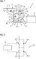
- FIG. 1 shows the implementation of the half-bridge circuit 34h of the high subunit 28h.
- This has two transistors, in particular each in the form of an IGBT (Insulated Gate Bipolar Transistor), which form the controllable switching elements 32h.1 and 32h.2.
- IGBT Insulated Gate Bipolar Transistor
- a diode 44h.1 or 44h.2 is connected in parallel to the switching elements.
- FIG Figure 1 The consumer 25 of the rail vehicle 10 that can be supplied with energy by the circuit 18 is shown in FIG Figure 1 shown schematically.
- this can be a traction system.
- this has a power supply unit which, based on the provided direct voltage V C , is used to generate an electrical current, in particular three-phase current, the properties of which are set in accordance with a traction power to be generated.
- the power supply unit can be designed as a traction converter.
- Figure 3 shows the design of the half-bridge circuit 34t of the deep subunit 28t with this design of the consumer 25 as a traction system. It is designed identically to the half-bridge circuit 34h and has two transistors, in particular each in the form of an IGBT (Insulated Gate Bipolar Transistor), which form the controllable switching elements 32t.1 and 32t.2. A diode 44t.1 or 44t.2 is connected in parallel to the switching elements.
- IGBT Insulated Gate Bipolar Transistor
- a consumer 25 that can be supplied by the circuit 18 can be an on-board electrical system supply. As is known, this has a converter at its input.
- An embodiment of the half-bridge circuit 34t of the deep subunit 28t adapted to this consumer 25 can - in contrast to the embodiment according to FIG Figure 3 - correspond to a simple series connection of two diodes.
- the Figures 4 to 6 each show an alternative embodiment of the circuit 18.
- the circuit 18, in particular the voltage conversion unit 26 has a means 46 which, with the element 38 of the charge transfer unit 36, defines a resonance frequency.
- the means 46 is in the embodiments according to FIG Figures 4 to 6 designed as one or more inductors.
- the control unit 42 is provided to control the switching unit 40, in particular its switching elements 32h.1 and 32h.2, with this resonance frequency. Thus, these switching elements can be switched with the lowest possible currents.
- the switching unit 40 is operated quasi-resonantly.
- the switching element 32h.1 is closed in particular in a currentless phase and opened again in the next currentless phase after a half-wave. A short subsequent delay time can have the effect that charges are removed from the switching elements. The same process then takes place for the switching element 32h.2.
- the means 46 is connected in series with the element 38 so that it is between the bridge circuits 34h and 34t, in particular are arranged between the bridge centers.
- the components of the circuit 18 have the following values: charge storage 30h and 30t each 500 ⁇ F; Element 38: 250 ⁇ F; Medium 46: 12 ⁇ H.
- Figure 5 shows an alternative embodiment with an embodiment of the means 46 with two elements 48 and 50, which in particular are each designed as an inductance. Both elements 48, 50 are connected to the terminals of the charge store 30t of the deep subunit 28t directly and in such a way that they are arranged between this charge store 30t and the consumer 25. The output terminals of these elements 48, 50 accordingly form the consumer side 24 of the circuit 18. The connection to the high subunit 28h is also branched off between the element 48 and the consumer 25.
- the training according to Figure 6 differs from the previous explanations in that the means 46 connects the high and low subunits 28h, 28t directly in series with one another.
- the circuit 18 in the embodiments according to FIGS Figures 1 and 4 to 6 a voltage conversion unit 26 which provides a voltage V C on the consumer side 24 which corresponds to half the mains voltage V N.
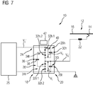
- Figure 7 shows the circuit 18 in a variant in which a voltage conversion unit 26 'is used to provide a voltage V C ' on the consumer side 24, which corresponds to twice the mains voltage V N '.
- this mains voltage V N ' is preferably 750V DC and the voltage V C ' provided by the voltage conversion unit 26 'is 1.5kV DC.
- the structure of the voltage conversion unit 26 ′ corresponds to that of the voltage conversion unit 26, with the input side 20 and the consumer side 24 being interchanged with one another compared to the above explanations.
- the reference symbols for the components of the Voltage conversion unit 26 ' are retained and the control of voltage conversion unit 26' takes place as in the above exemplary embodiments.
- the electrical current drawn from the mains supply 12 is fed into the circuit 18 at a point which is arranged between the subunits 28h and 28t.
- the potentials V h and V t of the subunits 28h, 28t are identical and each amount to the line voltage V N of 750V, ie half of the voltage V C provided on the consumer side 24.
- the principle of the invention has been explained in the drawings for an electrical phase.
- the circuit 18 can be constructed in multiple phases, in particular with a synchronous phase shift.
- the circuit is designed for 3 or 6-phase operation.
- a structurally simple design can be achieved with a design for 2-phase operation.
Landscapes
- Engineering & Computer Science (AREA)
- Power Engineering (AREA)
- Life Sciences & Earth Sciences (AREA)
- Sustainable Development (AREA)
- Sustainable Energy (AREA)
- Transportation (AREA)
- Mechanical Engineering (AREA)
- Dc-Dc Converters (AREA)
- Electric Propulsion And Braking For Vehicles (AREA)
- Rectifiers (AREA)
Description
- Die Erfindung betrifft ein Schienenfahrzeug umfassend eine Schaltung, welches im Betrieb durch eine Netzversorgung mit elektrischer Energie speisbar ist, mit einer Eingangsseite, die dazu vorbereitet ist, eine von der Netzversorgung bereitgestellte Netzspannung zu führen, und einer Verbraucherseite, die zumindest einem Fahrzeugverbraucher zugeordnet ist. Das Dokument
JP 2010 063267 A - Zur Speisung von elektrischen Fahrzeugen, die im Betrieb eine elektrische Energie aus einer externen Versorgung beziehen, bestehen Versorgungsnetze, die historisch bedingt und insbesondere länderspezifisch unterschiedliche Netzspannungen bereitstellen. Diese verschiedenen Netzspannungen erfordern auf der Fahrzeugseite jeweils eine spezifische, an die entsprechende Netzspannung angepasste Ausrüstung. Bezüglich der heutzutage eingesetzten Elemente der Leistungselektronik können sich die Ausrüstungen in der Dimensionierung dieser Elemente voneinander stark unterscheiden. Diese Situation ist bezüglich von Standardisierungsbemühungen auf der Verbraucherseite nachteilhaft. Diese Problematik betrifft insbesondere elektrische Schienenfahrzeuge, deren Ausrüstung im Hinblick auf die verschiedenen, nationalen Erfordernisse auszulegen ist. Insbesondere für einen Betrieb von Schienenfahrzeugen unter einer Versorgungsspannung von 3kV DC müssen Elemente der Leistungselektronik speziell für diesen Anwendungsfall ausgelegt werden. Der Einsatz von Elementen, die im Industriebereich weit verbreitet sind, ist ohne Weiteres nicht möglich.
- Der Erfindung liegt die Aufgabe zugrunde, ein Schienenfahrzeug mit einer derartigen Schaltung bereitzustellen, durch welche diese Nachteile in einer konstruktiv einfachen Weise vermindert, insbesondere verhindert werden können.
- Hierzu wird vorgeschlagen, dass die Schaltung eine Spannungswandlungseinheit zur Bereitstellung einer für den Betrieb des elektrischen Fahrzeugverbrauchers angepassten Spannung an der Verbraucherseite umfasst, die eine erste, der Eingangsseite zugeordnete, im Betrieb unter einem Potential stehende Teileinheit, zumindest eine zweite, der Verbraucherseite zugeordnete, im Betrieb unter einem Potential stehende Teileinheit und eine Ladungsübertragungseinheit aufweist, die dazu vorgesehen ist, eine Ladung von der ersten Teileinheit zur zweiten Teileinheit zu übertragen. Hierdurch kann auf eine konstruktiv einfache Weise auf der Verbraucherseite eine gegenüber der Netzspannung reduzierte oder erhöhte Spannung bereitgestellt werden, wodurch in der Auslegung der elektrischen Anlage des Fahrzeugs eine vorteilhafte, zumindest teilweise Unabhängigkeit vom Wert der Netzspannung erreicht werden kann. Bei einer Spannungsreduktion können insbesondere durch den Wert der Netzspannung bedingte konstruktions- und kostenaufwändige Maßnahmen eingespart werden.
- Die Ladungsübertragungseinheit kann zweckmäßigerweise abwechselnd mit den Teileinheiten derart verbunden werden, dass das Potential, unter welchem eine von der Ladungsübertragungseinheit aufgenommene Ladung steht, vor der Übertragung dem Potential der ersten Teileinheit und nach der Übertragung dem Potential der zweiten Teileinheit entspricht.
- Die Erfindung eignet sich insbesondere für einen elektrischen Fahrzeugverbraucher, welcher als Traktionsanlage ausgebildet ist. Dabei dient die Schaltung insbesondere dazu, eine elektrische Spannung bereitzustellen, aus welcher zumindest eine Leistungsversorgungseinheit der Traktionsanlage, z.B. ein Traktionsumrichter, einen elektrischen Strom, insbesondere einen Drehstrom, gemäß einer zu erzeugenden Traktionsleistung erzeugt. Der Fahrzeugverbraucher kann ferner als Bordnetzversorgung ausgebildet sein.
- Die Erfindung eignet sich für einen Einsatz bei einer als Gleichspannung ausgebildeten Netzspannung, da die oben erwähnten Maßnahmen zur Zuführung dieser Spannung zum Verbraucher herkömmlicherweise - besonders bei einer Netzspannung in Höhe von 3 kV DC - besonders aufwendig sein können. Es ist daher vorteilhaft, wenn die Eingangsseite dazu vorbereitet ist, eine von der Netzversorgung bereitgestellte, als Gleichspannung ausgebildete Netzspannung zu führen. Die Schaltung hat zweckmäßigerweise die Funktion eines Tiefsetzstellers bzw. Hochsetzstellers als Einspeiseschaltung des Schienenfahrzeugs. Im Vergleich zu einem konventionellen Tiefsetzteller bzw. Hochsetzsteller kann durch die Erfindung eine besonders konstruktiv einfache Ausführung dieser Funktion erreicht werden. Insbesondere kann die Dimensionierung der passiven und aktiven Bauteile signifikativ reduziert werden. Es kann insbesondere gegenüber einem klassischen Einsatz eines Choppers ein kleiner und leichter Aufbau der Schaltung erreicht werden.
- Eine Vereinheitlichung in der Ausführung der elektrischen Anlage von unter Gleichspannung betreibbaren Fahrzeugen kann außerdem zumindest angestrebt werden, da eine Abhängigkeit vom Wert der Netzspannung durch die Erfindung erheblich vermindert werden kann. Insbesondere kann eine für einen Betrieb unter einer gegebenen verbraucherseitigen Spannung angepasste Auslegung der elektrischen Anlage vorteilhafterweise bei einer Netzspannung, die der doppelten und/oder der halben verbraucherseitigen Spannung entspricht, ohne aufwendige Anpassungen benutzt werden, wenn die Spannungswandlungseinheit dazu vorgesehen ist, eine Spannung an der Verbraucherseite bereitzustellen, die der halben oder doppelten Netzspannung entspricht. Bezüglich einer Ausbildung des Fahrzeugverbrauchers als Traktionsanlage kann eine erhöhte Flexibilität in der Anwendung einer Traktionsanlage erreicht werden, ohne dass aufwendige Anpassungen an Elementen derselben, insbesondere der Leistungselektronik und der Antriebsmotoren, notwendig sind. Eine für einen Betrieb unter 1,5kV DC angepasste Auslegung einer Traktionsanlage und/oder einer Bordnetzversorgung kann vorteilhafterweise bei einer Netzspannung von 3kV DC und/oder 750 V DC ohne aufwendige Anpassungen benutzt werden. Bei einer Netzspannung von 3kV DC können außerdem durch eine Halbierung Elemente für die Leistungselektronik eingesetzt werden, die im Industriebereich weit verbreitet sind. Eine kostenaufwendige Konstruktion einer Leistungselektronik speziell für diesen Anwendungsfall kann demnach entfallen. Insbesondere können für eine Leistungselektronik anstatt von Hochvolt-IGBTs, die z.B. zu einem Betrieb unter einer Spannung von 6,5kV vorgesehen sind, niedersperrende IGBTs eingesetzt werden, die sich durch eine höhere Schaltfrequenz, eine hohe Verfügbarkeit und niedrigere Preise kennzeichnen.
- Die Ladungsübertragungseinheit weist zumindest ein Element, welches einem Paar von Teileinheiten zugeordnet ist, und eine Schalteinheit auf, die dazu vorgesehen ist, das Element zwischen den Teileinheiten zyklisch umzuschalten. Hierdurch kann zur Ladungsübertragung ein besonders geringer Schaltungsaufwand erreicht werden. Unter einem Umschalten des Elements der Ladungsübertragungseinheit "zwischen den Teileinheiten" soll verstanden werden, dass die Klemmen des Elements zyklisch mit der ersten Teileinheit und der zweiten Teileinheit des dem Element zugeordneten Paars derart verbunden werden, dass das Element unter dem Potential der ersten Teileinheit des Paares und dem Potential der zweiten Teileinheit des Paares zyklusgemäß und daher zeitlich nacheinander steht. Das Element ist zweckmäßigerweise als Ladungsspeicherelement ausgebildet.
- Das Paar ist von der ersten Teileinheit und der zweiten Teileinheit der Schaltung gebildet. Insbesondere ist eine Ausführung der Ladungsübertragungseinheit mit lediglich einem umschaltbaren Element möglich. Außerdem führt vorzugsweise zumindest ein Teil der ersten Teileinheit die Netzspannung, während zumindest ein Teil der zweiten Teileinheit vorzugsweise die an der Verbraucherseite bereitgestellte Spannung führt. Insbesondere kann der Teil der ersten Teileinheit die Eingangsseite der Schaltung bilden, während der Teil der zweiten Teileinheit einen Ausgang der Schaltung auf der Verbraucherseite bilden kann.
- Gemäß einer bevorzugten Ausführung der Erfindung ist das zumindest ein Element der Ladungsübertragungseinheit als Kondensator ausgebildet, wodurch der Einsatz eines kompakten, einfach ausgeführten, und mit niedrigen Verlusten behafteten passiven Bauteils erreicht werden kann.
- Es können außerdem gängige, kostengünstige Elemente einer Leistungselektronik zur Bildung der Spannungswandlungseinheit eingesetzt werden, wenn die Teileinheiten jeweils eine Halbbrückenschaltung aufweisen und das zumindest ein Element zwischen den Brückenmittelpunkten der Halbbrückenschaltungen geschaltet ist, wobei die Schalteinheit zumindest von steuerbaren Schaltelementen einer Halbbrückenschaltung gebildet ist. Die steuerbaren Schaltelemente entsprechen zweckmäßigerweise üblichen Schaltventilen einer Leistungselektronik. Ferner kann die Schalteinheit von steuerbaren Schaltelementen der der Eingangsseite zugeordneten Halbbrückenschaltung gebildet sein.
- Eine kompakte Ausgestaltung der Spannungswandlungseinheit kann außerdem dadurch erreicht werden, dass die Schaltung eine Steuereinheit zur Steuerung der Schalteinheit aufweist, die dazu vorgesehen ist, die Schalteinheit mit einer Frequenz von zumindest 1 kHz zu betreiben. Insbesondere kann dadurch eine Ausführung der Ladungsübertragungseinheit erzielt werden, welche einen kleinen Bauraum in Anspruch nimmt, da das umschaltbare Element kompakt ausgeführt sein kann. Ist dieses als Kondensator ausgebildet, kann dieser vorteilhaft klein dimensioniert werden.
- Die zyklische Umschaltung durch die Schalteinheit erfolgt gemäß einem vordefinierten Tastgrad. Die Schaltung weist ein Mittel, welches mit dem zumindest einen Element der Ladungsübertragungseinheit eine Resonanzfrequenz definiert, und eine Steuereinheit zur Steuerung der Schalteinheit auf, die dazu vorgesehen ist, die Schalteinheit mit der Resonanzfrequenz zu betreiben. Hierdurch können Schaltvorgänge der Schalteinheit vorteilhaft in möglichst stromlosen Phasen erfolgen. Vorzugsweise weist die Schalteinheit steuerbare Schaltelemente auf, die zweckmäßigerweise üblichen Schaltventilen einer Leistungselektronik entsprechen. Die Umschaltung erfolgt dabei vorzugsweise über eine quasiresonante Steuerung der Schaltventile, d.h. die Schaltvorgänge der Schaltventile erfolgen in möglichst stromlosen Phasen. Dadurch können Schaltverluste der Schaltventile signifikativ reduziert werden.
- Es werden Ausführungsbeispiele der Erfindung anhand der Zeichnungen erläutert. Es zeigen:
- Figur 1:
- eine Netzversorgung und ein Schienenfahrzeug mit einer Schaltung und einem elektrischen Verbraucher, wobei die Schaltung zur Halbierung der Netzversorgungspannung vorgesehen ist,
- Figur 2:
- eine Brückenschaltung der Schaltung,
- Figur 3:
- eine weitere Brückenschaltung der Schaltung,
- Figuren 4 bis 6:
- alternative Ausführungen der Schaltung aus
Figur 1 und - Figur 7:
- eine alternative Ausführung der Schaltung aus
Figur 1 , wobei die Schaltung zur Verdopplung der Netzversorgungspannung vorgesehen ist. -
Figur 1 zeigt ein als Schienenfahrzeug 10 ausgebildetes Fahrzeug in einer stark schematisierten Ansicht. Dieses ist als Elektrofahrzeug ausgebildet, welches für dessen Betrieb und insbesondere in einem Traktionsbetrieb eine elektrische Energie aus einer Netzversorgung 12 bezieht. Die Netzversorgung 12 stellt eine Netzspannung VN bereit, die eine Gleichspannung in Höhe von 3 kV ist. Diese Netzspannung VN wird von einer Spannungserfassungseinheit 14 erfasst und wird in eine elektrische Anlage des Schienenfahrzeuges 10 eingespeist. In der fachmännischen Sprache ist die Spannungserfassungseinheit 14 auch "Stromabnehmer" genannt. In der betrachteten Ausführung wird die Netzspannung VN von einer als Oberleitung ausgebildeten netzseitigen Versorgungsleitung 16 bereitgestellt, wobei die Spannungserfassungseinheit 14 auf dem Dach des Schienenfahrzeugs 10 und insbesondere als Pantograph ausgebildet ist. In einer Ausführungsvariante kann die netzseitige Versorgungsleitung 16 als Stromschiene ausgebildet sein, die insbesondere im Gleisbettbereich angeordnet ist. - Die elektrische Anlage des Schienenfahrzeugs 10 umfasst eine Schaltung 18, die als sogenannte Einspeiseschaltung dient. Die Einspeiseschaltung 18 weist dabei eine Eingangsseite 20 auf, die mit der Spannungserfassungseinheit 14 elektrisch verbindbar ist und dazu vorbereitet ist, die Netzspannung VN zu führen. In der betrachteten Ausführung ist eine Induktivität 22 zwischen der Eingangsseite 20 und der Spannungserfassungseinheit 14 angeordnet. Außerdem ist ein in der Figur nicht näher dargestellter Hauptschalter zwischen der Spannungserfassungseinheit 14 und der Eingangsseite 20 angeordnet. Die Schaltung 18 weist des Weiteren eine der Eingangsseite 20 abgewandte Verbraucherseite 24 auf, die zumindest einem Verbraucher 25 des Schienenfahrzeugs 10 zugeordnet ist.
- Die Schaltung 18 umfasst eine Spannungswandlungseinheit 26, die dazu vorgesehen ist, eine für den Betrieb des Fahrzeugverbrauchers 25 angepasste Spannung VC bereitzustellen. Diese Spannung VC wird wie unten näher dargestellt an der Verbraucherseite 24 der Schaltung 18 bereitgestellt.
- Zur Umwandlung der Netzspannung VN weist die Spannungswandlungseinheit 26 eine erste Teileinheit 28h und eine zweite Teileinheit 28t auf. Die Teileinheiten weisen jeweils einen Ladungsspeicher 30h bzw. 30t und ein Paar von Schaltelementen 32h.1, 32h.2 bzw. 32t.1, 32t.2 auf, das zum jeweiligen Ladungsspeicher 30h bzw. 30t parallel geschaltet ist. Die Paare von Schaltelementen sind jeweils Bestandteil einer Halbbrückenschaltung 34h bzw. 34t, wobei die Halbbrückenschaltungen 34h und 34t in Reihe zueinander geschaltet sind. Die erste Teileinheit 28h mit der Halbbrückenschaltung 34h ist der Eingangsseite 20 zugeordnet. Insbesondere führt im Betrieb zumindest ein die Eingangsseite 20 bildender Teil der Teileinheit 28h die Netzspannung VN. Die zweite Teileinheit 28t mit der Halbbrückenschaltung 34t ist der Verbraucherseite 24 zugeordnet, wobei zumindest ein die Verbraucherseite 24 bildender Teil der Teileinheit 28t im Betrieb die für den Betrieb des Fahrzeugverbrauchers 25 angepasste Spannung VC führt. Die Teileinheiten 28h und 28t werden im folgenden Text "hohe" bzw. "tiefe" Teileinheiten genannt.
- Die Schaltung 18 weist zur Ladungsübertragung von der hohen Teileinheit 28h in die tiefe Teileinheit 28t eine Ladungsübertragungseinheit 36 mit einem als Kondensator ausgebildeten Element 38 auf. Dieses Element 38 ist dem von der hohen Teileinheit 28h und der tiefen Teileinheit 28t gebildeten Paar von Teileinheiten zugeordnet und wird zwischen den jeweiligen Potentialen Vh, Vt der Teileinheiten 28h und 28t zyklisch umgeschaltet. Das Element 38 ist schaltungstechnisch derart angeordnet, dass es die Brückenmittelpunkte der Halbbrückenschaltungen 34h, 34t miteinander verbindet. Somit ist es zwischen den Brückenmittelpunkten geschaltet, wobei diese jeweils zwischen zwei Schaltelementen 32h.1, 32h.2 bzw. 32t.1, 32t.2 der jeweiligen Halbbrückenschaltung 34h bzw. 34t angeordnet sind. Zumindest die Schaltelemente 32h.1, 32h.2 werden derart in ihrem Schaltbetrieb gesteuert, dass das Element 38 zyklisch zwischen den jeweiligen Potentialen Vh, Vt der hohen und der tiefen Teileinheit 28h, 28t umgeschaltet wird. Die Schaltelemente 32h.1, 32h.2 der Halbbrückenschaltung 34h sind demnach Bestandteile einer Schalteinheit 40, die dazu dient, das Element 38 zwischen den jeweiligen Potentialen Vh, Vt der Teileinheiten 28h und 28t zyklisch umzuschalten. Die der Halbbrückenschaltung 34h zugeordnete, in der Figur schematisch dargestellte Steuereinheit dient dabei als Steuereinheit 42 für die Schalteinheit 40. Sie ist für einen Schaltbetrieb der Schaltelemente 32h.1, 32h.2 programmiert, bei welchem diese mit einem Tastgrad von 50% und mit einer Frequenz von zumindest 1 kHz geschaltet werden. Die Halbbrückenschaltung 34t der tiefen Teileinheit 28t dient dazu, das erzeugte Spannungssignal gleich zu richten, sodass die an der Verbraucherseite 24 bereitgestellte Spannung VC eine Gleichspannung ist.
- In der in
Figur 1 betrachteten Ausführung sowie in den Ausführungen gemäß denFiguren 4 bis 6 wird durch die Schaltung 18 ausgehend von der Netzspannung VN von 3kV die Spannung VC in Höhe von 1,5kV bereitgestellt. Die Netzspannung VN wird demnach mittels der Spannungswandlungseinheit 26 halbiert. Die Potentiale Vh und Vt der Teileinheiten 28h, 28t sind dabei identisch und entsprechen jeweils der Hälfte der Netzspannung VN, d.h. entsprechen auch der an der Verbraucherseite 24 bereitgestellten Spannung VC in Höhe von 1,5kV. -
Figur 2 zeigt die Ausführung der Halbbrückenschaltung 34h der hohen Teileinheit 28h. Diese weist zwei Transistoren, insbesondere jeweils in der Form eines IGBTs (Insulated Gate Bipolar Transistor) auf, welche die steuerbaren Schaltelemente 32h.1 und 32h.2 bilden. Parallel zu den Schaltelementen ist jeweils eine Diode 44h.1 bzw. 44h.2 geschaltet. - Der von der Schaltung 18 mit Energie versorgbare Verbraucher 25 des Schienenfahrzeugs 10 ist in
Figur 1 schematisch dargestellt. In einer ersten Ausführung kann dieser eine Traktionsanlage sein. Diese weist bekannterweise eine Leistungsversorgungseinheit auf, die dazu dient, ausgehend von der bereitgestellten Gleichspannung VC einen elektrischen Strom, insbesondere Drehstrom, zu erzeugen, dessen Eigenschaften gemäß einer zu erzeugenden Traktionsleistung eingestellt werden. Die Leistungsversorgungseinheit kann als Traktionsstromrichter ausgebildet sein. -
Figur 3 zeigt die Ausführung der Halbbrückenschaltung 34t der tiefen Teileinheit 28t bei dieser Ausbildung des Verbrauchers 25 als Traktionsanlage. Sie ist identisch zur Halbbrückenschaltung 34h ausgebildet und weist zwei Transistoren, insbesondere jeweils in der Form eines IGBTs (Insulated Gate Bipolar Transistor) auf, welche die steuerbaren Schaltelemente 32t.1 und 32t.2 bilden. Parallel zu den Schaltelementen ist jeweils eine Diode 44t.1 bzw. 44t.2 geschaltet. - In einer weiteren Ausführung kann ein von der Schaltung 18 versorgbarer Verbraucher 25 eine elektrische Bordnetzversorgung sein. Dieses weist an dessen Eingang bekannterweise einen Umrichter auf. Eine an diesen Verbraucher 25 angepasste Ausführung der Halbbrückenschaltung 34t der tiefen Teileinheit 28t kann - anders als in der Ausführung gemäß
Figur 3 - einer einfachen Reihenschaltung von zwei Dioden entsprechen. - Die
Figuren 4 bis 6 zeigen jeweils eine alternative Ausführung der Schaltung 18. Um unnötige Wiederholungen zu vermeiden werden lediglich die Unterschiede zur Ausführung gemäßFigur 1 beschrieben. In den gezeigten Ausbildungen gemäß Figur 4 bis 6 weist die Schaltung 18, insbesondere die Spannungswandlungseinheit 26 ein Mittel 46 auf, welches mit dem Element 38 der Ladungsübertragungseinheit 36 eine Resonanzfrequenz definiert. Insbesondere ist das Mittel 46 in den Ausbildungen gemäßFigur 4 bis 6 als eine oder mehrere Induktivitäten ausgebildet. Die Steuereinheit 42 ist dabei dazu vorgesehen, die Schalteinheit 40, insbesondere deren Schaltelemente 32h.1 und 32h.2 mit dieser Resonanzfrequenz zu steuern. Somit können diese Schaltelemente bei möglichst niedrigen Strömen geschaltet werden. Die Schalteinheit 40 wird dabei quasiresonant betrieben. Das Schaltelement 32h.1 wird insbesondere in einer stromlosen Phase geschlossen und in der nächsten stromlosen Phase nach einer Halbwelle wieder geöffnet. Eine kurze nachfolgende Verzögerungszeit kann dazu wirken, dass Ladungen aus den Schaltelementen entfernt werden. Der gleiche Vorgang erfolgt dann anschließend für das Schaltelement 32h.2. - In der Ausführung gemäß
Figur 4 ist das Mittel 46 in Reihe mit dem Element 38 geschaltet, sodass diese zwischen den Brückenschaltungen 34h und 34t, insbesondere zwischen den Brückenmittelpunkten angeordnet sind. - In einer beispielhaften Auslegung weisen die Komponenten der Schaltung 18 folgende Werte auf: Ladungsspeicher 30h und 30t jeweils 500µF; Element 38: 250µF; Mittel 46: 12µH.
-
Figur 5 zeigt eine Alternative Ausbildung mit einer Ausführung des Mittels 46 mit zwei Elementen 48 und 50, die insbesondere jeweils als Induktivität ausgebildet sind. Beide Elemente 48, 50 sind mit den Klemmen des Ladungsspeichers 30t der tiefen Teileinheit 28t direkt und derart verbunden, dass sie zwischen diesem Ladungsspeicher 30t und dem Verbraucher 25 angeordnet sind. Die Ausgangsklemmen dieser Elemente 48, 50 bilden demnach die Verbraucherseite 24 der Schaltung 18. Zwischen dem Element 48 und dem Verbraucher 25 ist ferner die Verbindung zur hohen Teileinheit 28h abgezweigt. - Die Ausbildung gemäß
Figur 6 unterscheidet sich von den vorherigen Ausführungen dadurch, dass das Mittel 46 die hohe und tiefe Teileinheit 28h, 28t direkt in Reihe miteinander verbindet. - Wie oben bereits erwähnt weist die Schaltung 18 in den Ausführungen gemäß den
Figuren 1 und4 bis 6 eine Spannungswandlungseinheit 26 auf, die an der Verbraucherseite 24 eine Spannung VC bereitstellt, die der halben Netzspannung VN entspricht.Figur 7 zeigt die Schaltung 18 in einer Ausführungsvariante, bei welcher eine Spannungswandlungseinheit 26' dazu dient, eine Spannung VC' an der Verbraucherseite 24 bereitzustellen, die der doppelten Netzspannung VN' entspricht. In dieser Ausführung betragen diese Netzspannung VN' vorzugsweise 750V DC und die von der Spannungsumwandlungseinheit 26' bereitgestellte Spannung VC' 1,5kV DC. Der Aufbau der Spannungsumwandlungseinheit 26' entspricht dem der Spannungsumwandlungseinheit 26, wobei gegenüber den obigen Ausführungen die Eingangsseite 20 und die Verbraucherseite 24 miteinander vertauscht werden. Die Bezugszeichen für die Komponenten der Spannungsumwandlungseinheit 26' werden beibehalten und die Steuerung der Spannungsumwandlungseinheit 26' erfolgt wie in den obigen Ausführungsbeispielen. Der von der Netzversorgung 12 bezogene elektrische Strom wird in die Schaltung 18 an einem Punkt eingespeist, welcher zwischen den Teileinheiten 28h und 28t angeordnet ist. Die Potentiale Vh und Vt der Teileinheiten 28h, 28t sind dabei identisch und betragen jeweils die Netzspannung VN in Höhe von 750V, d.h. die Hälfte der an der Verbraucherseite 24 bereitgestellten Spannung VC. - Das Prinzip der Erfindung wurde in den Zeichnungen für eine elektrische Phase erklärt. Die Schaltung 18 kann mehrphasig, insbesondere mit synchroner Phasenverschiebung aufgebaut werden. Idealerweise ist die Schaltung für einen 3- oder 6-phasigen Betrieb ausgelegt. Eine konstruktive einfache Ausgestaltung kann bei einer Auslegung für einen 2-phasigen Betrieb erreicht werden.
Claims (7)
- Schienenfahrzeug, mit einer Spannungserfassungseinheit (14) zum Erfassen einer von einer Netzversorgung (12) bereitgestellten als Gleichspannung ausgebildeten Netzspannung (VN), zumindest einem elektrischen Verbraucher (25) und einer Schaltung (18), die zur Versorgung des elektrischen Verbrauchers (25) im Betrieb eine elektrische Energie von der Netzversorgung (12) bezieht, die Schaltung umfassend eine Spannungswandlungseinheit (26) zur Bereitstellung einer für den Betrieb des Verbrauchers (25) angepassten Spannung (VC) an der Verbraucherseite (24), die eine erste, der Eingangsseite (20) zugeordnete, im Betrieb unter einem Potential (Vh) stehende Teileinheit (28h), zumindest eine zweite, der Verbraucherseite (24) zugeordnete, im Betrieb unter einem Potential (Vt) stehende Teileinheit (28t) und eine Ladungsübertragungseinheit (36) aufweist, die dazu vorgesehen ist, eine Ladung von der ersten Teileinheit (28h) zur zweiten Teileinheit (28t) zu übertragen,
wobei die Ladungsübertragungseinheit (36) zumindest ein Element (38), welches den Teileinheiten (28h, 28t) zugeordnet ist, und eine Schalteinheit (40) aufweist, die dazu vorgesehen ist, das zumindest eine Element (38) zwischen den Teileinheiten (28h, 28t) zyklisch umzuschalten,
ein Mittel (46), welches mit dem zumindest einen Element (38) eine Resonanzfrequenz definiert, und
eine Steuereinheit (42) zur Steuerung der Schalteinheit (40), die dazu vorgesehen ist, die Schalteinheit (40) mit der Resonanzfrequenz zu betreiben. - Schienenfahrzeug nach Anspruch 1,
dadurch gekennzeichnet, dass
der elektrische Verbraucher (25) als Traktionsanlage ausgebildet ist. - Schienenfahrzeug nach Anspruch 1 oder 2,
dadurch gekennzeichnet, dass
der elektrische Verbraucher (25) als Bordnetzversorgung ausgebildet ist. - Schienenfahrzeug nach einem der vorhergehenden Ansprüche 1 bis 3,
dadurch gekennzeichnet, dass
das zumindest eine Element (38) als Kondensator ausgebildet ist. - Schienenfahrzeug nach einem der vorhergehenden Ansprüche,
dadurch gekennzeichnet, dass
die Teileinheiten (28h, 28t) jeweils eine Halbbrückenschaltung (34h, 34t) aufweisen und das zumindest ein Element (38) zwischen den Brückenmittelpunkten der Halbbrückenschaltungen (34h, 34t) geschaltet ist, wobei die Schalteinheit (42) zumindest von steuerbaren Schaltelementen (32h.1, 32h.2) einer Halbbrückenschaltung (34h) gebildet ist. - Schienenfahrzeug nach einem der vorhergehenden Ansprüche,
gekennzeichnet durch
eine Steuereinheit (42) zur Steuerung der Schalteinheit (40), die dazu vorgesehen ist, die Schalteinheit (40) mit einer Frequenz von zumindest 1 kHz zu betreiben. - Schienenfahrzeug nach einem der vorhergehenden Ansprüche,
dadurch gekennzeichnet, dass
die Spannungswandlungseinheit (26) dazu vorgesehen ist, eine Spannung (VC) an der Verbraucherseite (24) bereitzustellen, die der halben oder doppelten Netzspannung entspricht.
Priority Applications (1)
| Application Number | Priority Date | Filing Date | Title |
|---|---|---|---|
| PL15728469T PL3129254T3 (pl) | 2014-06-06 | 2015-06-03 | Pojazd szynowy zawierający obwód |
Applications Claiming Priority (2)
| Application Number | Priority Date | Filing Date | Title |
|---|---|---|---|
| DE102014210898.5A DE102014210898A1 (de) | 2014-06-06 | 2014-06-06 | Schaltung für ein Fahrzeug, insbesondere ein Schienenfahrzeug |
| PCT/EP2015/062321 WO2015185588A1 (de) | 2014-06-06 | 2015-06-03 | Schaltung für ein fahrzeug, insbesondere ein schienenfahrzeug |
Publications (2)
| Publication Number | Publication Date |
|---|---|
| EP3129254A1 EP3129254A1 (de) | 2017-02-15 |
| EP3129254B1 true EP3129254B1 (de) | 2021-07-28 |
Family
ID=53385613
Family Applications (1)
| Application Number | Title | Priority Date | Filing Date |
|---|---|---|---|
| EP15728469.6A Active EP3129254B1 (de) | 2014-06-06 | 2015-06-03 | Schienenfahrzeug umfassend eine schaltung |
Country Status (6)
| Country | Link |
|---|---|
| EP (1) | EP3129254B1 (de) |
| DE (1) | DE102014210898A1 (de) |
| ES (1) | ES2895624T3 (de) |
| PL (1) | PL3129254T3 (de) |
| RU (1) | RU2658225C2 (de) |
| WO (1) | WO2015185588A1 (de) |
Families Citing this family (1)
| Publication number | Priority date | Publication date | Assignee | Title |
|---|---|---|---|---|
| CN114514680A (zh) * | 2020-09-14 | 2022-05-17 | 华为技术有限公司 | Dc/dc功率转换器、用于控制dc/dc功率转换器的切换的方法、dc/dc功率转换器布置、以及系统 |
Family Cites Families (13)
| Publication number | Priority date | Publication date | Assignee | Title |
|---|---|---|---|---|
| JPH05244766A (ja) * | 1992-02-27 | 1993-09-21 | Texas Instr Japan Ltd | チャージポンプ回路 |
| JPH09312968A (ja) * | 1996-05-22 | 1997-12-02 | Nec Corp | チャージポンプ回路 |
| RU2167071C1 (ru) * | 2000-09-21 | 2001-05-20 | Федеральное государственное унитарное предприятие "Центральный научно-исследовательский институт судовой электротехники и технологии" | Устройство преобразования электрической энергии |
| US7719343B2 (en) * | 2003-09-08 | 2010-05-18 | Peregrine Semiconductor Corporation | Low noise charge pump method and apparatus |
| EP1562279A3 (de) * | 2004-02-06 | 2005-11-02 | HONDA MOTOR CO., Ltd. | DC-DC-Wandler und Programm |
| US7301400B1 (en) * | 2004-06-02 | 2007-11-27 | Rf Micro Devices, Inc. | Multi-phase switching power supply for mobile telephone applications |
| JP2007244078A (ja) * | 2006-03-07 | 2007-09-20 | Rohm Co Ltd | スイッチング電源装置およびその駆動回路、ならびにそれらを用いた電子機器 |
| CN101309048A (zh) * | 2007-05-17 | 2008-11-19 | 比亚迪股份有限公司 | 一种电荷泵装置及电源电路 |
| JP2010063267A (ja) * | 2008-09-03 | 2010-03-18 | Denso Corp | 電源装置 |
| WO2012074967A1 (en) * | 2010-11-29 | 2012-06-07 | President And Fellows Of Harvard College | Fully integrated 3-level dc/dc converter for nanosecond-scale dynamic voltage scaling with fast shunt regulation |
| US8680795B2 (en) * | 2011-06-03 | 2014-03-25 | Ford Global Technologies, Llc | Vehicle electric drive and power systems |
| US20140001856A1 (en) * | 2012-06-29 | 2014-01-02 | General Electric Company | Multilevel power converter |
| DE102012216691A1 (de) * | 2012-09-18 | 2014-03-20 | Bombardier Transportation Gmbh | Stromrichterschaltung und Verfahren zur Steuerung der Stromrichterschaltung |
-
2014
- 2014-06-06 DE DE102014210898.5A patent/DE102014210898A1/de not_active Ceased
-
2015
- 2015-06-03 WO PCT/EP2015/062321 patent/WO2015185588A1/de not_active Ceased
- 2015-06-03 RU RU2016147714A patent/RU2658225C2/ru active
- 2015-06-03 EP EP15728469.6A patent/EP3129254B1/de active Active
- 2015-06-03 ES ES15728469T patent/ES2895624T3/es active Active
- 2015-06-03 PL PL15728469T patent/PL3129254T3/pl unknown
Non-Patent Citations (1)
| Title |
|---|
| None * |
Also Published As
| Publication number | Publication date |
|---|---|
| RU2016147714A (ru) | 2018-06-06 |
| RU2658225C2 (ru) | 2018-06-19 |
| PL3129254T3 (pl) | 2022-01-10 |
| DE102014210898A1 (de) | 2015-12-17 |
| WO2015185588A1 (de) | 2015-12-10 |
| RU2016147714A3 (de) | 2018-06-06 |
| EP3129254A1 (de) | 2017-02-15 |
| ES2895624T3 (es) | 2022-02-22 |
Similar Documents
| Publication | Publication Date | Title |
|---|---|---|
| EP3840980B1 (de) | Ladevorrichtung mit steuerbarer zwischenkreismittelpunktsspannung sowie antriebssystem mit einer derartigen ladevorrichtung | |
| DE102018216236B4 (de) | Ladeschaltung für einen fahrzeugseitigen elektrischen Energiespeicher | |
| DE102018221519B4 (de) | Fahrzeugseitige Ladevorrichtung | |
| DE102018207290B4 (de) | Konfigurierbare Ladevorrichtung und Verfahren zum Konfigurieren der Ladevorrichtung | |
| EP2654190B1 (de) | Verfahren zum Betreiben einer elektrischen Schaltung | |
| EP2623363B1 (de) | Vorrichtung und Verfahren zum Laden einer Traktionsbatterie eines Elektrofahrzeugs | |
| EP3123603B1 (de) | Modulationsverfahren für den hochsetzsteller-betrieb eines gegentaktwandlers | |
| EP2586646B1 (de) | Elektrische Energieversorgungsanordnung für Antriebseinrichtungen, zum Betreiben eines Schienenfahrzeugs an elektrischen Versorgungsnetzen | |
| DE102012216691A1 (de) | Stromrichterschaltung und Verfahren zur Steuerung der Stromrichterschaltung | |
| DE102022209013B3 (de) | Kostenoptimierte Fahrzeugladeschaltung mit einphasiger Rückspeisefunktion | |
| DE102011079214B4 (de) | Umrichterschaltung mit zwei Umrichtern, die in Abhängigkeit von einem Zustand der Umrichterschaltung zwischen einer Parallelschaltung und einer Seriellschaltung umschaltbar sind | |
| DE102017115506A1 (de) | Steuervorrichtung für einen Inverter | |
| EP2733837A1 (de) | Umrichter | |
| WO2020064429A1 (de) | Ladeschaltung für einen fahrzeugseitigen elektrischen energiespeicher | |
| DE102016201283A1 (de) | Wechselrichter, elektrische Antriebsanordnung mit einem Wechselrichter | |
| DE102012206801A1 (de) | Schaltung mit einer stromrichterschaltung und verfahren zur leistungsanpassung | |
| DE102023201656A1 (de) | Ladevorrichtung sowie elektrisches Antriebs- und Ladesystem für ein Elektrofahrzeug | |
| DE102015105889A1 (de) | Schaltmodul und Umrichter mit wenigstens einem Schaltmodul | |
| DE102019215306B4 (de) | Zwischenkreisschaltung und fahrzeugseitige Ladeschaltung mit Zwischenkreisschaltung | |
| DE102014210898A1 (de) | Schaltung für ein Fahrzeug, insbesondere ein Schienenfahrzeug | |
| WO2019025399A1 (de) | Elektrische antriebsvorrichtung | |
| EP3373431A1 (de) | Einstellbarer energiewandler zur umwandlung von elektrischer energie in wärmeenergie | |
| DE102016200668A1 (de) | Fortbewegungsmittel und Schaltungsanordnung für einen Betrieb einer elektrischen Maschine mittels zweier Energiespeicher | |
| DE102024133664B3 (de) | Traktionsnetz für ein Elektrofahrzeug | |
| EP3648328A1 (de) | Stromrichteranordnung für ein fahrzeug und fahrzeug mit einer solchen stromrichteranordnung |
Legal Events
| Date | Code | Title | Description |
|---|---|---|---|
| STAA | Information on the status of an ep patent application or granted ep patent |
Free format text: STATUS: THE INTERNATIONAL PUBLICATION HAS BEEN MADE |
|
| PUAI | Public reference made under article 153(3) epc to a published international application that has entered the european phase |
Free format text: ORIGINAL CODE: 0009012 |
|
| STAA | Information on the status of an ep patent application or granted ep patent |
Free format text: STATUS: REQUEST FOR EXAMINATION WAS MADE |
|
| 17P | Request for examination filed |
Effective date: 20161108 |
|
| AK | Designated contracting states |
Kind code of ref document: A1 Designated state(s): AL AT BE BG CH CY CZ DE DK EE ES FI FR GB GR HR HU IE IS IT LI LT LU LV MC MK MT NL NO PL PT RO RS SE SI SK SM TR |
|
| AX | Request for extension of the european patent |
Extension state: BA ME |
|
| RAP1 | Party data changed (applicant data changed or rights of an application transferred) |
Owner name: SIEMENS AKTIENGESELLSCHAFT |
|
| DAV | Request for validation of the european patent (deleted) | ||
| DAX | Request for extension of the european patent (deleted) | ||
| RAP1 | Party data changed (applicant data changed or rights of an application transferred) |
Owner name: SIEMENS MOBILITY GMBH |
|
| STAA | Information on the status of an ep patent application or granted ep patent |
Free format text: STATUS: EXAMINATION IS IN PROGRESS |
|
| 17Q | First examination report despatched |
Effective date: 20200305 |
|
| GRAP | Despatch of communication of intention to grant a patent |
Free format text: ORIGINAL CODE: EPIDOSNIGR1 |
|
| STAA | Information on the status of an ep patent application or granted ep patent |
Free format text: STATUS: GRANT OF PATENT IS INTENDED |
|
| INTG | Intention to grant announced |
Effective date: 20210210 |
|
| GRAS | Grant fee paid |
Free format text: ORIGINAL CODE: EPIDOSNIGR3 |
|
| GRAA | (expected) grant |
Free format text: ORIGINAL CODE: 0009210 |
|
| STAA | Information on the status of an ep patent application or granted ep patent |
Free format text: STATUS: THE PATENT HAS BEEN GRANTED |
|
| AK | Designated contracting states |
Kind code of ref document: B1 Designated state(s): AL AT BE BG CH CY CZ DE DK EE ES FI FR GB GR HR HU IE IS IT LI LT LU LV MC MK MT NL NO PL PT RO RS SE SI SK SM TR |
|
| REG | Reference to a national code |
Ref country code: GB Ref legal event code: FG4D Free format text: NOT ENGLISH |
|
| REG | Reference to a national code |
Ref country code: CH Ref legal event code: EP |
|
| REG | Reference to a national code |
Ref country code: AT Ref legal event code: REF Ref document number: 1414445 Country of ref document: AT Kind code of ref document: T Effective date: 20210815 |
|
| REG | Reference to a national code |
Ref country code: IE Ref legal event code: FG4D Free format text: LANGUAGE OF EP DOCUMENT: GERMAN |
|
| REG | Reference to a national code |
Ref country code: DE Ref legal event code: R096 Ref document number: 502015014998 Country of ref document: DE |
|
| REG | Reference to a national code |
Ref country code: LT Ref legal event code: MG9D |
|
| REG | Reference to a national code |
Ref country code: NL Ref legal event code: MP Effective date: 20210728 |
|
| PG25 | Lapsed in a contracting state [announced via postgrant information from national office to epo] |
Ref country code: BG Free format text: LAPSE BECAUSE OF FAILURE TO SUBMIT A TRANSLATION OF THE DESCRIPTION OR TO PAY THE FEE WITHIN THE PRESCRIBED TIME-LIMIT Effective date: 20211028 Ref country code: LT Free format text: LAPSE BECAUSE OF FAILURE TO SUBMIT A TRANSLATION OF THE DESCRIPTION OR TO PAY THE FEE WITHIN THE PRESCRIBED TIME-LIMIT Effective date: 20210728 Ref country code: NO Free format text: LAPSE BECAUSE OF FAILURE TO SUBMIT A TRANSLATION OF THE DESCRIPTION OR TO PAY THE FEE WITHIN THE PRESCRIBED TIME-LIMIT Effective date: 20211028 Ref country code: PT Free format text: LAPSE BECAUSE OF FAILURE TO SUBMIT A TRANSLATION OF THE DESCRIPTION OR TO PAY THE FEE WITHIN THE PRESCRIBED TIME-LIMIT Effective date: 20211129 Ref country code: NL Free format text: LAPSE BECAUSE OF FAILURE TO SUBMIT A TRANSLATION OF THE DESCRIPTION OR TO PAY THE FEE WITHIN THE PRESCRIBED TIME-LIMIT Effective date: 20210728 Ref country code: FI Free format text: LAPSE BECAUSE OF FAILURE TO SUBMIT A TRANSLATION OF THE DESCRIPTION OR TO PAY THE FEE WITHIN THE PRESCRIBED TIME-LIMIT Effective date: 20210728 Ref country code: SE Free format text: LAPSE BECAUSE OF FAILURE TO SUBMIT A TRANSLATION OF THE DESCRIPTION OR TO PAY THE FEE WITHIN THE PRESCRIBED TIME-LIMIT Effective date: 20210728 Ref country code: RS Free format text: LAPSE BECAUSE OF FAILURE TO SUBMIT A TRANSLATION OF THE DESCRIPTION OR TO PAY THE FEE WITHIN THE PRESCRIBED TIME-LIMIT Effective date: 20210728 Ref country code: HR Free format text: LAPSE BECAUSE OF FAILURE TO SUBMIT A TRANSLATION OF THE DESCRIPTION OR TO PAY THE FEE WITHIN THE PRESCRIBED TIME-LIMIT Effective date: 20210728 |
|
| REG | Reference to a national code |
Ref country code: ES Ref legal event code: FG2A Ref document number: 2895624 Country of ref document: ES Kind code of ref document: T3 Effective date: 20220222 |
|
| PG25 | Lapsed in a contracting state [announced via postgrant information from national office to epo] |
Ref country code: LV Free format text: LAPSE BECAUSE OF FAILURE TO SUBMIT A TRANSLATION OF THE DESCRIPTION OR TO PAY THE FEE WITHIN THE PRESCRIBED TIME-LIMIT Effective date: 20210728 Ref country code: GR Free format text: LAPSE BECAUSE OF FAILURE TO SUBMIT A TRANSLATION OF THE DESCRIPTION OR TO PAY THE FEE WITHIN THE PRESCRIBED TIME-LIMIT Effective date: 20211029 |
|
| PG25 | Lapsed in a contracting state [announced via postgrant information from national office to epo] |
Ref country code: DK Free format text: LAPSE BECAUSE OF FAILURE TO SUBMIT A TRANSLATION OF THE DESCRIPTION OR TO PAY THE FEE WITHIN THE PRESCRIBED TIME-LIMIT Effective date: 20210728 |
|
| REG | Reference to a national code |
Ref country code: DE Ref legal event code: R097 Ref document number: 502015014998 Country of ref document: DE |
|
| PG25 | Lapsed in a contracting state [announced via postgrant information from national office to epo] |
Ref country code: SM Free format text: LAPSE BECAUSE OF FAILURE TO SUBMIT A TRANSLATION OF THE DESCRIPTION OR TO PAY THE FEE WITHIN THE PRESCRIBED TIME-LIMIT Effective date: 20210728 Ref country code: SK Free format text: LAPSE BECAUSE OF FAILURE TO SUBMIT A TRANSLATION OF THE DESCRIPTION OR TO PAY THE FEE WITHIN THE PRESCRIBED TIME-LIMIT Effective date: 20210728 Ref country code: RO Free format text: LAPSE BECAUSE OF FAILURE TO SUBMIT A TRANSLATION OF THE DESCRIPTION OR TO PAY THE FEE WITHIN THE PRESCRIBED TIME-LIMIT Effective date: 20210728 Ref country code: EE Free format text: LAPSE BECAUSE OF FAILURE TO SUBMIT A TRANSLATION OF THE DESCRIPTION OR TO PAY THE FEE WITHIN THE PRESCRIBED TIME-LIMIT Effective date: 20210728 Ref country code: CZ Free format text: LAPSE BECAUSE OF FAILURE TO SUBMIT A TRANSLATION OF THE DESCRIPTION OR TO PAY THE FEE WITHIN THE PRESCRIBED TIME-LIMIT Effective date: 20210728 Ref country code: AL Free format text: LAPSE BECAUSE OF FAILURE TO SUBMIT A TRANSLATION OF THE DESCRIPTION OR TO PAY THE FEE WITHIN THE PRESCRIBED TIME-LIMIT Effective date: 20210728 |
|
| PLBE | No opposition filed within time limit |
Free format text: ORIGINAL CODE: 0009261 |
|
| STAA | Information on the status of an ep patent application or granted ep patent |
Free format text: STATUS: NO OPPOSITION FILED WITHIN TIME LIMIT |
|
| 26N | No opposition filed |
Effective date: 20220429 |
|
| PGFP | Annual fee paid to national office [announced via postgrant information from national office to epo] |
Ref country code: IT Payment date: 20220623 Year of fee payment: 8 |
|
| PGFP | Annual fee paid to national office [announced via postgrant information from national office to epo] |
Ref country code: PL Payment date: 20220527 Year of fee payment: 8 Ref country code: BE Payment date: 20220620 Year of fee payment: 8 |
|
| PGFP | Annual fee paid to national office [announced via postgrant information from national office to epo] |
Ref country code: ES Payment date: 20220920 Year of fee payment: 8 |
|
| PG25 | Lapsed in a contracting state [announced via postgrant information from national office to epo] |
Ref country code: MC Free format text: LAPSE BECAUSE OF FAILURE TO SUBMIT A TRANSLATION OF THE DESCRIPTION OR TO PAY THE FEE WITHIN THE PRESCRIBED TIME-LIMIT Effective date: 20210728 |
|
| REG | Reference to a national code |
Ref country code: CH Ref legal event code: PL |
|
| GBPC | Gb: european patent ceased through non-payment of renewal fee |
Effective date: 20220603 |
|
| PG25 | Lapsed in a contracting state [announced via postgrant information from national office to epo] |
Ref country code: LU Free format text: LAPSE BECAUSE OF NON-PAYMENT OF DUE FEES Effective date: 20220603 Ref country code: LI Free format text: LAPSE BECAUSE OF NON-PAYMENT OF DUE FEES Effective date: 20220630 Ref country code: IE Free format text: LAPSE BECAUSE OF NON-PAYMENT OF DUE FEES Effective date: 20220603 Ref country code: FR Free format text: LAPSE BECAUSE OF NON-PAYMENT OF DUE FEES Effective date: 20220630 Ref country code: CH Free format text: LAPSE BECAUSE OF NON-PAYMENT OF DUE FEES Effective date: 20220630 |
|
| PG25 | Lapsed in a contracting state [announced via postgrant information from national office to epo] |
Ref country code: GB Free format text: LAPSE BECAUSE OF NON-PAYMENT OF DUE FEES Effective date: 20220603 |
|
| PGFP | Annual fee paid to national office [announced via postgrant information from national office to epo] |
Ref country code: DE Payment date: 20220630 Year of fee payment: 9 |
|
| REG | Reference to a national code |
Ref country code: AT Ref legal event code: MM01 Ref document number: 1414445 Country of ref document: AT Kind code of ref document: T Effective date: 20220603 |
|
| PG25 | Lapsed in a contracting state [announced via postgrant information from national office to epo] |
Ref country code: AT Free format text: LAPSE BECAUSE OF NON-PAYMENT OF DUE FEES Effective date: 20220603 |
|
| REG | Reference to a national code |
Ref country code: BE Ref legal event code: MM Effective date: 20230630 |
|
| PG25 | Lapsed in a contracting state [announced via postgrant information from national office to epo] |
Ref country code: HU Free format text: LAPSE BECAUSE OF FAILURE TO SUBMIT A TRANSLATION OF THE DESCRIPTION OR TO PAY THE FEE WITHIN THE PRESCRIBED TIME-LIMIT; INVALID AB INITIO Effective date: 20150603 |
|
| PG25 | Lapsed in a contracting state [announced via postgrant information from national office to epo] |
Ref country code: MK Free format text: LAPSE BECAUSE OF FAILURE TO SUBMIT A TRANSLATION OF THE DESCRIPTION OR TO PAY THE FEE WITHIN THE PRESCRIBED TIME-LIMIT Effective date: 20210728 Ref country code: CY Free format text: LAPSE BECAUSE OF FAILURE TO SUBMIT A TRANSLATION OF THE DESCRIPTION OR TO PAY THE FEE WITHIN THE PRESCRIBED TIME-LIMIT Effective date: 20210728 |
|
| PG25 | Lapsed in a contracting state [announced via postgrant information from national office to epo] |
Ref country code: BE Free format text: LAPSE BECAUSE OF NON-PAYMENT OF DUE FEES Effective date: 20230630 |
|
| REG | Reference to a national code |
Ref country code: ES Ref legal event code: FD2A Effective date: 20240729 |
|
| PG25 | Lapsed in a contracting state [announced via postgrant information from national office to epo] |
Ref country code: IT Free format text: LAPSE BECAUSE OF NON-PAYMENT OF DUE FEES Effective date: 20230603 |
|
| PG25 | Lapsed in a contracting state [announced via postgrant information from national office to epo] |
Ref country code: MT Free format text: LAPSE BECAUSE OF FAILURE TO SUBMIT A TRANSLATION OF THE DESCRIPTION OR TO PAY THE FEE WITHIN THE PRESCRIBED TIME-LIMIT Effective date: 20210728 |
|
| PG25 | Lapsed in a contracting state [announced via postgrant information from national office to epo] |
Ref country code: ES Free format text: LAPSE BECAUSE OF NON-PAYMENT OF DUE FEES Effective date: 20230604 |
|
| PG25 | Lapsed in a contracting state [announced via postgrant information from national office to epo] |
Ref country code: ES Free format text: LAPSE BECAUSE OF NON-PAYMENT OF DUE FEES Effective date: 20230604 |
|
| REG | Reference to a national code |
Ref country code: DE Ref legal event code: R119 Ref document number: 502015014998 Country of ref document: DE |
|
| PG25 | Lapsed in a contracting state [announced via postgrant information from national office to epo] |
Ref country code: PL Free format text: LAPSE BECAUSE OF NON-PAYMENT OF DUE FEES Effective date: 20230603 |
|
| PG25 | Lapsed in a contracting state [announced via postgrant information from national office to epo] |
Ref country code: PL Free format text: LAPSE BECAUSE OF NON-PAYMENT OF DUE FEES Effective date: 20230603 |
|
| PG25 | Lapsed in a contracting state [announced via postgrant information from national office to epo] |
Ref country code: DE Free format text: LAPSE BECAUSE OF NON-PAYMENT OF DUE FEES Effective date: 20250101 |
|
| PG25 | Lapsed in a contracting state [announced via postgrant information from national office to epo] |
Ref country code: TR Free format text: LAPSE BECAUSE OF FAILURE TO SUBMIT A TRANSLATION OF THE DESCRIPTION OR TO PAY THE FEE WITHIN THE PRESCRIBED TIME-LIMIT Effective date: 20210728 |