EP3129539B1 - Verborgener trocknertürkontaktschalter - Google Patents
Verborgener trocknertürkontaktschalter Download PDFInfo
- Publication number
- EP3129539B1 EP3129539B1 EP15711600.5A EP15711600A EP3129539B1 EP 3129539 B1 EP3129539 B1 EP 3129539B1 EP 15711600 A EP15711600 A EP 15711600A EP 3129539 B1 EP3129539 B1 EP 3129539B1
- Authority
- EP
- European Patent Office
- Prior art keywords
- latch
- jaw elements
- switch assembly
- insertion axis
- strike
- Prior art date
- Legal status (The legal status is an assumption and is not a legal conclusion. Google has not performed a legal analysis and makes no representation as to the accuracy of the status listed.)
- Active
Links
Images


Classifications
-
- D—TEXTILES; PAPER
- D06—TREATMENT OF TEXTILES OR THE LIKE; LAUNDERING; FLEXIBLE MATERIALS NOT OTHERWISE PROVIDED FOR
- D06F—LAUNDERING, DRYING, IRONING, PRESSING OR FOLDING TEXTILE ARTICLES
- D06F34/00—Details of control systems for washing machines, washer-dryers or laundry dryers
- D06F34/28—Arrangements for program selection, e.g. control panels therefor; Arrangements for indicating program parameters, e.g. the selected program or its progress
- D06F34/30—Arrangements for program selection, e.g. control panels therefor; Arrangements for indicating program parameters, e.g. the selected program or its progress characterised by mechanical features, e.g. buttons or rotary dials
-
- D—TEXTILES; PAPER
- D06—TREATMENT OF TEXTILES OR THE LIKE; LAUNDERING; FLEXIBLE MATERIALS NOT OTHERWISE PROVIDED FOR
- D06F—LAUNDERING, DRYING, IRONING, PRESSING OR FOLDING TEXTILE ARTICLES
- D06F37/00—Details specific to washing machines covered by groups D06F21/00 - D06F25/00
- D06F37/42—Safety arrangements, e.g. for stopping rotation of the receptacle upon opening of the casing door
-
- A—HUMAN NECESSITIES
- A47—FURNITURE; DOMESTIC ARTICLES OR APPLIANCES; COFFEE MILLS; SPICE MILLS; SUCTION CLEANERS IN GENERAL
- A47L—DOMESTIC WASHING OR CLEANING; SUCTION CLEANERS IN GENERAL
- A47L15/00—Washing or rinsing machines for crockery or tableware
- A47L15/42—Details
- A47L15/4251—Details of the casing
- A47L15/4257—Details of the loading door
- A47L15/4259—Arrangements of locking or security/safety devices for doors, e.g. door latches, switch to stop operation when door is open
-
- H—ELECTRICITY
- H01—ELECTRIC ELEMENTS
- H01H—ELECTRIC SWITCHES; RELAYS; SELECTORS; EMERGENCY PROTECTIVE DEVICES
- H01H3/00—Mechanisms for operating contacts
- H01H3/02—Operating parts, i.e. for operating driving mechanism by a mechanical force external to the switch
- H01H3/16—Operating parts, i.e. for operating driving mechanism by a mechanical force external to the switch adapted for actuation at a limit or other predetermined position in the path of a body, the relative movement of switch and body being primarily for a purpose other than the actuation of the switch, e.g. for a door switch, a limit switch, a floor-levelling switch of a lift
- H01H3/161—Operating parts, i.e. for operating driving mechanism by a mechanical force external to the switch adapted for actuation at a limit or other predetermined position in the path of a body, the relative movement of switch and body being primarily for a purpose other than the actuation of the switch, e.g. for a door switch, a limit switch, a floor-levelling switch of a lift for actuation by moving a closing member, e.g. door, cover or lid
-
- H—ELECTRICITY
- H01—ELECTRIC ELEMENTS
- H01H—ELECTRIC SWITCHES; RELAYS; SELECTORS; EMERGENCY PROTECTIVE DEVICES
- H01H9/00—Details of switching devices, not covered by groups H01H1/00 - H01H7/00
- H01H9/20—Interlocking, locking, or latching mechanisms
- H01H9/22—Interlocking, locking, or latching mechanisms for interlocking between casing, cover, or protective shutter and mechanism for operating contacts
- H01H9/226—Interlocking, locking, or latching mechanisms for interlocking between casing, cover, or protective shutter and mechanism for operating contacts the casing containing electrical equipment other than and operated by the switch
-
- D—TEXTILES; PAPER
- D06—TREATMENT OF TEXTILES OR THE LIKE; LAUNDERING; FLEXIBLE MATERIALS NOT OTHERWISE PROVIDED FOR
- D06F—LAUNDERING, DRYING, IRONING, PRESSING OR FOLDING TEXTILE ARTICLES
- D06F2103/00—Parameters monitored or detected for the control of domestic laundry washing machines, washer-dryers or laundry dryers
- D06F2103/28—Air properties
- D06F2103/34—Humidity
-
- D—TEXTILES; PAPER
- D06—TREATMENT OF TEXTILES OR THE LIKE; LAUNDERING; FLEXIBLE MATERIALS NOT OTHERWISE PROVIDED FOR
- D06F—LAUNDERING, DRYING, IRONING, PRESSING OR FOLDING TEXTILE ARTICLES
- D06F2103/00—Parameters monitored or detected for the control of domestic laundry washing machines, washer-dryers or laundry dryers
- D06F2103/44—Current or voltage
-
- D—TEXTILES; PAPER
- D06—TREATMENT OF TEXTILES OR THE LIKE; LAUNDERING; FLEXIBLE MATERIALS NOT OTHERWISE PROVIDED FOR
- D06F—LAUNDERING, DRYING, IRONING, PRESSING OR FOLDING TEXTILE ARTICLES
- D06F2105/00—Systems or parameters controlled or affected by the control systems of washing machines, washer-dryers or laundry dryers
- D06F2105/46—Drum speed; Actuation of motors, e.g. starting or interrupting
-
- H—ELECTRICITY
- H01—ELECTRIC ELEMENTS
- H01H—ELECTRIC SWITCHES; RELAYS; SELECTORS; EMERGENCY PROTECTIVE DEVICES
- H01H2205/00—Movable contacts
- H01H2205/002—Movable contacts fixed to operating part
-
- H—ELECTRICITY
- H01—ELECTRIC ELEMENTS
- H01H—ELECTRIC SWITCHES; RELAYS; SELECTORS; EMERGENCY PROTECTIVE DEVICES
- H01H2231/00—Applications
- H01H2231/012—Household appliance
-
- H—ELECTRICITY
- H01—ELECTRIC ELEMENTS
- H01H—ELECTRIC SWITCHES; RELAYS; SELECTORS; EMERGENCY PROTECTIVE DEVICES
- H01H2235/00—Springs
- H01H2235/01—Spiral spring
Definitions
- the present invention relates to an electrical switch having a pushbutton operator that is resistant to tampering.
- Modem appliances such as frontloading dryers may provide for lid or door switches detecting when the appliance lid or door is open. These lid switches turn off the appliance to allow the user unhampered access to the clothing in the machine and to protect the consumer from machinery moving inside the appliance.
- Such switches may provide a button or "switch operator" extending from the housing of the appliance to be activated by closing of the door, the latter which presses the button inward into the housing.
- the switch operator may slide within a sleeve that provides for mechanical support to the switch operator guiding it in axial translation when the switch operator is pressed by the door.
- the sleeve may conform closely to an outer surface of the switch operator both to prevent the ingress of contaminants into the housing and to prevent camming or jamming of the switch operator as it is pressed inward by the door.
- the sleeve may be stationary with respect to the housing and therefore sealed to the housing.
- Contaminants such as water, bleach, fabric softener, and detergent that are blocked by the close fit between the sleeve and the switch operator may nevertheless accumulate and dry on the outer surface of the switch operator that protrudes from the housing when the door is open. Such contaminants can cause the switch operator to jam within the sleeve when it is retracted therein potentially allowing operation of the appliance even when the door is open.
- a door latch for an appliance having an U-shaped metal spring for engaging a strike passing between the arms of said spring in a direction substantially perpendicular to the extent of said arms.
- a locking collar may prevent separation of the distal arms after they have received the strike.
- the collar is coupled to an electrically actuated lever arm.
- a further door lock assembly is disclosed in CN 202 277 319 U comprising two swing stems which can be matched with a electrically actuated lock catch.
- the present invention provides a switch operator that is hidden behind a conventional spring latch used in dryers and the like. In this way, the switch operator is removed from contamination and from casual tampering.
- the switch operator may be supported on a downward cantilever to resist conducting contaminants into the switch mechanism.
- the invention provides a latch switch assembly adapted to accept and retain a latch strike.
- the latch switch assembly includes a housing holding a pair of jaw elements movable in separation toward and away from each other across an insertion axis and a spring element biasing the jaws toward each other so that they may separate to receive the latch strike along the insertion axis and hold the latch strike after receipt under force of the spring element.
- An electric switch has an operator positioned behind the jaw elements with respect to a direction of receipt of the latch strike along the insertion axis to be operated by the latch strike when so received.
- the opposed jaw elements are a polymer material in form of rounded bars.
- the spring element is a U-shaped metal clip having opposing and separated arms attached respectively to upper and lower opposed jaw elements and extending rearwardly along the insertion axis.
- the spring element may provide metal teeth fitting within the jaw elements to grip a latch strike positioned therebetween in the absence of the jaw elements.
- the U-shape metal clip may be attached to a housing supporting the spring element and electric switch at a center portion of the U-shape clip substantially midway between the arms.
- the switch operator may be a lever arm extending from a position behind the opposed jaws along the insertion axis to electrical contacts of the electric switch displaced perpendicularly from the insertion axis from the position behind the opposed jaws.
- the electrical contacts may be supported on metal leaf springs extending perpendicularly to the insertion axis.
- the U-shaped metal clip may include a slot in one arm and allow passage of the lever arm therethrough.
- the end of the lever arm behind the opposed jaws may provide a plate extending from either side of the lever arm along a line of contact between the opposed jaws when the jaws are pressed together.
- the lever arm may include a pivot affixed to a housing supporting the spring element and electric switch to pivot with respect to the housing.
- the end of the lever arm extending away from the position behind the opposed jaws may contact an over-center spring providing a snap action opening and closing electrical contacts.
- the latch switch assembly may include a housing holding the pair of jaws, the spring element, and the electric switch, wherein the housing provides an opening exposing the opposable jaws along the insertion axis.
- the opening may include a flange extending outward along a plane around the opening and perpendicular to the insertion axis.
- the housing may extend upward along a rear side of the plane of the opening behind the flange and is sized to be threadably passed through an aperture in an appliance sized to be covered by the frame when the frame is placed against the aperture.
- an appliance 10 for example, a front-loading dryer, may provide for a housing 12 having an opening 14 in a front wall 13 for providing a user access to a washing volume 15 of a type well known in the art.
- the opening 14 may be coverable by a door 16 that may seal against the opening 14 to block the flow of water therethrough.
- a washing machine is shown in the following example, the invention may also be used in other appliances subject to contamination including dryers, these appliances referred to herein, generally, as laundry machines.
- the door 16 may hinge, for example, about a vertical axis at one edge of the door 16 to a side of the opening 14 so that the opposite edge of the door 16 may swing inwards covering the opening 14 and pressing inward against the front wall 13 of the appliance 10.
- the outer edge of the door 16 may hold a strike 24 that may pass through an opening 18 in the front wall 13 of the appliance 10 where it is received by a latch switch assembly 19 which serves to hold the door 16 closed and to actuate contacts of an electrical switch (not shown in Fig. 1 ) held within a housing 29 of the latch switch assembly 19.
- the internal contacts provide an electrical signal over leads 41 to a control system of the appliance 10 indicating closure of the door 16 and normally allowing activation of internal mechanisms such as a rotating drum, fan, and heater.
- the strike 24 may include mounting flanges 26 for attaching the strike 24 to the inner surface of the door 16 to extend from the inner surface of the door 16 to provide a bulbous tip 28 projecting toward the latch switch assembly 19 along an insertion axis 27 as the door 16 closes.
- the latch switch assembly 19 provides a front opening 22 exposing vertically (the jaws could be horizontally opposed depending on mount orientation) opposed latch jaws 25 that may receive the strike 24.
- the bulbous tip 28 provides a taper at its front edge that serves to separate the jaws 25 as it is received therebetween and a taper at its rear edge that allows retention of the strike 24 by the jaws 25 closing behind it.
- the front opening 22 may be surrounded by a frame flange 21 extending outward along a plane of the opening 22 such as may cover any gaps between the housing 29 and the opening 18 in the appliance 10.
- a rear face of the frame flange 21 abuts a front face of the front wall 13 of the appliance 10.
- the latch jaws 25 are constructed of a polymer such as a thermoplastic providing a rounded bar, said jaws preferably extending laterally and contacting at a horizontal line defining a jaw interface 30.
- the strike 24 is positioned in alignment with the jaw interface 30 between the contacting latch jaws 25.
- the latch jaws 25 maybe spring biased inward toward each other by a C-clip 32 being a resilient steel or other resilient element mounted by a rivet 33 spot weld or similar attachment means at a rear surface to a housing structure of the latch switch assembly 19.
- the attachment point may be positioned midway between the arms of the C-clip 32 along axis 27, to promote equal separation of the latch jaws 25 thereabout.
- the arms of the C-clip 32 are attached to alternate ones of the latch jaws 25 and bias them toward each other. Force by the strike 24 against the interface 30 of the jaws 25 caused by closure of the door 16 causes the jaws 25 to separate in a direction countering the bias force of the C-clip 32. This separation permits the strike 24 to enter the volume inside the C-clip 32 as shown in Fig. 3b .
- An opening 38 is provided in the upper arm of the C-clip 32 in the form of an axially extending slot allowing a lever 40 to pass downward into the volume of the C-clip to terminate at a paddle 42 which provides a switch operator.
- the paddle 42 may provide a widened surface behind the interface 30 ensuring that it is contacted by the strike 24 when the strike 24 passes into the volume of the C-clip 32.
- the paddle 42 provides surfaces extending from an end of the lever 40 perpendicular to the insertion axis 27 and generally parallel to the extension of the interface 30 during operation.
- the width of the paddle 42 is such that it can be inserted through the opening 38, for example, by 90 degree rotation of the lever 40 minimizing any weakening of the C-clip 32 from the opening 38.
- a similar opening 38 (not shown) can be placed in the lower arm of the C-clip 32 to equalize the force needed to deflect both arms and allow for assembly without regard for orientation of the C-clip 32.
- the lever 40 pivots about a horizontally extending fulcrum bar 44 to provide a pivot above the opening 22 so that the paddle 42 may swing within the volume of the C-clip 32 toward and away from the interface 30 of the jaws 25.
- the lever 40 may be substantially vertical with the paddle 42 displaced toward the interface 30 of the jaws 25.
- the paddle 42 is displaced rearward by the bulbous tip 28 and the lever 40 rotates about the fulcrum bar 44 in a generally counterclockwise direction as shown in Fig. 3b .
- the housing 29 of the latch switch assembly 19 may be constructed of an insulating thermoplastic material molded to include the opening 22 through which the strike 24 may be received and to otherwise enclose and protect other components of the latch switch assembly 19.
- Conductive leads 41 may extend through other openings in the housing 46 to communicate with external electrical circuits, for example, motors or actuators of a household appliance (not shown).
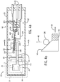
- the latch switch assembly 19 may contain an upper contact 118, a center contact 120, and a lower contact 122 arranged to provide a single pole, double throw electrical switch with the upper contact 118 and lower contact 122 generally flanking the center contact 120.
- the center contact 120 may move between the upper contact 118 and lower contact 120 to selectively and alternatively connect to only one of the upper contact 118 and lower contact 122.
- the center contact 120 may be supported on a relatively rigid conductive lever 124 attached at a knife-edge pivot point 126 to a conductive support bracket 128, the latter communicating with one of the conductive leads 41 and pivot point 126 allowing electrical conduction from the conductive lever 124 to the conductive lead 41.
- the lever 124 By pivoting the lever 124 around the pivot point 126, the lever 124 may be moved upward and downward so that the center contact 120 alternately connects electrically to upper contact 118 and lower contact 122.
- a helical over-center spring 130 attaches to a center portion of the lever 124 and extends away from the center contact 120 to a support post 132 on the housing 46 to provide a force on the lever 124 tending to engage the lever 124 and support bracket 128 at the pivot point 126.
- the paddle 42 when pressed inward (into the page as depicted in Fig. 4a ), causes inward motion of the lever on the side of the fulcrum bar 44 including the paddle 42 and outward motion of the lever 40 on the opposite side of the fulcrum bar 44.
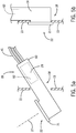
- a cam surface 50 (shown also in Fig. 4b ) attached at the opposed end of the lever 40 pushes outward as indicated by arrow 43 which deflects a center region of the helical over-center spring 130 upward indicated by arrow 45 to change its line of action 142 with respect to the pivot point 126.
- the line of action 142 represents a force vector asserted on the lever 124 by the helical over-center spring 130. When the line of action 142 is above the pivot point 126, the lever 124 will snap rapidly upward, and when the line of action 142 is below the pivot point 126, lever 124 will snap rapidly downward.
- the upper contact 118 and lower contact 122 are each generally supported on cantilevered conductive metal leaf springs 123 which communicate to one of the conductive leads 41.
- the metal leaf springs 123 extend from their respective contacts 118 and 122 in the opposite directions as the lever 124 so that the conductive leads 41 may exit from a top of the housing 29 to reduce the chance of water ingress.
- the housing 29 provides an elongate section 60 holding electrical switch 62 of contacts 118 and 122 displaced away from the insertion axis 27 so that the electrical switch 62 may be mounted above the opening 22 when the frame flange 21 abuts the rear surface of the front wall 13 around the opening 18.
- the elongate section 60 extends along a rear surface of the front wall 13 closely adjacent thereto.
- the cross-sectional dimensions of the elongate section 60 are sized to fit freely through the opening 18 and the opening 18 sized with respect to the frame flange 21 to allow the housing 29 to be rocked into a vertical position during installation after the elongate section 60 passes through the opening 18.
Landscapes
- Engineering & Computer Science (AREA)
- Textile Engineering (AREA)
- Computer Security & Cryptography (AREA)
- Push-Button Switches (AREA)
- Clamps And Clips (AREA)
- Tumbler Switches (AREA)
Claims (13)
- Verriegelungsschalteranordnung (19), die vorgesehen ist, um eine Verriegelungsklinke (24) anzunehmen und festzuhalten, wobei die Verriegelungsschalteranordnung ein Gehäuse (29) umfasst, welches hält:ein Paar Backenelemente (25), die getrennt zueinander hin und voneinander weg über eine Einschubachse (27) beweglich sind;ein Federelement (32), welches die Backenelemente (25) zueinander hin vorspannt, so dass sie sich trennen können, um die Verriegelungsklinke (24) entlang der Einschubachse (27) zu empfangen und die Verriegelungsklinke (24) nach Empfang unter der Kraft des Federelements (32) zu halten; undeinen Elektroschalter (62) mit einem Bediener, der hinter den Backenelementen (25) in Bezug auf eine Empfangsrichtung der Verriegelungsklinke (24) entlang der Einschubachse (27) positioniert ist, um durch die Verriegelungsklinke (24) bedient zu werden, wenn diese empfangen wird,dadurch gekennzeichnet, dassdie Backenelemente (25) ein Polymermaterial in Form von gerundeten Stäben sind, und dass das Federelement (32) eine U-förmige Metallklemme mit gegenüber liegenden und getrennten Armen ist, die an oberen beziehungsweise unteren gegenüber liegenden Backenelementen (25) befestigt sind und sich rückwärts entlang der Einschubachse (27) erstrecken.
- Verriegelungsschalteranordnung nach Anspruch 1, wobei das Federelement (32) Metallzähne bereitstellt, die in die Backenelemente (25) passen, um in Abwesenheit der Backenelemente (25) eine Verriegelungsklinke (24) zu greifen, die dazwischen positioniert ist.
- Verriegelungsschalteranordnung nach Anspruch 1 oder 2, wobei die U-förmige Metallklemme an dem Gehäuse (29), welches das Federelement (32) und den Elektroschalter (62) trägt, an einem Mittelabschnitt der U-förmigen Metallklemme im Wesentlichen auf halbem Wege zwischen den Armen befestigt ist.
- Verriegelungsschalteranordnung nach einem der vorhergehenden Ansprüche, wobei der Schalterbediener ein Hebelarm (40) ist, der sich von einer Position hinter den Backenelementen (25) in Bezug auf die Einschubachse (27) zu elektrischen Kontakten (118, 120, 122) des Elektroschalters (62) erstreckt, die von der Einschubachse (27) senkrecht von der Position hinter den Backenelementen (25) verschoben sind.
- Verriegelungsschalteranordnung nach Anspruch 4, wobei mindestens ein elektrischer Kontakt (118, 120, 122) auf Metallblattfedern (123) getragen wird, die sich senkrecht zu der Einschubachse (27) erstrecken.
- Verriegelungsschalteranordnung nach einem der vorhergehenden Ansprüche, wobei die U-förmige Metallklemme mindestens einen Schlitz (38) in einem Arm einschließt, der Durchgang des Hebelarms (40) zulässt.
- Verriegelungsschalteranordnung nach einem der Ansprüche 4 bis 6, wobei ein Ende des Hebelarms (40) hinter den gegenüber liegenden Backenelementen (25) eine Platte (42) bereitstellt, die sich von einer der Seiten des Hebelarms (40) entlang einer Kontaktlinie zwischen den gegenüber liegenden Backenelementen (25) erstreckt, wenn die Backenelemente (25) zusammengepresst werden.
- Verriegelungsschalteranordnung nach einem der Ansprüche 4 bis 7, wobei der Hebelarm (40) einen Schwenkzapfen (44) einschließt, der an einem Gehäuse (29), welches das Federelement (32) und den Elektroschalter (62) trägt, angebracht ist, um in Bezug zu dem Gehäuse (29) zu schwenken.
- Verriegelungsschalteranordnung nach einem der Ansprüche 4 bis 8, wobei das Ende des Hebelarms (40), das sich von der Position hinter den Backenelementen (25) weg erstreckt, eine Schnappfeder (130) kontaktiert, die ein schnappendes Öffnen und Schließen der elektrischen Kontakte (118, 120, 122) bereitstellt.
- Verriegelungsschalteranordnung nach einem der vorhergehenden Ansprüche, wobei das Gehäuse (29) eine Öffnung (22) bereitstellt, die die Backenelemente (25) entlang der Einschubachse (27) exponiert.
- Verriegelungsschalteranordnung nach Anspruch 10, wobei die Öffnung (22) einen Flansch (21) einschließt, der sich entlang einer Ebene um die Öffnung herum und senkrecht zu der Einschubachse (27) erstreckt.
- Verriegelungsschalteranordnung nach einem der vorhergehenden Ansprüche, wobei das Gehäuse (29) sich aufwärts entlang einer Rückseite der Ebene der Öffnung (22) hinter dem Flansch (21) erstreckt und so bemessen ist, dass es schraubend durch eine Öffnung in einem Haushaltsgerät gelangt, die so bemessen ist, dass sie durch den Flansch (21) bedeckt wird, wenn der Flansch gegen die Öffnung platziert wird.
- Verriegelungsschalteranordnung nach einem der vorhergehenden Ansprüche, ferner einschließend eine Verriegelungsklinke (24) mit einem knolligen entfernten Ende (28), das sich an seiner Front verjüngt, um das Paar der Backenelemente (25) zu trennen, wenn die Verriegelungsklinke (24) entlang der Einschubachse (27) bewegt wird, so dass das Paar der Backenelemente (25) sich trennt, um über das knollige entfernte Ende (28) zu gelangen, wobei die Verriegelungsklinke (24) entlang der Einschubachse (27) eingeschoben wird, und sich hinter dem knolligen Ende mit einer Federkraft zusammen zu bewegen, um die Verriegelungsklinke (24) gegen eine vorbestimmte Rückhaltekraft festzuhalten.
Priority Applications (1)
| Application Number | Priority Date | Filing Date | Title |
|---|---|---|---|
| PL15711600T PL3129539T3 (pl) | 2014-04-09 | 2015-02-27 | Ukryty przełącznik drzwiczek suszarki |
Applications Claiming Priority (2)
| Application Number | Priority Date | Filing Date | Title |
|---|---|---|---|
| US201461977316P | 2014-04-09 | 2014-04-09 | |
| PCT/US2015/018022 WO2015156918A1 (en) | 2014-04-09 | 2015-02-27 | Hidden dryer door switch |
Publications (2)
| Publication Number | Publication Date |
|---|---|
| EP3129539A1 EP3129539A1 (de) | 2017-02-15 |
| EP3129539B1 true EP3129539B1 (de) | 2018-04-18 |
Family
ID=52706278
Family Applications (1)
| Application Number | Title | Priority Date | Filing Date |
|---|---|---|---|
| EP15711600.5A Active EP3129539B1 (de) | 2014-04-09 | 2015-02-27 | Verborgener trocknertürkontaktschalter |
Country Status (7)
| Country | Link |
|---|---|
| US (1) | US10023992B2 (de) |
| EP (1) | EP3129539B1 (de) |
| KR (1) | KR102416105B1 (de) |
| CN (1) | CN106164360B (de) |
| PL (1) | PL3129539T3 (de) |
| TR (1) | TR201808528T4 (de) |
| WO (1) | WO2015156918A1 (de) |
Families Citing this family (5)
| Publication number | Priority date | Publication date | Assignee | Title |
|---|---|---|---|---|
| US10443183B2 (en) * | 2017-03-20 | 2019-10-15 | Haier Us Appliance Solutions, Inc. | Dryer appliance and related methods |
| EP3931388B1 (de) | 2019-02-27 | 2023-10-04 | Electrolux Appliances Aktiebolag | Verfahren zum waschen von wäsche in einer wäschewaschmaschine und wäschewaschmaschine mit implementierung des verfahrens |
| CN115954219A (zh) * | 2021-10-08 | 2023-04-11 | 上海良信电器股份有限公司 | 一种具有导向功能的接插件动触头系统 |
| US11913266B2 (en) * | 2021-10-27 | 2024-02-27 | Whirlpool Corporation | Door assembly for a household appliance |
| US12378715B2 (en) | 2021-12-29 | 2025-08-05 | Electrolux Appliances Aktiebolag | Laundry machine door assembly |
Family Cites Families (11)
| Publication number | Priority date | Publication date | Assignee | Title |
|---|---|---|---|---|
| US3742162A (en) * | 1971-10-27 | 1973-06-26 | Westinghouse Electric Corp | Self-contained door safety switch with manually disabled latch |
| US4230919A (en) * | 1978-03-13 | 1980-10-28 | Schantz Spencer C | Snap acting switch |
| US5025121A (en) * | 1988-12-19 | 1991-06-18 | Siemens Energy & Automation, Inc. | Circuit breaker contact assembly |
| US5147992A (en) * | 1990-06-12 | 1992-09-15 | Adc Telecommunications, Inc. | Jack assembly |
| KR100987443B1 (ko) * | 2003-08-27 | 2010-10-13 | 엘지전자 주식회사 | 드럼세탁기의 로터리 놉 어셈블리 구조 |
| US7038156B2 (en) * | 2003-08-27 | 2006-05-02 | Lg Electronics Inc. | Rotary knob assembly for home appliance |
| US8118332B2 (en) * | 2008-04-17 | 2012-02-21 | Illinois Tool Works Inc. | Latch device |
| US9410349B2 (en) | 2010-04-26 | 2016-08-09 | Illinois Tool Works Inc. | Appliance latch with improved door retention at elevated temperatures |
| US8853582B2 (en) | 2011-07-12 | 2014-10-07 | Illinois Tool Works Inc. | Electrical switch with shear force contact weld release |
| JP5831829B2 (ja) | 2011-07-25 | 2015-12-09 | Kyb株式会社 | 懸架装置 |
| CN202277319U (zh) * | 2011-10-17 | 2012-06-20 | 美的集团有限公司 | 一种家用洗碗机的门锁组件 |
-
2015
- 2015-02-27 PL PL15711600T patent/PL3129539T3/pl unknown
- 2015-02-27 CN CN201580018444.0A patent/CN106164360B/zh active Active
- 2015-02-27 WO PCT/US2015/018022 patent/WO2015156918A1/en not_active Ceased
- 2015-02-27 EP EP15711600.5A patent/EP3129539B1/de active Active
- 2015-02-27 US US15/301,984 patent/US10023992B2/en active Active
- 2015-02-27 TR TR2018/08528T patent/TR201808528T4/tr unknown
- 2015-02-27 KR KR1020167025794A patent/KR102416105B1/ko active Active
Non-Patent Citations (1)
| Title |
|---|
| None * |
Also Published As
| Publication number | Publication date |
|---|---|
| EP3129539A1 (de) | 2017-02-15 |
| TR201808528T4 (tr) | 2018-07-23 |
| KR102416105B1 (ko) | 2022-07-04 |
| US20170175321A1 (en) | 2017-06-22 |
| PL3129539T3 (pl) | 2018-09-28 |
| US10023992B2 (en) | 2018-07-17 |
| KR20160140628A (ko) | 2016-12-07 |
| CN106164360A (zh) | 2016-11-23 |
| CN106164360B (zh) | 2018-10-23 |
| WO2015156918A1 (en) | 2015-10-15 |
Similar Documents
| Publication | Publication Date | Title |
|---|---|---|
| US10023992B2 (en) | Hidden dryer door switch | |
| EP2475815B1 (de) | Gerätesperre mit mechanischem türsensor | |
| CN101479423B (zh) | 用于家用电器的门盖 | |
| US11859337B2 (en) | Tamper resistant appliance latch | |
| CN105839352B (zh) | 器械锁 | |
| KR20090115018A (ko) | 의류처리장치의 도어스위치어셈블리 | |
| CN111315927A (zh) | 抗污染的电器闩锁 | |
| EP3037579B1 (de) | Verriegelungsvorrichtung zum Schließen der Tür eines Haushaltsgeräts | |
| EP2808434B1 (de) | Wäschebehandlungsvorrichtung mit Türanordnung | |
| WO2005014913A1 (en) | A washer/dryer | |
| EP2564000B1 (de) | Geräteverriegelung mit verbesserter türrückhaltung bei hohen temperaturen | |
| US9443670B2 (en) | Contamination resistant push button switch | |
| CN109686627A (zh) | 多功能断路器的多级联动系统 | |
| US9607788B2 (en) | Compact contamination resistant push button switch | |
| KR100809357B1 (ko) | 가전제품의 도어락 장치 | |
| US3849615A (en) | Switch holder and actuating apparatus in a hinged closure appliance | |
| EP1726750B1 (de) | Eine Vorrichtung zum Verriegeln einer Bullaugentür einer Waschmaschine | |
| KR200422722Y1 (ko) | 가전기기용 도어스위치 | |
| US7985934B2 (en) | Clothes dryer | |
| JP2004344294A (ja) | 洗濯機 | |
| KR0128871Y1 (ko) | 세탁기 도어 자동개폐용 스위치 | |
| KR20090115021A (ko) | 의류처리장치의 도어스위치어셈블리 | |
| JP2000051570A (ja) | 洗濯機 | |
| JP2000051574A (ja) | 洗濯機 | |
| JP2000051571A (ja) | 洗濯機 |
Legal Events
| Date | Code | Title | Description |
|---|---|---|---|
| STAA | Information on the status of an ep patent application or granted ep patent |
Free format text: STATUS: THE INTERNATIONAL PUBLICATION HAS BEEN MADE |
|
| PUAI | Public reference made under article 153(3) epc to a published international application that has entered the european phase |
Free format text: ORIGINAL CODE: 0009012 |
|
| STAA | Information on the status of an ep patent application or granted ep patent |
Free format text: STATUS: REQUEST FOR EXAMINATION WAS MADE |
|
| 17P | Request for examination filed |
Effective date: 20160914 |
|
| AK | Designated contracting states |
Kind code of ref document: A1 Designated state(s): AL AT BE BG CH CY CZ DE DK EE ES FI FR GB GR HR HU IE IS IT LI LT LU LV MC MK MT NL NO PL PT RO RS SE SI SK SM TR |
|
| AX | Request for extension of the european patent |
Extension state: BA ME |
|
| DAX | Request for extension of the european patent (deleted) | ||
| STAA | Information on the status of an ep patent application or granted ep patent |
Free format text: STATUS: EXAMINATION IS IN PROGRESS |
|
| 17Q | First examination report despatched |
Effective date: 20170803 |
|
| GRAP | Despatch of communication of intention to grant a patent |
Free format text: ORIGINAL CODE: EPIDOSNIGR1 |
|
| STAA | Information on the status of an ep patent application or granted ep patent |
Free format text: STATUS: GRANT OF PATENT IS INTENDED |
|
| RIC1 | Information provided on ipc code assigned before grant |
Ipc: A47L 15/42 20060101ALI20171120BHEP Ipc: D06F 37/42 20060101AFI20171120BHEP Ipc: H01H 3/16 20060101ALI20171120BHEP Ipc: D06F 58/28 20060101ALI20171120BHEP Ipc: H01H 9/22 20060101ALI20171120BHEP |
|
| INTG | Intention to grant announced |
Effective date: 20171222 |
|
| GRAS | Grant fee paid |
Free format text: ORIGINAL CODE: EPIDOSNIGR3 |
|
| GRAA | (expected) grant |
Free format text: ORIGINAL CODE: 0009210 |
|
| STAA | Information on the status of an ep patent application or granted ep patent |
Free format text: STATUS: THE PATENT HAS BEEN GRANTED |
|
| AK | Designated contracting states |
Kind code of ref document: B1 Designated state(s): AL AT BE BG CH CY CZ DE DK EE ES FI FR GB GR HR HU IE IS IT LI LT LU LV MC MK MT NL NO PL PT RO RS SE SI SK SM TR |
|
| REG | Reference to a national code |
Ref country code: GB Ref legal event code: FG4D |
|
| REG | Reference to a national code |
Ref country code: CH Ref legal event code: EP |
|
| REG | Reference to a national code |
Ref country code: DE Ref legal event code: R096 Ref document number: 602015010133 Country of ref document: DE |
|
| REG | Reference to a national code |
Ref country code: AT Ref legal event code: REF Ref document number: 990596 Country of ref document: AT Kind code of ref document: T Effective date: 20180515 |
|
| REG | Reference to a national code |
Ref country code: IE Ref legal event code: FG4D |
|
| REG | Reference to a national code |
Ref country code: NL Ref legal event code: MP Effective date: 20180418 |
|
| REG | Reference to a national code |
Ref country code: LT Ref legal event code: MG4D |
|
| PG25 | Lapsed in a contracting state [announced via postgrant information from national office to epo] |
Ref country code: NL Free format text: LAPSE BECAUSE OF FAILURE TO SUBMIT A TRANSLATION OF THE DESCRIPTION OR TO PAY THE FEE WITHIN THE PRESCRIBED TIME-LIMIT Effective date: 20180418 |
|
| PG25 | Lapsed in a contracting state [announced via postgrant information from national office to epo] |
Ref country code: NO Free format text: LAPSE BECAUSE OF FAILURE TO SUBMIT A TRANSLATION OF THE DESCRIPTION OR TO PAY THE FEE WITHIN THE PRESCRIBED TIME-LIMIT Effective date: 20180718 Ref country code: FI Free format text: LAPSE BECAUSE OF FAILURE TO SUBMIT A TRANSLATION OF THE DESCRIPTION OR TO PAY THE FEE WITHIN THE PRESCRIBED TIME-LIMIT Effective date: 20180418 Ref country code: LT Free format text: LAPSE BECAUSE OF FAILURE TO SUBMIT A TRANSLATION OF THE DESCRIPTION OR TO PAY THE FEE WITHIN THE PRESCRIBED TIME-LIMIT Effective date: 20180418 Ref country code: BG Free format text: LAPSE BECAUSE OF FAILURE TO SUBMIT A TRANSLATION OF THE DESCRIPTION OR TO PAY THE FEE WITHIN THE PRESCRIBED TIME-LIMIT Effective date: 20180718 Ref country code: ES Free format text: LAPSE BECAUSE OF FAILURE TO SUBMIT A TRANSLATION OF THE DESCRIPTION OR TO PAY THE FEE WITHIN THE PRESCRIBED TIME-LIMIT Effective date: 20180418 Ref country code: SE Free format text: LAPSE BECAUSE OF FAILURE TO SUBMIT A TRANSLATION OF THE DESCRIPTION OR TO PAY THE FEE WITHIN THE PRESCRIBED TIME-LIMIT Effective date: 20180418 Ref country code: AL Free format text: LAPSE BECAUSE OF FAILURE TO SUBMIT A TRANSLATION OF THE DESCRIPTION OR TO PAY THE FEE WITHIN THE PRESCRIBED TIME-LIMIT Effective date: 20180418 |
|
| PG25 | Lapsed in a contracting state [announced via postgrant information from national office to epo] |
Ref country code: RS Free format text: LAPSE BECAUSE OF FAILURE TO SUBMIT A TRANSLATION OF THE DESCRIPTION OR TO PAY THE FEE WITHIN THE PRESCRIBED TIME-LIMIT Effective date: 20180418 Ref country code: LV Free format text: LAPSE BECAUSE OF FAILURE TO SUBMIT A TRANSLATION OF THE DESCRIPTION OR TO PAY THE FEE WITHIN THE PRESCRIBED TIME-LIMIT Effective date: 20180418 Ref country code: GR Free format text: LAPSE BECAUSE OF FAILURE TO SUBMIT A TRANSLATION OF THE DESCRIPTION OR TO PAY THE FEE WITHIN THE PRESCRIBED TIME-LIMIT Effective date: 20180719 Ref country code: HR Free format text: LAPSE BECAUSE OF FAILURE TO SUBMIT A TRANSLATION OF THE DESCRIPTION OR TO PAY THE FEE WITHIN THE PRESCRIBED TIME-LIMIT Effective date: 20180418 |
|
| REG | Reference to a national code |
Ref country code: AT Ref legal event code: MK05 Ref document number: 990596 Country of ref document: AT Kind code of ref document: T Effective date: 20180418 |
|
| PG25 | Lapsed in a contracting state [announced via postgrant information from national office to epo] |
Ref country code: PT Free format text: LAPSE BECAUSE OF FAILURE TO SUBMIT A TRANSLATION OF THE DESCRIPTION OR TO PAY THE FEE WITHIN THE PRESCRIBED TIME-LIMIT Effective date: 20180820 |
|
| REG | Reference to a national code |
Ref country code: DE Ref legal event code: R097 Ref document number: 602015010133 Country of ref document: DE |
|
| PG25 | Lapsed in a contracting state [announced via postgrant information from national office to epo] |
Ref country code: DK Free format text: LAPSE BECAUSE OF FAILURE TO SUBMIT A TRANSLATION OF THE DESCRIPTION OR TO PAY THE FEE WITHIN THE PRESCRIBED TIME-LIMIT Effective date: 20180418 Ref country code: CZ Free format text: LAPSE BECAUSE OF FAILURE TO SUBMIT A TRANSLATION OF THE DESCRIPTION OR TO PAY THE FEE WITHIN THE PRESCRIBED TIME-LIMIT Effective date: 20180418 Ref country code: RO Free format text: LAPSE BECAUSE OF FAILURE TO SUBMIT A TRANSLATION OF THE DESCRIPTION OR TO PAY THE FEE WITHIN THE PRESCRIBED TIME-LIMIT Effective date: 20180418 Ref country code: SK Free format text: LAPSE BECAUSE OF FAILURE TO SUBMIT A TRANSLATION OF THE DESCRIPTION OR TO PAY THE FEE WITHIN THE PRESCRIBED TIME-LIMIT Effective date: 20180418 Ref country code: EE Free format text: LAPSE BECAUSE OF FAILURE TO SUBMIT A TRANSLATION OF THE DESCRIPTION OR TO PAY THE FEE WITHIN THE PRESCRIBED TIME-LIMIT Effective date: 20180418 Ref country code: AT Free format text: LAPSE BECAUSE OF FAILURE TO SUBMIT A TRANSLATION OF THE DESCRIPTION OR TO PAY THE FEE WITHIN THE PRESCRIBED TIME-LIMIT Effective date: 20180418 |
|
| PLBE | No opposition filed within time limit |
Free format text: ORIGINAL CODE: 0009261 |
|
| STAA | Information on the status of an ep patent application or granted ep patent |
Free format text: STATUS: NO OPPOSITION FILED WITHIN TIME LIMIT |
|
| PG25 | Lapsed in a contracting state [announced via postgrant information from national office to epo] |
Ref country code: IT Free format text: LAPSE BECAUSE OF FAILURE TO SUBMIT A TRANSLATION OF THE DESCRIPTION OR TO PAY THE FEE WITHIN THE PRESCRIBED TIME-LIMIT Effective date: 20180418 Ref country code: SM Free format text: LAPSE BECAUSE OF FAILURE TO SUBMIT A TRANSLATION OF THE DESCRIPTION OR TO PAY THE FEE WITHIN THE PRESCRIBED TIME-LIMIT Effective date: 20180418 |
|
| 26N | No opposition filed |
Effective date: 20190121 |
|
| PG25 | Lapsed in a contracting state [announced via postgrant information from national office to epo] |
Ref country code: SI Free format text: LAPSE BECAUSE OF FAILURE TO SUBMIT A TRANSLATION OF THE DESCRIPTION OR TO PAY THE FEE WITHIN THE PRESCRIBED TIME-LIMIT Effective date: 20180418 |
|
| REG | Reference to a national code |
Ref country code: CH Ref legal event code: PL |
|
| PG25 | Lapsed in a contracting state [announced via postgrant information from national office to epo] |
Ref country code: MC Free format text: LAPSE BECAUSE OF FAILURE TO SUBMIT A TRANSLATION OF THE DESCRIPTION OR TO PAY THE FEE WITHIN THE PRESCRIBED TIME-LIMIT Effective date: 20180418 Ref country code: LU Free format text: LAPSE BECAUSE OF NON-PAYMENT OF DUE FEES Effective date: 20190227 |
|
| REG | Reference to a national code |
Ref country code: BE Ref legal event code: MM Effective date: 20190228 |
|
| REG | Reference to a national code |
Ref country code: IE Ref legal event code: MM4A |
|
| PG25 | Lapsed in a contracting state [announced via postgrant information from national office to epo] |
Ref country code: LI Free format text: LAPSE BECAUSE OF NON-PAYMENT OF DUE FEES Effective date: 20190228 Ref country code: CH Free format text: LAPSE BECAUSE OF NON-PAYMENT OF DUE FEES Effective date: 20190228 |
|
| PG25 | Lapsed in a contracting state [announced via postgrant information from national office to epo] |
Ref country code: IE Free format text: LAPSE BECAUSE OF NON-PAYMENT OF DUE FEES Effective date: 20190227 |
|
| PG25 | Lapsed in a contracting state [announced via postgrant information from national office to epo] |
Ref country code: FR Free format text: LAPSE BECAUSE OF NON-PAYMENT OF DUE FEES Effective date: 20190228 Ref country code: BE Free format text: LAPSE BECAUSE OF NON-PAYMENT OF DUE FEES Effective date: 20190228 |
|
| PG25 | Lapsed in a contracting state [announced via postgrant information from national office to epo] |
Ref country code: MT Free format text: LAPSE BECAUSE OF NON-PAYMENT OF DUE FEES Effective date: 20190227 |
|
| PG25 | Lapsed in a contracting state [announced via postgrant information from national office to epo] |
Ref country code: CY Free format text: LAPSE BECAUSE OF FAILURE TO SUBMIT A TRANSLATION OF THE DESCRIPTION OR TO PAY THE FEE WITHIN THE PRESCRIBED TIME-LIMIT Effective date: 20180418 |
|
| PG25 | Lapsed in a contracting state [announced via postgrant information from national office to epo] |
Ref country code: IS Free format text: LAPSE BECAUSE OF FAILURE TO SUBMIT A TRANSLATION OF THE DESCRIPTION OR TO PAY THE FEE WITHIN THE PRESCRIBED TIME-LIMIT Effective date: 20180818 |
|
| PG25 | Lapsed in a contracting state [announced via postgrant information from national office to epo] |
Ref country code: HU Free format text: LAPSE BECAUSE OF FAILURE TO SUBMIT A TRANSLATION OF THE DESCRIPTION OR TO PAY THE FEE WITHIN THE PRESCRIBED TIME-LIMIT; INVALID AB INITIO Effective date: 20150227 |
|
| PG25 | Lapsed in a contracting state [announced via postgrant information from national office to epo] |
Ref country code: MK Free format text: LAPSE BECAUSE OF FAILURE TO SUBMIT A TRANSLATION OF THE DESCRIPTION OR TO PAY THE FEE WITHIN THE PRESCRIBED TIME-LIMIT Effective date: 20180418 |
|
| P01 | Opt-out of the competence of the unified patent court (upc) registered |
Effective date: 20230606 |
|
| PGFP | Annual fee paid to national office [announced via postgrant information from national office to epo] |
Ref country code: GB Payment date: 20260227 Year of fee payment: 12 |
|
| PGFP | Annual fee paid to national office [announced via postgrant information from national office to epo] |
Ref country code: DE Payment date: 20260227 Year of fee payment: 12 |
|
| PGFP | Annual fee paid to national office [announced via postgrant information from national office to epo] |
Ref country code: TR Payment date: 20260206 Year of fee payment: 12 |
|
| PGFP | Annual fee paid to national office [announced via postgrant information from national office to epo] |
Ref country code: PL Payment date: 20260206 Year of fee payment: 12 |