EP3129678B1 - Spindelmutter mit asymmetrischem innengewinde sowie entsprechender gleitgewindetrieb - Google Patents
Spindelmutter mit asymmetrischem innengewinde sowie entsprechender gleitgewindetrieb Download PDFInfo
- Publication number
- EP3129678B1 EP3129678B1 EP14715338.1A EP14715338A EP3129678B1 EP 3129678 B1 EP3129678 B1 EP 3129678B1 EP 14715338 A EP14715338 A EP 14715338A EP 3129678 B1 EP3129678 B1 EP 3129678B1
- Authority
- EP
- European Patent Office
- Prior art keywords
- thread
- spindle nut
- spindle
- set forth
- nut
- Prior art date
- Legal status (The legal status is an assumption and is not a legal conclusion. Google has not performed a legal analysis and makes no representation as to the accuracy of the status listed.)
- Active
Links
Images
Classifications
-
- F—MECHANICAL ENGINEERING; LIGHTING; HEATING; WEAPONS; BLASTING
- F16—ENGINEERING ELEMENTS AND UNITS; GENERAL MEASURES FOR PRODUCING AND MAINTAINING EFFECTIVE FUNCTIONING OF MACHINES OR INSTALLATIONS; THERMAL INSULATION IN GENERAL
- F16H—GEARING
- F16H25/00—Gearings comprising primarily only cams, cam-followers and screw-and-nut mechanisms
- F16H25/18—Gearings comprising primarily only cams, cam-followers and screw-and-nut mechanisms for conveying or interconverting oscillating or reciprocating motions
- F16H25/20—Screw mechanisms
- F16H25/24—Elements essential to such mechanisms, e.g. screws, nuts
-
- F—MECHANICAL ENGINEERING; LIGHTING; HEATING; WEAPONS; BLASTING
- F16—ENGINEERING ELEMENTS AND UNITS; GENERAL MEASURES FOR PRODUCING AND MAINTAINING EFFECTIVE FUNCTIONING OF MACHINES OR INSTALLATIONS; THERMAL INSULATION IN GENERAL
- F16H—GEARING
- F16H55/00—Elements with teeth or friction surfaces for conveying motion; Worms, pulleys or sheaves for gearing mechanisms
- F16H55/02—Toothed members; Worms
- F16H55/08—Profiling
-
- F—MECHANICAL ENGINEERING; LIGHTING; HEATING; WEAPONS; BLASTING
- F16—ENGINEERING ELEMENTS AND UNITS; GENERAL MEASURES FOR PRODUCING AND MAINTAINING EFFECTIVE FUNCTIONING OF MACHINES OR INSTALLATIONS; THERMAL INSULATION IN GENERAL
- F16H—GEARING
- F16H25/00—Gearings comprising primarily only cams, cam-followers and screw-and-nut mechanisms
- F16H25/18—Gearings comprising primarily only cams, cam-followers and screw-and-nut mechanisms for conveying or interconverting oscillating or reciprocating motions
- F16H25/20—Screw mechanisms
- F16H25/24—Elements essential to such mechanisms, e.g. screws, nuts
- F16H2025/2481—Special features for facilitating the manufacturing of spindles, nuts, or sleeves of screw devices
-
- F—MECHANICAL ENGINEERING; LIGHTING; HEATING; WEAPONS; BLASTING
- F16—ENGINEERING ELEMENTS AND UNITS; GENERAL MEASURES FOR PRODUCING AND MAINTAINING EFFECTIVE FUNCTIONING OF MACHINES OR INSTALLATIONS; THERMAL INSULATION IN GENERAL
- F16H—GEARING
- F16H25/00—Gearings comprising primarily only cams, cam-followers and screw-and-nut mechanisms
- F16H25/18—Gearings comprising primarily only cams, cam-followers and screw-and-nut mechanisms for conveying or interconverting oscillating or reciprocating motions
- F16H25/20—Screw mechanisms
- F16H25/24—Elements essential to such mechanisms, e.g. screws, nuts
- F16H2025/249—Materials or coatings for screws or nuts
Definitions
- the invention generally relates to a spindle nut for a sliding screw drive or sliding screw drive.
- the invention further relates to a sliding screw drive for converting a rotary movement into a longitudinal movement or vice versa, with a spindle and a spindle nut, at least the internal thread of the spindle nut or preferably the entire spindle nut being made of plastic and the external thread of the spindle having a higher strength than the internal thread made of plastic.
- the present invention relates to sliding screw drives. It is known to use a spindle nut made of plastic in such sliding screw drives on a spindle with high strength, for example made of steel. Such a sliding screw drive is, for example, from the published patent application DE 2300851 previously known.
- Sliding screw drives with spindle nuts made of plastic offer the particular advantage that they can be operated with very little maintenance, especially without lubricant.
- the EP 2 581 209 A1 describes such a sliding screw drive, especially for operating a press piston, in which the internal and external threads are asymmetrical to one another, ie with different geometries.
- the flanks of the internal thread of the spindle nut are not mirror-symmetrical but asymmetrically formed with respect to a radial plane.
- a return flank has a significantly flatter angle compared to the working flank, which means that the spindle nut can absorb higher forces in a drive direction, since the thread at the tooth base of the spindle nut is better supported.
- the EP 2 581 209 A1 considered the closest state of the art.
- the state of the art also includes a screw drive according to the preamble in claim 1, such as the EP 2 003 370 A2 disclosed.
- the task is already solved in that the internal thread of the spindle nut has a thread cross section such that the profile sectional area of the threaded helix intended for engagement in the thread of the spindle is measurably larger than the free threaded sectional area of the thread of the spindle nut.
- the cut surfaces are cross-sectional surfaces viewed in a longitudinal section through the central longitudinal axis of the Spindle nut or the spindle, which corresponds to the schematic profile cut.
- the profile cutting surface refers to the cutting surface of the thread helix or teeth of the spindle nut viewed in this plane, measured between a parallel to the longitudinal axis at the thread base and the apex or apex.
- the thread cutting surface refers to the correspondingly considered free surface of the thread of the spindle nut thread, into which the thread helix or teeth of the external thread of the spindle engages.
- the profile sectional area of the internal thread of the spindle nut is larger by a factor of at least 1.2 than the free threaded sectional area of the internal thread.
- the thread cutting surface refers to the free surface of the thread.
- thread is understood to mean the recess in the thread or the thread groove and not the thread helix or toothing.
- the positive profile cutting surface has an area dimension that is in the range of 1.2 times to 2 times, particularly preferably in the range of 1.25 times to 1.4 times, the corresponding area dimension of the gear cutting surface having.
- flank angle that is quite large for movement threads is provided in the range of 30° to 70°, in particular in the range of 45° to 70°.
- flank angle is understood to mean the angle from one thread flank to the opposite thread flank. Higher efficiency can be achieved through appropriately optimized flank angles, while at the same time high loads can be achieved in both translation directions, i.e. regardless of the direction of rotation.
- flank to thread crest and from flank to thread root are rounded. This applies in particular to the internal thread of the spindle nut, but advantageously also to the external thread of the spindle.
- the spindle nut With correspondingly rounded transitions on the spindle nut, it is advantageous if it has a thread cross section whose thread crests are continuously rounded between the two flanks of a thread helix, which is provided according to the invention. In this way, instead of the usual surface contact, point contact of the thread crests can be achieved, which also reduces vibration and noise.
- a continuous rounding can also be provided on the external thread of the spindle, although here the radius of curvature is also reduced by a corresponding factor mentioned at the beginning due to the significantly narrower thread base is appropriate.
- the spindle nut has an internal thread with a thread depth that is less than the thread depth of the external thread on the spindle. In this way, it can be achieved that even in the event of unwanted skewing, only minimal contact (point contact in the longitudinal section) occurs between the thread crests of the external thread and the bottom of the thread groove (groove base) of the spindle nut. In any case, there is no contact between the thread crests of the internal thread and the groove base on the core of the external thread, even in the event of undesirable transverse loads or deformations.
- the spindle nut is expediently made from an engineering plastic.
- the spindle nut is particularly preferably made from a technical plastic, injection-mouldable, preferably lubricating-free high-performance polymer, in particular with fillers and/or reinforcing materials to improve the fatigue strength and reduce the coefficient of friction.
- the spindle nut is manufactured as a one-piece part and consists of plastic. For example, this can preferably be done completely in one operation using the injection molding process, i.e. the spindle nut is cast completely with the nut thread, or by machining a blank that is cast or extruded. If necessary, in both cases the area of the internal thread can be machined or reworked, e.g. by turning or unscrewing. Production in two half-shells that are subsequently joined together is also conceivable and can be more easily achieved using injection molding technology.
- a one-piece spindle nut achieves a high level of precision without any special measures.
- the embodiments according to the invention are multi-threaded to increase the load capacity to increase.
- spindle nuts with a three-start, four-start, five-start, etc. up to a high number of threads, for example a twenty-start internal thread, with relatively little effort.
- the spindle in and of itself can be a purely metallic spindle, for example made of stainless Cr-Mi steel or aluminum. Also within the scope of the invention, however, is a pure plastic spindle, in particular a spindle made of a plastic with higher strength than the plastic of the internal thread of the spindle nut or the spindle nut as a whole. Furthermore, it is within the scope of the invention to provide a plastic or metal spindle with a suitable coating, for example to improve wear resistance and/or optimize friction values. Regardless of the sliding screw drive, the invention also relates to a spindle nut in and of itself with the above-mentioned features. This can be designed, for example, as a flange threaded nut.
- the invention also relates to the use of a such a spindle nut in a sliding screw drive.
- Typical areas of application of the invention are areas in which the absence of lubricants is particularly advantageous or desirable, for example in clean room or medical technology.
- the sliding screw drive according to the invention and the corresponding spindle nut are suitable for a variety of other areas of application, for example in automobile construction, in automation systems, etc.
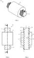
- FIG.1-4 show a sliding screw drive 10 for converting a rotation of a spindle 11 into a longitudinal movement of a spindle nut 12.
- the spindle nut 12 is made in one piece from plastic by injection molding.
- the spindle nut 12 consists of a high-performance polymer, in particular with fillers and/or reinforcing materials to achieve lubricant-free and low-friction operation.
- the spindle 11 is made of stainless Cr-Ni steel, which has a higher strength compared to technical plastic of the spindle nut 12.
- the external thread 30 of the spindle 11 is, for example, five-start, that is, has five thread spirals 31.
- the internal thread 20 of the spindle nut 12 also has five thread spirals 31 of the spindle rounded at their apexes with approximately the radius R2.
- the internal thread 20 and the external thread 30 are designed asymmetrically relative to one another, because the thread spirals 21 of the spindle nut 12 are significantly larger than the thread spirals 31 of the spindle 11.
- the thread groove or the thread turn 22 of the internal thread behave accordingly in a conjugate or complementary manner 20 and the thread 22 of the external thread 30, because the thread spirals 21 of the spindle nut 12 are in engagement with the threads 32 of the spindle 11 and vice versa.
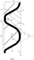
- FIG.4 an enlargement of the thread cross section of the internal thread 20 of the spindle nut 12, the internal thread 20 has a thread cross section in which profile sectional area S1 (roughly hatched) of the thread helix 21 is larger by a factor of approximately 1.28-1.32 here than the free thread cutting surface S2 (finely hatched) of the thread 22, ie the thread groove of the spindle nut 12.
- the quotient S1/S2 in this example fulfills the inequality: 1.28 ⁇ S1/S2 ⁇ 1.32 (whereby depending on the size at the A measurement or manufacturing tolerance of in the range of approximately 1-5% can be assumed).
- the profile sectional area S1 and the gear sectional area S2 are the ones in the profile section FIG.4 measured areas between the dashed parallels to the longitudinal axis, with one parallel (left in FIG.4 ) runs through the threaded base 26 or forms a tangent to the groove bases 25 and the other parallel forms a tangent to the vertices 24.
- the thread crest 24 is preferably rounded continuously between the flanks 23 (circular in profile section), preferably with a rounding radius R1, for example approximately R1 ⁇ 1.6mm for a 5-start thread with a 25mm pitch (and 6.35mm nominal diameter), ie R1 corresponds 0.32 times the value of 1/5 of the thread pitch (corresponding to 5mm axial length of thread helix plus thread turn).
- the transition from each flank 23 to the groove base 25 is also rounded with a rounding radius R2, where R2 ⁇ R1. Accordingly, the profile section of the spindle 11 is preferably provided with curves at both transitions. A design with a profile similar to a round thread, ie completely without edges, is therefore particularly preferred.
- the thread depth T1 of the external thread 30 of the spindle 11 is slightly larger than the thread depth T2 of the internal thread 20 of the spindle nut 12. This creates a helical line contact at most between the vertices External thread 30 and the respective groove base 25 of the internal thread 20.
- flanks 23, 33 are each mirror-symmetrical with respect to an imaginary radial plane through the profile section in the internal thread 20 and external thread 30 FIG.3-4 executed. They include a flank angle ⁇ that is unusually large for moving threads, as shown in the example FIG.1-4 of about 50-60°. Due to the plastic properties and the good resilience of the thread spirals 21 of the internal thread 20, such large flank angles ⁇ can be achieved.
- spindle nut 12 unlike in FIG.1-3 shown, in particular can be designed as a flange threaded nut.
Landscapes
- Engineering & Computer Science (AREA)
- General Engineering & Computer Science (AREA)
- Mechanical Engineering (AREA)
- Transmission Devices (AREA)
Description
- Die Erfindung betrifft allgemein eine Spindelmutter für einen Gleitgewindetrieb bzw. Gleitgewindeantrieb. Die Erfindung betrifft ferner einen Gleitgewindetrieb zur Umsetzung einer Drehbewegung in eine Längsbewegung oder umgekehrt, mit einer Spindel und einer Spindelmutter, wobei zumindest das Innengewinde der Spindelmutter oder vorzugsweise die gesamte Spindelmutter aus Kunststoff gefertigt ist und das Außengewinde der Spindel eine höhere Festigkeit aufweist als das Innengewinde aus Kunststoff.
- Bei Gewindetrieben wird zwischen Wälzgewindetrieben, wie beispielsweise Kugelgewindetrieben mit Kugeln als Wälzkörpern, und sogenannten konventionellen Gleitgewindetrieben unterschieden. Die vorliegende Erfindung betrifft Gleitgewindetriebe. Es ist bekannt, bei solchen Gleitgewindetrieben auf einer Spindel mit hoher Festigkeit, beispielsweise aus Stahl, eine Spindelmutter aus Kunststoff zu verwenden. Ein derartiger Gleitgewindetrieb ist beispielsweise aus der Offenlegungsschrift
DE 2300851 vorbekannt. - Gleitgewindetriebe mit Spindelmuttern aus Kunststoff bieten insbesondere den Vorteil, dass sie sehr wartungsarm, insbesondere schmiermittelfrei, betrieben werden können.
- Die
EP 2 581 209 A1 beschreibt einen solchen Gleitgewindetrieb, speziell zum Betreiben eines Presskolbens, bei welchem Innen- und Außengewinde zueinander asymmetrisch, d.h. mit verschiedenen Geometrien ausgeführt sind. Beim Spindeltrieb gemäßEP 2 581 209 A1 sind die Flanken des Innengewindes der Spindelmutter bezüglich einer Radialebene nicht spiegelsymmetrisch, sondern asymmetrisch ausgebildet. Hierbei weist eine Rückholflanke gegenüber der Arbeitsflanke einen deutlich flacheren Winkel auf, wodurch die Spindelmutter höhere Kräfte in einer Antriebsrichtung aufnehmen kann, da das Gewinde am Zahnfuß der Spindelmutter eine bessere Abstützung erfährt. Durch diese Gestaltung soll auch bei hohen Belastungen, wo bisher üblicherweise Stahl als Material für die Spindelmutter notwendig war, Kunststoff als Material für die Spindelmutter eingesetzt werden können. In Anbetracht dieser Zielsetzung wird dieEP 2 581 209 A1 als nächstliegender Stand der Technik betrachtet. Zum Stand der Technik gehört auch ein Gewindetrieb nach dem Oberbegriff in Anspruch 1, wie beispielsweise dieEP 2 003 370 A2 offenbart. - Ausgehend vom vorgenannten Stand der Technik ist es eine Aufgabe der vorliegenden Erfindung, eine Spindelmutter, welche vollständig oder zumindest im Bereich ihres Innengewindes aus Kunststoff gefertigt ist, vorzuschlagen, welche eine höhere Lebensdauer bietet und für eine größere Vielzahl von Anwendungen geeignet ist. Es soll ebenfalls ein Gleitgewindetrieb mit einer solchen Spindelmutter vorgeschlagen werden.
- Die vorgenannte Aufgabe wird durch eine Spindelmutter für einen Gleitgewindetrieb nach Anspruch gelöst.
- In der einfachsten Ausführungsform wird die Aufgabe bereits dadurch gelöst, dass das Innengewinde der Spindelmutter einen Gewindequerschnitt dergestalt aufweist, dass die zum Eingriff in den Gewindegang der Spindel bestimmte Profilschnittfläche der Gewindewendel messbar größer ist als die freie Gangschnittfläche des Gewindegangs der Spindelmutter. Die Schnittflächen sind hierbei Querschnittsflächen betrachtet in einem Längsschnitt durch die zentrale Längsachse der Spindelmutter bzw. der Spindel, was dem schematisierten Profilschnitt entspricht. Die Profilschnittfläche bezeichnet die in dieser Ebene betrachtete Schnittfläche der Gewindewendel bzw. Verzahnung der Spindelmutter, gemessen zwischen einer Parallelen zur Längsachse am Gewindefuß und dem Scheitel bzw. Scheitelpunkt. Die Gangschnittfläche bezeichnet die entsprechend betrachtete freie Fläche des Gewindegangs des Spindelmutter-Gewindes, in welche die Gewindewendel bzw. Verzahnung des Außengewindes der Spindel eingreift.
- In bevorzugter Ausführung ist die Profilschnittfläche des Innengewindes der Spindelmutter um einen Faktor von mindestens 1,2 größer als die freie Gangschnittfläche des Innengewindes. Die Gangschnittfläche bezeichnet die freie Fläche des Gewindegangs. Vorliegend ist unter Gewindegang die Aussparung des Gewindes bzw. die Gewinderille zu verstehen und nicht etwa die Gewindewendel bzw. Verzahnung.
- In besonders bevorzugter Ausführungsform ist vorgesehen, dass die positive Profilschnittfläche ein Flächenmaß hat, das im Bereich des 1,2-fachen bis 2-fachen, besonders bevorzugt im Bereich des 1,25-fachen bis 1,4-fachen des korrespondierenden Flächenmaßes der Gangschnittfläche aufweist. Hierdurch können auch mit zumindest im Bereich des Innengewindes aus Kunststoff hergestellten Spindelmuttern mit hoher Lebensdauer und zugleich beachtlicher zulässiger Axiallast hergestellt werden. Ein Größenunterschied im Sinne der Erfindung kann ohne Weiteres in die Praxis umgesetzt werden, indem man von einer herkömlichen Gestaltung eines Spindeltriebs mit symmetrischer Verzahnung ausgeht und bei der Spindel beispielsweise Gewindewendel um ca. 10-35% schmaler und Gewindegang um ca. 10-35% breiter als bei symmetrischer Ausführung gestaltet. Entsprechend umgekehrt ist bei der Gestaltung der Spindelmutter vorzugehen.
- Zur Steigerung der Anwendungsmöglichkeiten ist es vorteilhaft, wenn die gegenüberliegenden Flanken im Profilschnitt (in der Profilskizze) des Innengewindes der Spindelmutter bezüglich einer Radialebene (senkrecht zur Längsachse) spiegelsymmetrisch ausgeführt sind. Besonders bevorzugt wird ein für Bewegungsgewinde recht großer Flankenwinkel im Bereich von 30° bis 70° vorgesehen, insbesondere im Bereich von 45° bis 70° vorgesehen. Unter Flankenwinkel wird hierbei der Winkel von einer Gewindeflanke zu der gegenüberliegenden Gewindeflanke verstanden. Durch entsprechend optimierte Flankenwinkel lässt sich ein höherer Wirkungsgrad erzielen, wobei zugleich in beide Translationsrichtungen, d.h. unabhängig vom Rotationssinn, hohe Belastungen erzielbar sind.
- Zur Vermeidung von Vibrationen und unerwünschter Geräuschentwicklung ist es vorteilhaft, wenn die Übergänge von Flanke zu Gewindescheitel und von Flanke zu Gewindefuß gerundet ausgeführt sind. Dies gilt insbesondere für das Innengewinde der Spindelmutter, jedoch vorteilhafterweise ebenfalls für das Außengewinde der Spindel.
- Bei entsprechend gerundeten Übergängen an der Spindelmutter ist es vorteilhaft, wenn diese einen Gewindequerschnitt aufweist, dessen Gewindescheitel zwischen beiden Flanken einer Gewindewendel durchgehend gerundet sind, was erfindungsgemäß vorgesehen ist. So lässt sich anstelle des üblichen Flächenkontakts ein Punktkontakt der Gewindescheitel erzielen, was ebenfalls vibrationsmindernd und geräuschmindernd wirkt. In der Praxis vorteilhaft ist, zumindest für die Gewindescheitel der Spindelmutter, ein Rundungsradius im Bereich des 0,1-fachen bis 0,5-fachen Wertes des Quotienten aus Gewindesteigung geteilt durch die Anzahl n der Gewindegänge (n > 1 bei mehrgängigen Spindeln). Eine durchgehende Rundung kann ebenfalls am Außengewinde der Spindel vorgesehen sein, wobei hier jedoch aufgrund des deutlich schmaleren Gewindefußes auch um einen entsprechend eingangs genannten Faktor reduzierten Krümmungsradius zweckmäßig ist.
- Bei entsprechend gerundeter Zahngeometrie ist es vorteilhaft, wenn die Spindelmutter ein Innengewinde mit einer Gewindetiefe aufweist, welche geringer ist als die Gewindetiefe des Außengewindes an der Spindel. Auf diese Weise kann erreicht werden, dass auch bei einem ungewollten Schräglauf lediglich ein minimaler Kontakt (Punktkontakt im Längsschnitt) zwischen den Gewindescheiteln des Außengewindes und dem Grund der Gewinderille (Rillengrund) der Spindelmutter entsteht. Ein Kontakt zwischen den Gewindescheiteln des Innengewindes und dem Rillengrund am Kern des Außengewindes findet so jedenfalls nicht statt, auch nicht bei unerwünschten Querbelastungen oder Verformungen.
- Zweckmäßig wird die Spindelmutter aus einem technischen Kunststoff hergestellt. Besonders bevorzugt wird die Spindelmutter aus einem technischen Kunststoff, spritzgussfähigen, vorzugsweise schmierfreien Hochleistungspolymer, insbesondere mit Füll- und/oder Verstärkungsstoffen zur Verbesserung der Dauerfestigkeit und Verminderung der Reibungskoeffizienten hergestellt. Erfindungsgemäß wird die Spindelmutter als einstückiges Teil hergestellt und besteht aus Kunststoff. Dies kann z.B. vorzugsweise in einem Arbeitsgang vollständig im Spritzgussverfahren erfolgen, d.h. die Spindelmutter wird komplett mit dem Muttergewinde gegossen, oder aber durch spanabhebendes Bearbeiten eines Rohlings der gegossen oder extrudiert hergestellt ist. Gegebenenfalls kann in beiden Fällen im Bereich des Innengewindes spanend bzw. spanabhebend nachbearbeitet werden, z.B. durch ab- bzw. ausdrehen. Auch eine Herstellung in zwei nachträglich zusammengefügten Halbschalen ist denkbar und in Spritzgusstechnik leichter realisierbar. Eine einstückige Spindelmutter erreicht jedoch im Vergleich ohne besondere Maßnahmen eine hohe Präzision.
- Die erfindungsgemäßen Ausführungsformen sind mehrgängig, um die Belastbarkeit zu erhöhen. Durch eine einstückige Herstellung aus Kunststoff ist es technisch mit relativ geringem Aufwand möglich, Spindelmuttern mit einem dreigängigen, viergängigen, fünfgängigen, usw. bis hin zu einer hohen Anzahl Gewindegängen, z.B. einem zwanziggängigen Innengewinde, herzustellen.
- Die vorgeschlagene Spindelmutter bzw. der vorgeschlagene Gleitgewindetrieb eignet sich insbesondere für Übersetzung im Bereich von 1:10 bis 2:1. Entsprechend werden Innen- und Außengewinde zweckmäßig mit Nenndurchmessern (=Außendurchmesser beim Außengewinde) im Bereich von 3-30mm und Steigungen im Bereich von 1-200mm, insbesondere 2,5-100mm hergestellt. In diesem Zusammenhang ist anzumerken, dass der Flankendurchmesser aufgrund der ungleichen Abmessung nicht auf der Höhe liegt, auf welcher von Gewinderille und Gewindezahn gleiche Breite haben. Vereinfacht kann der Mittelwert zwischen Kerndurchmesser und Nenndurchmesser als Flankendurchmesser zur Berechnung der Steigung angesetzt werden.
- Die Spindel an und für sich kann eine reine metallische Spindel, beispielsweise aus einem nicht rostenden Cr-Mi-Stahl oder aus Aluminium hergestellt sein. Ebenfalls im Rahmen der Erfindung liegt jedoch eine reine Kunststoffspindel, insbesondere eine Spindel aus einem Kunststoff mit höherer Festigkeit als der Kunststoff des Innengewindes der Spindelmutter bzw. der Spindelmutter insgesamt. Ferner liegt es im Rahmen der Erfindung, eine Kunststoff- oder Metallspindel, z.B. zur Verbesserung von Verschleißfestigkeit und/oder Optimierung von Reibungswerten, mit einer geeigneten Beschichtung zu versehen. Die Erfindung betrifft unabhängig vom Gleitgewindetrieb insgesamt auch eine Spindelmutter an und für sich mit den vorstehend genannten Merkmalen. Diese kann beispielsweise als Flanschgewindemutter ausgeführt sein.
- Die Erfindung betrifft schließlich ebenfalls die Verwendung einer derartigen Spindelmutter in einem Gleitgewindetrieb. Typische Anwendungsbereiche der Erfindung sind Bereiche, in denen die Schmiermittelfreiheit besonders vorteilhaft oder wünschenswert ist, beispielsweise in der Reinraum- oder Medizintechnik. Der erfindungsgemäße Gleitgewindetrieb und die entsprechende Spindelmutter eignen sich jedoch für eine Vielzahl anderer Anwendungsbereiche, beispielsweise im Automobilbau, in Automatisierungsanlagen usw..
- Weitere Einzelheiten und Vorteile der Erfindung werden im Folgenden, ohne Einschränkung des Schutzumfangs, durch die Beschreibung einer bevorzugten Ausführungsform unter Bezugnahme auf die beigefügten Zeichnungen ersichtlich. Hierbei zeigen:
- FIG.1
- ein Perspektivschema eines Abschnitts eines Gleitgewindetriebs gemäß einem Ausführungsbeispiel der Erfindung;
- FIG.2
- eine Seitenansicht des Gleitgewindetriebs aus
FIG.1 ; - FIG.3
- einen Längsschnitt auf der Hauptachse von Spindel und Spindelmutter des Gleitgewindetriebs gemäß Schnittlinie III-III in
FIG.2 ; - FIG.4
- einen Gewindequerschnitt der Spindelmutter entsprechend der Vergrößerung IV aus
FIG.3 . -
FIG.1-4 zeigen einen Gleitgewindetrieb 10 zur Umwandlung einer Rotation einer Spindel 11 in eine Längsbewegung einer Spindelmutter 12. Die Spindelmutter 12 ist einstückig aus Kunststoff durch Spritzguss gefertigt. Die Spindelmutter 12 besteht aus einem Hochleistungspolymer, insbesondere mit Füll- und/oder Verstärkungsstoffen zur Erzielung eines schmiermittelfreien und reibungsarmen Betriebs. Die Spindel 11 besteht aus nichtrostendem Cr-Ni-Stahl, welcher eine höhere Festigkeit im Vergleich zu technischem Kunststoff der Spindelmutter 12 aufweist. Das Außengewinde 30 der Spindel 11 ist beispielsweise fünfgängig, d.h. hat fünf Gewindewendeln 31. Das Innengewinde 20 der Spindelmutter 12 hat entsprechend auch fünf Gewindewendeln 31 der Spindel an ihren Scheiteln mit etwa dem Radius R2 ebenfalls durchgehend gerundet. - Wie am besten aus
FIG.3-4 ersichtlich, sind das Innengewinde 20 und das Außengewinde 30 relativ zueinander asymmetrisch ausgeführt, denn die Gewindewendeln 21 der Spindelmutter 12 sind deutlich grösser dimensioniert als die Gewindewendeln 31 der Spindel 11. Entsprechend konjugiert bzw. komplementär verhalten sich die Gewinderille bzw. der Gewindegang 22 des Innengewindes 20 und der Gewindegang 22 des Außengewindes 30, denn die Gewindewendeln 21 der Spindelmutter 12 stehen im Eingriff mit den Gewindegängen 32 der Spindel 11 und umgekehrt. - Wie näher aus
FIG.4 , einer Vergrößerung des Gewindequerschnitts des Innengewindes 20 der Spindelmutter 12, zu entnehmen, hat das Innengewinde 20 einen Gewindequerschnitt, in welchem Profilschnittfläche S1 (grob schraffiert) der Gewindewendel 21 um einen Faktor von hier etwa 1,28-1,32 grösser ist, als die freie Gangschnittfläche S2 (fein schraffiert) des Gewindegangs 22, d.h. der Gewinderille der Spindelmutter 12. Somit erfüllt der Quotient S1/S2 in diesem Beispiel die Ungleichung: 1,28 ≤ S1/S2 ≤ 1,32 (wobei je nach Baugröße bei der Angabe eine Mess- bzw. Herstellungstoleranz von im Bereich von etwa 1-5% angenommen werden kann). - Die Profilschnittfläche S1 und die Gangschnittfläche S2 sind hierbei die im Profilschnitt entsprechend
FIG.4 gemessenen Flächen zwischen den gestrichelten Parallelen zur Längsachse, wobei eine Parallele (links inFIG.4 ) durch den Gewindefuß 26 verläuft bzw. eine Tangente zu den Rillengründen 25 bildet und die andere Parallele eine Tangente zu den Scheiteln 24 bildet. - Anhand der spürbar größeren Abmessung der Gewindewendeln 21 der Spindelmutter 12 im Vergleich zu den Gewindewendeln 31 der Spindel 11 kann eine deutlich höhere Axiallast bei gleich starkem Kunststoff aufgenommen werden, bzw. es kann Kunststoff eingesetzt werden, wo bisher Spindelmuttern aus Metall nötig werden. Dieser Effekt wird synergetisch verstärkt, insbesondere bei großen Gewindesteigungen, dadurch, dass sich mehrgängige Innengewinde, in
FIG.1-4 bspw. ein fünfgängiges Innengewinde 20, mit Kunststoff, insbesondere im Spritzguss deutlich leicht oder ggf. überhaupt erst herstellen lassen. - Wie aus
FIG.4 ersichtlich sind bei der Spindelmutter 12 die Übergänge von Flanke 23 zu Gewindescheitel 24 und von Flanke 23 zu Rillengrund 25 gerundet zur Vibrationsverringerung. Der Gewindescheitel 24 ist bevorzugt zwischen den Flanken 23 durchgehend (im Profilschnitt kreisrund) gerundet, vorzugsweise mit einem Rundungsradius R1, beispielsweise etwa R1≈1,6mm bei einm 5-gängigen Gewinde mit 25mm Steigung (und 6,35mm Nenndurchmesser), d.h. R1 entsprich dem 0,32-fachen Wert von 1/5 der Gewindesteigung (entsprechend 5mm axialer Baulänge von Gewindewendel plus Gewindegang). Auch der Übergang von jeder Flanke 23 zum Rillengrund 25 ist gerundet mit einem Rundungsradius R2, wobei R2<<R1. Entsprechend ist auch der Profilschnitt der Spindel 11 bevorzugt an beiden Übergängen mit Rundungen versehen. Besonders bevorzugt ist demnach eine Ausführung mit einem Profil ähnlich einem Rundgewinde, d.h. gänzlich ohne Kanten. - Grundsätzlich laufen im Betrieb nur die wendelförmigen Flächen der Flanken 23, 33 gleitend aufeinander. Um bei unerwünschtem Schräglauf oder Beschädigung einen beidseitigen Kontakt bzw. hieraus entstehende Eigenschwingung zu vermeiden, ist die Gewindetiefe T1 des Außengewindes 30 der Spindel 11 leicht grösser als die Gewindetiefe T2 des Innengewindes 20 der Spindelmutter 12. So entsteht ein wendelförmiger Linienkontakt höchstens zwischen den Scheiteln am Außengewinde 30 und dem jeweiligen Rillengrund 25 des Innengewindes 20.
- Die gegenüberliegenden Flanken 23, 33 sind beim Innengewinde 20 und beim Außengewinde 30 jeweils spiegelsymmetrisch bzgl. einer gedachten Radialebene durch den Profilschnitt in
FIG.3-4 ausgeführt. Sie schließen einen für Bewegungsgewinde unüblich großen Flankenwinkel α ein, im Beispiel nachFIG.1-4 von etwa 50-60°. Aufgrund der Kunststoffeigenschaften und der guten Belastbarkeit der Gewindewendeln 21 des Innengewindes 20 können derart große Flankenwinkel α realisiert werden. - Es bleibt anzumerken, dass die Spindelmutter 12, anders als in
FIG.1-3 gezeigt, insbesondere als Flanschgewindemutter ausgeführt sein kann. -
FIG.1-4 : - 10
- Gleitgewindetrieb
- 11
- Spindel
- 12
- Spindelmutter
- 20
- Innengewinde bzw. Muttergewinde
- 21
- Gewindewendel (Innengewinde)
- 22
- Gewindegang (Innengewinde)
- 23
- Flanke
- 24
- Scheitel
- 25
- Rillengrund
- 26
- Gewindefuß
- 30
- Außengewinde bzw. Spindelgewinde
- 31
- Gewindewendel (Außengewinde)
- 32
- Gewindegang (Außengewinde)
- 33
- Flanke
- α
- Flankenwinkel
- R1
- Radius (am Scheitel)
- R2
- Radius (am Rillengrund)
- S1
- Profilschnittfläche
- S2
- Gangschnittfläche
- T1
- Gewindetiefe (Spindel)
- T2
- Gewindetiefe (Spindelmutter)
Claims (12)
- Spindelmutter (12) für einen Gleitgewindetrieb, wobei die Spindelmutter ein Innengewinde (29) aufweist, wobei zumindest das Innengewinde (20) der Spindelmutter (12) aus Kunststoff gefertigt ist oder die gesamte Spindelmutter (12) einstückig aus Kunststoff gefertigt ist; wobei die Spindelmutter (12) einen asymmetrischen Gewindequerschnitt aufweist; undwobei das Innengewinde (20) der Spindelmutter (12) einen Gewindequerschnitt aufweist, in welchem die zum Eingriff in den Gewindegang (32) der Spindel bestimmte Profilschnittfläche (S1) der Gewindewendel (21) grösser ist, insbesondere um einen Faktor von mindestens 1,2 grösser ist, als die freie Gangschnittfläche (S2) des Gewindegangs (22) der Spindelmutter;dadurch gekennzeichnet, dassdie Spindelmutter (12) einen Gewindequerschnitt aufweist, dessen Übergänge von Flanke (23) zu Gewindescheitel (24) gerundet sind und dessen Gewindescheitel (24) zwischen den Flanken (23) durchgehend gerundet sind; und dass die Spindelmutter (12) mehrgängig ausgeführt ist.
- Spindelmutter nach Anspruch 1, dadurch gekennzeichnet, dass der Quotient von Profilschnittfläche (S1) zu Gangschnittfläche (S2) einen Wert im Bereich von 1,2 bis 2, insbesondere im Bereich von 1,25 bis 1,4 aufweist.
- Spindelmutter nach Anspruch 1 oder 2, dadurch gekennzeichnet, dass die Übergänge von Flanke (23) zu Rillengrund (25) gerundet sind.
- Spindelmutter nach Anspruch 1, 2 oder 3, dadurch gekennzeichnet, dass der Gewindescheitel (24) zwischen den Flanken (23) entsprechend einem Rundungsradius (R1) im Bereich vom 0,1-fachen bis 0,5-fachen Wert des Quotienten aus Gewindesteigung und Anzahl der Gewindegänge durchgehend gerundet ist.
- Spindelmutter nach einem der Ansprüche 1 bis 4, dadurch gekennzeichnet, dass- die Spindelmutter (12) mehrgängig mit einer Anzahl von 3 bis 20 Gewindewendeln (21) ausgeführt ist; und/oder- die Spindelmutter (12) mit einem Nenndurchmesser und einer Steigung für eine Übersetzung im Bereich von 1:10 bis 2:1 ausgeführt ist; und/oder- die gegenüberliegenden Flanken (23) spiegelsymmetrisch ausgeführt sind mit einem Flankenwinkel (α) für Bewegungsgewinde, insbesondere im Bereich von 30° bis 70°.
- Spindelmutter nach einem der Ansprüche 1 bis 5, dadurch gekennzeichnet, dass die Spindelmutter (12) als Flanschgewindemutter ausgeführt ist.
- Gleitgewindetrieb (10) zur Umsetzung einer Drehbewegung in eine Längsbewegung oder umgekehrt, mit einer Spindel (11) und mit einer Spindelmutter (12) nach einem der Ansprüche 1 bis 6;wobei die Spindel ein Außengewinde (30) aufweist, das eine höhere Festigkeit aufweist als das Innengewinde (20) der Spindelmutter; wobei Innengewinde (20) und Außengewinde (30) zueinander asymmetrisch ausgeführt sind;dadurch gekennzeichnet, dassdie Gewindescheitel (24) der Spindelmutter zwischen den Flanken (23) so durchgehend gerundet sind, dass lediglich ein Punktkontakt der Gewindescheitel mit der Spindel entstehen kann; und dassdie Spindel (11) mehrgängig ausgeführt ist.
- Gleitgewindetrieb (10) nach Anspruch 7,
dadurch gekennzeichnet, dass die Gewindetiefe (T2) des Innengewindes der Spindelmutter geringer ist, als die Gewindetiefe (T1) des Außengewindes der Spindel. - Gleitgewindetrieb nach einem der Ansprüche 7 oder 8,
dadurch gekennzeichnet, dass Spindelmutter (12) und Spindel (11) mehrgängig jeweils mit mehr als zwei und bis zu zwanzig Gewindewendeln (21; 31) ausgeführt sind, vorzugsweise mit Nenndurchmesser und Steigung für eine Übersetzung im Bereich von 1:10 bis 2:1 ausgeführt sind. - Gleitgewindetrieb nach einem der Ansprüche 7 bis 9,
dadurch gekennzeichnet, dass die Spindel (11)- vollständig aus Kunststoff;- vollständig aus Metall, insbesondere aus einem nichtrostenden Cr-Ni-Stahl oder aus Aluminium; oder- aus Kunststoff oder Metall mit einer Beschichtung, insbesondere einer metallischen Verschleißschutzbeschichtung, zumindest des Außengewindes gefertigt ist. - Gleitgewindetrieb nach einem der Ansprüche 7 bis 10 oder Spindelmutter nach einem der Ansprüche 1 bis 6, dadurch gekennzeichnet, dass die Spindelmutter (12) einstückig hergestellt ist, insbesondere vollständig im Spritzgussverfahren, oder durch spanendes Bearbeiten eines gegossenen oder extrudierten einstückigen Rohlings.
- Gleitgewindetrieb nach Anspruch 11 oder Spindelmutter nach Anspruch 11, dadurch gekennzeichnet, dass die Spindelmutter (12) aus einem spritzgussfähigen und schmierfreien Hochleistungspolymer, insbesondere mit Füll- und/oder Verstärkungsstoffen, besteht.
Priority Applications (1)
| Application Number | Priority Date | Filing Date | Title |
|---|---|---|---|
| EP23218919.1A EP4325090A3 (de) | 2014-04-07 | 2014-04-07 | Gleitgewindetrieb mit asymmetrischem innen- und aussengewinde |
Applications Claiming Priority (1)
| Application Number | Priority Date | Filing Date | Title |
|---|---|---|---|
| PCT/EP2014/056952 WO2015154791A1 (de) | 2014-04-07 | 2014-04-07 | GLEITGEWINDETRIEB MIT ASYMMETRISCHEM INNEN- UND AUßENGEWINDE SOWIE ENTSPRECHENDE SPINDELMUTTER |
Related Child Applications (1)
| Application Number | Title | Priority Date | Filing Date |
|---|---|---|---|
| EP23218919.1A Division EP4325090A3 (de) | 2014-04-07 | 2014-04-07 | Gleitgewindetrieb mit asymmetrischem innen- und aussengewinde |
Publications (3)
| Publication Number | Publication Date |
|---|---|
| EP3129678A1 EP3129678A1 (de) | 2017-02-15 |
| EP3129678C0 EP3129678C0 (de) | 2023-12-27 |
| EP3129678B1 true EP3129678B1 (de) | 2023-12-27 |
Family
ID=50439407
Family Applications (2)
| Application Number | Title | Priority Date | Filing Date |
|---|---|---|---|
| EP23218919.1A Pending EP4325090A3 (de) | 2014-04-07 | 2014-04-07 | Gleitgewindetrieb mit asymmetrischem innen- und aussengewinde |
| EP14715338.1A Active EP3129678B1 (de) | 2014-04-07 | 2014-04-07 | Spindelmutter mit asymmetrischem innengewinde sowie entsprechender gleitgewindetrieb |
Family Applications Before (1)
| Application Number | Title | Priority Date | Filing Date |
|---|---|---|---|
| EP23218919.1A Pending EP4325090A3 (de) | 2014-04-07 | 2014-04-07 | Gleitgewindetrieb mit asymmetrischem innen- und aussengewinde |
Country Status (7)
| Country | Link |
|---|---|
| US (1) | US20170037944A1 (de) |
| EP (2) | EP4325090A3 (de) |
| JP (1) | JP6416931B2 (de) |
| KR (1) | KR102238238B1 (de) |
| CN (1) | CN106662223B (de) |
| CA (1) | CA2945226A1 (de) |
| WO (1) | WO2015154791A1 (de) |
Families Citing this family (9)
| Publication number | Priority date | Publication date | Assignee | Title |
|---|---|---|---|---|
| JP6416931B2 (ja) | 2014-04-07 | 2018-10-31 | イグス ゲゼルシャフト ミット ベシュレンクター ハフトゥング | 非対称な内外ねじを備えたリード・スクリュー駆動装置及び対応するスピンドル・ナット |
| US9460517B2 (en) | 2014-10-22 | 2016-10-04 | Pointivo, Inc | Photogrammetric methods and devices related thereto |
| US20160343140A1 (en) * | 2015-05-24 | 2016-11-24 | Pointivo, Inc. | Surveying and measurement methods and devices |
| CN112610668B (zh) * | 2020-11-20 | 2025-01-10 | 浙江捷昌线性驱动科技股份有限公司 | 一种用于升降立柱的传动总成 |
| DE102021108111A1 (de) * | 2021-03-30 | 2022-10-06 | Zf Active Safety Gmbh | Elektrische Parkbremse sowie Verfahren zur Herstellung |
| WO2023061497A1 (zh) * | 2021-10-17 | 2023-04-20 | 常州姆驰机电有限公司 | 采用塑料螺母的对开槽式推杆装置 |
| DE102022109258B4 (de) * | 2022-04-14 | 2024-09-26 | Schuler Pressen Gmbh | Presse und Verfahren zur Optimierung eines Spindeltriebs einer Presse |
| CN115230602B (zh) * | 2022-07-18 | 2024-11-08 | 岚图汽车科技有限公司 | 一种车载中控屏的滑移机构及车辆 |
| KR102898216B1 (ko) | 2025-04-14 | 2025-12-09 | 동일기계공업 주식회사 | 사다리꼴 나사의 스크류 면에 윤활용 웨이브를 형성하는 방법 |
Citations (2)
| Publication number | Priority date | Publication date | Assignee | Title |
|---|---|---|---|---|
| DE872701C (de) * | 1941-04-22 | 1953-04-02 | Messerschmitt A G | Schraubenmutter fuer Spindelgetriebe mit Gewindebuechse aus Kunststoff |
| US4036110A (en) * | 1975-11-14 | 1977-07-19 | General Motors Corporation | Power steering gear with piston nut and screw operatively connected by centralizing root diameter thread |
Family Cites Families (37)
| Publication number | Priority date | Publication date | Assignee | Title |
|---|---|---|---|---|
| US3975968A (en) * | 1974-07-22 | 1976-08-24 | W. S. Shamban & Co. | Precision lead screw assembly and nut |
| US3201155A (en) * | 1962-11-08 | 1965-08-17 | Sloan Valve Co | Adjustable plumbing fittings |
| US3698257A (en) * | 1971-01-25 | 1972-10-17 | U S Shamban & Co | Lead screw and nut |
| DE2300851A1 (de) * | 1973-01-09 | 1974-07-18 | Shamban & Co W S | Schraubengetriebe |
| US4052015A (en) * | 1976-01-05 | 1977-10-04 | Owens-Corning Fiberglas Corporation | Filament winding apparatus |
| US4276968A (en) * | 1978-04-10 | 1981-07-07 | Bi-Modal Corporation | Rail car brake system |
| DE3421056C2 (de) * | 1984-06-06 | 1987-04-30 | Feldmühle AG, 4000 Düsseldorf | Kieferimplantat mit einem Tragabschnitte aufweisenden Unterteil |
| JPH0960703A (ja) * | 1995-08-29 | 1997-03-04 | Aisin Seiki Co Ltd | 駆動装置 |
| DE29720447U1 (de) * | 1997-11-18 | 1998-04-02 | MARANTEC Antriebs- und Steuerungstechnik GmbH & Co. Produktions-KG, 33428 Marienfeld | Antriebsspindel |
| US6557226B1 (en) * | 1999-04-23 | 2003-05-06 | Michael E. Landry | Apparatus for manufacturing a bone dowel |
| US6170346B1 (en) * | 1999-06-02 | 2001-01-09 | Rexnord Corporation | Rotary-to-linear actuator |
| US6543569B1 (en) * | 1999-10-08 | 2003-04-08 | Honda Giken Kogyo Kabushiki Kaisha | Electric power steering apparatus |
| CN2410411Y (zh) * | 1999-12-29 | 2000-12-13 | 上海宝钢集团公司 | 油井管圆螺纹齿形接头 |
| DE10062241C2 (de) * | 2000-12-14 | 2003-02-06 | Wolfgang Kollmann | Verfahren zur Erzielung eines gewünschten Zahnflankenspiels |
| EP1371878A4 (de) * | 2001-01-23 | 2006-06-07 | Sony Corp | Gewindespindelantrieb und informationsaufzeichnungs wiedergabegerät |
| JP4226249B2 (ja) * | 2002-02-13 | 2009-02-18 | Ntn株式会社 | 樹脂製ナットおよびすべりねじ装置 |
| CN2630467Y (zh) * | 2003-06-19 | 2004-08-04 | 沧州华北石油专用管材有限公司 | 油井用特种圆螺纹套管 |
| DE10337475A1 (de) * | 2003-08-08 | 2005-03-03 | Brose Fahrzeugteile Gmbh & Co. Kommanditgesellschaft, Coburg | Verstellgetriebe für ein Kraftfahrzeug |
| DE10362326B4 (de) * | 2003-08-08 | 2014-02-13 | Brose Fahrzeugteile Gmbh & Co. Kommanditgesellschaft, Coburg | Verstellgetriebe für ein Kraftfahrzeug |
| JP2005069430A (ja) * | 2003-08-27 | 2005-03-17 | Kokuei Kogyo:Kk | 直線移動装置 |
| FR2872239B1 (fr) * | 2004-06-23 | 2007-10-26 | Ffb Sa | Verin a vis et pont elevateur equipe d'un tel verin a vis |
| JP2007028861A (ja) * | 2005-07-21 | 2007-02-01 | Mikuni Corp | ステッピングモータ及び弁装置 |
| KR20050111744A (ko) * | 2005-08-20 | 2005-11-28 | 콘티 패스너즈 아게 | 저유연성 재료에서 사용될 수 있는 나사골 제작용 나사 |
| WO2007102558A1 (ja) * | 2006-03-08 | 2007-09-13 | Nsk Ltd. | 送りねじ機構及びステアリング装置 |
| CN101310127A (zh) * | 2006-03-08 | 2008-11-19 | 日本精工株式会社 | 转向装置 |
| EA015293B1 (ru) * | 2007-07-09 | 2011-06-30 | Закрытое Акционерное Общество "Технология Маркет" | Зубчатое зацепление колес (варианты) и планетарный зубчатый механизм на его основе (варианты) |
| DE102008002289A1 (de) * | 2008-06-09 | 2009-12-10 | Zf Lenksysteme Gmbh | Servolenkung |
| DE102010005145A1 (de) * | 2010-01-19 | 2011-07-21 | Honeywell Technologies S.A.R.L. | Gewindetrieb aus Kunststoff und Metall mit einer Gewindemutter und einer Gewindespindel |
| EP2402538B1 (de) * | 2010-07-01 | 2016-04-20 | U-Shin Deutschland Zugangssysteme GmbH | Schraubenwinde zur Betätigung eines Öffnungselements eines Fahrzeugs |
| JP2012055031A (ja) * | 2010-08-31 | 2012-03-15 | Nidec Sankyo Corp | モータ |
| DE102011084489A1 (de) * | 2011-10-14 | 2013-04-18 | Robert Bosch Gmbh | Vorrichtung zum Betreiben eines Presskolbens |
| US9243697B2 (en) * | 2011-12-23 | 2016-01-26 | Pacific Bearing Company | Nut with flexible fingers and radial compression members |
| US20130184765A1 (en) * | 2012-01-16 | 2013-07-18 | Carbofix Orthopedics Ltd. | Multi-axial bone plate fixation |
| GB2501109B (en) * | 2012-04-12 | 2014-04-23 | Duckworth & Kent Ltd | Actuator for device for delivery of ophthalmic lenses |
| DE102013214093B4 (de) * | 2013-07-18 | 2017-12-21 | Robert Bosch Gmbh | Spindeltrieb |
| JP6416931B2 (ja) | 2014-04-07 | 2018-10-31 | イグス ゲゼルシャフト ミット ベシュレンクター ハフトゥング | 非対称な内外ねじを備えたリード・スクリュー駆動装置及び対応するスピンドル・ナット |
| CN107605413B (zh) * | 2017-10-23 | 2019-04-26 | 中国石油天然气集团公司管材研究所 | 一种石油套管圆螺纹牙型角度的判定方法 |
-
2014
- 2014-04-07 JP JP2016561712A patent/JP6416931B2/ja active Active
- 2014-04-07 EP EP23218919.1A patent/EP4325090A3/de active Pending
- 2014-04-07 KR KR1020167030872A patent/KR102238238B1/ko active Active
- 2014-04-07 EP EP14715338.1A patent/EP3129678B1/de active Active
- 2014-04-07 CA CA2945226A patent/CA2945226A1/en not_active Abandoned
- 2014-04-07 US US15/302,853 patent/US20170037944A1/en not_active Abandoned
- 2014-04-07 WO PCT/EP2014/056952 patent/WO2015154791A1/de not_active Ceased
- 2014-04-07 CN CN201480079608.6A patent/CN106662223B/zh active Active
Patent Citations (2)
| Publication number | Priority date | Publication date | Assignee | Title |
|---|---|---|---|---|
| DE872701C (de) * | 1941-04-22 | 1953-04-02 | Messerschmitt A G | Schraubenmutter fuer Spindelgetriebe mit Gewindebuechse aus Kunststoff |
| US4036110A (en) * | 1975-11-14 | 1977-07-19 | General Motors Corporation | Power steering gear with piston nut and screw operatively connected by centralizing root diameter thread |
Also Published As
| Publication number | Publication date |
|---|---|
| JP6416931B2 (ja) | 2018-10-31 |
| CA2945226A1 (en) | 2015-10-15 |
| EP4325090A2 (de) | 2024-02-21 |
| EP3129678A1 (de) | 2017-02-15 |
| CN106662223A (zh) | 2017-05-10 |
| EP4325090A3 (de) | 2024-04-24 |
| CN106662223B (zh) | 2019-03-26 |
| JP2017512956A (ja) | 2017-05-25 |
| KR102238238B1 (ko) | 2021-04-09 |
| WO2015154791A1 (de) | 2015-10-15 |
| KR20160142862A (ko) | 2016-12-13 |
| EP3129678C0 (de) | 2023-12-27 |
| US20170037944A1 (en) | 2017-02-09 |
Similar Documents
| Publication | Publication Date | Title |
|---|---|---|
| EP4325090A2 (de) | Gleitgewindetrieb mit asymmetrischem innen- und aussengewinde | |
| DE102012102802B4 (de) | Getriebe | |
| DE102012213856B4 (de) | Spindelmutter für einen Kugelgewindetrieb und Elektromechanischer Bremskraftverstärker | |
| EP2131048B1 (de) | Verbindungselement für eine Schraubverbindung sowie eine solche Schraubverbindung | |
| EP2638298B1 (de) | Gewindeerzeugende mutter, rohteil zur herstellung der mutter und schraubverbindung aus mutter und bolzen | |
| EP3789635B1 (de) | Zahnrad | |
| EP1754894B1 (de) | Presspassverbindungselement und Verfahren zu dessen Herstellung | |
| DE10003619A1 (de) | Mutterneinheit | |
| EP2540410A1 (de) | Schraube und Verfahren zur Herstellung eines Schraubengewindes | |
| DE102019129662A1 (de) | Koaxialgetriebe | |
| DE102015119582A1 (de) | Getriebe | |
| DE102014109914A1 (de) | Zahnrad, Stirnradstufe sowie Verfahren zur Herstellung eines Zahnrads | |
| DE10032578B4 (de) | Getriebeschnecke und Verfahren zum Herstellen einer Getriebeschnecke | |
| EP0209099B1 (de) | Stator für Exzenterschneckenpumpen | |
| EP0206190B1 (de) | Verbindungselement für zwei Maschinen- oder Bauteile | |
| EP3861232B1 (de) | Spindelgetriebe | |
| EP3828444A1 (de) | Getriebe | |
| EP0501519A1 (de) | Gewindeselbstformende Schraube | |
| WO2008006348A2 (de) | Spindeldichtung | |
| EP4004387B1 (de) | Befestigungselement und fertigungsverfahren | |
| DE102015111456A1 (de) | Schraube für eine elektrische Kontaktverbindung | |
| DE102015205889B4 (de) | Planetenwälzgewindetrieb (PWG) und Aktor mit einem Planetenwälzgewindetrieb | |
| DE202014011619U1 (de) | Gleitgewindetrieb mit asymmetrischem Innen- und Außengewinde sowie entsprechende Spindelmutter | |
| DE102005001448A1 (de) | Schneckenrad | |
| WO2013127571A1 (de) | Planetenwälzgewindetrieb und verfahren zum herstellen eines planetenwälzgewindetriebes |
Legal Events
| Date | Code | Title | Description |
|---|---|---|---|
| STAA | Information on the status of an ep patent application or granted ep patent |
Free format text: STATUS: THE INTERNATIONAL PUBLICATION HAS BEEN MADE |
|
| PUAI | Public reference made under article 153(3) epc to a published international application that has entered the european phase |
Free format text: ORIGINAL CODE: 0009012 |
|
| STAA | Information on the status of an ep patent application or granted ep patent |
Free format text: STATUS: REQUEST FOR EXAMINATION WAS MADE |
|
| 17P | Request for examination filed |
Effective date: 20161104 |
|
| AK | Designated contracting states |
Kind code of ref document: A1 Designated state(s): AL AT BE BG CH CY CZ DE DK EE ES FI FR GB GR HR HU IE IS IT LI LT LU LV MC MK MT NL NO PL PT RO RS SE SI SK SM TR |
|
| AX | Request for extension of the european patent |
Extension state: BA ME |
|
| DAX | Request for extension of the european patent (deleted) | ||
| STAA | Information on the status of an ep patent application or granted ep patent |
Free format text: STATUS: EXAMINATION IS IN PROGRESS |
|
| 17Q | First examination report despatched |
Effective date: 20190619 |
|
| GRAP | Despatch of communication of intention to grant a patent |
Free format text: ORIGINAL CODE: EPIDOSNIGR1 |
|
| STAA | Information on the status of an ep patent application or granted ep patent |
Free format text: STATUS: GRANT OF PATENT IS INTENDED |
|
| INTG | Intention to grant announced |
Effective date: 20230223 |
|
| RAP3 | Party data changed (applicant data changed or rights of an application transferred) |
Owner name: IGUS GMBH |
|
| GRAJ | Information related to disapproval of communication of intention to grant by the applicant or resumption of examination proceedings by the epo deleted |
Free format text: ORIGINAL CODE: EPIDOSDIGR1 |
|
| STAA | Information on the status of an ep patent application or granted ep patent |
Free format text: STATUS: EXAMINATION IS IN PROGRESS |
|
| P01 | Opt-out of the competence of the unified patent court (upc) registered |
Effective date: 20230526 |
|
| GRAP | Despatch of communication of intention to grant a patent |
Free format text: ORIGINAL CODE: EPIDOSNIGR1 |
|
| STAA | Information on the status of an ep patent application or granted ep patent |
Free format text: STATUS: GRANT OF PATENT IS INTENDED |
|
| INTC | Intention to grant announced (deleted) | ||
| INTG | Intention to grant announced |
Effective date: 20230721 |
|
| GRAS | Grant fee paid |
Free format text: ORIGINAL CODE: EPIDOSNIGR3 |
|
| GRAA | (expected) grant |
Free format text: ORIGINAL CODE: 0009210 |
|
| STAA | Information on the status of an ep patent application or granted ep patent |
Free format text: STATUS: THE PATENT HAS BEEN GRANTED |
|
| AK | Designated contracting states |
Kind code of ref document: B1 Designated state(s): AL AT BE BG CH CY CZ DE DK EE ES FI FR GB GR HR HU IE IS IT LI LT LU LV MC MK MT NL NO PL PT RO RS SE SI SK SM TR |
|
| REG | Reference to a national code |
Ref country code: GB Ref legal event code: FG4D Free format text: NOT ENGLISH |
|
| REG | Reference to a national code |
Ref country code: CH Ref legal event code: EP |
|
| REG | Reference to a national code |
Ref country code: DE Ref legal event code: R096 Ref document number: 502014016746 Country of ref document: DE |
|
| REG | Reference to a national code |
Ref country code: IE Ref legal event code: FG4D Free format text: LANGUAGE OF EP DOCUMENT: GERMAN |
|
| U01 | Request for unitary effect filed |
Effective date: 20240125 |
|
| P04 | Withdrawal of opt-out of the competence of the unified patent court (upc) registered |
Effective date: 20240130 |
|
| U07 | Unitary effect registered |
Designated state(s): AT BE BG DE DK EE FI FR IT LT LU LV MT NL PT SE SI Effective date: 20240202 |
|
| PG25 | Lapsed in a contracting state [announced via postgrant information from national office to epo] |
Ref country code: GR Free format text: LAPSE BECAUSE OF FAILURE TO SUBMIT A TRANSLATION OF THE DESCRIPTION OR TO PAY THE FEE WITHIN THE PRESCRIBED TIME-LIMIT Effective date: 20240328 |
|
| PG25 | Lapsed in a contracting state [announced via postgrant information from national office to epo] |
Ref country code: ES Free format text: LAPSE BECAUSE OF FAILURE TO SUBMIT A TRANSLATION OF THE DESCRIPTION OR TO PAY THE FEE WITHIN THE PRESCRIBED TIME-LIMIT Effective date: 20231227 |
|
| PG25 | Lapsed in a contracting state [announced via postgrant information from national office to epo] |
Ref country code: GR Free format text: LAPSE BECAUSE OF FAILURE TO SUBMIT A TRANSLATION OF THE DESCRIPTION OR TO PAY THE FEE WITHIN THE PRESCRIBED TIME-LIMIT Effective date: 20240328 Ref country code: ES Free format text: LAPSE BECAUSE OF FAILURE TO SUBMIT A TRANSLATION OF THE DESCRIPTION OR TO PAY THE FEE WITHIN THE PRESCRIBED TIME-LIMIT Effective date: 20231227 |
|
| U20 | Renewal fee for the european patent with unitary effect paid |
Year of fee payment: 11 Effective date: 20240425 |
|
| PG25 | Lapsed in a contracting state [announced via postgrant information from national office to epo] |
Ref country code: RS Free format text: LAPSE BECAUSE OF FAILURE TO SUBMIT A TRANSLATION OF THE DESCRIPTION OR TO PAY THE FEE WITHIN THE PRESCRIBED TIME-LIMIT Effective date: 20231227 Ref country code: NO Free format text: LAPSE BECAUSE OF FAILURE TO SUBMIT A TRANSLATION OF THE DESCRIPTION OR TO PAY THE FEE WITHIN THE PRESCRIBED TIME-LIMIT Effective date: 20240327 Ref country code: HR Free format text: LAPSE BECAUSE OF FAILURE TO SUBMIT A TRANSLATION OF THE DESCRIPTION OR TO PAY THE FEE WITHIN THE PRESCRIBED TIME-LIMIT Effective date: 20231227 |
|
| PG25 | Lapsed in a contracting state [announced via postgrant information from national office to epo] |
Ref country code: IS Free format text: LAPSE BECAUSE OF FAILURE TO SUBMIT A TRANSLATION OF THE DESCRIPTION OR TO PAY THE FEE WITHIN THE PRESCRIBED TIME-LIMIT Effective date: 20240427 |
|
| PG25 | Lapsed in a contracting state [announced via postgrant information from national office to epo] |
Ref country code: CZ Free format text: LAPSE BECAUSE OF FAILURE TO SUBMIT A TRANSLATION OF THE DESCRIPTION OR TO PAY THE FEE WITHIN THE PRESCRIBED TIME-LIMIT Effective date: 20231227 |
|
| PG25 | Lapsed in a contracting state [announced via postgrant information from national office to epo] |
Ref country code: SK Free format text: LAPSE BECAUSE OF FAILURE TO SUBMIT A TRANSLATION OF THE DESCRIPTION OR TO PAY THE FEE WITHIN THE PRESCRIBED TIME-LIMIT Effective date: 20231227 |
|
| PG25 | Lapsed in a contracting state [announced via postgrant information from national office to epo] |
Ref country code: SM Free format text: LAPSE BECAUSE OF FAILURE TO SUBMIT A TRANSLATION OF THE DESCRIPTION OR TO PAY THE FEE WITHIN THE PRESCRIBED TIME-LIMIT Effective date: 20231227 Ref country code: SK Free format text: LAPSE BECAUSE OF FAILURE TO SUBMIT A TRANSLATION OF THE DESCRIPTION OR TO PAY THE FEE WITHIN THE PRESCRIBED TIME-LIMIT Effective date: 20231227 Ref country code: RO Free format text: LAPSE BECAUSE OF FAILURE TO SUBMIT A TRANSLATION OF THE DESCRIPTION OR TO PAY THE FEE WITHIN THE PRESCRIBED TIME-LIMIT Effective date: 20231227 Ref country code: IS Free format text: LAPSE BECAUSE OF FAILURE TO SUBMIT A TRANSLATION OF THE DESCRIPTION OR TO PAY THE FEE WITHIN THE PRESCRIBED TIME-LIMIT Effective date: 20240427 Ref country code: CZ Free format text: LAPSE BECAUSE OF FAILURE TO SUBMIT A TRANSLATION OF THE DESCRIPTION OR TO PAY THE FEE WITHIN THE PRESCRIBED TIME-LIMIT Effective date: 20231227 |
|
| PG25 | Lapsed in a contracting state [announced via postgrant information from national office to epo] |
Ref country code: PL Free format text: LAPSE BECAUSE OF FAILURE TO SUBMIT A TRANSLATION OF THE DESCRIPTION OR TO PAY THE FEE WITHIN THE PRESCRIBED TIME-LIMIT Effective date: 20231227 |
|
| PG25 | Lapsed in a contracting state [announced via postgrant information from national office to epo] |
Ref country code: PL Free format text: LAPSE BECAUSE OF FAILURE TO SUBMIT A TRANSLATION OF THE DESCRIPTION OR TO PAY THE FEE WITHIN THE PRESCRIBED TIME-LIMIT Effective date: 20231227 |
|
| REG | Reference to a national code |
Ref country code: DE Ref legal event code: R097 Ref document number: 502014016746 Country of ref document: DE |
|
| PLBE | No opposition filed within time limit |
Free format text: ORIGINAL CODE: 0009261 |
|
| STAA | Information on the status of an ep patent application or granted ep patent |
Free format text: STATUS: NO OPPOSITION FILED WITHIN TIME LIMIT |
|
| PG25 | Lapsed in a contracting state [announced via postgrant information from national office to epo] |
Ref country code: MC Free format text: LAPSE BECAUSE OF FAILURE TO SUBMIT A TRANSLATION OF THE DESCRIPTION OR TO PAY THE FEE WITHIN THE PRESCRIBED TIME-LIMIT Effective date: 20231227 |
|
| PG25 | Lapsed in a contracting state [announced via postgrant information from national office to epo] |
Ref country code: MC Free format text: LAPSE BECAUSE OF FAILURE TO SUBMIT A TRANSLATION OF THE DESCRIPTION OR TO PAY THE FEE WITHIN THE PRESCRIBED TIME-LIMIT Effective date: 20231227 |
|
| 26N | No opposition filed |
Effective date: 20240930 |
|
| P05 | Withdrawal of opt-out of the competence of the unified patent court (upc) changed |
Free format text: CASE NUMBER: APP_5327/2024 Effective date: 20240202 |
|
| PG25 | Lapsed in a contracting state [announced via postgrant information from national office to epo] |
Ref country code: IE Free format text: LAPSE BECAUSE OF NON-PAYMENT OF DUE FEES Effective date: 20240407 |
|
| PGFP | Annual fee paid to national office [announced via postgrant information from national office to epo] |
Ref country code: TR Payment date: 20250327 Year of fee payment: 12 |
|
| U20 | Renewal fee for the european patent with unitary effect paid |
Year of fee payment: 12 Effective date: 20250428 |
|
| PGFP | Annual fee paid to national office [announced via postgrant information from national office to epo] |
Ref country code: CH Payment date: 20250501 Year of fee payment: 12 |
|
| PG25 | Lapsed in a contracting state [announced via postgrant information from national office to epo] |
Ref country code: CY Free format text: LAPSE BECAUSE OF FAILURE TO SUBMIT A TRANSLATION OF THE DESCRIPTION OR TO PAY THE FEE WITHIN THE PRESCRIBED TIME-LIMIT; INVALID AB INITIO Effective date: 20140407 |
|
| PG25 | Lapsed in a contracting state [announced via postgrant information from national office to epo] |
Ref country code: HU Free format text: LAPSE BECAUSE OF FAILURE TO SUBMIT A TRANSLATION OF THE DESCRIPTION OR TO PAY THE FEE WITHIN THE PRESCRIBED TIME-LIMIT; INVALID AB INITIO Effective date: 20140407 |
|
| U1H | Name or address of the proprietor changed after the registration of the unitary effect |
Owner name: IGUS SE & CO. KG; DE |
|
| PGFP | Annual fee paid to national office [announced via postgrant information from national office to epo] |
Ref country code: GB Payment date: 20260324 Year of fee payment: 13 |
|
| REG | Reference to a national code |
Ref country code: CH Ref legal event code: U11 Free format text: ST27 STATUS EVENT CODE: U-0-0-U10-U11 (AS PROVIDED BY THE NATIONAL OFFICE) Effective date: 20260501 |