EP3129711B1 - Procédé et dispositif pour commander une division de combustible dans un dispositif de combustion - Google Patents
Procédé et dispositif pour commander une division de combustible dans un dispositif de combustion Download PDFInfo
- Publication number
- EP3129711B1 EP3129711B1 EP15727917.5A EP15727917A EP3129711B1 EP 3129711 B1 EP3129711 B1 EP 3129711B1 EP 15727917 A EP15727917 A EP 15727917A EP 3129711 B1 EP3129711 B1 EP 3129711B1
- Authority
- EP
- European Patent Office
- Prior art keywords
- fuel
- information item
- combustion device
- combustion
- split setting
- Prior art date
- Legal status (The legal status is an assumption and is not a legal conclusion. Google has not performed a legal analysis and makes no representation as to the accuracy of the status listed.)
- Active
Links
Images



Classifications
-
- F—MECHANICAL ENGINEERING; LIGHTING; HEATING; WEAPONS; BLASTING
- F02—COMBUSTION ENGINES; HOT-GAS OR COMBUSTION-PRODUCT ENGINE PLANTS
- F02C—GAS-TURBINE PLANTS; AIR INTAKES FOR JET-PROPULSION PLANTS; CONTROLLING FUEL SUPPLY IN AIR-BREATHING JET-PROPULSION PLANTS
- F02C7/00—Features, components parts, details or accessories, not provided for in, or of interest apart form groups F02C1/00 - F02C6/00; Air intakes for jet-propulsion plants
- F02C7/22—Fuel supply systems
- F02C7/228—Dividing fuel between various burners
-
- F—MECHANICAL ENGINEERING; LIGHTING; HEATING; WEAPONS; BLASTING
- F02—COMBUSTION ENGINES; HOT-GAS OR COMBUSTION-PRODUCT ENGINE PLANTS
- F02C—GAS-TURBINE PLANTS; AIR INTAKES FOR JET-PROPULSION PLANTS; CONTROLLING FUEL SUPPLY IN AIR-BREATHING JET-PROPULSION PLANTS
- F02C9/00—Controlling gas-turbine plants; Controlling fuel supply in air- breathing jet-propulsion plants
- F02C9/26—Control of fuel supply
- F02C9/32—Control of fuel supply characterised by throttling of fuel
- F02C9/34—Joint control of separate flows to main and auxiliary burners
-
- F—MECHANICAL ENGINEERING; LIGHTING; HEATING; WEAPONS; BLASTING
- F23—COMBUSTION APPARATUS; COMBUSTION PROCESSES
- F23N—REGULATING OR CONTROLLING COMBUSTION
- F23N1/00—Regulating fuel supply
- F23N1/002—Regulating fuel supply using electronic means
-
- F—MECHANICAL ENGINEERING; LIGHTING; HEATING; WEAPONS; BLASTING
- F23—COMBUSTION APPARATUS; COMBUSTION PROCESSES
- F23N—REGULATING OR CONTROLLING COMBUSTION
- F23N5/00—Systems for controlling combustion
- F23N5/02—Systems for controlling combustion using devices responsive to thermal changes or to thermal expansion of a medium
- F23N5/022—Systems for controlling combustion using devices responsive to thermal changes or to thermal expansion of a medium using electronic means
-
- F—MECHANICAL ENGINEERING; LIGHTING; HEATING; WEAPONS; BLASTING
- F23—COMBUSTION APPARATUS; COMBUSTION PROCESSES
- F23N—REGULATING OR CONTROLLING COMBUSTION
- F23N5/00—Systems for controlling combustion
- F23N5/02—Systems for controlling combustion using devices responsive to thermal changes or to thermal expansion of a medium
- F23N5/10—Systems for controlling combustion using devices responsive to thermal changes or to thermal expansion of a medium using thermocouples
- F23N5/102—Systems for controlling combustion using devices responsive to thermal changes or to thermal expansion of a medium using thermocouples using electronic means
-
- F—MECHANICAL ENGINEERING; LIGHTING; HEATING; WEAPONS; BLASTING
- F23—COMBUSTION APPARATUS; COMBUSTION PROCESSES
- F23N—REGULATING OR CONTROLLING COMBUSTION
- F23N5/00—Systems for controlling combustion
- F23N5/24—Preventing development of abnormal or undesired conditions, i.e. safety arrangements
- F23N5/242—Preventing development of abnormal or undesired conditions, i.e. safety arrangements using electronic means
-
- F—MECHANICAL ENGINEERING; LIGHTING; HEATING; WEAPONS; BLASTING
- F23—COMBUSTION APPARATUS; COMBUSTION PROCESSES
- F23R—GENERATING COMBUSTION PRODUCTS OF HIGH PRESSURE OR HIGH VELOCITY, e.g. GAS-TURBINE COMBUSTION CHAMBERS
- F23R3/00—Continuous combustion chambers using liquid or gaseous fuel
- F23R3/28—Continuous combustion chambers using liquid or gaseous fuel characterised by the fuel supply
- F23R3/34—Feeding into different combustion zones
-
- F—MECHANICAL ENGINEERING; LIGHTING; HEATING; WEAPONS; BLASTING
- F23—COMBUSTION APPARATUS; COMBUSTION PROCESSES
- F23R—GENERATING COMBUSTION PRODUCTS OF HIGH PRESSURE OR HIGH VELOCITY, e.g. GAS-TURBINE COMBUSTION CHAMBERS
- F23R3/00—Continuous combustion chambers using liquid or gaseous fuel
- F23R3/28—Continuous combustion chambers using liquid or gaseous fuel characterised by the fuel supply
- F23R3/36—Supply of different fuels
-
- F—MECHANICAL ENGINEERING; LIGHTING; HEATING; WEAPONS; BLASTING
- F05—INDEXING SCHEMES RELATING TO ENGINES OR PUMPS IN VARIOUS SUBCLASSES OF CLASSES F01-F04
- F05D—INDEXING SCHEME FOR ASPECTS RELATING TO NON-POSITIVE-DISPLACEMENT MACHINES OR ENGINES, GAS-TURBINES OR JET-PROPULSION PLANTS
- F05D2260/00—Function
- F05D2260/96—Preventing, counteracting or reducing vibration or noise
- F05D2260/964—Preventing, counteracting or reducing vibration or noise counteracting thermoacoustic noise
-
- F—MECHANICAL ENGINEERING; LIGHTING; HEATING; WEAPONS; BLASTING
- F05—INDEXING SCHEMES RELATING TO ENGINES OR PUMPS IN VARIOUS SUBCLASSES OF CLASSES F01-F04
- F05D—INDEXING SCHEME FOR ASPECTS RELATING TO NON-POSITIVE-DISPLACEMENT MACHINES OR ENGINES, GAS-TURBINES OR JET-PROPULSION PLANTS
- F05D2270/00—Control
- F05D2270/01—Purpose of the control system
- F05D2270/14—Purpose of the control system to control thermoacoustic behaviour in the combustion chambers
-
- F—MECHANICAL ENGINEERING; LIGHTING; HEATING; WEAPONS; BLASTING
- F23—COMBUSTION APPARATUS; COMBUSTION PROCESSES
- F23N—REGULATING OR CONTROLLING COMBUSTION
- F23N2237/00—Controlling
- F23N2237/04—Controlling at two or more different localities
Definitions
- the invention relates to a method and device to control a fuel split in a combustion device, particularly of a gas turbine engine.
- Combustion devices for example combustors of gas turbine engines, fulfil the task to provide a hot working fluid to mechanically drive further downstream components, e.g. to act upon turbine blades of the gas turbine engine to generate a rotating movement of a shaft to which the turbine blades are attached.
- One primary goal is to operate such an engine with high effectiveness. Furthermore temperatures in the combustor or in an initial region of a turbine section must stay below a specific temperature level which is acceptable due to the used materials and coatings. Even a further goal is to reduce emissions of the engine. Another goal is to have a reliable and stable operation. Most of these goals stay in conflict with each other.
- MMV fuels medium calorific value fuels
- LCV fuels low calorific value fuels
- MCV fuels medium calorific value fuels
- these fuels could result in an unstable combustion. It may not be an option to select a fuel with a specific calorific value as it may be a goal to provide a combustor that can operate reliably with different types of fuels.
- combustors of gas turbine engines may be provided with fuel at different positions within the combustor. These different positions may also be provided with an individual fuel supply amount.
- a main fuel which should be sufficient for a designed stable working point during a steady state mode of operation, may be provided at a first position.
- a so called pilot fuel which may particularly be injected during start-up, transient or unstable operation, may be provided at a second position or location within the combustor.
- a split between main and pilot fuel - may be adjusted, particularly via valves. This allows having an optimised configuration throughout start-up, transient, and/or stable operation.
- the fuel split setting may be predefined, particularly given from calculations and derived from engine testing. During operation, the fuel split setting then is controlled according to the predefined values.
- tuning processes implemented by an auto-tune controller are provided for measuring and adjusting the combustion dynamics and the emission composition of a gas turbine engine.
- the tuning process includes monitoring parameters, such as combustion dynamics and emission composition. Upon determining that one or more of the monitored parameters exceed a critical value, these "out-of-tune" parameters are compared to a scanning order table. The first out-of-tune parameter is then plotted as overlaid slopes on respective graphs, where the graph represents a fuel-flow split. The slopes for each graph are considered together by taking into account the combined impact on each out-of-tune parameter when a fuel-flow split is selected for adjustment.
- GB 2 434 437 A and US 2007/271024 A1 also show procedures how a fuel split setting can be selected and adjusted during operation.
- the present invention seeks to mitigate these problems and drawbacks.
- a predefined operational band of fuel split settings is selected to define an allowable range in which the schedule of operation is to be located. This selection is based on a first information item correlated to a heating value of the supplied fuel.
- a fuel split schedule to be followed is selected from the number of possible schedules that are lying within the selected range.
- the operational band or range defines a band of allowable operating points for the pilot split setting in relation to the load of an engine or any combustor operating condition.
- a schedule then is a specific curve - within that band - for the pilot split setting in relation to the load of an engine or any combustor operating condition.
- the pilot split itself is then controlled or adjusted according to the selected schedule, particularly based on verifying another parameter, e.g. the load or emissions.
- the adjustment can be performed by a further subroutine that can be selected from a set of possible subroutines for adjustment.
- a method for determining a fuel split setting value utilisable for adjusting a fuel split setting for a combustion device, the fuel split setting defining a relation between main fuel provided at primary fuel injection points and pilot fuel provided at at least one secondary fuel injection point, both being supplied to the combustion device for being combusted to a combusted fluid, particularly both having the same chemical composition, particularly both being a gaseous fuel, the method comprising the steps of:
- the fuel split defines the relation between main fuel and pilot fuel, e.g. given as a percentage.
- the fuel split is also referred to as pilot split. Two portions of fuel with substantially the same composition are controlled by the fuel split.
- the fuel split represents a relation between the primary fuel flow and the secondary fuel flow provided to different fuel injection points.
- the above method is applicable during operation of the combustion device over a wide range of modes of operation. It may be applicable also for start-up. Possibly a specific start-up procedure may be used, though, in some engines.
- the main fuel is provided at primary fuel injection points for well distributed fuel distribution.
- the location of the primary fuel injection points may allow a well mixed fuel and air mixture before this mixture is burnt.
- the pilot fuel is provided at at least one secondary fuel injection point at location(s) at which the pilot fuel will be less well mixed with air compared to main fuel.
- the secondary fuel injection point(s) is/are present to sufficiently supply the flame with fuel to guarantee stable combustion.
- the combustion device is present for providing a combusted gas flow to a rotating machine, particularly a gas turbine engine.
- the combustion device may particularly be a gas turbine combustor, e.g. of annular or can-annular type.
- the first information item is correlated to a heating value of supplied main fuel or pilot fuel.
- the first information item may be the heating value, a derivative value or the Wobbe index of the supplied fuel.
- the first information item may also be a pair of lower heating value and upper heating value.
- the second information item may reflect the exit temperature of the combusted fluid exiting the combustion device. This corresponds to the turbine entry temperature, which therefore also can be determined as second information item.
- the second information item refers to the engine load, possibly also the torque at the shaft could be determined.
- the steps of determining the first and second information item may be performed at the same time.
- the third information item corresponds to the stability of combustion.
- a large number of physical effects can be used to rank the stability.
- pressure fluctuation and dynamic pressure oscillation can be determined.
- flame instabilities may be determined also by an optical sensor.
- All the values of the third information item may be determined continuously or periodically at discrete points in time.
- the predefined pair of minimum and maximum boundary curves for the fuel split setting define boundaries for points of operation. Acceptable points of operation - permitted workpoints - fall in between these boundary curves. This can be called a band.
- the pairs of minimum and maximum boundary curves may be preset. They may be defined based on ranges of Wobbe Indices.
- the selection of the pairs of minimum and maximum boundary curves may be continuously updated in response to the fuel reading (as defined above). If the fuel reading does not change then the maximum/minimum settings - i.e. the selection of the pairs of minimum and maximum boundary curves - do not change.
- a plurality of such bands of permitted region of points of operation may potentially overlap each other at least in parts. It is proposed that the bands are not disjunct. An overlap is preferably present as then a changeover of your control method from one band to a new band may less frequently happen.
- both bands can be selected by the control method.
- historic data - particularly historic data of the first and/or second and/or third information item - could be used to decide which one on the overlapping bands should be selected by the control method.
- the minimum and maximum boundary curves define a band of fuel split settings permitted for a range of second information item values, e.g. a band of fuel split settings for a range of engine loads. That means it is defined for a plurality or a range of potential engine loads a plurality or range of admissible fuel split settings.
- the method according to the invention allows to determine a preferred fuel split setting value.
- the final determination which specific fuel split setting value should be selected can again be executed by another embedded procedure.
- the inventive method is particularly advantageous is the selected band does not need to be updated frequently. It allows to select the best band up front such then the detailed control can optimised within that band.
- the method may comprise a step of setting a control parameter to control an amount of main fuel feed provided to the primary fuel injection points and/or an amount of pilot fuel provided to the at least one secondary fuel injection point based on the determined fuel split setting value.
- a fuel valve may be controlled.
- At least two selected from the first information item and the second information item and the at least one third information item may be retrieved synchronously.
- the first information item and the second information item may be retrieved synchronously, particularly only at discrete times.
- the first information item may be retrieved once in a first time interval.
- the second information item and the at least one third information item may be retrieved once in a second time interval.
- the first time interval may be longer than the second time interval, particularly the first time interval may be longer than a plurality of the second time intervals. This may be advantageous if the fuel composition is not expected to change quickly in time.
- the first information item may be retrieved in response to a change in composition for the supplied main fuel and/or the supplied pilot fuel.
- the first information item may only retrieved in case of a change in composition or in case of a switch over to a different fuel source. That means that the first information item may be retrieved in response to a switch over to a different source for the supplied main fuel and/or the supplied pilot fuel.
- the just mentioned method may be applicable e. g. when the fuel is blended. If the change is intentional then it can be referred to a switch over in the first instance between two fuels of the same type i.e. the fuel may stay as gas or liquid.
- Such a switch over or blend could also be for a first fuel that is gas and a second fuel that is liquid or the other way around.
- the step of determining the fuel split setting value may advantageously be executed continuously or in response of a change of the second information item and/or a change of the at least one third information item.
- the control method may use sensor signals to retrieve the first, second, and/or third information items. Different types of sensors may be present in an engine.
- the control method may also use signals and data that are already derived via other control algorithms present.
- the heating value of the supplied main fuel and/or the heating value of the supplied pilot fuel may be determined via a sensor signal within a fuel supply or a fuel supply line.
- specific sensor signals may be derived from sensors, particularly for determining the firing temperature, the exit temperature of the combusted fluid exiting the combustion device, the thrust of the combusted fluid, a turbine entry temperature of a turbine section of the rotating machine, e.g. a gas turbine engine.
- the engine load of the rotating machine may be determined via a load indicator by evaluating torque of a shaft and/or revolving speed of the shaft of the rotating machine driven in response of the combustion by the combustion device.
- At least one sensor signal For the retrieving the at least one third information item at least one sensor signal may be evaluated, the sensor signal representing at least one of combustion dynamics pressure, emission of NOx, emission of CO, combustion device surface temperature, noise emission, vibration of the combustion device, and flame failure.
- the predefined pair of minimum and maximum boundary curves for the fuel split setting may be defined at least by a predefined maximum fuel split level - an upper threshold - and a predefined minimum fuel split level - a lower threshold - provided over a range of second information item values.
- the range mentioned may possibly cover all or a scope of possible operating conditions, from start-up, transient conditions up to full load stable conditions.
- the maximum fuel split level may represent the relation between the pilot fuel and the main fuel with the highest tolerable percentage of the pilot fuel in relation to the main fuel.
- the minimum fuel split level may represent the relation between the pilot fuel and the main fuel with the lowest tolerable percentage of pilot fuel in relation to the main fuel.
- the fuel split can also be defined as the amount of pilot fuel divided by the sum of the amounts of main fuel and pilot fuel.
- the maximum and minimum fuel split level could be defined in an opposite way, i.e. the maximum fuel split level could alternatively represent the relation between the main fuel and the pilot fuel with the highest tolerable percentage of the main fuel in relation to the pilot fuel.
- the minimum fuel split level may then represent the relation between the main fuel and the pilot fuel with the lowest tolerable percentage of main fuel in relation to the pilot fuel.
- Tolerable is meant as acceptable in respect of exhaust or in respect of instabilities.
- control method may comprise a step of selecting a predefined control logic method from a plurality of predefined control logic methods based on the first information item and/or the second information item and/or the third information item, wherein the step of determining the fuel split setting value is performed by executing the selected control logic method.
- the invention is also directed to a combustion device control unit performing the previously mentioned method steps.
- the combustion device control unit comprises particularly:
- the combustion device control unit may preferably comprise a control output interface for setting a control parameter to control, particularly by means of one or more valves, an amount of main fuel and/or an amount of pilot fuel to be supplied to the combustion device based on the determined fuel split setting value.
- the invention is also directed to a rotating machine, particularly a gas turbine engine, comprising:
- Combustion devices are employed in a number of different environments, including gas turbines, furnaces and boilers.
- FIG. 1 An example of a typical gas-turbine arrangement 1 as one example of a rotating machine is shown in Fig. 1 .
- the gas turbine - short for gas-turbine arrangement 1 - comprises an air inlet 10 at one end followed by a compressor stage 11 in which incoming air is compressed for application to one or more combustors 12 as combustion devices, which are distributed circumferentially around the turbine axis 13. Fuel is introduced into the combustors, e.g. via supply 14, and is there mixed with a major part of the compressed air leaving the compressor stage 11.
- Hot gases created by combustion in the combustors 12 are directed to a set of turbine blades 15 within a turbine section 3, being guided in the process by a set of guide vanes 16, and the turbine blades 15 and the shaft - the turbine blades 15 being fixed to a shaft 2 - forming the rotor are turned about an axis 13 as a result.
- the rotating rotor in turn rotates blades of the compressor stage 11, so that the compressed air is supplied by the gas turbine itself once this is in operation.
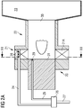
- a typical combustor - also called herewith combustion device - is shown in Fig. 2A .
- Fig. 2B is a section along a line III-III shown in Fig. 2A .
- the combustor comprises at least the following parts: a front-end part 20, a swirler part 21, a burner pre-chamber part 22 and a combustion volume 23.
- Main fuel - also called primary fuel in this document - is introduced into the swirler 21 by way of the front-end part 20 through a conduit 24, while pilot fuel - also called secondary fuel in this document - enters the burner space through a conduit 25 having at its end a pilot-fuel nozzle 29 - i.e. a secondary fuel injection point.
- the pilot-fuel nozzle may be located at a front face of a central burner 31.
- the main and pilot fuel flows are derived from a fuel-split valve 26, which is fed with a fuel supply 27 representing the total fuel supply to the combustor.
- the main fuel flow enters the swirler (21) through a set of main fuel nozzles (or injector) 28 as primary fuel injection points, from where it is guided along swirler vanes 21A, being mixed with incoming compressed air in the process.
- the resulting air and fuel mixture maintains a burner flame 30.
- the hot air and fuel mixture from this flame enters the combustion volume 23.
- FIG. 2B shows the swirler 21 with a plurality of swirler vanes 21A and a plurality of fuel injection points.
- the main fuel nozzles 28 are shown in each swirler passage between the swirler vanes 21A.
- the pilot fuel nozzle 29 - here just a single one is shown but more than pilot fuel nozzle could be present - is located in a centre region in which main fuel and air are supposed to be sufficiently mixed.
- the pilot fuel nozzle 29 can then provide an extra amount of fuel - the pilot fuel - at least in some modes of operation to stabilise the combustion.
- a gas turbine will often comprise a number of such combustors, in which case the main and pilot fuel-flow distribution will usually be as shown in Fig. 3 .
- the provided fuel may be gaseous fuel. In another embodiment the fuel may be liquid fuel.
- the fuel supply 27 - common for all combustion chambers and common for main and pilot fuel - is provided to the fuel split valve 26.
- the fuel split value 26 is controlled by a control unit and splits the fuel into a line for main fuel 50 and a line for pilot fuel 51.
- the main fuel is then - preferably in even share - provided to the number of combustion chambers present - in the figure as an example to combustion chamber 121 (indicated also as combustion chamber "#1"), combustion chamber 122 (indicated also as combustion chamber "#1”), and combustion chamber 123 (indicated also as combustion chamber "#n", as it should reflect any possible number of n combustion chambers).
- the inventive method may also be used in a further embodiment in which the primary fuel may be gaseous fuel of one type and the secondary fuel may be gaseous fuel of a second type.
- the primary fuel may be gaseous fuel of one type
- the secondary fuel may be gaseous fuel of a second type.
- the same is also possible for two different sources of liquid fuel.
- a combustor or set of combustors, where there is more than one
- a constant load imposed on the apparatus which may be, for example, a gas turbine. Where the load on the gas turbine changes, it will then be necessary to change the total fuel supply to the gas turbine, but not otherwise, normally.
- Fig. 4 which corresponds to Fig. 2A
- temperature and pressure oscillations in this combustor arrangement are measured as an example by placing, firstly, a temperature sensor 32 and, secondly, a pressure sensor 33 within the combustion volume 23.
- the outputs 34 and 35 from the two sensors 32, 33 are taken to a control unit 36 and an output 37 of the control unit controls the ratio of main and pilot fuel through the fuel split valve 26.
- the control unit 36 contains processing apparatus to carry out an algorithm suitable for keeping the operation of the gas turbine inside a wanted area, which is now explained further by reference to the further figures.
- Fig. 5 several bands of operation are shown, each band defined for a specific fuel type.
- bands 100, 100', 100", and 100''' of fuel split 101 are pre-defined and shown in the figure in relation to an engine load 102.
- the bands 100, 100', 100", and 100''' each are preset for a given Wobbe Index range of the fuel.
- the Wobbe Index range defines a range of allowable heating values for the supplied fuel.
- the Y-axis of the shown graph in Fig. 5 indicates the fuel split, which can also be defined as the amount of pilot fuel divided by the sum of the amounts of main fuel and pilot fuel.
- the X-axis may indicate the range of engine loads.
- the bands shown will generally define a higher supply of pilot fuel for low engine loads and a reduced pilot fuel supply for high engine loads.
- the bands 100, 100', 100", and 100''' overlap in parts so that two neighbouring bands have areas in which for a given load and a given Wobbe Index and a given fuel split the method can select one of the two bands as the band that should be used for control.
- Each band is defined allowable values that lie in between a pair of minimum and maximum boundary curves.
- a minimum boundary curve 100B is defined and a maximum boundary curve 100A.
- a minimum boundary curve 100B' is defined and a maximum boundary curve 100A'
- a minimum boundary curve 100B'' is defined and a maximum boundary curve 100A"
- a maximum boundary curve 100A''' is defined and a maximum boundary curve 100A''.
- a range of acceptable, tolerable and/or wanted operating points lie. What can be seen in the exemplary Fig.
- the bands 100, 100', 100'', 100''' have a clear overlap, i.e. the minimum maximum boundary curve 100B is below the maximum boundary curve 100A'. With higher loads, this overlap is reduced such that at high loads the minimum maximum boundary curve 100B may converge the maximum boundary curve 100A'.
- the maximum boundary curves 100A, 100A',... each define a maximum fuel split level for a specific engine load
- the minimum boundary curves 100B, 100B',... each define a predefined minimum fuel split level for each band.
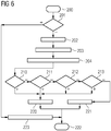
- the method is started at process step 200.
- it is tested, whether a constant fuel heating input is provided, step 201.
- fuel heating value information is retrieved - step 202.
- the retrieved information is called first information item according to the patent claims. Any parameter that correlated to the heating value of the provided fuel can be used as the first information item.
- the engine load 102 Based on the reading of the fuel heating value, and based on the engine load 102 - the engine load 102 corresponds to the second information item as defined in the claims - one of the bands 100, 100', 100", 100''' is selected - step 203.
- a pair of minimum and maximum boundary curves for the fuel split setting is selected and/or set, taken from a plurality of predefined pairs of boundary curves.
- two bands are candidates to be selected as relevant band according to which the control is performed.
- To select the more appropriate band of both potential bands possibly historical data or extrapolated future data can be evaluated.
- the most appropriate or beneficial predefined pair of minimum and maximum boundary curves for the fuel split setting is selected, selected from a plurality of predefined pairs of boundary curves.
- the selection is performed based on the first information item and the second information item.
- the minimum and maximum boundary curves define a band of fuel split settings permitted for a range of second information item values, i.e. in the example for a range of engine load values.
- the previous analysis does not always require online and continuous monitoring of fuel heating value.
- the fuel heating value may also be configured or set by an operator. Alternatively the value will be continuously monitored or read.
- step 204 following step 203, combustion dynamics pressure, emission of NOx, emission of CO, combustion device surface temperature, combustion dynamics noise emission, vibration of the combustion device, and/or flame instability is evaluated. This corresponds to the third information item according to the claims.
- a control of the fuel split setting value is performed, wherein the fuel split setting value is used to control a valve - see e.g. fuel split valve 26 in Fig. 3 or 4 .
- the fuel split setting value is adjusted according to process step 220.
- At least one of several sub routines may be executed.
- Particularly a sub routine 210 may be initiated to respond properly to combustion dynamics or pressure dynamics. If this does not require an adjustment of the fuel split setting value, a further sub module 211 may be initiated to respond properly to burner temperatures. Again, if this does not require an adjustment of the fuel split setting value, a sub module 212 may be initiated which performs action in response to emissions, such as to minimise emission.
- a further sub module 213 may be initiated to select a new band as shown in Fig. 5 , i.e. to select a fuel schedule.
- step 220 the adjustment will be performed.
- control method can terminate - step 222 - or could jump back to the start position 200.
- step 201 As previously said, as a first check it is tested, whether a constant fuel heating input is provided, see step 201.
- this improved control method can be bypassed and other control methods can be executed, step 223.
Landscapes
- Engineering & Computer Science (AREA)
- Chemical & Material Sciences (AREA)
- Combustion & Propulsion (AREA)
- Mechanical Engineering (AREA)
- General Engineering & Computer Science (AREA)
- Regulation And Control Of Combustion (AREA)
- Control Of Turbines (AREA)
- Output Control And Ontrol Of Special Type Engine (AREA)
- Feeding And Controlling Fuel (AREA)
Claims (15)
- Procédé de détermination d'une valeur (101) de réglage de la répartition des combustibles utilisable afin d'adapter un réglage de la répartition des combustibles destinés à un dispositif de combustion (12), le réglage de la répartition des combustibles définissant une relation entre un combustible principal (50) amené aux points d'injection (28) de combustible primaire et un combustible pilote (51) amené à au moins un point d'injection (29) de combustible secondaire, tous les deux étant amenés jusqu'au dispositif de combustion (12) en vue de leur combustion en un fluide brûlé, tous les deux ayant en particulier la même composition chimique, tous les deux étant en particulier un combustible gazeux,
le procédé comprenant les étapes consistant :- à récupérer un premier élément d'information corrélé à un pouvoir calorifique du combustible principal (50) amené ;- à récupérer un deuxième élément d'information corrélé à un état de fonctionnement du dispositif de combustion quand il brûle le combustible principal (50) et le combustible pilote (51), le deuxième élément d'information étant en particulier au moins un paramètre parmi une température d'allumage, une température de sortie du fluide brûlé sortant du dispositif de combustion (12), la poussée du fluide brûlé et une charge du moteur d'une machine tournante (1) située en aval du dispositif de combustion et entraînée en réaction à un écoulement du fluide brûlé, en particulier un moteur à turbine à gaz ;- à récupérer au moins un troisième élément d'information, le troisième élément d'information représentant la stabilité de la combustion dans le dispositif de combustion (12), représentant en particulier au moins un paramètre parmi la pression due à la dynamique de combustion, l'émission de NOx, l'émission de CO, la température de surface du dispositif de combustion, l'émission de bruit due à la dynamique de combustion, la vibration du dispositif de combustion (12) et l'instabilité de la flamme ;- à sélectionner parmi une pluralité de paires prédéfinies de courbes limites (100A, 100B ; 100A', 100B'...), sur la base du premier élément d'information et du deuxième élément d'information, une paire prédéfinie de courbes limites minimale et maximale (100A, 100B ; 100A', 100B'...) en vue du réglage de la répartition des combustibles, les courbes limites (100A, 100B ; 100A', 100B'...) définissant une bande de réglages de la répartition des combustibles permis pour une plage de valeurs du deuxième élément d'information, les bandes (100, 100', 100" et 100''') étant chacune préréglées pour une plage donnée d'indice de Wobbe du combustible et la plage d'indice de Wobbe définissant une gamme de pouvoirs calorifiques admissibles pour le combustible amené, et- à déterminer, sur la base du troisième élément d'information, la valeur (101) de réglage de la répartition des combustibles dans les limites de la paire sélectionnée de courbes limites minimale et maximale (100A, 100B ; 100A', 100B'...), étant entendu que la valeur (101) déterminée pour régler la répartition des combustibles est utilisable afin d'adapter le réglage de la répartition des combustibles destiné au dispositif de combustion (12). - Procédé selon la revendication 1,
comprenant par ailleurs une étape (220) de réglage d'un paramètre de régulation en vue de réguler une quantité de l'alimentation en combustible principal fournie aux points d'injection (28) de combustible primaire et/ou une quantité du combustible pilote (51) fournie au au moins un point d'injection (29) de combustible secondaire sur la base de la valeur (101) déterminée pour régler la répartition des combustibles. - Procédé selon l'une des revendications 1 et 2,
caractérisé en ce que :
au moins deux éléments sélectionnés parmi le premier élément d'information et le deuxième élément d'information et l'au moins un troisième élément d'information sont récupérés de manière synchrone. - Procédé selon l'une des revendications 1 et 2,
caractérisé en ce que :le premier élément d'information est récupéré une fois pendant un premier intervalle de temps ;le deuxième élément d'information et l'au moins un troisième élément d'information sont récupérés au moins une fois pendant un deuxième intervalle de temps, le premier intervalle de temps étant plus long que le deuxième intervalle de temps, le premier intervalle de temps étant en particulier plus long qu'une pluralité des deuxièmes intervalles de temps. - Procédé selon l'une des revendications 1 à 4,
caractérisé en ce que :
le premier élément d'information est récupéré en réaction à un changement de composition du combustible principal (50) amené et/ou du combustible pilote (51) amené, et/ou en ce que le premier élément d'information est récupéré en réaction à un basculement vers une source différente du combustible principal (50) amené et/ou du combustible pilote (51) amené. - Procédé selon l'une des revendications 1 à 5,
caractérisé en ce que :
l'étape (220) consistant à déterminer la valeur (101) de réglage de la répartition des combustibles est exécutée en continu ou en réaction à une modification du deuxième élément d'information et/ou à une modification de l'au moins un troisième élément d'information. - Procédé selon l'une des revendications 1 à 6,
caractérisé en ce que :
en vue de la récupération du premier article d'information, le pouvoir calorifique du combustible principal (50) amené et/ou le pouvoir calorifique du combustible pilote (51) amené est déterminé au moyen d'un signal de capteur. - Procédé selon l'une des revendications 1 à 7,
caractérisé en ce que :
en vue de la récupération du deuxième élément d'information :- la température d'allumage, la température de sortie du fluide brûlé sortant du dispositif de combustion (12), la poussée du fluide brûlé, une température d'entrée de turbine d'une section formant turbine de la machine tournante (1) est déterminée au moyen d'un signal de capteur ou calculée sur la base d'au moins un signal de capteur, ou- la charge (102) du moteur de la machine tournante (1) est déterminée au moyen d'un indicateur de charge par évaluation du couple d'un arbre (2) et/ou de la vitesse de rotation de l'arbre (2) de la machine tournante (1) entraînée en réaction à la combustion assurée par le dispositif de combustion (12). - Procédé selon l'une des revendications 1 à 8,
caractérisé en ce que :
en vue de la récupération de l'au moins un troisième élément d'information, on évalue au moins un signal de capteur, le signal de capteur représentant au moins un paramètre parmi la pression due à la dynamique de combustion, l'émission de NOx, l'émission de CO, la température de surface du dispositif de combustion, l'émission de bruit, la vibration du dispositif de combustion (12), une température des gaz de combustion et un défaut de la flamme. - Procédé selon l'une des revendications 1 à 9,
caractérisé en ce que :la paire prédéfinie de courbes limites minimale et maximale (100A, 100B ; 100A', 100B'...) pour le réglage de la répartition des combustibles est définie au moins par un niveau maximal prédéfini de répartition des combustibles et un niveau minimal prédéfini de répartition des combustibles fournis sur une plage de valeurs du deuxième élément d'information, etle niveau maximal de répartition des combustibles représentant la relation entre le combustible pilote (51) et le combustible principal (50) avec le pourcentage tolérable le plus élevé du combustible pilote (51) par rapport au combustible principal (50), etle niveau minimal de répartition des combustibles représentant la relation entre le combustible pilote (51) et le combustible principal (50) avec le pourcentage tolérable le plus bas du combustible pilote (51) par rapport au combustible principal (50) . - Procédé selon l'une des revendications 1 à 10,
comprenant par ailleurs une étape de sélection d'un procédé prédéfini (201, 211, 212, 213) de logique de régulation parmi une pluralité de procédés prédéfinis (201, 211, 212, 213) de logique de régulation sur la base du premier élément d'information et/ou du deuxième élément d'information et/ou du troisième élément d'information, étant entendu que l'on réalise l'étape de détermination de la valeur (101) de réglage de la répartition des combustibles en exécutant le procédé sélectionné (201, 211, 212, 213) de logique de régulation. - Unité (36) de régulation de dispositif de combustion servant à déterminer une valeur (101) de réglage de la répartition des combustibles utilisable afin d'adapter un réglage de la répartition des combustibles destiné à un dispositif de combustion (12), le réglage de la répartition des combustibles définissant une répartition d'une alimentation en combustible principal fournie en des points d'injection (28) de combustible primaire et d'une alimentation en combustible pilote fournie en au moins un point d'injection (29) de combustible secondaire, tous deux pouvant être fournis au dispositif de combustion (12) en vue de leur combustion en un fluide brûlé, l'unité (36) de régulation du dispositif de combustion étant en particulier agencée pour que le combustible principal (50) et le combustible pilote (51) aient tous les deux la même composition chimique et/ou pour qu'ils soient tous les deux un combustible gazeux, l'unité de régulation du dispositif de combustion comprenant :- un premier composant de récupération de données servant à récupérer un premier élément d'information corrélé à un pouvoir calorifique du combustible primaire ou combustible principal (50) amené ;- un deuxième composant de récupération de données servant à récupérer un deuxième élément d'information corrélé à un état de fonctionnement du dispositif de combustion quand il brûle le combustible principal (50) et le combustible pilote (51), le deuxième élément d'information étant en particulier au moins un paramètre parmi une température d'allumage, une température de sortie du fluide brûlé sortant du dispositif de combustion (12), la poussée du fluide brûlé et une charge du moteur d'une machine tournante (1) située en aval du dispositif de combustion et entraînée en réaction à un écoulement du fluide brûlé, en particulier un moteur à turbine à gaz ;- un troisième composant de récupération de données servant à récupérer au moins un troisième élément d'information, le troisième élément d'information représentant la stabilité de la combustion dans le dispositif de combustion (12), représentant en particulier au moins un paramètre parmi la pression due à la dynamique de combustion, l'émission de NOx, l'émission de CO, la température de surface du dispositif de combustion, l'émission de bruit due à la dynamique de combustion, la vibration du dispositif de combustion (12) et l'instabilité de la flamme ;- un composant de sélection servant à sélectionner, sur la base du premier élément d'information et du deuxième élément d'information, une paire prédéfinie de courbes limites minimale et maximale (100A, 100B ; 100A', 100B'...) pour le réglage de la répartition des combustibles parmi une pluralité de paires prédéfinies de courbes limites (100A, 100B ; 100A', 100B'...), les courbes limites (100A, 100B ; 100A', 100B'...) définissant une bande de réglages de la répartition des combustibles (100, 100', ...) permis pour une plage de valeurs du deuxième élément d'information, les bandes (100, 100', 100" et 100"') étant chacune préréglées pour une plage donnée d'indice de Wobbe du combustible et la plage d'indice de Wobbe définissant une gamme de pouvoirs calorifiques admissibles pour le combustible amené, et- une unité de détermination servant à déterminer, sur la base du troisième élément d'information, la valeur (101) de réglage de la répartition des combustibles dans les limites de la paire sélectionnée de courbes limites minimale et maximale (100A, 100B ; 100A', 100B'...), étant entendu que la valeur (101) de réglage de la répartition des combustibles déterminée est utilisable afin d'adapter le réglage de la répartition des combustibles destiné au dispositif de combustion (12).
- Unité (36) de régulation de dispositif de combustion selon la revendication 12,
caractérisée en ce que :
l'unité (36) de régulation de dispositif de combustion comprend un composant d'entrée de capteur servant à collecter des informations provenant de capteurs, les capteurs fournissant des informations relatives :- au pouvoir calorifique du combustible principal (50) amené et/ou à un pouvoir calorifique d'un combustible pilote (51) amené, et/ou- à l'état de fonctionnement du dispositif de combustion, en particulier à la température d'allumage, à la température de sortie du fluide brûlé sortant du dispositif de combustion (12), à la poussée du fluide brûlé ou à la charge du moteur d'une machine tournante (1) qui est entraînée en réaction à un écoulement du fluide brûlé, et/ou- à la pression due à la dynamique de combustion et/ou à l'émission de NOx et/ou à l'émission de CO et/ou à la température de surface du dispositif de combustion et/ou à l'émission de bruit et/ou à la vibration du dispositif de combustion (12) et/ou à la défaillance de la flamme. - Unité (36) de régulation de dispositif de combustion selon l'une des revendications 12 et 13,
caractérisée en ce que :
l'unité (36) de régulation de dispositif de combustion comprend une interface de sortie de régulation servant à régler un paramètre de régulation en vue de réguler, en particulier au moyen d'une ou de plusieurs vannes (26), une quantité de combustible principal (50) et/ou une quantité de combustible pilote (51) à amener jusqu'au dispositif de combustion (12) sur la base de la valeur (101) déterminée pour régler la répartition des combustibles. - Machine tournante (1), en particulier un moteur à turbine à gaz, comprenant :- un dispositif de combustion (12) ;- une unité (36) de régulation de dispositif de combustion selon l'une des revendications 12 à 14 pour réguler la valeur (101) de réglage de la répartition des combustibles du dispositif de combustion (12) ;- un arbre (2), et- une section formant turbine (3) en aval du dispositif de combustion (12) en vue d'entraîner l'arbre (2) en rotation en réaction à un fluide brûlé amené depuis le dispositif de combustion (12) jusqu'à la section formant turbine (3) pendant son fonctionnement.
Applications Claiming Priority (2)
| Application Number | Priority Date | Filing Date | Title |
|---|---|---|---|
| EP14170793.5A EP2952811A1 (fr) | 2014-06-02 | 2014-06-02 | Procédé et dispositif pour commander une division de combustible dans un dispositif de combustion |
| PCT/EP2015/061712 WO2015185413A1 (fr) | 2014-06-02 | 2015-05-27 | Procédé et dispositif de commande de partage de combustible dans un dispositif de combustion |
Publications (2)
| Publication Number | Publication Date |
|---|---|
| EP3129711A1 EP3129711A1 (fr) | 2017-02-15 |
| EP3129711B1 true EP3129711B1 (fr) | 2020-04-22 |
Family
ID=50884266
Family Applications (2)
| Application Number | Title | Priority Date | Filing Date |
|---|---|---|---|
| EP14170793.5A Withdrawn EP2952811A1 (fr) | 2014-06-02 | 2014-06-02 | Procédé et dispositif pour commander une division de combustible dans un dispositif de combustion |
| EP15727917.5A Active EP3129711B1 (fr) | 2014-06-02 | 2015-05-27 | Procédé et dispositif pour commander une division de combustible dans un dispositif de combustion |
Family Applications Before (1)
| Application Number | Title | Priority Date | Filing Date |
|---|---|---|---|
| EP14170793.5A Withdrawn EP2952811A1 (fr) | 2014-06-02 | 2014-06-02 | Procédé et dispositif pour commander une division de combustible dans un dispositif de combustion |
Country Status (5)
| Country | Link |
|---|---|
| US (1) | US11434825B2 (fr) |
| EP (2) | EP2952811A1 (fr) |
| CN (1) | CN106415129B (fr) |
| RU (1) | RU2654809C1 (fr) |
| WO (1) | WO2015185413A1 (fr) |
Families Citing this family (9)
| Publication number | Priority date | Publication date | Assignee | Title |
|---|---|---|---|---|
| US11953201B2 (en) * | 2013-02-14 | 2024-04-09 | Clearsign Technologies Corporation | Control system and method for a burner with a distal flame holder |
| US10006330B2 (en) * | 2014-10-28 | 2018-06-26 | General Electric Company | System and method for emissions control in gas turbine systems |
| WO2017140906A1 (fr) * | 2016-02-19 | 2017-08-24 | Haldor Topsøe A/S | Protection contre l'emballement d'une unité de de combustion |
| US11408356B2 (en) * | 2017-10-03 | 2022-08-09 | General Electric Company | Method of operating a combustion system with main and pilot fuel circuits |
| EP3530912A1 (fr) | 2018-02-23 | 2019-08-28 | Siemens Aktiengesellschaft | Organe de commande et procédé |
| EP3530913A1 (fr) | 2018-02-23 | 2019-08-28 | Siemens Aktiengesellschaft | Organe de commande et procédé |
| US20210003072A1 (en) * | 2018-12-04 | 2021-01-07 | Look For The Power, Llc | Rotary internal combustion engine |
| GB202201985D0 (en) * | 2022-02-15 | 2022-03-30 | Rolls Royce Plc | Engine system and method of operating the same |
| GB202205345D0 (en) * | 2022-04-12 | 2022-05-25 | Rolls Royce Plc | Engine parameters |
Family Cites Families (14)
| Publication number | Priority date | Publication date | Assignee | Title |
|---|---|---|---|---|
| DE19549108A1 (de) | 1995-12-29 | 1997-07-03 | Bosch Gmbh Robert | System zur Kraftstoffhochdruckerzeugung für ein in Brennkraftmaschinen eingesetztes Kraftstoffeinspritzsystem |
| RU2189476C2 (ru) * | 2000-11-08 | 2002-09-20 | Государственное унитарное предприятие "АВИАГАЗ-СОЮЗ" (дочернее предприятие КОКБ "СОЮЗ") | Передвижная электростанция |
| EP1524423A1 (fr) * | 2003-10-13 | 2005-04-20 | Siemens Aktiengesellschaft | Procédé et dispositif pour niveler la fluctuation de la composition du carburant dans une turbine à gaz |
| GB0515034D0 (en) * | 2005-07-21 | 2005-08-31 | Rolls Royce Plc | Method and system for operating a multi-stage combustor |
| US7549292B2 (en) * | 2005-10-03 | 2009-06-23 | General Electric Company | Method of controlling bypass air split to gas turbine combustor |
| US7565805B2 (en) * | 2005-11-22 | 2009-07-28 | General Electric Company | Method for operating gas turbine engine systems |
| GB2434437B (en) | 2006-01-19 | 2011-01-26 | Siemens Ag | Improvements in or relating to combustion apparatus |
| JP4831820B2 (ja) * | 2006-05-22 | 2011-12-07 | 三菱重工業株式会社 | ガスタービン出力学習回路及びこれを備えたガスタービンの燃焼制御装置 |
| US8356484B2 (en) * | 2009-05-01 | 2013-01-22 | General Electric Company | Hybrid Wobbe control during rapid response startup |
| BR112012010811A2 (pt) * | 2009-10-09 | 2016-04-05 | Siemens Ag | aparelho de combustão |
| IT1396517B1 (it) * | 2009-11-27 | 2012-12-14 | Nuovo Pignone Spa | Metodo di controllo di modo basato su temperatura di scarico per turbina a gas e turbina a gas |
| IT1396516B1 (it) * | 2009-11-27 | 2012-12-14 | Nuovo Pignone Spa | Metodo di controllo di modo basato su temperatura di scarico per turbina a gas e turbina a gas |
| US8417433B2 (en) * | 2010-04-30 | 2013-04-09 | Alstom Technology Ltd. | Dynamically auto-tuning a gas turbine engine |
| US20120102914A1 (en) * | 2010-11-03 | 2012-05-03 | General Electric Company | Systems, methods, and apparatus for compensating fuel composition variations in a gas turbine |
-
2014
- 2014-06-02 EP EP14170793.5A patent/EP2952811A1/fr not_active Withdrawn
-
2015
- 2015-05-27 US US15/311,934 patent/US11434825B2/en active Active
- 2015-05-27 CN CN201580029318.5A patent/CN106415129B/zh active Active
- 2015-05-27 RU RU2016151781A patent/RU2654809C1/ru active
- 2015-05-27 WO PCT/EP2015/061712 patent/WO2015185413A1/fr not_active Ceased
- 2015-05-27 EP EP15727917.5A patent/EP3129711B1/fr active Active
Non-Patent Citations (1)
| Title |
|---|
| None * |
Also Published As
| Publication number | Publication date |
|---|---|
| EP2952811A1 (fr) | 2015-12-09 |
| WO2015185413A1 (fr) | 2015-12-10 |
| CN106415129B (zh) | 2019-09-24 |
| EP3129711A1 (fr) | 2017-02-15 |
| RU2654809C1 (ru) | 2018-05-22 |
| US11434825B2 (en) | 2022-09-06 |
| CN106415129A (zh) | 2017-02-15 |
| US20170089266A1 (en) | 2017-03-30 |
Similar Documents
| Publication | Publication Date | Title |
|---|---|---|
| US11434825B2 (en) | Method and device to control a fuel split in a combustion device | |
| US6195607B1 (en) | Method and apparatus for optimizing NOx emissions in a gas turbine | |
| EP3069083B1 (fr) | Procédé de commande intelligent avec capacité de surveillance prédictive des émissions pour une chambre de combustion de turbine à gaz | |
| US7513100B2 (en) | Systems for low emission gas turbine energy generation | |
| CN1971013B (zh) | 用于操作燃气轮机系统的方法和装置 | |
| US8122725B2 (en) | Methods and systems for operating gas turbine engines | |
| WO2011042037A1 (fr) | Appareil de combustion | |
| US20170356342A1 (en) | Circuit-level heating for wide wobbe fuels in dln gas turbine combustion | |
| US11746712B2 (en) | Controller and method | |
| EP3685027A1 (fr) | Unité de commande et procédé | |
| EP3324118B1 (fr) | Système de commande d'émission à charge partielle faible pour système de combustion de système de turbine à gaz | |
| US11655769B2 (en) | Controller and method for controlling a gas turbine | |
| US20140182297A1 (en) | Gas turbine and method of controlling a gas turbine at part-load condition | |
| US11085646B2 (en) | Technique for controlling operating point of a combustion system by using pilot-air | |
| CN109210572B (zh) | 用于燃气涡轮的顺序燃烧器的第二级燃烧器 | |
| US11525409B2 (en) | Temperature based gas turbine control and method | |
| CN108119237B (zh) | 无模型燃烧动力自动调谐 | |
| JP7682655B2 (ja) | ガスタービンエンジンおよびガスタービンエンジンからの排出物を制御する方法 | |
| US10180107B2 (en) | System and method for adjusting combustor fuel split |
Legal Events
| Date | Code | Title | Description |
|---|---|---|---|
| STAA | Information on the status of an ep patent application or granted ep patent |
Free format text: STATUS: THE INTERNATIONAL PUBLICATION HAS BEEN MADE |
|
| PUAI | Public reference made under article 153(3) epc to a published international application that has entered the european phase |
Free format text: ORIGINAL CODE: 0009012 |
|
| STAA | Information on the status of an ep patent application or granted ep patent |
Free format text: STATUS: REQUEST FOR EXAMINATION WAS MADE |
|
| 17P | Request for examination filed |
Effective date: 20161109 |
|
| AK | Designated contracting states |
Kind code of ref document: A1 Designated state(s): AL AT BE BG CH CY CZ DE DK EE ES FI FR GB GR HR HU IE IS IT LI LT LU LV MC MK MT NL NO PL PT RO RS SE SI SK SM TR |
|
| AX | Request for extension of the european patent |
Extension state: BA ME |
|
| RAP1 | Party data changed (applicant data changed or rights of an application transferred) |
Owner name: SIEMENS AKTIENGESELLSCHAFT |
|
| DAV | Request for validation of the european patent (deleted) | ||
| DAX | Request for extension of the european patent (deleted) | ||
| STAA | Information on the status of an ep patent application or granted ep patent |
Free format text: STATUS: EXAMINATION IS IN PROGRESS |
|
| 17Q | First examination report despatched |
Effective date: 20190221 |
|
| GRAP | Despatch of communication of intention to grant a patent |
Free format text: ORIGINAL CODE: EPIDOSNIGR1 |
|
| STAA | Information on the status of an ep patent application or granted ep patent |
Free format text: STATUS: GRANT OF PATENT IS INTENDED |
|
| INTG | Intention to grant announced |
Effective date: 20191216 |
|
| GRAS | Grant fee paid |
Free format text: ORIGINAL CODE: EPIDOSNIGR3 |
|
| GRAA | (expected) grant |
Free format text: ORIGINAL CODE: 0009210 |
|
| STAA | Information on the status of an ep patent application or granted ep patent |
Free format text: STATUS: THE PATENT HAS BEEN GRANTED |
|
| AK | Designated contracting states |
Kind code of ref document: B1 Designated state(s): AL AT BE BG CH CY CZ DE DK EE ES FI FR GB GR HR HU IE IS IT LI LT LU LV MC MK MT NL NO PL PT RO RS SE SI SK SM TR |
|
| REG | Reference to a national code |
Ref country code: CH Ref legal event code: EP |
|
| REG | Reference to a national code |
Ref country code: IE Ref legal event code: FG4D |
|
| REG | Reference to a national code |
Ref country code: DE Ref legal event code: R096 Ref document number: 602015051133 Country of ref document: DE |
|
| REG | Reference to a national code |
Ref country code: AT Ref legal event code: REF Ref document number: 1260608 Country of ref document: AT Kind code of ref document: T Effective date: 20200515 |
|
| REG | Reference to a national code |
Ref country code: LT Ref legal event code: MG4D |
|
| REG | Reference to a national code |
Ref country code: NL Ref legal event code: MP Effective date: 20200422 |
|
| PG25 | Lapsed in a contracting state [announced via postgrant information from national office to epo] |
Ref country code: SE Free format text: LAPSE BECAUSE OF FAILURE TO SUBMIT A TRANSLATION OF THE DESCRIPTION OR TO PAY THE FEE WITHIN THE PRESCRIBED TIME-LIMIT Effective date: 20200422 Ref country code: NL Free format text: LAPSE BECAUSE OF FAILURE TO SUBMIT A TRANSLATION OF THE DESCRIPTION OR TO PAY THE FEE WITHIN THE PRESCRIBED TIME-LIMIT Effective date: 20200422 Ref country code: FI Free format text: LAPSE BECAUSE OF FAILURE TO SUBMIT A TRANSLATION OF THE DESCRIPTION OR TO PAY THE FEE WITHIN THE PRESCRIBED TIME-LIMIT Effective date: 20200422 Ref country code: IS Free format text: LAPSE BECAUSE OF FAILURE TO SUBMIT A TRANSLATION OF THE DESCRIPTION OR TO PAY THE FEE WITHIN THE PRESCRIBED TIME-LIMIT Effective date: 20200822 Ref country code: GR Free format text: LAPSE BECAUSE OF FAILURE TO SUBMIT A TRANSLATION OF THE DESCRIPTION OR TO PAY THE FEE WITHIN THE PRESCRIBED TIME-LIMIT Effective date: 20200723 Ref country code: NO Free format text: LAPSE BECAUSE OF FAILURE TO SUBMIT A TRANSLATION OF THE DESCRIPTION OR TO PAY THE FEE WITHIN THE PRESCRIBED TIME-LIMIT Effective date: 20200722 Ref country code: PT Free format text: LAPSE BECAUSE OF FAILURE TO SUBMIT A TRANSLATION OF THE DESCRIPTION OR TO PAY THE FEE WITHIN THE PRESCRIBED TIME-LIMIT Effective date: 20200824 Ref country code: LT Free format text: LAPSE BECAUSE OF FAILURE TO SUBMIT A TRANSLATION OF THE DESCRIPTION OR TO PAY THE FEE WITHIN THE PRESCRIBED TIME-LIMIT Effective date: 20200422 |
|
| REG | Reference to a national code |
Ref country code: AT Ref legal event code: MK05 Ref document number: 1260608 Country of ref document: AT Kind code of ref document: T Effective date: 20200422 |
|
| PG25 | Lapsed in a contracting state [announced via postgrant information from national office to epo] |
Ref country code: LV Free format text: LAPSE BECAUSE OF FAILURE TO SUBMIT A TRANSLATION OF THE DESCRIPTION OR TO PAY THE FEE WITHIN THE PRESCRIBED TIME-LIMIT Effective date: 20200422 Ref country code: RS Free format text: LAPSE BECAUSE OF FAILURE TO SUBMIT A TRANSLATION OF THE DESCRIPTION OR TO PAY THE FEE WITHIN THE PRESCRIBED TIME-LIMIT Effective date: 20200422 Ref country code: BG Free format text: LAPSE BECAUSE OF FAILURE TO SUBMIT A TRANSLATION OF THE DESCRIPTION OR TO PAY THE FEE WITHIN THE PRESCRIBED TIME-LIMIT Effective date: 20200722 Ref country code: HR Free format text: LAPSE BECAUSE OF FAILURE TO SUBMIT A TRANSLATION OF THE DESCRIPTION OR TO PAY THE FEE WITHIN THE PRESCRIBED TIME-LIMIT Effective date: 20200422 |
|
| REG | Reference to a national code |
Ref country code: DE Ref legal event code: R081 Ref document number: 602015051133 Country of ref document: DE Owner name: SIEMENS ENERGY GLOBAL GMBH & CO. KG, DE Free format text: FORMER OWNER: SIEMENS AKTIENGESELLSCHAFT, 80333 MUENCHEN, DE |
|
| PG25 | Lapsed in a contracting state [announced via postgrant information from national office to epo] |
Ref country code: AL Free format text: LAPSE BECAUSE OF FAILURE TO SUBMIT A TRANSLATION OF THE DESCRIPTION OR TO PAY THE FEE WITHIN THE PRESCRIBED TIME-LIMIT Effective date: 20200422 |
|
| REG | Reference to a national code |
Ref country code: DE Ref legal event code: R097 Ref document number: 602015051133 Country of ref document: DE |
|
| RAP2 | Party data changed (patent owner data changed or rights of a patent transferred) |
Owner name: SIEMENS ENERGY GLOBAL GMBH & CO. KG |
|
| PG25 | Lapsed in a contracting state [announced via postgrant information from national office to epo] |
Ref country code: RO Free format text: LAPSE BECAUSE OF FAILURE TO SUBMIT A TRANSLATION OF THE DESCRIPTION OR TO PAY THE FEE WITHIN THE PRESCRIBED TIME-LIMIT Effective date: 20200422 Ref country code: CH Free format text: LAPSE BECAUSE OF NON-PAYMENT OF DUE FEES Effective date: 20200531 Ref country code: CZ Free format text: LAPSE BECAUSE OF FAILURE TO SUBMIT A TRANSLATION OF THE DESCRIPTION OR TO PAY THE FEE WITHIN THE PRESCRIBED TIME-LIMIT Effective date: 20200422 Ref country code: SM Free format text: LAPSE BECAUSE OF FAILURE TO SUBMIT A TRANSLATION OF THE DESCRIPTION OR TO PAY THE FEE WITHIN THE PRESCRIBED TIME-LIMIT Effective date: 20200422 Ref country code: EE Free format text: LAPSE BECAUSE OF FAILURE TO SUBMIT A TRANSLATION OF THE DESCRIPTION OR TO PAY THE FEE WITHIN THE PRESCRIBED TIME-LIMIT Effective date: 20200422 Ref country code: DK Free format text: LAPSE BECAUSE OF FAILURE TO SUBMIT A TRANSLATION OF THE DESCRIPTION OR TO PAY THE FEE WITHIN THE PRESCRIBED TIME-LIMIT Effective date: 20200422 Ref country code: AT Free format text: LAPSE BECAUSE OF FAILURE TO SUBMIT A TRANSLATION OF THE DESCRIPTION OR TO PAY THE FEE WITHIN THE PRESCRIBED TIME-LIMIT Effective date: 20200422 Ref country code: MC Free format text: LAPSE BECAUSE OF FAILURE TO SUBMIT A TRANSLATION OF THE DESCRIPTION OR TO PAY THE FEE WITHIN THE PRESCRIBED TIME-LIMIT Effective date: 20200422 Ref country code: LI Free format text: LAPSE BECAUSE OF NON-PAYMENT OF DUE FEES Effective date: 20200531 Ref country code: ES Free format text: LAPSE BECAUSE OF FAILURE TO SUBMIT A TRANSLATION OF THE DESCRIPTION OR TO PAY THE FEE WITHIN THE PRESCRIBED TIME-LIMIT Effective date: 20200422 |
|
| PG25 | Lapsed in a contracting state [announced via postgrant information from national office to epo] |
Ref country code: SK Free format text: LAPSE BECAUSE OF FAILURE TO SUBMIT A TRANSLATION OF THE DESCRIPTION OR TO PAY THE FEE WITHIN THE PRESCRIBED TIME-LIMIT Effective date: 20200422 Ref country code: PL Free format text: LAPSE BECAUSE OF FAILURE TO SUBMIT A TRANSLATION OF THE DESCRIPTION OR TO PAY THE FEE WITHIN THE PRESCRIBED TIME-LIMIT Effective date: 20200422 |
|
| PLBE | No opposition filed within time limit |
Free format text: ORIGINAL CODE: 0009261 |
|
| STAA | Information on the status of an ep patent application or granted ep patent |
Free format text: STATUS: NO OPPOSITION FILED WITHIN TIME LIMIT |
|
| REG | Reference to a national code |
Ref country code: BE Ref legal event code: MM Effective date: 20200531 |
|
| 26N | No opposition filed |
Effective date: 20210125 |
|
| PG25 | Lapsed in a contracting state [announced via postgrant information from national office to epo] |
Ref country code: LU Free format text: LAPSE BECAUSE OF NON-PAYMENT OF DUE FEES Effective date: 20200527 |
|
| PG25 | Lapsed in a contracting state [announced via postgrant information from national office to epo] |
Ref country code: IE Free format text: LAPSE BECAUSE OF NON-PAYMENT OF DUE FEES Effective date: 20200527 |
|
| PG25 | Lapsed in a contracting state [announced via postgrant information from national office to epo] |
Ref country code: BE Free format text: LAPSE BECAUSE OF NON-PAYMENT OF DUE FEES Effective date: 20200531 Ref country code: SI Free format text: LAPSE BECAUSE OF FAILURE TO SUBMIT A TRANSLATION OF THE DESCRIPTION OR TO PAY THE FEE WITHIN THE PRESCRIBED TIME-LIMIT Effective date: 20200422 |
|
| REG | Reference to a national code |
Ref country code: GB Ref legal event code: 732E Free format text: REGISTERED BETWEEN 20211202 AND 20211209 |
|
| PG25 | Lapsed in a contracting state [announced via postgrant information from national office to epo] |
Ref country code: TR Free format text: LAPSE BECAUSE OF FAILURE TO SUBMIT A TRANSLATION OF THE DESCRIPTION OR TO PAY THE FEE WITHIN THE PRESCRIBED TIME-LIMIT Effective date: 20200422 Ref country code: MT Free format text: LAPSE BECAUSE OF FAILURE TO SUBMIT A TRANSLATION OF THE DESCRIPTION OR TO PAY THE FEE WITHIN THE PRESCRIBED TIME-LIMIT Effective date: 20200422 Ref country code: CY Free format text: LAPSE BECAUSE OF FAILURE TO SUBMIT A TRANSLATION OF THE DESCRIPTION OR TO PAY THE FEE WITHIN THE PRESCRIBED TIME-LIMIT Effective date: 20200422 |
|
| PG25 | Lapsed in a contracting state [announced via postgrant information from national office to epo] |
Ref country code: MK Free format text: LAPSE BECAUSE OF FAILURE TO SUBMIT A TRANSLATION OF THE DESCRIPTION OR TO PAY THE FEE WITHIN THE PRESCRIBED TIME-LIMIT Effective date: 20200422 |
|
| P01 | Opt-out of the competence of the unified patent court (upc) registered |
Effective date: 20231222 |
|
| PGFP | Annual fee paid to national office [announced via postgrant information from national office to epo] |
Ref country code: DE Payment date: 20250528 Year of fee payment: 11 |
|
| PGFP | Annual fee paid to national office [announced via postgrant information from national office to epo] |
Ref country code: IT Payment date: 20250522 Year of fee payment: 11 |
|
| PGFP | Annual fee paid to national office [announced via postgrant information from national office to epo] |
Ref country code: FR Payment date: 20250526 Year of fee payment: 11 |
|
| PGFP | Annual fee paid to national office [announced via postgrant information from national office to epo] |
Ref country code: GB Payment date: 20260323 Year of fee payment: 12 |