EP3129726B1 - Structure porteuse pour panneaux solaires - Google Patents
Structure porteuse pour panneaux solaires Download PDFInfo
- Publication number
- EP3129726B1 EP3129726B1 EP14741680.4A EP14741680A EP3129726B1 EP 3129726 B1 EP3129726 B1 EP 3129726B1 EP 14741680 A EP14741680 A EP 14741680A EP 3129726 B1 EP3129726 B1 EP 3129726B1
- Authority
- EP
- European Patent Office
- Prior art keywords
- solar panels
- pylons
- support structure
- panels
- solar
- Prior art date
- Legal status (The legal status is an assumption and is not a legal conclusion. Google has not performed a legal analysis and makes no representation as to the accuracy of the status listed.)
- Active
Links
Images



Classifications
-
- F—MECHANICAL ENGINEERING; LIGHTING; HEATING; WEAPONS; BLASTING
- F24—HEATING; RANGES; VENTILATING
- F24S—SOLAR HEAT COLLECTORS; SOLAR HEAT SYSTEMS
- F24S30/00—Arrangements for moving or orienting solar heat collector modules
- F24S30/40—Arrangements for moving or orienting solar heat collector modules for rotary movement
- F24S30/45—Arrangements for moving or orienting solar heat collector modules for rotary movement with two rotation axes
- F24S30/458—Arrangements for moving or orienting solar heat collector modules for rotary movement with two rotation axes with inclined primary axis
-
- F—MECHANICAL ENGINEERING; LIGHTING; HEATING; WEAPONS; BLASTING
- F24—HEATING; RANGES; VENTILATING
- F24S—SOLAR HEAT COLLECTORS; SOLAR HEAT SYSTEMS
- F24S30/00—Arrangements for moving or orienting solar heat collector modules
- F24S30/40—Arrangements for moving or orienting solar heat collector modules for rotary movement
- F24S30/45—Arrangements for moving or orienting solar heat collector modules for rotary movement with two rotation axes
- F24S30/452—Vertical primary axis
-
- F—MECHANICAL ENGINEERING; LIGHTING; HEATING; WEAPONS; BLASTING
- F24—HEATING; RANGES; VENTILATING
- F24S—SOLAR HEAT COLLECTORS; SOLAR HEAT SYSTEMS
- F24S20/00—Solar heat collectors specially adapted for particular uses or environments
- F24S2020/10—Solar modules layout; Modular arrangements
- F24S2020/16—Preventing shading effects
-
- F—MECHANICAL ENGINEERING; LIGHTING; HEATING; WEAPONS; BLASTING
- F24—HEATING; RANGES; VENTILATING
- F24S—SOLAR HEAT COLLECTORS; SOLAR HEAT SYSTEMS
- F24S30/00—Arrangements for moving or orienting solar heat collector modules
- F24S2030/10—Special components
- F24S2030/14—Movement guiding means
- F24S2030/145—Tracks
-
- Y—GENERAL TAGGING OF NEW TECHNOLOGICAL DEVELOPMENTS; GENERAL TAGGING OF CROSS-SECTIONAL TECHNOLOGIES SPANNING OVER SEVERAL SECTIONS OF THE IPC; TECHNICAL SUBJECTS COVERED BY FORMER USPC CROSS-REFERENCE ART COLLECTIONS [XRACs] AND DIGESTS
- Y02—TECHNOLOGIES OR APPLICATIONS FOR MITIGATION OR ADAPTATION AGAINST CLIMATE CHANGE
- Y02B—CLIMATE CHANGE MITIGATION TECHNOLOGIES RELATED TO BUILDINGS, e.g. HOUSING, HOUSE APPLIANCES OR RELATED END-USER APPLICATIONS
- Y02B10/00—Integration of renewable energy sources in buildings
- Y02B10/20—Solar thermal
-
- Y—GENERAL TAGGING OF NEW TECHNOLOGICAL DEVELOPMENTS; GENERAL TAGGING OF CROSS-SECTIONAL TECHNOLOGIES SPANNING OVER SEVERAL SECTIONS OF THE IPC; TECHNICAL SUBJECTS COVERED BY FORMER USPC CROSS-REFERENCE ART COLLECTIONS [XRACs] AND DIGESTS
- Y02—TECHNOLOGIES OR APPLICATIONS FOR MITIGATION OR ADAPTATION AGAINST CLIMATE CHANGE
- Y02E—REDUCTION OF GREENHOUSE GAS [GHG] EMISSIONS, RELATED TO ENERGY GENERATION, TRANSMISSION OR DISTRIBUTION
- Y02E10/00—Energy generation through renewable energy sources
- Y02E10/40—Solar thermal energy, e.g. solar towers
- Y02E10/47—Mountings or tracking
-
- Y—GENERAL TAGGING OF NEW TECHNOLOGICAL DEVELOPMENTS; GENERAL TAGGING OF CROSS-SECTIONAL TECHNOLOGIES SPANNING OVER SEVERAL SECTIONS OF THE IPC; TECHNICAL SUBJECTS COVERED BY FORMER USPC CROSS-REFERENCE ART COLLECTIONS [XRACs] AND DIGESTS
- Y02—TECHNOLOGIES OR APPLICATIONS FOR MITIGATION OR ADAPTATION AGAINST CLIMATE CHANGE
- Y02E—REDUCTION OF GREENHOUSE GAS [GHG] EMISSIONS, RELATED TO ENERGY GENERATION, TRANSMISSION OR DISTRIBUTION
- Y02E10/00—Energy generation through renewable energy sources
- Y02E10/50—Photovoltaic [PV] energy
Definitions
- the present invention generally relates to a structure for supporting solar panels and more particularly the invention relates to a support structure with variable geometry, which is able to move the solar panels as sun followers during the day and during the year; furthermore, the support structure is mounted on poles, as an isolated structure, or used as a cover, such as a roof of buildings or a roof of greenhouses, or installed on roundabouts or other circular-shaped surfaces.
- solatr panels are constituted by a central pillar on which a "sail” consisting of modular panels lying on the same plane is engaged.
- the central pillar is connected to a slewing ring that provides for the azimuthal movement, from east to west, of the whole structure, while a hinge, which is placed on the horizontal axis of the "sail", provides for the zenithal movement from 0 to 90°.
- Said known support structure is extremely cumbersome when many solar panels are installed and causes significant shading if there are more rows of solar trackers; moreover, each solar tracker, as described, cannot be used as a cover or roof for buildings.
- the above mentioned structure on one hand, has good features of scalability for industrial production, but, on the other hand, it needs a lot of space in order that the adjacent solar trackers do not cause unwanted shading.
- the ratio between the installed electrical power and the total surface of the structure is very high, while the ratio between the installed electrical power and the employed means, both in terms of energy needed for making the whole structure and in terms of materials constituting said structure itself (such as the steel required to build a solar tracker, the cement to perform foundations of the electrical connections, the employed workers, etc.), is very low.
- the surface which is occupied by said known supporting structure is related to the specific solar tracker and it cannot be used for any other human activity; it follows that, when the size of the single solar tracker becomes greater, the whole supporting structure becomes more cumbersome and the angular tracking becomes less accurate, as well as the visual impact increases (said visual impact is constituted from a real stretch of pillar trackers, the so-called "solar parks").
- WO 2010/102256 A2 discloses a support structure for solar panels comprising two concentric rails having a circular geometry which are fixed to a supporting surface through foundation piles.
- the known support structure comprises an electronic control unit and the solar panels rotate according to an azimuthal direction around a central bearing or node through wheels and rotate according to a zenithal direction around a hinge axis or pin.
- An object of the present invention is therefore to overcome the above mentioned drawbacks and, in particular, to provide a support structure for solar panels with reduced overall dimensions, with respect to the known support structures having the same number of solar panels.
- Another object of the present invention is to provide a support structure for solar panels, which is able to reduce shadowing during its operation, with respect to the known solar trackers.
- Another object of the present invention is to provide a support structure for solar panels, which can be used as a roof for covering buildings or flat surfaces in general and that it can also be mounted on poles.
- a further object of the present invention is to provide a support structure for solar panels, which is suitable for reducing the environmental and visual impact and which is however efficient and functional from the point of view of the energy efficiency.
- the support structure according to the present invention includes at least two tracks or rails having a circular geometry and concentric to each other, which constitute the path around which a plurality of pylons supporting the solar panels rotate, so that said panels can make an azimuthal tracking of the solar radiation.
- the structures are made of metal, but nothing prevents the use of different materials, especially building materials, while the tracks or rails can also be placed at a certain height from the ground and in a space devoid of shading.
- Modular solar panels (which can be constituted by photovoltaic and/or thermal panels) can be provided; said solar panels are also placed inside special frames consisting of metal supports which are hinged to a carrying rectilinear pylon.
- zenithal tracking zenithal azimuthal rotation
- suitable actuators of the panels frames so as to achieve a correct tracking of the solar radiation, that is to say said solar radiation always hits the panel according to a direction which is perpendicular to said panel; in particular, the movements of each panel are controlled by an electronic control unit, which instantly controls the position of each panel and keeps said position so that the direction of the solar radiation is always perpendicular to the surface of the panel, thus maximizing the energy capture.
- Said electronic control unit also controls the weather conditions so as to always place the pylons supporting the panels in a position of low resistance (for example in case of wind or rain events).
- an electronic control unit for controlling the two axial movements of each panel, namely the azimuthal movement (rotation around the track) and the zenithal movement (rotation along the hinge axis of each frame supporting the related panel); a movement of the panels which is properly combined and controlled along the above mentioned axes, throughout the day, allows tracking the different positions of the sun so that the solar radiation always hits the panel in conditions of maximum energy efficiency.
- the structure may be mounted isolated or it can form the cover of a building or it can be mounted on existing buildings with a flat roof.
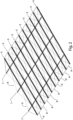
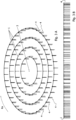
- the support structure for solar panels comprises a plurality of (and preferably two or more) concentric tracks or rails 1, with a circular geometry or with a polygonal geometry which can be approximated to a circular geometry, which are fixed to the ground or to a generic supporting surface through pilings 4, and a plurality of pylons 5, which are connected to related frames 14 supporting a plurality of solar panels 6 ( fig. 1 ).
- the pylons 5 are bound to the tracks or rails 1 and move on said tracks 1 through drive wheels 9; furthermore, the pylons 5 are connected together by means of perpendicular or vertical trusses 7, which form a braced frame 8 with said pylons 5 ( fig. 2 ).
- the whole movable structure formed by the pylons 5 and the trusses 7 rotates around a central bearing or node 3, which houses an electronic control unit 22, which controls the whole support structure and which is connected to the pylons 5 via a connecting frame 18 ( fig. 3A, 3B , 5 , 7, 8 ).
- the appended figure 1 shows a plan view of one embodiment of the support structure for solar panels according to the present invention, which comprises a fixed portion, constituted by four circular tracks 1 resting on the foundation pilings 4, and a movable portion, constituted by the metallic structures of the pylons 5, on which the frames 14 supporting the solar panels 6 are mounted, which rotate around the central bearing 3.
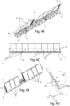
- the azimuthal rotation of the movable portion occurs through the drive wheels 9, which rest on the circular rails or tracks 1 and which are linked to the pylons 5 through suitable support means 13, while the zenithal rotation of the structure occurs around an hinge axis or pin 10, by means of suitable chain actuators 11, which move a particular eccentric kinematism 12 ( fig. 4A, 4B, 4C, 4D , 9A, 9B, 9C ).
- the whole movable portion formed by the pylons 5 rests, through the drive wheels 9, on the circular tracks or rails 1 and rotates around the central axis 15 of the bearing 3, where, through a four-way junction, it is possible to connect the pylons 5; therefore, the solar panels 6 rotate either according to an azimuthal direction (around the central bearing or node 3) and according to a zenithal direction (around the hinge axis or pin 10).
- An adjustment of the alignment between the rails 1 along a vertical plane is performed by means of a control system for controlling the height of said rails 1 over the foundation pilings 4, while an inverter 21 is installed in a symmetrical central position of each pylon 5; the electrical connecting cables run along the vertical trusses of the frame 18 to connect the central node 3, inside of which the electronic control unit 22 is installed.
- Figures 6A and 6B show the anti-shadowing function of the support structure according to the invention; without the anti-shadowing function ( fig. 6A ), the solar radiation 19 would be able to hit only the first pylon 5 of the solar panels 6, while the back pylons 5 would be only partially hit and would be covered by the shadow 20 generated from the first pylon 5, while the structure according to the invention allows rotating one or more frames 14 mounted on pylons 5 (which would generate the shadow 20) according to the opposite direction with respect to the zenithal direction, thus leaving the solar radiation 19 hits the whole surface of the solar panels 6, which are provided inside the frames 14 of the back pylons 5 ( fig. 6B ).
- the operation mode of the support structure for solar panels which is the object of the present invention, is substantially the following.
- the movable portions or structures rest on the rails 1 and said rails 1 constitute the path around which the pylons 5, which are able to support the frames 14 where the solar panels 6 are mounted, rotate; said rotation occurs by means of coated drive wheels 9, in order to realize the azimuthal tracking RA (from east to west) of the solar radiation 19.
- the movable structures described in the embodiment of the present invention are made of metal, however nothing prevents the use of different materials, such as buildings materials; furthermore, the movable structures are preferably placed at a certain height from the ground over a surface or area without shadowing.
- the solar panels (which are constituted by photovoltaic or thermal panels) are placed inside special frames 14, which are constituted of metal support means hinged to the carrying structure of the respective pylon 5, while suitable actuators (the inverters 11, 21) control the zenithal tracking RZ of all the panels 6 which are mounted on a respective pylon 5, so as to perform the tracking function of the solar radiation 19 and the solar radiation 19 is able to hit each panel 6 according to a direction which is perpendicular to the surface of the panel 6 (this is the condition according to which an optimum energy efficiency is performed).
- the frame 14 contains a plurality of solar panels 6, such as modular panels, and the actuators 11, 21 control the solar tracking by controlling the azimuthal rotation RA and the zenithal rotation RZ.
- the tracks or rails 1 constitute the fixed portion of the support structure which, according to the invention, behaves as a large bearing around which the whole movable portion of the structure rotates, by leaning on the rails 1 through the coated wheels 9; moreover, the wheels 9 can be constituted by simple support wheels for distributing the load and/or drive wheels.
- the electronic unit control 22 shall decrease the shading by rotating the frames 14 of the panels 6 in a direction opposite to the direction of the solar tracking, so as to obtain the least possible shading for solar panels 6 which are positioned immediately behind the panels 6 which directly receive the solar radiation 19.
- Suitable actuators 21 are provided for said rotation, so as to allow the zenithal tracking and to make angular rotations with angles greater than 90 °. Therefore, the azimuthal and zenithal rotations RA, RZ allows a complete tracking of the sun's trajectory throughout the day for any position of the tracker.
- the movements are then controlled for each single pylon 5 by the electronic control unit 22, which instantly controls the position of each panel 6 and keeps said position, so that the solar radiation 19, which hits the panel 6, is always perpendicular to the surface of the solar panel 6, in order to maximize the energy production, also limiting the shading of the other pylons 5.
- the electronic control unit 22 analyses the weather conditions, so as to move the pylons 5 supporting the panels 6 among positions in which a minimum resistance to the wind is provided, and is also able to control one or two types of drive wheels 9, which are independent of each other since the connection between the wheels 9 and the traction axis occurs through a free wheel; in particular, when a first type of wheel 9 is used for the azimuthal rotation throughout the day, according to the latitude of the place where the structure is installed, the other type of wheels 9 cannot be used, given the presence of the free wheel, while the other wheels 9 are always used for the azimuthal rotation, but shall perform the quick services of movement, such as the fast return of the structure for a new collimation, the maintenance of the structure and/or other needs, thus avoiding that the time during which the tracker returns to the starting position is equal to the tracking time (which is equal to about 8/10 hours).
- said different types of wheels turn at different speeds between them to facilitate the rebooting.
- the support structure according to the invention is able to maintain the tracking of a plurality of pylons 5 with frames 14 containing solar panels 6, in which case the yield is greater than 30-35% with respect to a fixed solar panel.
- the structure which has a uniform load distribution over the entire surface, can be mounted isolated outside, thus allowing cultivation below the structure, or can be installed on existing buildings with a flat layer (such as flat roofs or greenhouses), or it can be provided for covering a building, in order to considerably decrease with respect to the known structures, the environmental impact.
- the support structure also allows the maintenance of failure solar panels without blocking the operation of the other panels.
Landscapes
- Engineering & Computer Science (AREA)
- Physics & Mathematics (AREA)
- Life Sciences & Earth Sciences (AREA)
- Sustainable Development (AREA)
- Sustainable Energy (AREA)
- Thermal Sciences (AREA)
- Chemical & Material Sciences (AREA)
- Combustion & Propulsion (AREA)
- Mechanical Engineering (AREA)
- General Engineering & Computer Science (AREA)
- Photovoltaic Devices (AREA)
Claims (5)
- Structure porteuse pour panneaux solaires (6), comprenant au moins deux crémaillères ou rails concentriques (1) ayant une géométrie circulaire ou une géométrie polygonale qui peut être rapprochée d'une géométrie circulaire, qui sont fixés à une surface de support par l'intermédiaire de pieux de fondation (4), etplusieurs pylônes parallèles (5), articulés à des cadres connexes (14) contenant plusieurs panneaux solaires (6) et reliés entre eux au moyen de fermes perpendiculaires (7) qui forment un cadre contreventé (8) avec lesdits pylônes (5), lesdits pylônes (5) sont liés auxdites voies ou rails (1) et se déplacent sur lesdites voies ou rails (1) par l'intermédiaire de roues motrices (9) qui reposent sur lesdites voies ou rails (1) et qui sont reliées auxdits pylônes (5) par des moyens de support (13), de sorte que lesdits pylônes (5) et lesdites fermes (7) tournent autour d'un palier ou noeud central (3),une unité de commande électronique (22) logée dans le palier ou noeud central (3) et reliée aux pylônes (5) par l'intermédiaire d'un cadre de connexion (18), contrôlant ladite structure de support, lesdits panneaux solaires (6) sont ainsi libres de tourner dans l'espace selon une direction azimutale (RA) autour dudit palier ou noeud central (3) par l'intermédiaire desdites roues motrices (9) et libres de tourner dans l'espace selon une direction zénithale (RZ) autour d'un axe de charnière ou broche (10), qui est placé au centre et longitudinalement sur chaque cadre (14) contenant lesdits panneaux solaires (6),dans laquelle lesdits panneaux solaires (6) qui sont installés sur lesdits cadres connexes (14) de ladite pluralité de pylônes (5) sont tournés selon ladite direction zénithale (RZ) et dans la direction opposée par rapport aux panneaux solaires (6) qui sont installés sur les cadres (14) des pylônes adjacents (5) de ladite structure de support, lorsque le rayonnement solaire (19) est orienté à des angles inférieurs à 25° par rapport à l'horizon, afin que lesdits panneaux solaires (6) ne fassent pas d'ombre à d'autres panneaux solaires adjacents (6),et dans lequel ladite unité de commande électronique (22) analyse les conditions météorologiques, afin de déplacer les pylônes (5) supportant les panneaux (6) entre les positions dans lesquelles une résistance minimale au vent est fournie, et est également en mesure de contrôler lesdites roues motrices (9).
- Structure de support selon la revendication 1, caractérisée par le fait que les panneaux solaires (6) sont constitués de panneaux solaires modulaires (6).
- Structure de support selon au moins une des revendications précédentes, caractérisée par le fait que lesdits panneaux solaires (6) sont constitués de panneaux solaires et/ou de panneaux photovoltaïques et/ou de panneaux thermiques.
- Structure de support selon au moins l'une des revendications précédentes, caractérisée par le fait que les roues motrices (9) sont d'au moins deux types différents et indépendants entre eux, de sorte que lorsqu'un premier type de roues est utilisé pour une rotation azimutale de suivi, un second type de roues, qui est également utilisé pour ladite rotation azimutale, effectue un retour rapide de la structure pour une nouvelle collimation.
- Structure de support selon la revendication 4, caractérisée par le fait que les différents types de roues (9) tournent à des vitesses différentes.
Applications Claiming Priority (1)
| Application Number | Priority Date | Filing Date | Title |
|---|---|---|---|
| PCT/IT2014/000106 WO2015155792A1 (fr) | 2014-04-09 | 2014-04-09 | Structure de support pour panneaux solaires |
Publications (3)
| Publication Number | Publication Date |
|---|---|
| EP3129726A1 EP3129726A1 (fr) | 2017-02-15 |
| EP3129726B1 true EP3129726B1 (fr) | 2024-08-21 |
| EP3129726C0 EP3129726C0 (fr) | 2024-08-21 |
Family
ID=51211823
Family Applications (1)
| Application Number | Title | Priority Date | Filing Date |
|---|---|---|---|
| EP14741680.4A Active EP3129726B1 (fr) | 2014-04-09 | 2014-04-09 | Structure porteuse pour panneaux solaires |
Country Status (6)
| Country | Link |
|---|---|
| US (1) | US10168076B2 (fr) |
| EP (1) | EP3129726B1 (fr) |
| AU (1) | AU2014390715B2 (fr) |
| CA (1) | CA2945270A1 (fr) |
| WO (1) | WO2015155792A1 (fr) |
| ZA (1) | ZA201607575B (fr) |
Families Citing this family (3)
| Publication number | Priority date | Publication date | Assignee | Title |
|---|---|---|---|---|
| US9471050B2 (en) * | 2013-01-15 | 2016-10-18 | Wovn, Inc. | Solar tracker and related methods, devices, and systems |
| GR1009663B (el) | 2018-10-04 | 2019-12-05 | Γεωργιος Αχιλλεα Γκαμανης | Βελτιωμενος ηλιακος σταθμος παραγωγης |
| US12218623B1 (en) | 2024-07-19 | 2025-02-04 | DoubleLand LLC | Systems and methods for multi-position solar panel arrays |
Citations (3)
| Publication number | Priority date | Publication date | Assignee | Title |
|---|---|---|---|---|
| US20100212653A1 (en) * | 2009-02-25 | 2010-08-26 | Solfocus, Inc. | Field Level Tracker Controller |
| US20110023938A1 (en) * | 2007-07-13 | 2011-02-03 | Buchel Arthur R | Solar power plant |
| FR2973985A1 (fr) * | 2011-04-12 | 2012-10-19 | Nergy B | Dispositif d'arrosage pivotant heliotrope comportant une surface photovoltaïque |
Family Cites Families (24)
| Publication number | Priority date | Publication date | Assignee | Title |
|---|---|---|---|---|
| US7192146B2 (en) * | 2003-07-28 | 2007-03-20 | Energy Innovations, Inc. | Solar concentrator array with grouped adjustable elements |
| EP1698841A3 (fr) * | 2005-02-25 | 2007-04-18 | Matthias Unterholzner | Bâtiment industriel avec collecteurs solaires |
| ES2300222B1 (es) * | 2007-06-25 | 2009-08-06 | Mac-Puar Servicios Industriales, S.L. | Seguidor solar. |
| ES2301430B1 (es) * | 2007-10-08 | 2009-02-16 | Saima Taldea, S.L. | Seguidor solar accionado por un unico motor. |
| CN102027298B (zh) * | 2008-03-31 | 2012-11-28 | 皮雷利&C.有限公司 | 太阳跟踪设备 |
| US20090250095A1 (en) * | 2008-04-05 | 2009-10-08 | Brent Perry Thorley | Low-profile solar tracking module |
| ES2352767B1 (es) * | 2008-07-10 | 2011-09-28 | Ingenieria Y Aplicaciones Solares, .Sl | Seguidor solar circular de doble eje. |
| ES2366505B1 (es) * | 2008-07-16 | 2012-09-14 | Benito Martín Barbero | Seguidor solar de doble eje. |
| WO2010102256A2 (fr) * | 2009-03-05 | 2010-09-10 | Gedalia Vinokurov | Système de suivi pour panneaux solaires |
| WO2010141750A2 (fr) * | 2009-06-03 | 2010-12-09 | Gravitas Group Llc | Système de suivi du soleil à panneaux solaires et système de montage |
| GR1007242B (el) * | 2009-12-21 | 2011-04-20 | Κωνσταντινος Στεφανιδης | Περιστρεφομενη και ανακλινομενη εγκατασταση φωτοβολταϊκων στοιχειων |
| US20110168232A1 (en) * | 2010-01-14 | 2011-07-14 | Solaria Corporation | Method and System for Providing Tracking for Concentrated Solar Modules |
| US9170033B2 (en) * | 2010-01-20 | 2015-10-27 | Brightsource Industries (Israel) Ltd. | Method and apparatus for operating a solar energy system to account for cloud shading |
| US9285139B2 (en) * | 2010-01-28 | 2016-03-15 | Coolearth Solar | Structure and articulation system for solar collectors |
| US9404677B2 (en) * | 2010-05-17 | 2016-08-02 | Ric Enterprises | Inflatable linear heliostatic concentrating solar module |
| WO2012042888A1 (fr) * | 2010-10-01 | 2012-04-05 | Tokyo Institute Of Technology | Appareil de collecte de chaleur solaire du type linéaire croisé |
| JP5634369B2 (ja) * | 2011-09-27 | 2014-12-03 | 株式会社エルム | 太陽追尾型太陽光発電システム |
| US9471050B2 (en) * | 2013-01-15 | 2016-10-18 | Wovn, Inc. | Solar tracker and related methods, devices, and systems |
| CN105075108A (zh) * | 2013-04-04 | 2015-11-18 | 株式会社Elm | 太阳跟踪型太阳能发电系统 |
| US20160161151A1 (en) * | 2013-07-11 | 2016-06-09 | Solar Fire Concentration Oy | Method and arrangement for utilizing solar energy, method and system for implementing and designing an arrangement for utilizing solar energy and computer program product |
| US10006665B2 (en) * | 2014-06-27 | 2018-06-26 | Sunpower Corporation | Solar tracker drive |
| US9477065B1 (en) * | 2014-12-05 | 2016-10-25 | Edisun Microgrids, Inc. | Heliostat array |
| WO2018044796A1 (fr) * | 2016-08-29 | 2018-03-08 | SacTec Solar Inc. | Systèmes de panneaux solaires transportables à déploiement rapide et procédés d'utilisation desdits systèmes de panneaux solaires |
| US20180076757A1 (en) * | 2016-09-09 | 2018-03-15 | Edisun Microgrids, Inc. | Solar panel tracking assembly |
-
2014
- 2014-04-09 WO PCT/IT2014/000106 patent/WO2015155792A1/fr not_active Ceased
- 2014-04-09 CA CA2945270A patent/CA2945270A1/fr not_active Abandoned
- 2014-04-09 US US15/302,671 patent/US10168076B2/en active Active
- 2014-04-09 AU AU2014390715A patent/AU2014390715B2/en not_active Ceased
- 2014-04-09 EP EP14741680.4A patent/EP3129726B1/fr active Active
-
2016
- 2016-11-02 ZA ZA2016/07575A patent/ZA201607575B/en unknown
Patent Citations (3)
| Publication number | Priority date | Publication date | Assignee | Title |
|---|---|---|---|---|
| US20110023938A1 (en) * | 2007-07-13 | 2011-02-03 | Buchel Arthur R | Solar power plant |
| US20100212653A1 (en) * | 2009-02-25 | 2010-08-26 | Solfocus, Inc. | Field Level Tracker Controller |
| FR2973985A1 (fr) * | 2011-04-12 | 2012-10-19 | Nergy B | Dispositif d'arrosage pivotant heliotrope comportant une surface photovoltaïque |
Also Published As
| Publication number | Publication date |
|---|---|
| CA2945270A1 (fr) | 2015-10-15 |
| EP3129726C0 (fr) | 2024-08-21 |
| WO2015155792A1 (fr) | 2015-10-15 |
| US20170045267A1 (en) | 2017-02-16 |
| US10168076B2 (en) | 2019-01-01 |
| EP3129726A1 (fr) | 2017-02-15 |
| AU2014390715B2 (en) | 2019-12-19 |
| AU2014390715A1 (en) | 2016-11-24 |
| ZA201607575B (en) | 2020-02-26 |
Similar Documents
| Publication | Publication Date | Title |
|---|---|---|
| AU2007330684B2 (en) | Biaxial solar tracker | |
| US7705277B2 (en) | Sun tracking solar panels | |
| WO2012046134A1 (fr) | Appareil suiveur permettant de capter l'énergie solaire et mécanisme de déplacement d'axe relatif | |
| US8242424B2 (en) | Single axis solar tracker | |
| CA2727222A1 (fr) | Collecteurs solaires autodeployants montes sur cardans | |
| EP2163834A1 (fr) | Appareil de poursuite de rayonnement solaire pour des panneaux absorbant ce rayonnement solaire | |
| US20090025775A1 (en) | Dynamic solar tracking system | |
| DE102011103724A1 (de) | Vorrichtung zur Drehung einer Trägerstruktur um eine Hauptachse für den Einsatz in einer mit planaren Elementen oder Flächen ausgestatteten Anlage, insbesondere einer Solaranlage | |
| KR20210070094A (ko) | 2축 구동식 태양광 발전 시스템 | |
| DE202011103199U1 (de) | Vorrichtung zur Drehung einer Trägerstruktur um eine Hauptachse für den Einsatz in einer mit planaren Elementen oder Flächen ausgestatteten Anlage, insbesondere einer Solaranlage | |
| AU2014390715B2 (en) | Supporting structure for solar panels | |
| WO2013158496A1 (fr) | Nouvelle conception de suiveur solaire à deux axes pour déploiement à faible coût et profil pour moments de charge réduits | |
| KR20210070085A (ko) | 지주형 태양광 발전 시스템 | |
| DE202011105918U1 (de) | Vorrichtung zur Drehung einer Trägerstruktur um eine Hauptachse für den Einsatz in einer mit planaren Elementen oder Flächen ausgestatteten Anlage, insbesondere einer Solaranlage | |
| WO2013046999A1 (fr) | Système de production d'énergie solaire à poursuite du soleil | |
| US20240007044A1 (en) | Bifacial photovoltaic module, single axis solar tracker and operating method thereof | |
| EP4002685B1 (fr) | Tracker solaire a axe unique et son procede de fonctionnement | |
| US20200295701A1 (en) | Load-bearing structure for single-axis for tracking photovoltaic panels | |
| KR102079713B1 (ko) | 경작지용 풍력 및 태양광 하이브리드 발전장치 | |
| NZ725871A (en) | Supporting structure for solar panels | |
| EP3888241B1 (fr) | Appareil de suivi solaire | |
| BG113152A (bg) | Активно следяща система за разположение на соларни панели | |
| JPS60126857A (ja) | 光電パネル支持用構築体とその構築方法 | |
| DE202011103307U1 (de) | Vorrichtung zur Drehung einer Trägerstruktur um eine Hauptachse für den Einsatz in einer mit planaren Elementen oder Flachen ausgestalteten Anlage. insbesondere einer Solaranlage | |
| WO2025037293A1 (fr) | Dispositif modulaire de poursuite solaire à axe unique et système utilisant celui-ci |
Legal Events
| Date | Code | Title | Description |
|---|---|---|---|
| STAA | Information on the status of an ep patent application or granted ep patent |
Free format text: STATUS: THE INTERNATIONAL PUBLICATION HAS BEEN MADE |
|
| PUAI | Public reference made under article 153(3) epc to a published international application that has entered the european phase |
Free format text: ORIGINAL CODE: 0009012 |
|
| STAA | Information on the status of an ep patent application or granted ep patent |
Free format text: STATUS: REQUEST FOR EXAMINATION WAS MADE |
|
| 17P | Request for examination filed |
Effective date: 20161011 |
|
| AK | Designated contracting states |
Kind code of ref document: A1 Designated state(s): AL AT BE BG CH CY CZ DE DK EE ES FI FR GB GR HR HU IE IS IT LI LT LU LV MC MK MT NL NO PL PT RO RS SE SI SK SM TR |
|
| AX | Request for extension of the european patent |
Extension state: BA ME |
|
| DAX | Request for extension of the european patent (deleted) | ||
| STAA | Information on the status of an ep patent application or granted ep patent |
Free format text: STATUS: EXAMINATION IS IN PROGRESS |
|
| 17Q | First examination report despatched |
Effective date: 20200408 |
|
| P01 | Opt-out of the competence of the unified patent court (upc) registered |
Effective date: 20230601 |
|
| REG | Reference to a national code |
Ref country code: DE Ref legal event code: R079 Ipc: F24S0030452000 Ref country code: DE Ref legal event code: R079 Ref document number: 602014090725 Country of ref document: DE Free format text: PREVIOUS MAIN CLASS: F24J0002540000 Ipc: F24S0030452000 |
|
| GRAP | Despatch of communication of intention to grant a patent |
Free format text: ORIGINAL CODE: EPIDOSNIGR1 |
|
| STAA | Information on the status of an ep patent application or granted ep patent |
Free format text: STATUS: GRANT OF PATENT IS INTENDED |
|
| RIC1 | Information provided on ipc code assigned before grant |
Ipc: F24S 30/452 20180101AFI20240221BHEP |
|
| INTG | Intention to grant announced |
Effective date: 20240326 |
|
| GRAS | Grant fee paid |
Free format text: ORIGINAL CODE: EPIDOSNIGR3 |
|
| GRAA | (expected) grant |
Free format text: ORIGINAL CODE: 0009210 |
|
| STAA | Information on the status of an ep patent application or granted ep patent |
Free format text: STATUS: THE PATENT HAS BEEN GRANTED |
|
| AK | Designated contracting states |
Kind code of ref document: B1 Designated state(s): AL AT BE BG CH CY CZ DE DK EE ES FI FR GB GR HR HU IE IS IT LI LT LU LV MC MK MT NL NO PL PT RO RS SE SI SK SM TR |
|
| REG | Reference to a national code |
Ref country code: GB Ref legal event code: FG4D |
|
| REG | Reference to a national code |
Ref country code: CH Ref legal event code: EP |
|
| REG | Reference to a national code |
Ref country code: DE Ref legal event code: R096 Ref document number: 602014090725 Country of ref document: DE |
|
| REG | Reference to a national code |
Ref country code: IE Ref legal event code: FG4D |
|
| U01 | Request for unitary effect filed |
Effective date: 20240910 |
|
| U07 | Unitary effect registered |
Designated state(s): AT BE BG DE DK EE FI FR IT LT LU LV MT NL PT RO SE SI Effective date: 20240926 |
|
| P04 | Withdrawal of opt-out of the competence of the unified patent court (upc) registered |
Free format text: CASE NUMBER: APP_53097/2024 Effective date: 20240923 |
|
| P05 | Withdrawal of opt-out of the competence of the unified patent court (upc) changed |
Free format text: CASE NUMBER: APP_53097/2024 Effective date: 20240926 |
|
| PG25 | Lapsed in a contracting state [announced via postgrant information from national office to epo] |
Ref country code: NO Free format text: LAPSE BECAUSE OF FAILURE TO SUBMIT A TRANSLATION OF THE DESCRIPTION OR TO PAY THE FEE WITHIN THE PRESCRIBED TIME-LIMIT Effective date: 20241121 |
|
| PG25 | Lapsed in a contracting state [announced via postgrant information from national office to epo] |
Ref country code: PL Free format text: LAPSE BECAUSE OF FAILURE TO SUBMIT A TRANSLATION OF THE DESCRIPTION OR TO PAY THE FEE WITHIN THE PRESCRIBED TIME-LIMIT Effective date: 20240821 Ref country code: GR Free format text: LAPSE BECAUSE OF FAILURE TO SUBMIT A TRANSLATION OF THE DESCRIPTION OR TO PAY THE FEE WITHIN THE PRESCRIBED TIME-LIMIT Effective date: 20241122 |
|
| PG25 | Lapsed in a contracting state [announced via postgrant information from national office to epo] |
Ref country code: IS Free format text: LAPSE BECAUSE OF FAILURE TO SUBMIT A TRANSLATION OF THE DESCRIPTION OR TO PAY THE FEE WITHIN THE PRESCRIBED TIME-LIMIT Effective date: 20241221 |
|
| PG25 | Lapsed in a contracting state [announced via postgrant information from national office to epo] |
Ref country code: HR Free format text: LAPSE BECAUSE OF FAILURE TO SUBMIT A TRANSLATION OF THE DESCRIPTION OR TO PAY THE FEE WITHIN THE PRESCRIBED TIME-LIMIT Effective date: 20240821 |
|
| PG25 | Lapsed in a contracting state [announced via postgrant information from national office to epo] |
Ref country code: RS Free format text: LAPSE BECAUSE OF FAILURE TO SUBMIT A TRANSLATION OF THE DESCRIPTION OR TO PAY THE FEE WITHIN THE PRESCRIBED TIME-LIMIT Effective date: 20241121 Ref country code: ES Free format text: LAPSE BECAUSE OF FAILURE TO SUBMIT A TRANSLATION OF THE DESCRIPTION OR TO PAY THE FEE WITHIN THE PRESCRIBED TIME-LIMIT Effective date: 20240821 |
|
| PG25 | Lapsed in a contracting state [announced via postgrant information from national office to epo] |
Ref country code: RS Free format text: LAPSE BECAUSE OF FAILURE TO SUBMIT A TRANSLATION OF THE DESCRIPTION OR TO PAY THE FEE WITHIN THE PRESCRIBED TIME-LIMIT Effective date: 20241121 Ref country code: PL Free format text: LAPSE BECAUSE OF FAILURE TO SUBMIT A TRANSLATION OF THE DESCRIPTION OR TO PAY THE FEE WITHIN THE PRESCRIBED TIME-LIMIT Effective date: 20240821 Ref country code: NO Free format text: LAPSE BECAUSE OF FAILURE TO SUBMIT A TRANSLATION OF THE DESCRIPTION OR TO PAY THE FEE WITHIN THE PRESCRIBED TIME-LIMIT Effective date: 20241121 Ref country code: IS Free format text: LAPSE BECAUSE OF FAILURE TO SUBMIT A TRANSLATION OF THE DESCRIPTION OR TO PAY THE FEE WITHIN THE PRESCRIBED TIME-LIMIT Effective date: 20241221 Ref country code: HR Free format text: LAPSE BECAUSE OF FAILURE TO SUBMIT A TRANSLATION OF THE DESCRIPTION OR TO PAY THE FEE WITHIN THE PRESCRIBED TIME-LIMIT Effective date: 20240821 Ref country code: GR Free format text: LAPSE BECAUSE OF FAILURE TO SUBMIT A TRANSLATION OF THE DESCRIPTION OR TO PAY THE FEE WITHIN THE PRESCRIBED TIME-LIMIT Effective date: 20241122 Ref country code: ES Free format text: LAPSE BECAUSE OF FAILURE TO SUBMIT A TRANSLATION OF THE DESCRIPTION OR TO PAY THE FEE WITHIN THE PRESCRIBED TIME-LIMIT Effective date: 20240821 |
|
| PG25 | Lapsed in a contracting state [announced via postgrant information from national office to epo] |
Ref country code: SM Free format text: LAPSE BECAUSE OF FAILURE TO SUBMIT A TRANSLATION OF THE DESCRIPTION OR TO PAY THE FEE WITHIN THE PRESCRIBED TIME-LIMIT Effective date: 20240821 |
|
| PG25 | Lapsed in a contracting state [announced via postgrant information from national office to epo] |
Ref country code: CZ Free format text: LAPSE BECAUSE OF FAILURE TO SUBMIT A TRANSLATION OF THE DESCRIPTION OR TO PAY THE FEE WITHIN THE PRESCRIBED TIME-LIMIT Effective date: 20240821 |
|
| PG25 | Lapsed in a contracting state [announced via postgrant information from national office to epo] |
Ref country code: SK Free format text: LAPSE BECAUSE OF FAILURE TO SUBMIT A TRANSLATION OF THE DESCRIPTION OR TO PAY THE FEE WITHIN THE PRESCRIBED TIME-LIMIT Effective date: 20240821 |
|
| U20 | Renewal fee for the european patent with unitary effect paid |
Year of fee payment: 12 Effective date: 20250428 |
|
| PLBE | No opposition filed within time limit |
Free format text: ORIGINAL CODE: 0009261 |
|
| STAA | Information on the status of an ep patent application or granted ep patent |
Free format text: STATUS: NO OPPOSITION FILED WITHIN TIME LIMIT |
|
| 26N | No opposition filed |
Effective date: 20250522 |
|
| REG | Reference to a national code |
Ref country code: CH Ref legal event code: H13 Free format text: ST27 STATUS EVENT CODE: U-0-0-H10-H13 (AS PROVIDED BY THE NATIONAL OFFICE) Effective date: 20251125 |
|
| PG25 | Lapsed in a contracting state [announced via postgrant information from national office to epo] |
Ref country code: MC Free format text: LAPSE BECAUSE OF FAILURE TO SUBMIT A TRANSLATION OF THE DESCRIPTION OR TO PAY THE FEE WITHIN THE PRESCRIBED TIME-LIMIT Effective date: 20240821 |
|
| GBPC | Gb: european patent ceased through non-payment of renewal fee |
Effective date: 20250409 |
|
| PG25 | Lapsed in a contracting state [announced via postgrant information from national office to epo] |
Ref country code: GB Free format text: LAPSE BECAUSE OF NON-PAYMENT OF DUE FEES Effective date: 20250409 |
|
| PG25 | Lapsed in a contracting state [announced via postgrant information from national office to epo] |
Ref country code: CH Free format text: LAPSE BECAUSE OF NON-PAYMENT OF DUE FEES Effective date: 20250430 |
|
| U20 | Renewal fee for the european patent with unitary effect paid |
Year of fee payment: 13 Effective date: 20260218 |
|
| PG25 | Lapsed in a contracting state [announced via postgrant information from national office to epo] |
Ref country code: IE Free format text: LAPSE BECAUSE OF NON-PAYMENT OF DUE FEES Effective date: 20250409 |