EP3130013B1 - Vorrichtung zur energiegewinnung aus einer fluidströmung mit einer dünnen schicht aus piezoelektrischem material - Google Patents
Vorrichtung zur energiegewinnung aus einer fluidströmung mit einer dünnen schicht aus piezoelektrischem material Download PDFInfo
- Publication number
- EP3130013B1 EP3130013B1 EP15721860.3A EP15721860A EP3130013B1 EP 3130013 B1 EP3130013 B1 EP 3130013B1 EP 15721860 A EP15721860 A EP 15721860A EP 3130013 B1 EP3130013 B1 EP 3130013B1
- Authority
- EP
- European Patent Office
- Prior art keywords
- layer
- energy
- piezoelectric
- vortex
- harvesting
- Prior art date
- Legal status (The legal status is an assumption and is not a legal conclusion. Google has not performed a legal analysis and makes no representation as to the accuracy of the status listed.)
- Active
Links
Images

Classifications
-
- H—ELECTRICITY
- H02—GENERATION; CONVERSION OR DISTRIBUTION OF ELECTRIC POWER
- H02N—ELECTRIC MACHINES NOT OTHERWISE PROVIDED FOR
- H02N2/00—Electric machines in general using piezoelectric effect, electrostriction or magnetostriction
- H02N2/18—Electric machines in general using piezoelectric effect, electrostriction or magnetostriction producing electrical output from mechanical input, e.g. generators
- H02N2/185—Electric machines in general using piezoelectric effect, electrostriction or magnetostriction producing electrical output from mechanical input, e.g. generators using fluid streams
-
- H—ELECTRICITY
- H10—SEMICONDUCTOR DEVICES; ELECTRIC SOLID-STATE DEVICES NOT OTHERWISE PROVIDED FOR
- H10N—ELECTRIC SOLID-STATE DEVICES NOT OTHERWISE PROVIDED FOR
- H10N30/00—Piezoelectric or electrostrictive devices
- H10N30/30—Piezoelectric or electrostrictive devices with mechanical input and electrical output, e.g. functioning as generators or sensors
- H10N30/304—Beam type
- H10N30/306—Cantilevers
-
- H—ELECTRICITY
- H10—SEMICONDUCTOR DEVICES; ELECTRIC SOLID-STATE DEVICES NOT OTHERWISE PROVIDED FOR
- H10N—ELECTRIC SOLID-STATE DEVICES NOT OTHERWISE PROVIDED FOR
- H10N30/00—Piezoelectric or electrostrictive devices
- H10N30/704—Piezoelectric or electrostrictive devices based on piezoelectric or electrostrictive films or coatings
- H10N30/706—Piezoelectric or electrostrictive devices based on piezoelectric or electrostrictive films or coatings characterised by the underlying bases, e.g. substrates
- H10N30/708—Intermediate layers, e.g. barrier, adhesion or growth control buffer layers
-
- H—ELECTRICITY
- H10—SEMICONDUCTOR DEVICES; ELECTRIC SOLID-STATE DEVICES NOT OTHERWISE PROVIDED FOR
- H10N—ELECTRIC SOLID-STATE DEVICES NOT OTHERWISE PROVIDED FOR
- H10N30/00—Piezoelectric or electrostrictive devices
- H10N30/80—Constructional details
- H10N30/87—Electrodes or interconnections, e.g. leads or terminals
Definitions
- the present invention relates to a device for harvesting energy from a fluidic flow.
- the present invention regards a device including a thin film of piezoelectric material.
- the patent US 6,424,079 describes an energy-harvesting system, which comprises a flexible central layer, made of dielectric material, and a first layer and a second layer of piezoelectric material (polyvinylidene fluoride, PVDF).
- the energy-harvesting system forms a plurality of piezoelectric elements, electrically separated from one another, each of which is constituted by a pair of electrodes arranged on opposite sides of one between the first and second layers of piezoelectric material.
- the thickness of the central layer is comprised between 100 ⁇ m and 110 ⁇ m.
- each of the first and second layers of piezoelectric material has a thickness comprised between 100 ⁇ m and 110 ⁇ m.
- the energy-harvesting system described in the patent US 6,424,079 is particularly efficient in the case where it operates within a liquid, in which case it enables harvesting of appreciable amounts of energy.
- the high stiffness does not enable optimization of the amount of energy recovered.
- PVDF in order to exhibit a piezoelectric behaviour, PVDF must be subjected to a high tensile stress.
- a PVDF layer with piezoelectric behaviour may not have a thickness of less than about tens of micrometers; otherwise, there is the risk of failure.
- the aim of the present invention is thus to provide an energy-harvesting device that will overcome at least in part the drawbacks of the known art.
- an energy-harvesting device is provided as defined in the annexed claims.
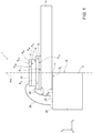
- Figure 1 shows an energy-harvesting device 1, which comprises: a supporting element 2 of a rigid type; a layer 4, referred to hereinafter as “flexible layer” 4; a first piezoelectric layer 6; a first conductive layer 8 and a second conductive layer 10; a layer referred to hereinafter as “base layer” or “interlayer” 12; and a bonding layer 14.
- the characteristics "flexible” and “rigid” of a given element are to be understood as referring to the capacity of this element to undergo dynamic deformation, or else not to undergo deformation, when the energy-harvesting device 1 is in use, i.e., when it is immersed, for example, in a flow of fluid having a rate of between 0.01m/s and 20m/s, as described hereinafter.
- the layer 4 is explicitly defined as flexible, also the first piezoelectric layer 6, the first and second conductive layers 8, 10, and the base layer 12 are flexible, i.e., deformable, and thus form a flexible structure together with the flexible layer 4.
- Figure 1 refers to an ideal condition of the energy-harvesting device 1 where the elements that make it up are not deformed, and thus the layers have substantially parallelepipedal shapes.
- this condition is not stable since, on account of the action of the weight and of the presence of residual stress within the energy-harvesting device 1, the latter undergoes deformation even in the absence of fluidic flow. Consequently, also in the presence of a laminar flow of fluid, the energy-harvesting device 1 induces turbulence in the fluidic flow, with consequent oscillation, among other things, of the flexible layer 4, since the aforementioned residual stress entails a force of elastic return that acts on the flexible layer 4 itself.
- the supporting element 2 is made, for example, of a material chosen from: stainless steel, glass, an epoxy resin, bakelite, or a plastic material. Furthermore, the supporting element 2 is delimited at the top by a surface S 2 , referred to hereinafter as "supporting surface” S 2 . In addition, the supporting element 2 is delimited laterally by an edge surface B, parallel to an axis y.
- the bonding layer 14 is made, for example, of a material chosen from: an epoxy resin, an adhesive with a silicone base or in any case a polymer base, an anodic gluing, or else a material designed to obtain bonding by covalent bonds activated by a plasma treatment.
- the bonding layer 14 extends over a portion of the supporting surface S 2 , with which it is in direct contact. Without any loss of generality, in the example illustrated in Figure 1 , the bonding layer 14 does not extend in cantilever fashion beyond the supporting element 2. In other words, the bonding layer 14 is delimited at the bottom by a respective surface, which is entirely in contact with the supporting surface S 2 .
- the flexible layer 4 is formed by a flexible material such as, for example, aluminium or a polymer chosen from among: Kapton, Mylar, polyethylene terephthalate (PET), or polyethylene naphthalate (PEN).
- the flexible layer 4 extends over the bonding layer 14, with which it is in direct contact.
- the flexible layer 4 is delimited at the top and at the bottom, respectively, by a first surface S 4a and a second surface S 4b , referred to hereinafter as "first and second flexible surfaces" S 4a , S 4b .
- the flexible layer 4 overlies, at a distance, the same portion of the supporting surface S 2 overlaid by the bonding layer 14. Further, the flexible layer 4 extends in cantilever fashion with respect to the assembly formed by the supporting element 2 and by the bonding layer 14. The flexible layer 4 is thus laterally staggered with respect to the supporting element 2.
- the flexible layer 4 extends in a direction x, which is orthogonal to the aforementioned axis y, stacked along which are, among other things, the supporting element 2, the gluing layer 14, and the flexible layer 4 itself.
- x which is orthogonal to the aforementioned axis y
- y which is orthogonal to the aforementioned axis y
- z likewise illustrated in Figure 1 is an axis z of an orthogonal reference system x, y, z.
- the base layer 12 is made, for example, of a material (referred to hereinafter as "base material") chosen from: aluminium nitride (AlN), silicon dioxide (SiO 2 ), titanium nitride (TiN), or tantalum (Ta).
- This base material has a columnar polycrystalline structure.
- the base layer 12 extends over the flexible layer 4, with which it is in direct contact, and is delimited at the top and at the bottom, respectively, by a first surface S 12a and a second surface S 12b , referred to hereinafter as "first and second base surfaces" S 12a , S 12b .
- the first and second base surfaces S 12a , S 12b have a same rectangular shape in top plan view and are aligned along the axis y, without any loss of generality.
- the second base surface S 12b is in contact with a portion of the first flexible surface S 4a , said portion overlying in part, at a distance, a peripheral portion of the supporting element 2.
- a first (non-entire) portion of the second base surface S 12b overlies, at a distance, the aforementioned peripheral portion of the supporting element 2, whereas a second portion of the second base surface S 12b extends, in top plan view, outside the supporting element 2, but in any case within the first flexible surface S 4a . Consequently, in top plan view, the edge surface B is overlaid by the second base surface S 12b .
- the first conductive layer 8 functions as first electrode and is arranged over the base layer 12, in direct contact with the first base surface S 12a .
- the first conductive layer 8 has, in top plan view, the same shape as the base layer 12, with which it is aligned along the axis y.
- the first conductive layer 8 may be made, for example, of a first conductive material chosen from among: molybdenum, aluminium, platinum, gold, tungsten, titanium, ruthenium, graphene, or else a copper and aluminium alloy.
- the first piezoelectric layer 6 is made of a first piezoelectric material, such as, for example, aluminium nitride (AlN) or a ternary compound of the latter, such as, for example, an alloy chosen from: ScAlN, YAlN, InAlN, CuAlN, CrAlN, or SmAlN.
- the first piezoelectric material may likewise be chosen from: ZnO, PZT (also known as lead zirconate titanate), LiNbO 3 LiTaO 3 and perovskites (CaTiO 3 , BaTiO 3 , etc.).
- the first piezoelectric layer 6 is formed by a thin film, arranged over the first conductive layer 8, in direct contact with the latter. Furthermore, the first piezoelectric layer 6 is delimited at the top and at the bottom, respectively, by a first and surface S 6a a second surface S 6b , referred to hereinafter as "first and second piezoelectric surfaces" S 6a , S 6b .
- the first and second piezoelectric surfaces S 6a , S 6b have, in top plan view, the same rectangular shape and are vertically aligned along the axis y. Furthermore, the second piezoelectric surface S 6b is entirely in contact with the first conductive layer 8, which is in turn delimited at the top and at the bottom respectively by a first surface S 8a and a second surface S 8b , referred to hereinafter as "first and second conductive surfaces" S 8a , S 8b .
- the first piezoelectric surface S 6a (and thus also the second piezoelectric surface S 6b ) has an area smaller than the area of the first conductive surface S 8a (and thus also of the second conductive surface S 8b ), which in turn, as mentioned previously, has an area smaller than the area of the first flexible surface S 4a .
- each of the first and second piezoelectric surfaces S 6a , S 6b is set to overlie the edge surface B of the supporting element 2. Consequently, the first piezoelectric layer 6 comprises a first portion, which overlies, at a distance, the aforementioned peripheral portion of the supporting element 2, and a second portion, which, in top plan view, is located externally with respect to the supporting element 2.
- both the first portion and the second portion of the first piezoelectric layer 6 fall within the first conductive surface S 8a , and thus also within the first flexible surface S 4a .
- the first piezoelectric layer 6 extends in cantilever fashion with respect to the supporting element 2.
- the second conductive layer 10 extends over the first piezoelectric layer 6, with which it is in direct contact.
- the second conductive layer 10 may be made of a second conductive material chosen from: molybdenum, aluminium, platinum, gold, tungsten, titanium, ruthenium, graphene, or else a copper and aluminium alloy.
- the second conductive layer 10 is delimited at the top and at the bottom respectively by a third conductive surface S 10a and a fourth conductive surface S 10b .
- the third and fourth conductive surfaces S 10a , S 10b have the same shape and are aligned along the axis y.
- each of the third and fourth conductive surfaces S 10a , S 10b has the same shape as the first and second piezoelectric surfaces S 6a , S 6b , with which it is aligned along the axis y.
- the edge surface B defines a plane of symmetry PH for the assembly formed, not only by the first piezoelectric layer 6, but also by the base layer 12 and the first and second conductive layers 8, 10.
- the plane of symmetry PH divides this assembly into two equal specular parts.
- the geometrical centres of the first and second piezoelectric surfaces S 6a , S 6b are thus coplanar with the edge surface B.
- the plane of symmetry PH is directed parallel to the axis y and perpendicular to the first piezoelectric layer 6, which overlies the edge that connects the edge surface B with the supporting surface S 2 .
- the edge surface B is transverse, but not perpendicular, with respect to the first piezoelectric layer 6.
- the energy-harvesting device 1 further comprises a first pad 20 and a second pad 22, made of conductive material, which extend on the supporting surface S 2 , laterally staggered with respect to the bonding layer 14 and to the flexible layer 4.
- the first and second pads 20, 22 are electrically connected, respectively, to the first and second conductive layers 8, 10 by a first wire bonding 24 and a second wire bonding 26, respectively.
- the first and second pads 20, 22 may be connected in a per se known manner to an external device (not illustrated) for supplying the latter with the electric power obtained, as described hereinafter, from the energy-harvesting device 1.
- the supporting element 2 has a thickness (measured along the axis y) comprised, for example, between 1mm and 5mm
- the bonding layer 14 has a thickness comprised, for example, between 50nm and 100nm
- the flexible layer 4 has a thickness comprised, for example, between 5 ⁇ m and 50 ⁇ m
- the base layer 12 has a thickness comprised, for example, between 15nm and 500nm
- the first conductive layer 8 has a thickness comprised, for example, between 5nm and 500nm
- the first piezoelectric layer 6 has a thickness comprised, for example, between 300nm and 3 ⁇ m, preferably between 300nm and 1.4 ⁇ m
- the second conductive layer 10 has a thickness comprised, for example, between 5nm and 1 ⁇ m.
- the first piezoelectric layer 6 has a dimension along the axis z smaller than the dimensions along the axis z of the supporting element 2 and of the flexible layer 4. Furthermore, in ideal conditions of non-deformation, the projection of the edge surface B parallel to the axis y divides the first piezoelectric layer 6 so that a first half of the latter overlies, at a distance, the supporting element 2, whereas a second half extends (in top plan view) outside the perimeter of the supporting element 2. Furthermore, it is assumed that the ratio between the area of either between the first and second piezoelectric surfaces S 6a , S 6b and the first flexible surface S 4a is less than 0.95. Lower values of this ratio bestow a greater flexibility on the energy-harvesting device 1.
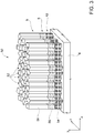
- the materials of the base layer 12, of the first piezoelectric layer 6, and of the first conductive layer 8 are such that they form a columnar structure 50 of a polycrystalline type, which comprises a plurality of columnar portions 52, as illustrated in Figure 3 .
- Each columnar portion 52 extends substantially parallel to the axis y and includes a first sub-portion 54, a second sub-portion 56, and a third sub-portion 58, which are stacked on top of one another and form, respectively, the base layer 12, the first conductive layer 8, and the first piezoelectric layer 6. Consequently, the first, second, and third sub-portions 54, 56, 58 are made, respectively, of the aforementioned base material, the first conductive material, and the first piezoelectric material.
- each one of the first, second, and third sub-portions 54, 56, 58 is formed by a corresponding grain (also known as "crystallite”); i.e., it is monocrystalline.
- the base material, the first conductive material, and the first piezoelectric material, and in particular the corresponding crystalline phases and the corresponding crystallographic orientations are such that, to a first approximation, at the interface between the first sub-portion 54 and the second sub-portion 56 and at the interface between the second sub-portion 56 and the third sub-portion 58 no dislocation arises; i.e., there occurs a local epitaxy.
- the interface between the first and second sub-portions 54, 56 and the interface between the second and third sub-portions 56, 58 are substantially without lattice defects.
- the corresponding grains of the first, second, and third sub-portions 54, 56, 58 are grown on top of one another in crystalline form on a single grain, i.e., for forming a sort of single global grain.
- Each columnar portion 52 is thus of a so-called pseudomorphic (or coherent) type; i.e., it is formed by portions of layers that, albeit having different lattice parameters, mate with one another in the plane of growth, parallel to the plane x, z.
- the second sub-portion 56 adapts, in the plane of growth, to the lattice parameter of the first sub-portion 54 by tensile or compressive deformation; likewise, the third sub-portion 58 adapts, in the plane of growth, to the lattice parameter of the second sub-portion 56 by tensile or compressive deformation.
- first, second, and third sub-portions 54, 56, 58 of each columnar portion 52 of the example illustrated in Figure 3 are formed respectively, from a crystallographic standpoint, by:
- the columnar portions 52 may join up to one another, for example, on account of the presence of chemical bonds that are set up between corresponding sub-portions of adjacent columnar portions.
- the columnar structure 50 bestows on the energy-harvesting device 1 a high strength, notwithstanding the extremely small thickness. Furthermore, the columnar structure 50 may be obtained, for instance, by growing the first conductive layer 8 using low-pressure sputtering (e.g., with pressures lower than 0.005 mbar) with low roughness (e.g., having a mean square value of less than 5nm) and with a compressive stress lower than - 0.5GPa.
- low-pressure sputtering e.g., with pressures lower than 0.005 mbar
- low roughness e.g., having a mean square value of less than 5nm
- the first piezoelectric layer 6 forms a sort of active region.
- the energy-harvesting device 1, and in particular the flexible layer 4 are put in oscillation by a fluidic flow, which may not necessarily be turbulent, the first piezoelectric layer 6 undergoes mechanical stress, along the so-called axis 1 (in the present case, parallel to the axis x). This stress is particularly high also on account of the geometrical arrangement of the first piezoelectric layer 6 with respect to the edge surface B.
- the biasing axis i.e., the axis along which there occurs separation of charge due to the piezoelectric effect
- the biasing axis is parallel to the axis y, this axis corresponding, if for example reference is made to the case where the first piezoelectric material is AlN or ZnO, to the so-called c-axis of the so-called unit cell.
- the charge displacement may be measured as an open-circuit voltage, or else as a short-circuit current, between the first and second pads 20, 22.
- the base layer 12 functions as tensile buffer, which guarantees the energy-harvesting device 1 a high resistance to deformation. Consequently, the first piezoelectric layer 6 may have a particularly small thickness, which, in turn, leads to the possibility of operating the energy-harvesting device 1 even with just a weak gas flow.
- a number of energy-harvesting devices 1 may form an energy-harvesting system 60.
- each energy-harvesting device 1 may be considered, from an electrical standpoint, as a bipole, the energy-harvesting devices 1 may be connected together in series or in parallel (the electrical connections are not illustrated).
- each energy-harvesting device 1 includes its own flexible layer 4.
- the energy-harvesting system has a single flexible layer, which is shared between a number of energy-harvesting devices 1; i.e., it has a number of active regions.
- the energy-harvesting devices that share the flexible layer supply voltages/currents that are in phase with one another.
- each one of the first and second piezoelectric surfaces S 6a , S 6b may have a shape without vertices.
- the first and second piezoelectric surfaces S 6a , S 6b may have the shape of a rectangle with rounded vertices.
- the first and second piezoelectric surfaces S 6a , S 6b have the shape of a polygon with rounded vertices, or else that of a circle or an ellipse. The presence of rounded vertices bestows a greater strength on the first piezoelectric layer 6, since it reduces the likelihood of cracks forming within the latter.
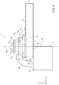
- the energy-harvesting device 1 may comprise a second piezoelectric layer 66, arranged over the second conductive layer 10, with which it is in direct contact, and made of a second piezoelectric material, which is for example the same as the first piezoelectric material.
- the energy-harvesting device 1 further comprises a third conductive layer 70, arranged over the second piezoelectric layer 66, with which it is in direct contact.
- the first wire bonding 24 connects, to the first pad 20, both the first conductive layer 8 and the third conductive layer 70 (the latter connection not being illustrated in Figure 5 ), which are then set, in use, at a same potential. Since, in use, also the second piezoelectric layer 66 undergoes deformation, it is possible to increase energy harvesting by the energy-harvesting device 1.
- the energy-harvesting device 1 may further comprise a coating layer 72 (illustrated in Figure 5 ), formed by dielectric material, such as, for example, parylene.
- the coating layer 72 functions as passivation layer and coats the exposed portions of the flexible layer 4, of the base layer 12, of the first conductive layer 6, of the first piezoelectric layer 6, of the second conductive layer 10, and, if present, of the second piezoelectric layer 66 and of the third conductive layer 70.
- the coating layer 72 coats the first and second pads 20, 22, as well as the first and second wire bondings 24, 26, even though the latter characteristic is not illustrated in Figure 5 , for reasons of clarity.
- the coating layer 72 coats the exposed portions of the supporting element 2.
- the coating layer 72 electrically insulates the energy-harvesting device 1, but for a first terminal and a second terminal (not illustrated), which are electrically connected to the first and second pads 20, 22, respectively, and are designed to be electrically connected to the outside world. Furthermore, the coating layer 72 bestows further strength on the energy-harvesting device 1 and functions as barrier in regard, for example, to water, oxygen and, more in general, any possible chemical agents.
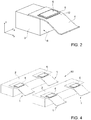
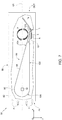
- FIGS 6 and 7 show a further example of the energy-harvesting system 60, which, without any loss of generality, includes just one energy-harvesting device 1. Furthermore, according to this embodiment, the energy-harvesting system 60 comprises a container 80, which has a tubular shape and houses the energy-harvesting device 1.
- the container 80 has, for example, a hollow parallelepipedal shape, and thus comprises four side walls 82, but is without the two bases, so that it defines an inlet opening IN and an outlet opening OUT, which may be traversed, in use, by the fluidic flow (represented by the arrows F).
- the container 80 may then channel the fluidic flow onto the energy-harvesting device 1.
- the orientation of the container 80 with respect to the direction of the fluidic flow may be varied, by using an actuator (not illustrated), so that the direction of the fluidic flow is parallel to the longitudinal axis LH of the container 80.
- an actuator not illustrated
- the energy-harvesting system 60 further comprises a vortex-generating element 90 of a rigid type, which, without any loss of generality, is constrained to the container 80 by a connecting rod 92, which is in turn fixed with respect to the container 80.
- a connecting rod 92 which is in turn fixed with respect to the container 80.
- the connecting rod 92 is constrained to the container 80, but may turn about its own longitudinal axis, or else in which the connecting rod 92 is fixed with respect to the container 80, but the vortex-generating element 90 may turn about the longitudinal axis of the connecting rod 92, in which case the vortex-generating element 90 orients itself according to the fluidic flow.
- the vortex-generating element 90 comprises a portion 94 shaped like a prism with a triangular base (with its height orthogonal to the longitudinal axis LH) and a cylindrical portion 96 made of a single piece. Consequently, the vortex-generating element 90 is delimited by a first plane wall 102 and a second plane wall 104, which are inclined by an angle ⁇ with respect to one another, and by a connecting wall 106, which connects the first and second plane walls 102, 104 and has a curved shape. Furthermore, the first and second plane walls 102, 104 contact one another along a line of contact 110, which forms an edge of the vortex-generating element 90 and is arranged orthogonal to the longitudinal axis LH of the container 80.
- the energy-harvesting device 1 is mechanically coupled to the vortex-generating element 90.
- the energy-harvesting device 1 is without the supporting element 2 since the vortex-generating element 90 itself functions as support. Consequently, the flexible layer 4 is constrained, at one of its ends, to the first plane wall 102. It follows that, in ideal conditions of non-deformation, the flexible layer 4 and the first piezoelectric layer 6 extend parallel to the first plane wall 102, the flexible layer 4 being set between the first plane wall 102 and the first piezoelectric layer 6.
- the first piezoelectric layer 6 is coupled to the vortex-generating element 90 so that, without any loss of generality, an imaginary plane passing through the line of contact 110 and perpendicular to the first plane wall 102 divides (in ideal conditions of non-deformation) the first piezoelectric layer 6 into two equal portions, arranged specular to one another with respect to the aforesaid imaginary plane. Furthermore, as is evident from Figure 7 , a first one between these two portions of the first piezoelectric layer 6 extends on one side with respect to the imaginary plane, together with the first plane wall 102, whereas the second portion extends on the other side.
- the first portion of the first piezoelectric layer 6 is aligned along the axis y with respect to a corresponding portion of the first plane wall 102 whereas the second portion extends beyond the imaginary plane, on the opposite side with respect to the first plane wall 102.
- the first portion of the first piezoelectric layer 6 overlies, at a distance, the corresponding portion of the first plane wall 102, whereas the second portion of the first piezoelectric layer 6 extends in cantilever fashion with respect to the first plane wall 102.
- a vortex V is formed in the proximity of the line of contact 110.
- the vortex V is formed, with respect to the first plane wall 102, on the side opposite to the side on which the first piezoelectric layer 6 is located.
- the vortex V is generated for interacting mechanically with the flexible layer 4 in order to cause a dynamic deformation of the flexible layer 4.
- the flexible layer 4 has a portion that extends in cantilever fashion from the first plane wall 102, the presence of the vortex V entails curving of this portion, which tends to approach the vortex V. This entails, among other things, deformation of the first piezoelectric layer 6.
- a number of energy-harvesting devices 1 are present, each of which is mechanically coupled to a corresponding vortex-generating element.
- the energy-harvesting devices 1 may be electrically connected together in series or in parallel.
- the vortex-generating elements, and thus the energy-harvesting devices 1, may all be coupled to the connecting rod 92, on top one another.
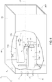
- embodiments of the invention comprise a first energy-harvesting device and a second energy-harvesting device, designated by 111a and 111b, respectively, which are arranged within the container 80, are the same as one another, and are coupled, respectively, to a first vortex-generating element and a second vortex-generating element, designated by 91a, 91b, respectively, which are the same as one another.
- the first and second vortex-generating elements 91a, 91b are arranged so that the respective first plane walls (designated, respectively, by 112a and 112b) are parallel to one another and aligned along the axis y. Further, the first and second vortex-generating elements 91a, 91b are oriented to be arranged specularly with respect to an axis parallel to the longitudinal axis LH of the container 80.
- the second plane walls of the first and second vortex-generating elements 91a, 91b are arranged crosswise with respect to one another and are arranged between the first plane wall 112a of the first vortex-generating element 91a and the first plane wall 112b of the second vortex-generating element 91b. Furthermore, the first and second energy-harvesting devices 111a, 111b are coupled to the first and second vortex-generating elements 91a, 91b so that they also are arranged specularly with respect to the longitudinal axis LH of the container 80.
- the first and second vortex-generating elements 91a, 91b cause formation of a pair of vortices V. It consequently happens that the flexible layers 4 of the first and second energy-harvesting devices 111a, 111b bend towards the longitudinal axis LH of the container 80, causing deformation of the corresponding first piezoelectric layers 6. The subsequent recession of the vortices V from the respective places where they are generated entails release of the first piezoelectric layers 6. Consequently, in use, the first and second energy-harvesting devices 111a and 111b supply, respectively, a first a.c. voltage and a second a.c.
- first and second energy-harvesting devices 111a and 111b are such that, when they oscillate, they do not impact against the walls of the container 80 and thus do not get damaged.
- the present energy-harvesting device enables generation of appreciable voltages even starting from a gaseous flow. For instance, assuming having available an embodiment with an overall thickness (excluding the supporting element) of approximately 26.5 ⁇ m, and in which the flexible layer 4 has a thickness of 25 ⁇ m, and assuming operation in a gaseous flow at a rate of 1.5m/s, it is possible to obtain a voltage of approximately 170mV, i.e., a voltage higher than what may be obtained with known systems based upon the use of PVDF layers of comparable thickness.
- the present energy-harvesting device does not envisage any constraint regarding the operating frequency since it does not avail itself of any element that must necessarily operate at a corresponding resonance frequency.
- the deformation of the active region is substantially independent of the frequency of oscillation of the flexible layer 4.
- the present energy-harvesting device is particularly quiet in operation.
- the present energy-harvesting device is suited to forming modular systems having, for example, three-dimensional configurations, i.e., three-dimensional distributions in space of the active regions. Furthermore, the present energy-harvesting device may be used for measuring the rate of the fluidic flow on the basis of energy harvesting.
- the relative arrangement of two or more elements of the present energy-harvesting device may be different from what has been described.
- the position of the first piezoelectric layer with respect to the supporting element, or else to the flexible layer may be different from what has been described.
- the supporting element itself may be absent, or in any case may have a different shape from what has been described, in which case the flexible layer is appropriately constrained to it in a per se known manner.
- the edge surface may have a different shape and may, for example, be at least partially curved, or in any case may be inclined in a different way.
- the supporting element defines an edge such that, given an imaginary plane that contains the edge and is perpendicular to the first piezoelectric layer, this imaginary plane divides the first piezoelectric layer into two portions, which, in ideal conditions of non-deformation, are preferably equal and arranged specularly.
- connections between the first and second pads 20, 22 and, respectively, the first and second conductive layers 8, 10 may be of a type different from what has been described.
- they may be formed by conductive paths that extend on the coating layer 72 and are in electrical contact with the first and second conductive layers 8, 10 and with the first and second pads 20, 22 thanks to so-called "conductive vias".
- first, second, and third conductive layers 8, 10, 70 may be electrically connected in a different way.
- first wire bonding 24 may connect the first pad 20 to the first conductive layer 8
- second wire bonding 26 may connect the second pad 22 to the third conductive layer 70, in which case the second conductive layer 10 may be floating.
- the base layer, the first conductive layer, the first and (if present) second piezoelectric layers, and the second and (if present) third conductive layers to have shapes different from what has been illustrated and described herein.
- the base material may be different from the first piezoelectric material.
Landscapes
- General Electrical Machinery Utilizing Piezoelectricity, Electrostriction Or Magnetostriction (AREA)
- Micromachines (AREA)
Claims (10)
- System, umfassend eine erste Vorrichtung (111a) zur Energiegewinnung aus einer Fluidströmung, wobei die erste Energiegewinnungsvorrichtung (111a) eine flexible Struktur (4, 6, 8, 10, 12, 66, 70) umfasst, die Folgendes aufweist:- eine Basisschicht (12);- eine erste leitfähige Schicht (8), die aus einem ersten leitfähigen Material gefertigt und oben auf der Basisschicht (12) angeordnet ist; und- eine erste piezoelektrische Schicht (6), die aus einem ersten piezoelektrischen Material gefertigt und oben auf der ersten leitfähigen Schicht (8) angeordnet ist;und wobei die Basisschicht (12), die erste leitfähige Schicht (8) und die erste piezoelektrische Schicht (6) eine kristalline Struktur (50) bilden, die eine Vielzahl pseudomorpher Abschnitte (52) aufweist; wobei die erste Energiegewinnungsvorrichtung (1) ferner eine flexible Schicht (4) umfasst, die so eingerichtet ist, dass sie von der Fluidströmung in Schwingungen versetzt wird, wobei die Basisschicht (12) oben auf der flexiblen Schicht (4) angeordnet ist;
wobei das System ferner ein erstes Wirbelerzeugungselement (91a) umfasst, das mechanisch mit der ersten Energiegewinnungsvorrichtung (111a) verbunden und so eingerichtet ist, dass es in Gegenwart der Fluidströmung einen Wirbel erzeugt, der mit zumindest einem Teil der flexiblen Schicht (4) in Wechselbeziehung steht; wobei das System ferner eine zweite Energiegewinnungsvorrichtung (111b) und ein zweites Wirbelerzeugungselement (91b) umfasst, das mechanisch mit der zweiten Energiegewinnungsvorrichtung (111b) verbunden ist, wobei das erste und zweite Wirbelerzeugungselement (91a, 91b) bezogen auf eine Achse (LH) spiegelbildlich angeordnet sind, wobei die erste und zweite Energiegewinnungsvorrichtung (111a, 111b) bezogen auf die Achse (LH) spiegelbildlich angeordnet sind;
wobei das System dadurch gekennzeichnet ist, dass von dem ersten und zweiten Wirbelerzeugungselement (91a, 91b) jedes teilweise durch einen jeweiligen ersten Seitenwandabschnitt (112a) und durch einen jeweiligen zweiten Seitenwandabschnitt (114a) begrenzt ist, die bezogen aufeinander geneigt sind und so verbunden sind, dass sie eine Kante (110) bilden, die bezogen auf die Achse (LH) rechtwinklig angeordnet ist, wobei der jeweilige erste Seitenwandabschnitt (112a) parallel zur Achse (LH) verläuft; und wobei die flexiblen Schichten (4) der ersten und zweiten Energiegewinnungsvorrichtung (111a, 111b) an dem ersten Seitenwandabschnitt (112a) des ersten Wirbelerzeugungselements (91a) beziehungsweise an dem ersten Seitenwandabschnitt (112b) des zweiten Wirbelerzeugungselements (91b) befestigt sind. - System nach Anspruch 1, wobei jeder pseudomorphe Abschnitt (52) eine Säulenform aufweist und eine erste Grenzfläche und eine zweite Grenzfläche aufweist.
- System nach Anspruch 1 oder Anspruch 2, wobei die erste piezoelektrische Schicht (6) eine Stärke zwischen 300 nm und 1,4 µm aufweist.
- System nach einem der vorhergehenden Ansprüche, wobei die erste piezoelektrische Schicht (6) eine erste Hauptfläche (S6a) bildet, die in der Draufsicht eine Form ohne Spitzen aufweist.
- System nach einem der vorhergehenden Ansprüche, wobei die Basisschicht (12) eine Stärke zwischen 15 nm und 500 nm aufweist.
- System nach einem der vorhergehenden Ansprüche, wobei die erste Energiegewinnungsvorrichtung (111a) ferner Folgendes umfasst: eine zweite leitfähige Schicht (10), die oben auf der ersten piezoelektrischen Schicht (6) angeordnet ist, eine zweite piezoelektrische Schicht (66), die oben auf der zweiten leitfähigen Schicht (10) angeordnet ist, und eine dritte leitfähige Schicht (70), die oben auf der zweiten piezoelektrischen Schicht (66) angeordnet ist.
- System nach Anspruch 1, wobei die flexible Schicht (4) aus einem Polymerwerkstoff gefertigt ist.
- System nach Anspruch 1 oder Anspruch 7, wobei die flexible Schicht (4) eine Stärke zwischen 5 µm und 50 µm aufweist.
- System nach einem der Ansprüche 1 bis 9, ferner umfassend ein steifes Stützelement (2), wobei ein Abschnitt der flexiblen Schicht (4) an dem steifen Stützelement (2) befestigt ist; und wobei die erste piezoelektrische Schicht (6) bezogen auf das steife Stützelement (2) auskragend verläuft.
- System nach Anspruch 1, ferner umfassend einen Behälter (80), wobei die erste Energiegewinnungsvorrichtung (1) und das erste Wirbelerzeugungselement (90) innerhalb des Behälters (80) angeordnet sind, der so eingerichtet ist, dass er die Fluidströmung aufnimmt und die Fluidströmung auf das erste Wirbelerzeugungselement (90; 91a) lenkt.
Applications Claiming Priority (2)
| Application Number | Priority Date | Filing Date | Title |
|---|---|---|---|
| ITTO20140313 | 2014-04-11 | ||
| PCT/IB2015/052626 WO2015155746A1 (en) | 2014-04-11 | 2015-04-10 | Device for harvesting energy from a fluidic flow including a thin film of piezoelectric material |
Publications (2)
| Publication Number | Publication Date |
|---|---|
| EP3130013A1 EP3130013A1 (de) | 2017-02-15 |
| EP3130013B1 true EP3130013B1 (de) | 2018-03-14 |
Family
ID=50943489
Family Applications (1)
| Application Number | Title | Priority Date | Filing Date |
|---|---|---|---|
| EP15721860.3A Active EP3130013B1 (de) | 2014-04-11 | 2015-04-10 | Vorrichtung zur energiegewinnung aus einer fluidströmung mit einer dünnen schicht aus piezoelektrischem material |
Country Status (3)
| Country | Link |
|---|---|
| US (1) | US10153713B2 (de) |
| EP (1) | EP3130013B1 (de) |
| WO (1) | WO2015155746A1 (de) |
Families Citing this family (21)
| Publication number | Priority date | Publication date | Assignee | Title |
|---|---|---|---|---|
| US11316447B2 (en) * | 2016-03-25 | 2022-04-26 | California Institute Of Technology | Flow energy harvesting devices and systems |
| US10367434B2 (en) | 2017-05-30 | 2019-07-30 | Saudi Arabian Oil Company | Harvesting energy from fluid flow |
| US11107630B2 (en) * | 2018-09-26 | 2021-08-31 | Taiwan Semiconductor Manufacturing Company, Ltd. | Integration scheme for breakdown voltage enhancement of a piezoelectric metal-insulator-metal device |
| KR20200099277A (ko) * | 2019-02-14 | 2020-08-24 | 국방과학연구소 | 퍼넬형 수중 에너지 하베스팅 장치 |
| KR20220034894A (ko) | 2019-07-19 | 2022-03-18 | 에바텍 아크티엔게젤샤프트 | 압전 코팅 및 증착 공정 |
| US11187044B2 (en) | 2019-12-10 | 2021-11-30 | Saudi Arabian Oil Company | Production cavern |
| TWI749526B (zh) * | 2020-04-16 | 2021-12-11 | 國立陽明交通大學 | 渦流誘發振動之風能收集裝置 |
| US11339636B2 (en) | 2020-05-04 | 2022-05-24 | Saudi Arabian Oil Company | Determining the integrity of an isolated zone in a wellbore |
| US11460330B2 (en) | 2020-07-06 | 2022-10-04 | Saudi Arabian Oil Company | Reducing noise in a vortex flow meter |
| KR102330897B1 (ko) * | 2020-08-06 | 2021-12-01 | 한국과학기술연구원 | 인장력 감지 장치 |
| US11920469B2 (en) | 2020-09-08 | 2024-03-05 | Saudi Arabian Oil Company | Determining fluid parameters |
| US11519767B2 (en) | 2020-09-08 | 2022-12-06 | Saudi Arabian Oil Company | Determining fluid parameters |
| CN112332696B (zh) * | 2020-09-29 | 2021-10-08 | 长春工业大学 | 一种仿飞机形流体俘能器 |
| US11530597B2 (en) | 2021-02-18 | 2022-12-20 | Saudi Arabian Oil Company | Downhole wireless communication |
| US11603756B2 (en) | 2021-03-03 | 2023-03-14 | Saudi Arabian Oil Company | Downhole wireless communication |
| US11644351B2 (en) | 2021-03-19 | 2023-05-09 | Saudi Arabian Oil Company | Multiphase flow and salinity meter with dual opposite handed helical resonators |
| US11913464B2 (en) | 2021-04-15 | 2024-02-27 | Saudi Arabian Oil Company | Lubricating an electric submersible pump |
| US11619114B2 (en) | 2021-04-15 | 2023-04-04 | Saudi Arabian Oil Company | Entering a lateral branch of a wellbore with an assembly |
| US11994016B2 (en) | 2021-12-09 | 2024-05-28 | Saudi Arabian Oil Company | Downhole phase separation in deviated wells |
| US12085687B2 (en) | 2022-01-10 | 2024-09-10 | Saudi Arabian Oil Company | Model-constrained multi-phase virtual flow metering and forecasting with machine learning |
| CN114704428A (zh) * | 2022-05-09 | 2022-07-05 | 盐城工学院 | 一种能在不同风速条件下收集能量的压电旗帜装置 |
Family Cites Families (16)
| Publication number | Priority date | Publication date | Assignee | Title |
|---|---|---|---|---|
| EP0147391A1 (de) * | 1983-06-03 | 1985-07-10 | Piezo Electric Products, Inc. | Piezoelektrischer flüssig-elektro-generator |
| JP3951438B2 (ja) | 1998-04-23 | 2007-08-01 | 株式会社村田製作所 | 圧電型風力発電機 |
| US6424079B1 (en) | 1998-08-28 | 2002-07-23 | Ocean Power Technologies, Inc. | Energy harvesting eel |
| WO2006109362A1 (ja) * | 2005-04-11 | 2006-10-19 | Taiheiyo Cement Corporation | 風力発電装置および風力発電システム |
| EP2209201B1 (de) * | 2007-11-13 | 2014-11-05 | Kohei Hayamizu | Stromerzeugungseinheit |
| US8102072B2 (en) * | 2008-12-31 | 2012-01-24 | Kuei-Sheng Tsou | Aerodynamic vibration power-generation device |
| CN102220941A (zh) * | 2010-04-13 | 2011-10-19 | 李亚平 | 卡门涡街发电装置 |
| CN103299534B (zh) * | 2010-08-30 | 2015-12-09 | 吕卫星 | 无叶片风力发电机 |
| US20130119669A1 (en) * | 2010-12-21 | 2013-05-16 | Oscilla Power Inc. | Method and device for harvesting energy from fluid flow |
| US9006919B2 (en) * | 2011-03-08 | 2015-04-14 | Gerard J. Lynch | Adaptive hydrokinetic energy harvesting system |
| WO2012151436A1 (en) * | 2011-05-03 | 2012-11-08 | Oscilla Power Inc. | Method and device for harvesting energy from fluid flow |
| US20130093290A1 (en) * | 2011-10-17 | 2013-04-18 | U.S. Government As Represented By The Secretary Of The Army | Stylo-Epitaxial Piezoelectric and Ferroelectric Devices and Method of Manufacturing |
| WO2013186965A1 (ja) * | 2012-06-12 | 2013-12-19 | パナソニック株式会社 | 発電装置および発電モジュール |
| SG10201407632UA (en) * | 2013-11-26 | 2015-06-29 | Agency Science Tech & Res | Transducer and method for forming the same |
| JP2015171295A (ja) * | 2014-03-10 | 2015-09-28 | パナソニックIpマネジメント株式会社 | 発電装置 |
| US10490728B2 (en) * | 2016-04-15 | 2019-11-26 | Globalfoundries Singapore Pte. Ltd. | Fabrication methods for a piezoelectric micro-electromechanical system (MEMS) |
-
2015
- 2015-04-10 EP EP15721860.3A patent/EP3130013B1/de active Active
- 2015-04-10 WO PCT/IB2015/052626 patent/WO2015155746A1/en not_active Ceased
- 2015-04-10 US US15/303,102 patent/US10153713B2/en active Active
Also Published As
| Publication number | Publication date |
|---|---|
| US10153713B2 (en) | 2018-12-11 |
| WO2015155746A1 (en) | 2015-10-15 |
| US20170033713A1 (en) | 2017-02-02 |
| EP3130013A1 (de) | 2017-02-15 |
Similar Documents
| Publication | Publication Date | Title |
|---|---|---|
| EP3130013B1 (de) | Vorrichtung zur energiegewinnung aus einer fluidströmung mit einer dünnen schicht aus piezoelektrischem material | |
| US7520173B2 (en) | Interdigitated electrode for electronic device and electronic device using the same | |
| US11679461B2 (en) | Support structure and method of forming a support structure | |
| Tripathy et al. | Comprehensive review on flexoelectric energy harvesting technology: Mechanisms, device configurations, and potential applications | |
| Alluri et al. | Flexible, hybrid piezoelectric film (BaTi (1–x) Zr x O3)/PVDF nanogenerator as a self-powered fluid velocity sensor | |
| JP6519652B2 (ja) | 圧電デバイス、圧電デバイスアレイおよび圧電トランス | |
| EP2539946B1 (de) | Hocheffiziente mikrovibrierende mems-stromgewinnungsvorrichtung und herstellungsverfahren dafür | |
| EP3203297B1 (de) | Spiegelantriebsvorrichtung und antriebsverfahren dafür | |
| CN103368452B (zh) | 静电脉冲发电机和直流脉冲发电机 | |
| EP3203298B1 (de) | Spiegelantriebsvorrichtung und antriebsverfahren dafür | |
| US8760035B2 (en) | Electromechanical transducer and method of producing the same | |
| EP2827182B1 (de) | Spiegelantriebsvorrichtung und Verfahren zu seiner Ansteuerung | |
| JPS60502218A (ja) | 水の表面波から電力を発生するシステム | |
| US7944114B2 (en) | Ultrasonic transducer device and ultrasonic wave probe using same | |
| Tan et al. | Piezoelectricity in monolayer and multilayer Ti3C2Tx MXenes: implications for piezoelectric devices | |
| US20160218272A1 (en) | Piezoelectric devices | |
| WO2015064423A1 (ja) | 圧電体素子及び圧電体素子の製造方法 | |
| US20130140950A1 (en) | Mems-based cantilever energy harvester | |
| Nguyen et al. | Optimized electrode coverage of membrane actuators based on epitaxial PZT thin films | |
| US8299685B2 (en) | High power ultrasonic transducer | |
| US20130020910A1 (en) | Vibration power generation device and method of making the same | |
| Zhu et al. | High output piezoelectric nanogenerator: Development and application | |
| EP4270505A1 (de) | Filmstruktur und elektronische vorrichtung | |
| JP6543896B2 (ja) | 圧電駆動装置、ロボット、及び、それらの駆動方法 | |
| Hegde et al. | Piezoelectric acoustic pressure sensor diaphragm design for energy harvesting |
Legal Events
| Date | Code | Title | Description |
|---|---|---|---|
| PUAI | Public reference made under article 153(3) epc to a published international application that has entered the european phase |
Free format text: ORIGINAL CODE: 0009012 |
|
| 17P | Request for examination filed |
Effective date: 20161025 |
|
| AK | Designated contracting states |
Kind code of ref document: A1 Designated state(s): AL AT BE BG CH CY CZ DE DK EE ES FI FR GB GR HR HU IE IS IT LI LT LU LV MC MK MT NL NO PL PT RO RS SE SI SK SM TR |
|
| AX | Request for extension of the european patent |
Extension state: BA ME |
|
| DAV | Request for validation of the european patent (deleted) | ||
| DAX | Request for extension of the european patent (deleted) | ||
| REG | Reference to a national code |
Ref country code: DE Ref legal event code: R079 Ref document number: 602015008856 Country of ref document: DE Free format text: PREVIOUS MAIN CLASS: H01L0041047000 Ipc: H01L0041080000 |
|
| RIC1 | Information provided on ipc code assigned before grant |
Ipc: H01L 41/08 20060101AFI20170810BHEP Ipc: H02N 2/18 20060101ALI20170810BHEP Ipc: H01L 41/113 20060101ALI20170810BHEP |
|
| GRAP | Despatch of communication of intention to grant a patent |
Free format text: ORIGINAL CODE: EPIDOSNIGR1 |
|
| INTG | Intention to grant announced |
Effective date: 20171004 |
|
| GRAS | Grant fee paid |
Free format text: ORIGINAL CODE: EPIDOSNIGR3 |
|
| GRAA | (expected) grant |
Free format text: ORIGINAL CODE: 0009210 |
|
| AK | Designated contracting states |
Kind code of ref document: B1 Designated state(s): AL AT BE BG CH CY CZ DE DK EE ES FI FR GB GR HR HU IE IS IT LI LT LU LV MC MK MT NL NO PL PT RO RS SE SI SK SM TR |
|
| REG | Reference to a national code |
Ref country code: GB Ref legal event code: FG4D |
|
| REG | Reference to a national code |
Ref country code: CH Ref legal event code: EP Ref country code: AT Ref legal event code: REF Ref document number: 979653 Country of ref document: AT Kind code of ref document: T Effective date: 20180315 |
|
| REG | Reference to a national code |
Ref country code: IE Ref legal event code: FG4D |
|
| REG | Reference to a national code |
Ref country code: DE Ref legal event code: R096 Ref document number: 602015008856 Country of ref document: DE |
|
| REG | Reference to a national code |
Ref country code: FR Ref legal event code: PLFP Year of fee payment: 4 |
|
| REG | Reference to a national code |
Ref country code: NL Ref legal event code: MP Effective date: 20180314 |
|
| REG | Reference to a national code |
Ref country code: LT Ref legal event code: MG4D |
|
| PG25 | Lapsed in a contracting state [announced via postgrant information from national office to epo] |
Ref country code: FI Free format text: LAPSE BECAUSE OF FAILURE TO SUBMIT A TRANSLATION OF THE DESCRIPTION OR TO PAY THE FEE WITHIN THE PRESCRIBED TIME-LIMIT Effective date: 20180314 Ref country code: HR Free format text: LAPSE BECAUSE OF FAILURE TO SUBMIT A TRANSLATION OF THE DESCRIPTION OR TO PAY THE FEE WITHIN THE PRESCRIBED TIME-LIMIT Effective date: 20180314 Ref country code: NO Free format text: LAPSE BECAUSE OF FAILURE TO SUBMIT A TRANSLATION OF THE DESCRIPTION OR TO PAY THE FEE WITHIN THE PRESCRIBED TIME-LIMIT Effective date: 20180614 Ref country code: CY Free format text: LAPSE BECAUSE OF FAILURE TO SUBMIT A TRANSLATION OF THE DESCRIPTION OR TO PAY THE FEE WITHIN THE PRESCRIBED TIME-LIMIT Effective date: 20180314 Ref country code: LT Free format text: LAPSE BECAUSE OF FAILURE TO SUBMIT A TRANSLATION OF THE DESCRIPTION OR TO PAY THE FEE WITHIN THE PRESCRIBED TIME-LIMIT Effective date: 20180314 |
|
| REG | Reference to a national code |
Ref country code: AT Ref legal event code: MK05 Ref document number: 979653 Country of ref document: AT Kind code of ref document: T Effective date: 20180314 |
|
| PG25 | Lapsed in a contracting state [announced via postgrant information from national office to epo] |
Ref country code: GR Free format text: LAPSE BECAUSE OF FAILURE TO SUBMIT A TRANSLATION OF THE DESCRIPTION OR TO PAY THE FEE WITHIN THE PRESCRIBED TIME-LIMIT Effective date: 20180615 Ref country code: BG Free format text: LAPSE BECAUSE OF FAILURE TO SUBMIT A TRANSLATION OF THE DESCRIPTION OR TO PAY THE FEE WITHIN THE PRESCRIBED TIME-LIMIT Effective date: 20180614 Ref country code: RS Free format text: LAPSE BECAUSE OF FAILURE TO SUBMIT A TRANSLATION OF THE DESCRIPTION OR TO PAY THE FEE WITHIN THE PRESCRIBED TIME-LIMIT Effective date: 20180314 Ref country code: LV Free format text: LAPSE BECAUSE OF FAILURE TO SUBMIT A TRANSLATION OF THE DESCRIPTION OR TO PAY THE FEE WITHIN THE PRESCRIBED TIME-LIMIT Effective date: 20180314 Ref country code: SE Free format text: LAPSE BECAUSE OF FAILURE TO SUBMIT A TRANSLATION OF THE DESCRIPTION OR TO PAY THE FEE WITHIN THE PRESCRIBED TIME-LIMIT Effective date: 20180314 |
|
| PG25 | Lapsed in a contracting state [announced via postgrant information from national office to epo] |
Ref country code: NL Free format text: LAPSE BECAUSE OF FAILURE TO SUBMIT A TRANSLATION OF THE DESCRIPTION OR TO PAY THE FEE WITHIN THE PRESCRIBED TIME-LIMIT Effective date: 20180314 Ref country code: AL Free format text: LAPSE BECAUSE OF FAILURE TO SUBMIT A TRANSLATION OF THE DESCRIPTION OR TO PAY THE FEE WITHIN THE PRESCRIBED TIME-LIMIT Effective date: 20180314 Ref country code: EE Free format text: LAPSE BECAUSE OF FAILURE TO SUBMIT A TRANSLATION OF THE DESCRIPTION OR TO PAY THE FEE WITHIN THE PRESCRIBED TIME-LIMIT Effective date: 20180314 Ref country code: RO Free format text: LAPSE BECAUSE OF FAILURE TO SUBMIT A TRANSLATION OF THE DESCRIPTION OR TO PAY THE FEE WITHIN THE PRESCRIBED TIME-LIMIT Effective date: 20180314 Ref country code: ES Free format text: LAPSE BECAUSE OF FAILURE TO SUBMIT A TRANSLATION OF THE DESCRIPTION OR TO PAY THE FEE WITHIN THE PRESCRIBED TIME-LIMIT Effective date: 20180314 Ref country code: PL Free format text: LAPSE BECAUSE OF FAILURE TO SUBMIT A TRANSLATION OF THE DESCRIPTION OR TO PAY THE FEE WITHIN THE PRESCRIBED TIME-LIMIT Effective date: 20180314 |
|
| PG25 | Lapsed in a contracting state [announced via postgrant information from national office to epo] |
Ref country code: CZ Free format text: LAPSE BECAUSE OF FAILURE TO SUBMIT A TRANSLATION OF THE DESCRIPTION OR TO PAY THE FEE WITHIN THE PRESCRIBED TIME-LIMIT Effective date: 20180314 Ref country code: SK Free format text: LAPSE BECAUSE OF FAILURE TO SUBMIT A TRANSLATION OF THE DESCRIPTION OR TO PAY THE FEE WITHIN THE PRESCRIBED TIME-LIMIT Effective date: 20180314 Ref country code: SM Free format text: LAPSE BECAUSE OF FAILURE TO SUBMIT A TRANSLATION OF THE DESCRIPTION OR TO PAY THE FEE WITHIN THE PRESCRIBED TIME-LIMIT Effective date: 20180314 Ref country code: AT Free format text: LAPSE BECAUSE OF FAILURE TO SUBMIT A TRANSLATION OF THE DESCRIPTION OR TO PAY THE FEE WITHIN THE PRESCRIBED TIME-LIMIT Effective date: 20180314 |
|
| REG | Reference to a national code |
Ref country code: CH Ref legal event code: PL |
|
| REG | Reference to a national code |
Ref country code: DE Ref legal event code: R097 Ref document number: 602015008856 Country of ref document: DE |
|
| REG | Reference to a national code |
Ref country code: BE Ref legal event code: MM Effective date: 20180430 |
|
| PG25 | Lapsed in a contracting state [announced via postgrant information from national office to epo] |
Ref country code: PT Free format text: LAPSE BECAUSE OF FAILURE TO SUBMIT A TRANSLATION OF THE DESCRIPTION OR TO PAY THE FEE WITHIN THE PRESCRIBED TIME-LIMIT Effective date: 20180716 |
|
| PLBE | No opposition filed within time limit |
Free format text: ORIGINAL CODE: 0009261 |
|
| STAA | Information on the status of an ep patent application or granted ep patent |
Free format text: STATUS: NO OPPOSITION FILED WITHIN TIME LIMIT |
|
| REG | Reference to a national code |
Ref country code: IE Ref legal event code: MM4A |
|
| PG25 | Lapsed in a contracting state [announced via postgrant information from national office to epo] |
Ref country code: MC Free format text: LAPSE BECAUSE OF FAILURE TO SUBMIT A TRANSLATION OF THE DESCRIPTION OR TO PAY THE FEE WITHIN THE PRESCRIBED TIME-LIMIT Effective date: 20180314 Ref country code: DK Free format text: LAPSE BECAUSE OF FAILURE TO SUBMIT A TRANSLATION OF THE DESCRIPTION OR TO PAY THE FEE WITHIN THE PRESCRIBED TIME-LIMIT Effective date: 20180314 Ref country code: LU Free format text: LAPSE BECAUSE OF NON-PAYMENT OF DUE FEES Effective date: 20180410 |
|
| 26N | No opposition filed |
Effective date: 20181217 |
|
| PG25 | Lapsed in a contracting state [announced via postgrant information from national office to epo] |
Ref country code: LI Free format text: LAPSE BECAUSE OF NON-PAYMENT OF DUE FEES Effective date: 20180430 Ref country code: SI Free format text: LAPSE BECAUSE OF FAILURE TO SUBMIT A TRANSLATION OF THE DESCRIPTION OR TO PAY THE FEE WITHIN THE PRESCRIBED TIME-LIMIT Effective date: 20180314 Ref country code: BE Free format text: LAPSE BECAUSE OF NON-PAYMENT OF DUE FEES Effective date: 20180430 Ref country code: CH Free format text: LAPSE BECAUSE OF NON-PAYMENT OF DUE FEES Effective date: 20180430 |
|
| PG25 | Lapsed in a contracting state [announced via postgrant information from national office to epo] |
Ref country code: IE Free format text: LAPSE BECAUSE OF NON-PAYMENT OF DUE FEES Effective date: 20180410 |
|
| PG25 | Lapsed in a contracting state [announced via postgrant information from national office to epo] |
Ref country code: MT Free format text: LAPSE BECAUSE OF NON-PAYMENT OF DUE FEES Effective date: 20180410 |
|
| PG25 | Lapsed in a contracting state [announced via postgrant information from national office to epo] |
Ref country code: TR Free format text: LAPSE BECAUSE OF FAILURE TO SUBMIT A TRANSLATION OF THE DESCRIPTION OR TO PAY THE FEE WITHIN THE PRESCRIBED TIME-LIMIT Effective date: 20180314 |
|
| PG25 | Lapsed in a contracting state [announced via postgrant information from national office to epo] |
Ref country code: HU Free format text: LAPSE BECAUSE OF FAILURE TO SUBMIT A TRANSLATION OF THE DESCRIPTION OR TO PAY THE FEE WITHIN THE PRESCRIBED TIME-LIMIT; INVALID AB INITIO Effective date: 20150410 Ref country code: MK Free format text: LAPSE BECAUSE OF NON-PAYMENT OF DUE FEES Effective date: 20180314 |
|
| PG25 | Lapsed in a contracting state [announced via postgrant information from national office to epo] |
Ref country code: IS Free format text: LAPSE BECAUSE OF FAILURE TO SUBMIT A TRANSLATION OF THE DESCRIPTION OR TO PAY THE FEE WITHIN THE PRESCRIBED TIME-LIMIT Effective date: 20180714 |
|
| REG | Reference to a national code |
Ref country code: DE Ref legal event code: R079 Ref document number: 602015008856 Country of ref document: DE Free format text: PREVIOUS MAIN CLASS: H01L0041080000 Ipc: H10N0030000000 |
|
| PG25 | Lapsed in a contracting state [announced via postgrant information from national office to epo] |
Ref country code: IT Free format text: LAPSE BECAUSE OF NON-PAYMENT OF DUE FEES Effective date: 20220410 |
|
| P01 | Opt-out of the competence of the unified patent court (upc) registered |
Effective date: 20230414 |
|
| PGFP | Annual fee paid to national office [announced via postgrant information from national office to epo] |
Ref country code: DE Payment date: 20230427 Year of fee payment: 9 |
|
| PGFP | Annual fee paid to national office [announced via postgrant information from national office to epo] |
Ref country code: GB Payment date: 20240423 Year of fee payment: 10 |
|
| PGFP | Annual fee paid to national office [announced via postgrant information from national office to epo] |
Ref country code: IT Payment date: 20240403 Year of fee payment: 10 Ref country code: FR Payment date: 20240430 Year of fee payment: 10 |
|
| REG | Reference to a national code |
Ref country code: DE Ref legal event code: R119 Ref document number: 602015008856 Country of ref document: DE |
|
| GBPC | Gb: european patent ceased through non-payment of renewal fee |
Effective date: 20250410 |
|
| PG25 | Lapsed in a contracting state [announced via postgrant information from national office to epo] |
Ref country code: DE Free format text: LAPSE BECAUSE OF NON-PAYMENT OF DUE FEES Effective date: 20251104 |
|
| PG25 | Lapsed in a contracting state [announced via postgrant information from national office to epo] |
Ref country code: GB Free format text: LAPSE BECAUSE OF NON-PAYMENT OF DUE FEES Effective date: 20250410 |
|
| PG25 | Lapsed in a contracting state [announced via postgrant information from national office to epo] |
Ref country code: FR Free format text: LAPSE BECAUSE OF NON-PAYMENT OF DUE FEES Effective date: 20250430 |
|
| PG25 | Lapsed in a contracting state [announced via postgrant information from national office to epo] |
Ref country code: IT Free format text: LAPSE BECAUSE OF NON-PAYMENT OF DUE FEES Effective date: 20220410 |
|
| PGRI | Patent reinstated in contracting state [announced from national office to epo] |
Ref country code: IT Effective date: 20230710 |