EP3130068B1 - Moteur electrique pour régimes élevés - Google Patents
Moteur electrique pour régimes élevés Download PDFInfo
- Publication number
- EP3130068B1 EP3130068B1 EP15728820.0A EP15728820A EP3130068B1 EP 3130068 B1 EP3130068 B1 EP 3130068B1 EP 15728820 A EP15728820 A EP 15728820A EP 3130068 B1 EP3130068 B1 EP 3130068B1
- Authority
- EP
- European Patent Office
- Prior art keywords
- rotor
- electric machine
- recesses
- coil winding
- rotor shell
- Prior art date
- Legal status (The legal status is an assumption and is not a legal conclusion. Google has not performed a legal analysis and makes no representation as to the accuracy of the status listed.)
- Not-in-force
Links
- 238000004804 winding Methods 0.000 claims description 89
- 230000005291 magnetic effect Effects 0.000 claims description 48
- 239000000696 magnetic material Substances 0.000 claims description 31
- 239000004020 conductor Substances 0.000 claims description 6
- 230000035699 permeability Effects 0.000 claims description 5
- 239000000463 material Substances 0.000 description 19
- 230000004907 flux Effects 0.000 description 11
- XEEYBQQBJWHFJM-UHFFFAOYSA-N Iron Chemical compound [Fe] XEEYBQQBJWHFJM-UHFFFAOYSA-N 0.000 description 8
- 239000007787 solid Substances 0.000 description 7
- 239000002887 superconductor Substances 0.000 description 7
- 230000008901 benefit Effects 0.000 description 6
- 230000001360 synchronised effect Effects 0.000 description 6
- 230000005284 excitation Effects 0.000 description 5
- 230000009467 reduction Effects 0.000 description 5
- 229910000831 Steel Inorganic materials 0.000 description 4
- 239000011152 fibreglass Substances 0.000 description 4
- 238000009413 insulation Methods 0.000 description 4
- 229910052742 iron Inorganic materials 0.000 description 4
- 239000010959 steel Substances 0.000 description 4
- 229910045601 alloy Inorganic materials 0.000 description 3
- 239000000956 alloy Substances 0.000 description 3
- 238000001816 cooling Methods 0.000 description 3
- 239000000945 filler Substances 0.000 description 3
- 238000004519 manufacturing process Methods 0.000 description 3
- PXHVJJICTQNCMI-UHFFFAOYSA-N Nickel Chemical compound [Ni] PXHVJJICTQNCMI-UHFFFAOYSA-N 0.000 description 2
- 239000000919 ceramic Substances 0.000 description 2
- 150000001875 compounds Chemical class 0.000 description 2
- 238000010276 construction Methods 0.000 description 2
- 239000002826 coolant Substances 0.000 description 2
- 238000011161 development Methods 0.000 description 2
- 230000018109 developmental process Effects 0.000 description 2
- 210000004907 gland Anatomy 0.000 description 2
- 230000006698 induction Effects 0.000 description 2
- 229910052751 metal Inorganic materials 0.000 description 2
- 239000002184 metal Substances 0.000 description 2
- 230000003313 weakening effect Effects 0.000 description 2
- RYGMFSIKBFXOCR-UHFFFAOYSA-N Copper Chemical compound [Cu] RYGMFSIKBFXOCR-UHFFFAOYSA-N 0.000 description 1
- 229910000640 Fe alloy Inorganic materials 0.000 description 1
- RTAQQCXQSZGOHL-UHFFFAOYSA-N Titanium Chemical compound [Ti] RTAQQCXQSZGOHL-UHFFFAOYSA-N 0.000 description 1
- 230000005540 biological transmission Effects 0.000 description 1
- 239000004918 carbon fiber reinforced polymer Substances 0.000 description 1
- 239000010941 cobalt Substances 0.000 description 1
- 229910017052 cobalt Inorganic materials 0.000 description 1
- GUTLYIVDDKVIGB-UHFFFAOYSA-N cobalt atom Chemical compound [Co] GUTLYIVDDKVIGB-UHFFFAOYSA-N 0.000 description 1
- 229910052802 copper Inorganic materials 0.000 description 1
- 239000010949 copper Substances 0.000 description 1
- 230000001419 dependent effect Effects 0.000 description 1
- 230000001627 detrimental effect Effects 0.000 description 1
- 230000000694 effects Effects 0.000 description 1
- 230000005293 ferrimagnetic effect Effects 0.000 description 1
- 230000005294 ferromagnetic effect Effects 0.000 description 1
- 230000001771 impaired effect Effects 0.000 description 1
- 238000009434 installation Methods 0.000 description 1
- 230000003993 interaction Effects 0.000 description 1
- 230000001788 irregular Effects 0.000 description 1
- 229910001004 magnetic alloy Inorganic materials 0.000 description 1
- 150000002739 metals Chemical class 0.000 description 1
- 239000000203 mixture Substances 0.000 description 1
- 229910052759 nickel Inorganic materials 0.000 description 1
- 238000012856 packing Methods 0.000 description 1
- 239000010936 titanium Substances 0.000 description 1
- 229910052719 titanium Inorganic materials 0.000 description 1
Images
Classifications
-
- H—ELECTRICITY
- H02—GENERATION; CONVERSION OR DISTRIBUTION OF ELECTRIC POWER
- H02K—DYNAMO-ELECTRIC MACHINES
- H02K9/00—Arrangements for cooling or ventilating
- H02K9/19—Arrangements for cooling or ventilating for machines with closed casing and closed-circuit cooling using a liquid cooling medium, e.g. oil
- H02K9/197—Arrangements for cooling or ventilating for machines with closed casing and closed-circuit cooling using a liquid cooling medium, e.g. oil in which the rotor or stator space is fluid-tight, e.g. to provide for different cooling media for rotor and stator
-
- H—ELECTRICITY
- H02—GENERATION; CONVERSION OR DISTRIBUTION OF ELECTRIC POWER
- H02K—DYNAMO-ELECTRIC MACHINES
- H02K19/00—Synchronous motors or generators
- H02K19/02—Synchronous motors
- H02K19/14—Synchronous motors having additional short-circuited windings for starting as asynchronous motors
-
- H—ELECTRICITY
- H02—GENERATION; CONVERSION OR DISTRIBUTION OF ELECTRIC POWER
- H02K—DYNAMO-ELECTRIC MACHINES
- H02K1/00—Details of the magnetic circuit
- H02K1/06—Details of the magnetic circuit characterised by the shape, form or construction
- H02K1/22—Rotating parts of the magnetic circuit
- H02K1/26—Rotor cores with slots for windings
-
- H—ELECTRICITY
- H02—GENERATION; CONVERSION OR DISTRIBUTION OF ELECTRIC POWER
- H02K—DYNAMO-ELECTRIC MACHINES
- H02K17/00—Asynchronous induction motors; Asynchronous induction generators
- H02K17/02—Asynchronous induction motors
- H02K17/26—Asynchronous induction motors having rotors or stators designed to permit synchronous operation
-
- H—ELECTRICITY
- H02—GENERATION; CONVERSION OR DISTRIBUTION OF ELECTRIC POWER
- H02K—DYNAMO-ELECTRIC MACHINES
- H02K5/00—Casings; Enclosures; Supports
- H02K5/04—Casings or enclosures characterised by the shape, form or construction thereof
- H02K5/12—Casings or enclosures characterised by the shape, form or construction thereof specially adapted for operating in liquid or gas
- H02K5/128—Casings or enclosures characterised by the shape, form or construction thereof specially adapted for operating in liquid or gas using air-gap sleeves or air-gap discs
-
- H—ELECTRICITY
- H02—GENERATION; CONVERSION OR DISTRIBUTION OF ELECTRIC POWER
- H02K—DYNAMO-ELECTRIC MACHINES
- H02K55/00—Dynamo-electric machines having windings operating at cryogenic temperatures
- H02K55/02—Dynamo-electric machines having windings operating at cryogenic temperatures of the synchronous type
- H02K55/04—Dynamo-electric machines having windings operating at cryogenic temperatures of the synchronous type with rotating field windings
-
- Y—GENERAL TAGGING OF NEW TECHNOLOGICAL DEVELOPMENTS; GENERAL TAGGING OF CROSS-SECTIONAL TECHNOLOGIES SPANNING OVER SEVERAL SECTIONS OF THE IPC; TECHNICAL SUBJECTS COVERED BY FORMER USPC CROSS-REFERENCE ART COLLECTIONS [XRACs] AND DIGESTS
- Y02—TECHNOLOGIES OR APPLICATIONS FOR MITIGATION OR ADAPTATION AGAINST CLIMATE CHANGE
- Y02E—REDUCTION OF GREENHOUSE GAS [GHG] EMISSIONS, RELATED TO ENERGY GENERATION, TRANSMISSION OR DISTRIBUTION
- Y02E40/00—Technologies for an efficient electrical power generation, transmission or distribution
- Y02E40/60—Superconducting electric elements or equipment; Power systems integrating superconducting elements or equipment
Definitions
- the invention relates to an electric machine with a stator and a rotor rotatably mounted about a rotation axis, wherein the rotor has an inner rotor core, which is provided with at least one electrical coil winding.
- the invention relates to a synchronous machine having such a construction.
- synchronous machines have a fixed stator and a rotor rotating about a fixed axis, the rotor typically carrying a field winding which generates the rotating magnetic field necessary for the operation of the machine.
- the stator is provided with a plurality of electrical coil windings, which are connected together to a single- or multi-phase AC mains.
- the rotating field runs synchronously with the mains frequency.
- a so-called mecanicpolmaschine the rotor is typically arranged as a cylindrical body within a hollow cylindrical stator. There is an air gap between the coil windings of the rotor and the stator, which is generally kept as small as possible to increase the efficiency of the machine and / or to minimize the manufacturing and material costs.
- Such a synchronous machine can in principle be operated either as a motor or as a generator.
- electrical power is withdrawn from the power grid and converted into mechanical power via the rotation of the rotor.
- the runner is expediently connected to a rotor shaft which transmits the generated torque.
- Such motors can be used, for example, as drives for compressors, blowers or pumps.
- generator mode conversely, mechanical energy is converted into electrical energy, and externally induced rotation of the rotor shaft generates an alternating voltage via magnetic induction in the stator coils.
- the excitation winding of the rotor is traversed by a direct current, which is transmitted from an external power network to the rotating coil winding.
- Synchronous machines are known in which the excitation winding is designed as a superconducting coil winding, since a particularly high efficiency and / or a compact construction can be achieved by the negligible DC resistance of such a coil.
- Such a superconducting field winding is, for example, in US 2012 0235 532 A1 as well as in the EP 490 550 B1 .
- these support structures must be able to absorb high forces and torques, so that they have a certain minimum space requirement on the inner circumference of the stator.
- Another problem with a large reduction in the inner diameter is given by the required cooling of the stator windings. If the heat development caused by the ohmic losses and / or iron losses takes place in a very small space, complex cooling systems are required which, in turn, may in turn require space on the inner surface of the stator.
- a reduction of the inner stator diameter compared to conventional sizes is also difficult because at the same power for this purpose, the required per unit area of the stator inner surface magnetic flux would have to be significantly increased. Such higher magnetic flux densities lead to increased stray field components.
- a reduction in the induced voltage while increasing the current is also not a good solution, since the current densities are already limited in the stator windings anyway.
- a compensation of the reduced inner diameter by an axial extension of the machine would usually be detrimental in terms of efficiency, size, weight and cost.
- the inner diameter of the stator at the same time also essentially predetermines the outer diameter of the rotor, since the air gap between stator windings and rotor windings should be kept as small as possible in order to achieve a high radial component of the magnetic flux at the location of the stator windings.
- the rotational speed of the rotor is thus limited in the upward direction in conventional electrical machines.
- the object of the invention is therefore to provide an electrical machine which avoids the disadvantages mentioned.
- an electric machine for very high speeds should be specified.
- a significant advantage of the electric machine according to the invention is that the inner diameter of the stator can be chosen to be significantly larger than the outer diameter of the inner rotor core with the electrical coil winding arranged thereon.
- the combination of rotor core and electrical coil winding is also referred to below as an inner rotor.
- the rotor core is wound, for example, with the coil winding, or the already wound coil winding may be subsequently applied to the rotor core.
- the coil winding may at least partially surround the rotor core and / or it may be otherwise arranged, for example, in radially outer regions on the rotor core.
- the radial distance between the outside of the inner rotor and the inside of the stator is expediently filled to a majority part by the outer rotor shell, which serves to guide the exciter magnetic field generated by the electrical coil winding of the rotor.
- the smallest possible air gap between the stator and rotor shell can be advantageously achieved. Due to the presence of the rotor shell, compared to conventional electric machines Outer diameter of the inner rotor can be significantly reduced without, at the same time, the inner diameter of the stator must be reduced to similar values. This allows operation of the electric machine at higher speeds, since the components of the inner rotor are exposed by its smaller diameter at comparable speed lower centrifugal forces.
- the mechanical load of the electrical coil winding of the rotor at comparable speeds is lower.
- the rotor shell is mechanically so firmly connected to the rotor core that rotor shell and rotor core rotate synchronously with each other and the connection withstands the mechanical loads even at high speeds.
- the electric machine may additionally have the following features:
- the rotor shell may have a thickness of at least 1 cm to the majority of its circumference. Particularly advantageously, the thickness can be at least 5 cm, in particular even at least 20 cm.
- the advantage of this embodiment is that the outer diameter of the inner rotor can be set smaller by at least the said value of the thickness than the inner diameter of the stator. By such a strong decoupling of the diameter of a machine with a particularly small diameter of the inner rotor can be constructed, which is thus suitable for very high speeds.
- the mentioned thickness of the rotor shell is about the wall thickness, which has this coat on majority parts of its circumference. Regardless of this nominal wall thickness of the rotor shell in other areas may have a thinner wall thickness.
- the rotor shell can be provided in sections with recesses and either have a substantially thinner wall thickness in these areas or even have radially through openings.
- the rotor shell may have the basic shape of a circular cylindrical hollow body. This is to be understood as those forms of the rotor shell, in which the hollow cylindrical basic shape is provided at different points with recesses.
- the outer diameter of the hollow body may be larger by at least 10% than the inner diameter of the hollow body. Particularly advantageously, inner diameter and outer diameter may differ by at least 20%, in particular they may even differ by at least 40%.
- the advantages of these embodiments are comparable to those of the minimum nominal wall thickness values described above.
- the nominal wall thickness results for a hollow cylindrical rotor shell as half the difference between outside and inside diameter. Appropriately rotates the total cylindrical rotor in a likewise cylindrical interior of the stator, whose diameter is also referred to as a stator bore diameter.
- the width of this gap can be 1 mm and 100 mm.
- the electrical coil winding of the rotor can be designed as a superconducting coil winding, in particular with a high-temperature superconducting material.
- a superconducting field winding in combination with the mentioned features for the diameter of inner rotor and stator is particularly advantageous because rotor windings with superconducting materials can be made particularly compact and runners with low diameters due to the high current carrying capacity.
- sensitive superconducting materials such as ceramic high-temperature superconductors to avoid excessive mechanical stress caused by high centrifugal forces.
- Electrical machines With superconducting excitation winding can thus be constructed particularly advantageous so that the geometric requirements for the inner diameter of the stator and the outer diameter of the inner rotor are decoupled by an interposed, co-rotating soft magnetic rotor shell.
- the soft magnetic material of the rotor shell may have a magnetic permeability of at least 30, in particular at least 300.
- the soft magnetic material may comprise iron, cobalt and / or nickel as well as alloys with said metals.
- This soft magnetic material of the rotor shell serves to reinforce the magnetic field generated by the exciter coil in the region of the stator.
- a magnetic flux with the highest possible radial component should be generated in the filled by the soft magnetic material to large parts gap between the inner rotor and stator.
- the degree of filling of the radial gap can advantageously be between 50% and 99%, particularly advantageously between 70% and 95%.
- the rotor shell is provided with at least one pair of diametrically opposed recesses.
- such recesses may be present as recesses in the soft magnetic material of the rotor shell.
- the advantage of such an embodiment is that the proportion of the magnetic flux, which is lost as a magnetic short circuit between the poles of the excitation magnetic field in the material of the rotor shell, is kept as small as possible.
- the said recesses cause the magnetic flux induced in the material of the rotor shell to have a particularly high radial component and thus also the highest possible magnetic flux is conducted to the location of the stator.
- the said pairs of diametrically opposed recesses are particularly suitable in order to limit the possible between the magnetic poles short-circuit paths in pairs and thus symmetrical as possible.
- the said recesses may be formed as recesses in the soft magnetic material of the rotor shell, wherein the recesses may be at least partially filled with non-magnetic material.
- the recesses may also be substantially completely filled with non-magnetic material.
- non-magnetic materials are meant here all materials that are not ferromagnetic or ferrimagnetic. Alloys or other mixtures with permeability ⁇ r below 30 should be considered non-magnetic. It is particularly advantageous to use nonmagnetic materials with permeability numbers below 10.
- air can also serve as an amagnetic filling for the recesses, by means of which a magnetic short circuit between the poles of the exciter field can be prevented or reduced.
- the recesses are at least partially filled with a solid, so that the rotor shell rotating rapidly with the rotor is reinforced in its mechanical strength at these points.
- Suitable materials for solid amagnetic fillings are, for example, non-magnetic alloys, in particular non-magnetic steel, glass fiber reinforced plastic, carbon fiber reinforced plastic, and titanium and its alloys.
- the rotor shell may be provided with at least two diametrically opposed arrangements of a plurality of spaced-apart in the axial direction recesses.
- two or more such arrangements may be present, which are each formed as a regular grid or even irregular grid of individual recesses.
- the full nominal wall thickness of the rotor shell may exist between these individual recesses, which may, for example, lead to a higher mechanical stability of the rotor shell rotating rapidly.
- the rotor shell can be provided with at least two diametrically opposite, in each case radially continuous interruptions. This can advantageously have the effect that magnetic short-circuit paths between the poles can be weakened.
- Such radially continuous recesses in the soft magnetic material may be particularly advantageously filled with non-magnetic material in order to ensure the mechanical strength of the rotor shell.
- the recesses may be in the form of arrangements of a plurality of individual recesses spaced apart in the axial direction, between which at least part of the wall thickness of the rotor shell is obtained.
- the other described advantageous features of the recesses of the rotor shell can be combined with each other in various ways.
- the coil winding for generating the magnetic field is formed with a pole pair number n, wherein the rotor shell has at least n pairs of diametrically opposed recesses, and wherein these recesses are arranged in the direction of rotation in each case between two adjacent poles.
- the rotor shell can then advantageously have at least one pair of diametrically opposite recesses, which are arranged in the direction of rotation between the then likewise opposite poles.
- the recesses can lie substantially centrally between the respective adjacent poles, that is to say equatorially between the poles in the case of a two-pole machine.
- recesses and poles are advantageously distributed in the circumferential direction, that between at least two adjacent poles always at least one such recess is arranged.
- the recesses may each be arranged approximately in the middle between two adjacent poles in the direction of rotation.
- the central one Arrangement between adjacent poles is particularly suitable for weakening the direct magnetic short-circuit paths between the magnetic poles and for increasing the radial components of the magnetic flux in the material of the rotor shell.
- a number of a plurality of recesses may be arranged which are axially spaced from one another.
- an inner gap may be arranged between the inner rotor and the rotor shell.
- This inner gap may be appropriate to facilitate the assembly of the inner rotor in the rotor shell. Similar to the outer air gap between the rotor jacket and the stator, it is expedient to keep such an inner gap as small as possible, for example between 0.1 mm and 50 mm, in particular between 1 mm and 10 mm.
- the inner gap may be an air gap. Alternatively, the inner gap may also be evacuated. Support structures can furthermore be provided in the inner gap in order to minimize flexing and / or unbalance, especially in the case of axially extended runners.
- the rotor shell can surround the rotor core with the electric coil winding vacuum-tight. This configuration is particularly useful when the field winding is a superconducting coil winding that must be cooled to cryogenic temperatures and, at the same time, the rotor shell has a much higher temperature, for example room temperature or more, during operation of the machine.
- the rotor shell can serve to keep this inner gap evacuated, so that the inner rotor is as well as possible thermally insulated from the rotor shell. Then, for example, the entire inner rotor can be cooled to a temperature close to the operating temperature of the superconductor, and the rotor shell can be maintained at a much warmer temperature during operation.
- the mechanical connection between inner rotor and rotor shell is then expediently made of materials with poor thermal conductivity in order to maintain such a temperature difference.
- the mechanical connection between rotor shell and rotor core at the two axial end portions of the rotor can be created.
- further compounds may also be present in axially further internal regions.
- Glass fiber-reinforced plastics or other materials with a thermal conductivity of at most 2 W / mK and / or a varnishleitintegral of the highest 20 W / cm can be advantageously used for such thermally poorly conductive compounds.
- an inner vacuum container can be arranged, which surrounds the rotor core with the electric coil winding vacuum-tight.
- an additional vacuum-tight wall in the inner gap between the rotor shell and inner rotor is arranged. At least that part of the inner gap that lies between the vacuum container and the inner rotor is then evacuated during operation so that a high temperature gradient can be maintained between the cold inner rotor and the warm rotor jacket.
- This embodiment is useful when the soft magnetic material of the rotor shell is not sufficiently vacuum-tight to simultaneously fulfill the function of a vacuum vessel. Also in the embodiment with additional vacuum vessel in the inner gap, it is expedient if at least inner rotor and vacuum vessel are connected to each other in the axial end regions by thermally poorly conductive materials.
- the rotor shell can be enclosed by an outer vacuum container.
- the rotor jacket is expediently cooled to a temperature in the vicinity of the operating temperature of the superconductor, and the essential temperature gradient is present between the rotor shell and its vacuum container.
- This vacuum container can rotate, for example, with the other parts of the rotor.
- the outer vacuum container should be connected to the remaining parts of the rotor with materials having poor thermal conductivity.
- the vacuum container can be rigidly arranged in the interior of the stator, with rotation of the rotor in the latter case being made possible by vacuum-tight rotary seals in the vacuum container for the rotor shaft.
- the mechanical fixation of the rotor shell on the inner rotor does not necessarily take place with materials that are poorly conductive in terms of thermal conductivity.
- the vacuum container may advantageously be formed from a material with poor electrical conductivity, for example made of glass fiber reinforced plastic.
- the rotor shell should be formed from cold-tough materials.
- a soft magnetic material of the rotor shell of the steel X8Ni9 can be selected.
- the rotor core can also be at a warm temperature level, and the superconducting field windings can be supported by thermally poorly conductive support elements on the warm rotor core, so that the main temperature gradient between the electrical coil winding and rotor core is formed.
- thermally poorly conductive support elements are for example in the EP690550B1 and the US20120235532 described.
- the electrical coil winding can be supported against the rotor core with at least one such or similar retaining strap made of a material of low thermal conductivity.
- Such a configuration has the advantage that the rotor core is at a warm temperature level and thus does not have to be thermally insulated against the rotor shell.
- the mechanical connection between rotor core and rotor shell can thus be configured without regard to thermally insulating properties. Especially at very high speeds, this can be advantageous, since the mechanical connection between rotor core and rotor shell then has to withstand very high loads. In this case, a total of the best possible thermal insulation between the coil winding and rotor core must be created, which can be achieved in a similar manner as described in the prior art.
- the at least one electrical coil winding can be held by loops made of thermally poorly conductive material, for example loops of glass fiber reinforced plastic.
- the electric coil winding may be disposed on the rotor core in an evacuated and thermally sealed region.
- the soft magnetic material part of the rotor shell may advantageously be formed as a solid body. This allows a simple manufacture of the rotor shell at the same time high mechanical strength.
- a solid body can simultaneously serve as a vacuum vessel. From this solid body then the required recesses can be worked out, which can optionally be filled with non-magnetic material.
- the rotor shell can also be formed from an axially stacked stack of sheets of soft magnetic material.
- the individual sheets can already be provided with recesses which are suitable for interrupting or weakening the magnetic short circuit between the poles of the field winding.
- recesses can be created in a simple manner.
- recesses can also be created, which are embedded in the interior of the rotor shell and have no connection to an outer surface of the rotor shell.
- the stator of the electric machine has a plurality of coil windings, which may be formed, for example, from ohmic conductive materials.
- the windings of the stator can be designed as superconducting windings.
- the stator windings may either be applied as conventional windings, typically on iron teeth, or they may be formed as air gap windings. Such air gap windings also sit on support structures of the stator, but which are then formed of non-magnetic materials.
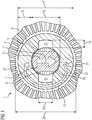
- Fig. 1 shows a schematic cross section of an electric machine 1 according to a first embodiment of the invention. Shown is a section of a hollow cylindrical stator 3 with a bore diameter 39, in the cavity of a rotor 5 is arranged.
- the rotor has an inner rotor core 7, on which an arrangement of a plurality of stacked electrical coil windings 9 is attached in this example.
- These electrical coil windings 9 form the excitation winding of the electric machine 1 and are in the considered embodiment as superconducting coil windings, here based on a ceramic high-temperature superconductor executed. They serve in this example to form a two-pole magnetic field whose course is symbolized within the rotor core with the arrow 11.
- the two poles of the magnetic field are in the upper and lower part of the in Fig. 1 imaged rotor core 7.
- the rotor core 7 with the superconducting elements arranged thereon Coil windings 9 forms the overall cylindrical inner rotor.
- This inner rotor is surrounded by a rotor shell 13, which has a hollow cylindrical basic shape.
- the hollow body of the rotor shell 13 has two diametrically opposed recesses 21, which in this example are also grooves in the axial direction over the length of the rotor shell 13 extend. In the first embodiment shown, the grooves are open and not filled with another solid.
- a narrow inner gap 35 is arranged in the example shown, which facilitates the assembly of the inner rotor in the rotor shell 13.
- This gap is only 1 mm wide, so that the rotor shell is guided very tightly around the inner rotor.
- At its two axial end sides it is mechanically connected to the inner rotor, so that it rotates synchronously with this in the interior of the stator 3 about the central axis of rotation 11.
- an outer gap 37 is filled in this example with air.
- the rotor shell 13 is formed of a soft magnetic material, in this example of a magnetic iron alloy. It serves to guide the bipolar magnetic field generated by the exciter winding 9.
- the radial flow component denoted by the arrow 31 is reinforced by the high permeability of the jacket material. This radial component 31 is also referred to as the useful flow in the region of the air gap 37. At the location of the stator 3, this radial component 31 continues and occurs there in electromagnetic interaction with arranged on the stator 3 further electrical coil windings. Also in the upper part of the Fig. 1 This results in an analogous to arrow 31 and rectified flow component, which is not shown here for clarity.
- the rotor jacket in the equatorial region between the two poles is provided with the two opposite recesses 21, which act as non-magnetic interruptions.
- the depth 23 of the recesses is advantageously more than half of the nominal thickness 15 of the rotor shell, so that the short-circuit component 33 of the magnetic flux is actually significantly reduced.
- the width 25 of the recesses is greater than the radial depth 23. In a two-pole machine, the width 25 of the recesses advantageously corresponds approximately to the height of the coil windings.
- the dimensions of the inner rotor and the rotor shell 13 may have very different sizes depending on the dimensions of the electric machine. It is essential that the thickness 15 of the rotor shell 13 is so large that the outer diameter of the inner rotor can be chosen substantially smaller than the inner diameter 39 of the stator. For this purpose, outer diameter 17 and inner diameter 19 of the rotor shell must differ significantly, for example, they may advantageously differ by at least 20%. In the example shown with an inner gap 35 between the inner rotor and the rotor shell, the outer diameter of the inner rotor is given as the difference between the inner diameter of the rotor shell and twice the gap width.
- Suitable values for the thickness 15 of the rotor shell 13 are, for example, above 5 cm.
- the outer diameter of the inner rotor can be reduced by about twice this thickness 15, which leads to a significant reduction of the centrifugal forces in the area of the electrical coil windings 9.
- the inner diameter 39 of the Stand 3 decoupled reduction of the inner rotor thus higher speed ranges for the electric machine 1 can be made accessible.
- the soft magnetic material of the rotor shell 13 and the embodiment with equatorial recesses 21 serves to produce a strong field magnetic field at the location of the stator despite this decoupling.
- the rotor shell 13 is formed of a cylindrical solid metal body with vacuum-tight walls.
- This rotor shell 13 is connected to the two axial end sides of the rotor 5 with not shown here also vacuum-tight side parts, so that the recesses 21 and the inner gap 35 are evacuated.
- the entire inner rotor can be kept at a very cold temperature close to the operating temperature of the superconducting coil windings 9, while the rotor shell 13 and the stator 3 surrounding it are at a warm ambient temperature.
- the inner gap 35 serves as the thermal insulation here, it can advantageously be made somewhat wider than if in other embodiments it only serves for the simplified assembly of the rotor shell 13 on the inner rotor.
- the mechanically rigid connection between the warm rotor shell 13 and cooled inner rotor can then be carried out expediently from thermally poorly conducting materials.
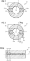
- Fig. 2 shows a schematic cross section of a rotor shell 13 according to a second embodiment of the invention.
- This rotor shell 13 can be used analogously to the rotor shell 13 of the first embodiment in an electric machine.
- two opposite equatorial recesses 21a are formed in the soft magnetic material of the rotor shell 13, which are configured in this example as radially continuous interruptions 21a.
- the interruptions 21a are here each filled with a filling 21b of non-magnetic material, so that a total of the two opposite segments of the soft magnetic material and the two arranged therebetween Filling a closed hollow cylindrical body 13 results.
- the interruptions 21a and the fillings 21b disposed therein extend axially over the full length of the rotor shell 13.
- the magnetic short-circuit component 33 can be particularly strongly suppressed in the rotor shell 13, without the mechanical strength of the rotor shell is significantly impaired.
- both the filler 21b and the interruptions 21a for example, matching dovetail cross-sectional profiles, so that the adjacent segments can be inserted into each other in the axial direction.
- the filler 21b can be mechanically connected to the other segments of the rotor shell 13, for example by glands, end-side glands and / or continuous pressure levels with frontal connecting rings.
- the non-magnetic material of the packing 21b may be, for example, a non-magnetic steel.
- the in Fig. 2 rotor shell 13 shown can be mechanically fixed in its axial end portions by connecting pieces with an inner runner arranged in its interior.
- Fig. 3 shows a schematic cross section of a rotor shell according to a third embodiment of the invention.
- the recesses 21a are each filled with a filling 21b of non-magnetic material.
- the recesses 21a do not extend over the entire radial thickness 15, but it remains in the outer region of a residual thickness 15a, which is small compared to the nominal thickness 15 of the rotor shell.
- this residual thickness 15a is only 5% to 50% of the nominal thickness 15.
- the recesses 21a are axially completely continuous grooves into which the filler pieces 21b can be inserted. Again, a design with dovetail allows easy installation with high mechanical strength.
- the magnetic short-circuit component 33 can also be relatively largely minimized in this exemplary embodiment as well.
- the smaller the residual thickness 15a the smaller the short-circuit component 33.
- An advantage of this configuration over that in Fig. 2 shown second embodiment lies in the greater mechanical strength, since the soft magnetic part of the rotor shell 13 consists of a continuous component.
- the rotor shell 13 at the same time serve well as a vacuum-tight envelope for thermal insulation for a cooled inner rotor, in contrast to the embodiment according to Fig. 2 in which this would be possible only with increased effort to seal the individual components of the rotor shell 13.
- Fig. 4 shows a schematic longitudinal section of a rotor shell 13 according to a fourth embodiment of the invention.
- the position of the section corresponds to that in Fig. 3 with IV marked cutting plane.
- the recesses 21a may have different cross-sectional shapes and need not be in the Fig. 3 have shown cross-section.
- the individual recesses 21a may be formed either as radially continuous interruptions or else as depressions with remaining residual thickness 15a of the rotor shell.
- the residual thickness 15a of the rotor shell 13 may in this case either stop on the inside or on the outside of the rotor shell 13 or be distributed over a plurality of radial sections.
- the recesses 21a are provided with filling pieces.
- the recesses 21a may also be evacuated as open, for example air-filled or together with the environment Cavities present.
- Such an arrangement with a plurality of axially spaced-apart recesses can be particularly advantageously provided in a rotor shell 13, which is formed from an axially stacked stack of a plurality of soft magnetic sheets. Then, a portion of the sheets can be provided with corresponding cavities, which then together form the recesses 21a of the sheet stack.
- axially continuous recesses 21a can also be formed in such a sheet stack.
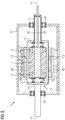
- Fig. 5 shows a central schematic longitudinal section of an electric machine according to a fifth embodiment of the invention. Shown is a stationary stator outer housing 41, in which the stator windings 43 are arranged on the inside of a hollow cylinder. Within this stator there is a rotor 5 rotatably mounted on a rotor shaft 45 with bearings 47.
- the rotor 5 comprises a soft-magnetic rotor core 7 on which superconducting coil windings 9 are arranged as field windings of the machine.
- the inner rotor formed from rotor core 7 and coil windings 9 is arranged in an inner vacuum tank 49, in which a vacuum V is present during operation of the machine.
- This vacuum V serves to thermally insulate the overall inner rotor at a cryogenic temperature level from its warm environment.
- the inner rotor is mechanically connected to the rotor shaft 45 with thermally poorly conducting connecting elements 53, so that a high temperature gradient can also be maintained via these connections.
- the rotor shaft 45 is mechanically fixedly connected to the inner vacuum container 49 via side members 51, so that this vacuum container rotates in synchronism with the rotor shaft 45 and the inner rotor.
- the rotor shell 13 On the outside of the vacuum container 49, the rotor shell 13 is now arranged, the soft magnetic material, the magnetic field of the field windings 9 leads to the location of the stator windings 43.
- the rotor shell 13 Due to the fixed connection with the vacuum container 49, the rotor shell 13 also rotates synchronously with the other components of the rotor 5. Again, the rotor shell 13 is similar to that described above with Recesses 21 provided, which are arranged between the poles of the field winding.
- the inner rotor is cooled by a coolant 55 circulating in the interior of the rotor shaft 45.
- the entire inner rotor with the superconducting coil windings 9 and the rotor core 7 is cooled to a temperature close to the operating temperature of the superconductor.
- the rotor shell 13, however, is located outside of the thermally insulating vacuum container 49 and is therefore kept at a significantly higher temperature level near the warm ambient temperature.
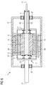
- FIG. 6 Another, alternative embodiment, this is schematically in Fig. 6 shown.
- the structure of the stator is analogous to Fig. 5 and also the components of the inner runner are similar.
- the rotor shell 13 is arranged in this example directly on the rotor core 7, which carries the field winding 9.
- An outer vacuum housing 57 is then arranged around the rotor shell 13 in such a way that the other components of the rotor 5 radially surround and bound the rotor to the outside.
- the vacuum housing 57 is connected to mechanically fixed connection parts 51 with the rotor shaft 45, so that the vacuum container rotates synchronously with the other parts of the rotor 5.
- the internal components are thermally isolated from the environment.
- Fig. 5 In contrast to Fig. 5 here is the rotor shell 13 in the inner region of the vacuum vessel and is cooled together with the rotor core 7 and the field windings 9 to a cold temperature level.
- the soft magnetic part of the rotor shell is formed of cold-forged magnetic steel.
- Fig. 5 and Fig. 6 Both examples in Fig. 5 and Fig. 6 is common that a large part of the distance between the inner surface of the stator and the outer surface of the inner rotor is filled at least in the region of the magnetic poles by soft magnetic material of the rotor shell 13. It should be emphasized that the size ratios in the Figures 5 and 6 not to scale. Much more In the case of real electrical machines 1, the gaps 35 and 37 will advantageously be substantially thinner than the nominal thickness 15 of the rotor jacket 13.
Landscapes
- Engineering & Computer Science (AREA)
- Power Engineering (AREA)
- Superconductive Dynamoelectric Machines (AREA)
Claims (13)
- Moteur (1) électrique, comprenant un stator (3) et un rotor (5) monté tournant autour d'un axe (11) de rotation,- dans lequel le rotor (5) a un noyau (7), qui se trouve à l'intérieur et qui est pourvu d'au moins un enroulement (9) de bobine électrique,- et dans lequel le noyau (7) du rotor et l'enroulement (9) de bobine sont entourés radialement d'une enveloppe (13) extérieure de rotor, qui est, au moins pour des parties majoritaires de son pourtour, en un matériau à magnétisme doux et qui a la forme de base d'un corps creux cylindrique de section circulaire ouvert des deux côtés,- caractérisé en ce que l'enveloppe (13) du rotor est pourvue d'au moins une paire d'évidements (21) opposés diamétralement et en ce que l'enroulement (9) de bobine est constitué pour produire un champ magnétique en ayant un nombre n pair de pôles, l'enveloppe (13) du rotor ayant au moins n paires d'évidements (21) opposés diamétralement respectivement et dans lequel ces évidements (21) sont disposés dans la direction du pourtour respectivement entre des pôles voisins.
- Moteur (1) électrique suivant la revendication 1, dans lequel l'enveloppe (13) du rotor a, au moins pour des parties majoritaires de son pourtour, une épaisseur (15) d'au moins 1 cm.
- Moteur (1) électrique suivant l'une des revendications 1 ou 2, dans lequel le diamètre (17) extérieur du corps creux est plus grand d'au moins 10% que le diamètre (19) intérieur du corps creux.
- Moteur (1) électrique suivant l'une des revendications précédentes, dans lequel l'enroulement (9) de bobine électrique du rotor (5) est constitué en enroulement de bobine supraconducteur.
- Moteur (1) électrique suivant l'une des revendications précédentes, dans lequel le matériau à magnétisme doux de l'enveloppe (13) du rotor a une perméabilité magnétique d'au moins 30.
- Moteur (1) électrique suivant l'une des revendications précédentes, dans lequel les évidements (21) sont constitués sous la forme d'évidements dans le matériau à magnétisme doux de l'enveloppe (13) du rotor, les évidements (21) étant remplis, au moins en partie, d'un matériau (21b) amagnétique.
- Moteur (1) électrique suivant l'une des revendications précédentes, dans lequel l'enveloppe (13) du rotor est pourvue de deux agencements opposés diamétralement de respectivement plusieurs évidements (21a) à distance dans la direction axiale.
- Moteur (1) électrique suivant l'une des revendications précédentes, dans lequel l'enveloppe (13) du rotor est pourvue d'au moins deux interruptions (21a) opposées diamétralement et respectivement continues radialement.
- Moteur (1) électrique suivant l'une des revendications précédentes, dans lequel un intervalle (35) intérieur est prévu entre le noyau (7) du rotor ayant l'enroulement (9) de bobine électrique et l'enveloppe (13) du rotor.
- Moteur (1) électrique suivant l'une des revendications précédentes, dans lequel l'enveloppe (13) du rotor entoure d'une manière étanche au vide le noyau (7) du rotor ayant l'enroulement (9) de bobine électrique.
- Moteur (1) électrique suivant l'une des revendications précédentes, dans lequel, entre le noyau (7) du rotor ayant l'enroulement (9) de bobine électrique et l'enveloppe (13) du rotor, est disposé un récipient (49) intérieur sous vide, qui entoure d'une manière étanche au vide le noyau (7) du rotor ayant l'enroulement (9) de bobine électrique.
- Moteur (1) électrique suivant l'une des revendications précédentes, dans lequel l'enveloppe (13) du rotor est entourée d'un récipient (57) extérieur sous vide.
- Moteur (1) électrique suivant l'une des revendications précédentes, dans lequel l'enroulement (9) de bobine électrique s'appuie sur le noyau (7) du rotor par au moins une boucle de maintien en un matériau mauvais conducteur de la chaleur.
Applications Claiming Priority (2)
| Application Number | Priority Date | Filing Date | Title |
|---|---|---|---|
| DE102014211029.7A DE102014211029A1 (de) | 2014-06-10 | 2014-06-10 | Elektrische Maschine für hohe Drehzahlen |
| PCT/EP2015/062656 WO2015189120A1 (fr) | 2014-06-10 | 2015-06-08 | Moteur electrique pour régimes élevés |
Publications (2)
| Publication Number | Publication Date |
|---|---|
| EP3130068A1 EP3130068A1 (fr) | 2017-02-15 |
| EP3130068B1 true EP3130068B1 (fr) | 2018-10-10 |
Family
ID=53396473
Family Applications (1)
| Application Number | Title | Priority Date | Filing Date |
|---|---|---|---|
| EP15728820.0A Not-in-force EP3130068B1 (fr) | 2014-06-10 | 2015-06-08 | Moteur electrique pour régimes élevés |
Country Status (4)
| Country | Link |
|---|---|
| US (1) | US20170149309A1 (fr) |
| EP (1) | EP3130068B1 (fr) |
| DE (1) | DE102014211029A1 (fr) |
| WO (1) | WO2015189120A1 (fr) |
Families Citing this family (2)
| Publication number | Priority date | Publication date | Assignee | Title |
|---|---|---|---|---|
| US10601299B2 (en) * | 2017-09-07 | 2020-03-24 | American Superconductor Corporation | High temperature superconductor generator with increased rotational inertia |
| GB2586989B (en) * | 2019-09-11 | 2022-07-27 | Rolls Royce Plc | Electric Machines |
Family Cites Families (9)
| Publication number | Priority date | Publication date | Assignee | Title |
|---|---|---|---|---|
| US3242418A (en) * | 1962-08-31 | 1966-03-22 | Dynatech Corp | Low temperature electromechanical transducer |
| US3742265A (en) * | 1972-05-25 | 1973-06-26 | Massachusetts Inst Technology | Superconducting apparatus with double armature structure |
| JP2586218B2 (ja) | 1990-12-07 | 1997-02-26 | トヨタ自動車株式会社 | 内燃機関の制御装置 |
| US5548168A (en) | 1994-06-29 | 1996-08-20 | General Electric Company | Superconducting rotor for an electrical machine |
| JPH09327159A (ja) * | 1996-06-04 | 1997-12-16 | Hitachi Ltd | 誘導機および誘導機システム |
| DE10110674A1 (de) | 2001-03-06 | 2002-09-26 | Siemens Ag | Maschine mit einer in einem Wicklungsträger angeordneten supraleitenden Wicklung sowie mit Mitteln zur Drehmomentübertragung von dem Wicklungsträger auf einen Wellenteil |
| DE10300269A1 (de) | 2003-01-08 | 2004-07-22 | Siemens Ag | Elektrische Maschine |
| US8664809B2 (en) | 2011-03-15 | 2014-03-04 | Siemens Energy, Inc. | Apparatus to support superconducting windings in a rotor of an electromotive machine |
| GB201107888D0 (en) * | 2011-05-12 | 2011-06-22 | Rolls Royce Plc | Superconducting electrical machine |
-
2014
- 2014-06-10 DE DE102014211029.7A patent/DE102014211029A1/de not_active Withdrawn
-
2015
- 2015-06-08 EP EP15728820.0A patent/EP3130068B1/fr not_active Not-in-force
- 2015-06-08 WO PCT/EP2015/062656 patent/WO2015189120A1/fr not_active Ceased
- 2015-06-08 US US15/316,662 patent/US20170149309A1/en not_active Abandoned
Non-Patent Citations (1)
| Title |
|---|
| None * |
Also Published As
| Publication number | Publication date |
|---|---|
| DE102014211029A1 (de) | 2015-12-17 |
| EP3130068A1 (fr) | 2017-02-15 |
| WO2015189120A1 (fr) | 2015-12-17 |
| US20170149309A1 (en) | 2017-05-25 |
Similar Documents
| Publication | Publication Date | Title |
|---|---|---|
| EP3491724B1 (fr) | Rotor comprenant un ensemble bobine et un support d'enroulements | |
| DE60019609T2 (de) | Supraleitender elektromotor | |
| DE102011121174B4 (de) | Elektrische Maschine, insbesondere für Luftfahrzeuge | |
| EP3231070B1 (fr) | Moteur électrique à excitation permanente | |
| DE2040760A1 (de) | Elektrische Synchronmaschine | |
| EP2929622B1 (fr) | Machine asynchrone à répartition optimisée des pertes électriques entre le stator et le rotor | |
| CH448243A (de) | Elektrische Maschine in Scheibenbauweise | |
| WO2018095903A1 (fr) | Machine synchrone à démultiplication magnétique de champ tournant et concentration de flux | |
| DE102020129142B4 (de) | Läufer für eine rotierende elektrische Maschine | |
| WO2010023106A2 (fr) | Machine électrique | |
| EP3769408A1 (fr) | Dispositif de bobine électrique supraconducteur et rotor comprenant un dispositif de bobine | |
| DE112014002763T5 (de) | Elektrische Rotationsmaschine | |
| DE2418260A1 (de) | Rotor mit tiefgekuehlter erregerwicklung | |
| DE102015204872A1 (de) | Käfigläufer für eine elektrische Asynchronmaschine mit einen Kurzschlussring stabilisierenden Zugankern | |
| EP3130068B1 (fr) | Moteur electrique pour régimes élevés | |
| DE102023129635A1 (de) | Hybrid erregte rotierende maschine | |
| WO2020069908A1 (fr) | Rotor et machine comprenant un aimant permanent supraconducteur | |
| WO2020038909A1 (fr) | Rotor comprenant un enroulement supraconducteur pour le fonctionnement en mode électrique permanent | |
| DE102016222481A1 (de) | Rotor für hohe Drehzahlen mit Spulenanordnung und Wicklungsträger | |
| DE102014212035A1 (de) | Elektrische Maschine | |
| DE19804208A1 (de) | Elektrischer Turbogenerator | |
| WO2015135765A1 (fr) | Rotor de machine électrique tournante | |
| DE102009044945A1 (de) | Polumschaltbare elektrische Maschine | |
| DE2355082C3 (de) | Umlaufende elektrische Maschine mit einem eine supraleitende Wicklung aufweisenden Rotor | |
| EP3776827A1 (fr) | Rotor et machine comprenant un corps de support cylindrique |
Legal Events
| Date | Code | Title | Description |
|---|---|---|---|
| STAA | Information on the status of an ep patent application or granted ep patent |
Free format text: STATUS: THE INTERNATIONAL PUBLICATION HAS BEEN MADE |
|
| PUAI | Public reference made under article 153(3) epc to a published international application that has entered the european phase |
Free format text: ORIGINAL CODE: 0009012 |
|
| STAA | Information on the status of an ep patent application or granted ep patent |
Free format text: STATUS: REQUEST FOR EXAMINATION WAS MADE |
|
| 17P | Request for examination filed |
Effective date: 20161108 |
|
| AK | Designated contracting states |
Kind code of ref document: A1 Designated state(s): AL AT BE BG CH CY CZ DE DK EE ES FI FR GB GR HR HU IE IS IT LI LT LU LV MC MK MT NL NO PL PT RO RS SE SI SK SM TR |
|
| AX | Request for extension of the european patent |
Extension state: BA ME |
|
| RAP1 | Party data changed (applicant data changed or rights of an application transferred) |
Owner name: SIEMENS AKTIENGESELLSCHAFT |
|
| DAV | Request for validation of the european patent (deleted) | ||
| DAX | Request for extension of the european patent (deleted) | ||
| GRAP | Despatch of communication of intention to grant a patent |
Free format text: ORIGINAL CODE: EPIDOSNIGR1 |
|
| STAA | Information on the status of an ep patent application or granted ep patent |
Free format text: STATUS: GRANT OF PATENT IS INTENDED |
|
| INTG | Intention to grant announced |
Effective date: 20180608 |
|
| GRAS | Grant fee paid |
Free format text: ORIGINAL CODE: EPIDOSNIGR3 |
|
| GRAA | (expected) grant |
Free format text: ORIGINAL CODE: 0009210 |
|
| STAA | Information on the status of an ep patent application or granted ep patent |
Free format text: STATUS: THE PATENT HAS BEEN GRANTED |
|
| AK | Designated contracting states |
Kind code of ref document: B1 Designated state(s): AL AT BE BG CH CY CZ DE DK EE ES FI FR GB GR HR HU IE IS IT LI LT LU LV MC MK MT NL NO PL PT RO RS SE SI SK SM TR |
|
| REG | Reference to a national code |
Ref country code: GB Ref legal event code: FG4D Free format text: NOT ENGLISH |
|
| REG | Reference to a national code |
Ref country code: CH Ref legal event code: EP Ref country code: AT Ref legal event code: REF Ref document number: 1052394 Country of ref document: AT Kind code of ref document: T Effective date: 20181015 |
|
| REG | Reference to a national code |
Ref country code: IE Ref legal event code: FG4D Free format text: LANGUAGE OF EP DOCUMENT: GERMAN Ref country code: DE Ref legal event code: R096 Ref document number: 502015006335 Country of ref document: DE |
|
| REG | Reference to a national code |
Ref country code: NL Ref legal event code: MP Effective date: 20181010 |
|
| REG | Reference to a national code |
Ref country code: LT Ref legal event code: MG4D |
|
| PG25 | Lapsed in a contracting state [announced via postgrant information from national office to epo] |
Ref country code: NL Free format text: LAPSE BECAUSE OF FAILURE TO SUBMIT A TRANSLATION OF THE DESCRIPTION OR TO PAY THE FEE WITHIN THE PRESCRIBED TIME-LIMIT Effective date: 20181010 |
|
| PG25 | Lapsed in a contracting state [announced via postgrant information from national office to epo] |
Ref country code: IS Free format text: LAPSE BECAUSE OF FAILURE TO SUBMIT A TRANSLATION OF THE DESCRIPTION OR TO PAY THE FEE WITHIN THE PRESCRIBED TIME-LIMIT Effective date: 20190210 Ref country code: FI Free format text: LAPSE BECAUSE OF FAILURE TO SUBMIT A TRANSLATION OF THE DESCRIPTION OR TO PAY THE FEE WITHIN THE PRESCRIBED TIME-LIMIT Effective date: 20181010 Ref country code: HR Free format text: LAPSE BECAUSE OF FAILURE TO SUBMIT A TRANSLATION OF THE DESCRIPTION OR TO PAY THE FEE WITHIN THE PRESCRIBED TIME-LIMIT Effective date: 20181010 Ref country code: NO Free format text: LAPSE BECAUSE OF FAILURE TO SUBMIT A TRANSLATION OF THE DESCRIPTION OR TO PAY THE FEE WITHIN THE PRESCRIBED TIME-LIMIT Effective date: 20190110 Ref country code: LV Free format text: LAPSE BECAUSE OF FAILURE TO SUBMIT A TRANSLATION OF THE DESCRIPTION OR TO PAY THE FEE WITHIN THE PRESCRIBED TIME-LIMIT Effective date: 20181010 Ref country code: BG Free format text: LAPSE BECAUSE OF FAILURE TO SUBMIT A TRANSLATION OF THE DESCRIPTION OR TO PAY THE FEE WITHIN THE PRESCRIBED TIME-LIMIT Effective date: 20190110 Ref country code: LT Free format text: LAPSE BECAUSE OF FAILURE TO SUBMIT A TRANSLATION OF THE DESCRIPTION OR TO PAY THE FEE WITHIN THE PRESCRIBED TIME-LIMIT Effective date: 20181010 Ref country code: PL Free format text: LAPSE BECAUSE OF FAILURE TO SUBMIT A TRANSLATION OF THE DESCRIPTION OR TO PAY THE FEE WITHIN THE PRESCRIBED TIME-LIMIT Effective date: 20181010 Ref country code: ES Free format text: LAPSE BECAUSE OF FAILURE TO SUBMIT A TRANSLATION OF THE DESCRIPTION OR TO PAY THE FEE WITHIN THE PRESCRIBED TIME-LIMIT Effective date: 20181010 |
|
| PG25 | Lapsed in a contracting state [announced via postgrant information from national office to epo] |
Ref country code: AL Free format text: LAPSE BECAUSE OF FAILURE TO SUBMIT A TRANSLATION OF THE DESCRIPTION OR TO PAY THE FEE WITHIN THE PRESCRIBED TIME-LIMIT Effective date: 20181010 Ref country code: PT Free format text: LAPSE BECAUSE OF FAILURE TO SUBMIT A TRANSLATION OF THE DESCRIPTION OR TO PAY THE FEE WITHIN THE PRESCRIBED TIME-LIMIT Effective date: 20190210 Ref country code: GR Free format text: LAPSE BECAUSE OF FAILURE TO SUBMIT A TRANSLATION OF THE DESCRIPTION OR TO PAY THE FEE WITHIN THE PRESCRIBED TIME-LIMIT Effective date: 20190111 Ref country code: SE Free format text: LAPSE BECAUSE OF FAILURE TO SUBMIT A TRANSLATION OF THE DESCRIPTION OR TO PAY THE FEE WITHIN THE PRESCRIBED TIME-LIMIT Effective date: 20181010 Ref country code: RS Free format text: LAPSE BECAUSE OF FAILURE TO SUBMIT A TRANSLATION OF THE DESCRIPTION OR TO PAY THE FEE WITHIN THE PRESCRIBED TIME-LIMIT Effective date: 20181010 |
|
| REG | Reference to a national code |
Ref country code: DE Ref legal event code: R097 Ref document number: 502015006335 Country of ref document: DE |
|
| PG25 | Lapsed in a contracting state [announced via postgrant information from national office to epo] |
Ref country code: IT Free format text: LAPSE BECAUSE OF FAILURE TO SUBMIT A TRANSLATION OF THE DESCRIPTION OR TO PAY THE FEE WITHIN THE PRESCRIBED TIME-LIMIT Effective date: 20181010 Ref country code: CZ Free format text: LAPSE BECAUSE OF FAILURE TO SUBMIT A TRANSLATION OF THE DESCRIPTION OR TO PAY THE FEE WITHIN THE PRESCRIBED TIME-LIMIT Effective date: 20181010 Ref country code: DK Free format text: LAPSE BECAUSE OF FAILURE TO SUBMIT A TRANSLATION OF THE DESCRIPTION OR TO PAY THE FEE WITHIN THE PRESCRIBED TIME-LIMIT Effective date: 20181010 |
|
| PLBE | No opposition filed within time limit |
Free format text: ORIGINAL CODE: 0009261 |
|
| STAA | Information on the status of an ep patent application or granted ep patent |
Free format text: STATUS: NO OPPOSITION FILED WITHIN TIME LIMIT |
|
| PG25 | Lapsed in a contracting state [announced via postgrant information from national office to epo] |
Ref country code: SM Free format text: LAPSE BECAUSE OF FAILURE TO SUBMIT A TRANSLATION OF THE DESCRIPTION OR TO PAY THE FEE WITHIN THE PRESCRIBED TIME-LIMIT Effective date: 20181010 Ref country code: EE Free format text: LAPSE BECAUSE OF FAILURE TO SUBMIT A TRANSLATION OF THE DESCRIPTION OR TO PAY THE FEE WITHIN THE PRESCRIBED TIME-LIMIT Effective date: 20181010 Ref country code: RO Free format text: LAPSE BECAUSE OF FAILURE TO SUBMIT A TRANSLATION OF THE DESCRIPTION OR TO PAY THE FEE WITHIN THE PRESCRIBED TIME-LIMIT Effective date: 20181010 Ref country code: SK Free format text: LAPSE BECAUSE OF FAILURE TO SUBMIT A TRANSLATION OF THE DESCRIPTION OR TO PAY THE FEE WITHIN THE PRESCRIBED TIME-LIMIT Effective date: 20181010 |
|
| 26N | No opposition filed |
Effective date: 20190711 |
|
| PG25 | Lapsed in a contracting state [announced via postgrant information from national office to epo] |
Ref country code: SI Free format text: LAPSE BECAUSE OF FAILURE TO SUBMIT A TRANSLATION OF THE DESCRIPTION OR TO PAY THE FEE WITHIN THE PRESCRIBED TIME-LIMIT Effective date: 20181010 |
|
| REG | Reference to a national code |
Ref country code: DE Ref legal event code: R119 Ref document number: 502015006335 Country of ref document: DE |
|
| PG25 | Lapsed in a contracting state [announced via postgrant information from national office to epo] |
Ref country code: MC Free format text: LAPSE BECAUSE OF FAILURE TO SUBMIT A TRANSLATION OF THE DESCRIPTION OR TO PAY THE FEE WITHIN THE PRESCRIBED TIME-LIMIT Effective date: 20181010 |
|
| REG | Reference to a national code |
Ref country code: CH Ref legal event code: PL |
|
| GBPC | Gb: european patent ceased through non-payment of renewal fee |
Effective date: 20190608 |
|
| REG | Reference to a national code |
Ref country code: BE Ref legal event code: MM Effective date: 20190630 |
|
| PG25 | Lapsed in a contracting state [announced via postgrant information from national office to epo] |
Ref country code: TR Free format text: LAPSE BECAUSE OF FAILURE TO SUBMIT A TRANSLATION OF THE DESCRIPTION OR TO PAY THE FEE WITHIN THE PRESCRIBED TIME-LIMIT Effective date: 20181010 |
|
| PG25 | Lapsed in a contracting state [announced via postgrant information from national office to epo] |
Ref country code: DE Free format text: LAPSE BECAUSE OF NON-PAYMENT OF DUE FEES Effective date: 20200101 Ref country code: GB Free format text: LAPSE BECAUSE OF NON-PAYMENT OF DUE FEES Effective date: 20190608 Ref country code: IE Free format text: LAPSE BECAUSE OF NON-PAYMENT OF DUE FEES Effective date: 20190608 |
|
| PG25 | Lapsed in a contracting state [announced via postgrant information from national office to epo] |
Ref country code: CH Free format text: LAPSE BECAUSE OF NON-PAYMENT OF DUE FEES Effective date: 20190630 Ref country code: LI Free format text: LAPSE BECAUSE OF NON-PAYMENT OF DUE FEES Effective date: 20190630 Ref country code: LU Free format text: LAPSE BECAUSE OF NON-PAYMENT OF DUE FEES Effective date: 20190608 Ref country code: BE Free format text: LAPSE BECAUSE OF NON-PAYMENT OF DUE FEES Effective date: 20190630 |
|
| PG25 | Lapsed in a contracting state [announced via postgrant information from national office to epo] |
Ref country code: FR Free format text: LAPSE BECAUSE OF NON-PAYMENT OF DUE FEES Effective date: 20190630 |
|
| PG25 | Lapsed in a contracting state [announced via postgrant information from national office to epo] |
Ref country code: CY Free format text: LAPSE BECAUSE OF FAILURE TO SUBMIT A TRANSLATION OF THE DESCRIPTION OR TO PAY THE FEE WITHIN THE PRESCRIBED TIME-LIMIT Effective date: 20181010 |
|
| PG25 | Lapsed in a contracting state [announced via postgrant information from national office to epo] |
Ref country code: MT Free format text: LAPSE BECAUSE OF FAILURE TO SUBMIT A TRANSLATION OF THE DESCRIPTION OR TO PAY THE FEE WITHIN THE PRESCRIBED TIME-LIMIT Effective date: 20181010 Ref country code: HU Free format text: LAPSE BECAUSE OF FAILURE TO SUBMIT A TRANSLATION OF THE DESCRIPTION OR TO PAY THE FEE WITHIN THE PRESCRIBED TIME-LIMIT; INVALID AB INITIO Effective date: 20150608 |
|
| REG | Reference to a national code |
Ref country code: AT Ref legal event code: MM01 Ref document number: 1052394 Country of ref document: AT Kind code of ref document: T Effective date: 20200608 |
|
| PG25 | Lapsed in a contracting state [announced via postgrant information from national office to epo] |
Ref country code: AT Free format text: LAPSE BECAUSE OF NON-PAYMENT OF DUE FEES Effective date: 20200608 |
|
| PG25 | Lapsed in a contracting state [announced via postgrant information from national office to epo] |
Ref country code: MK Free format text: LAPSE BECAUSE OF FAILURE TO SUBMIT A TRANSLATION OF THE DESCRIPTION OR TO PAY THE FEE WITHIN THE PRESCRIBED TIME-LIMIT Effective date: 20181010 |