EP3130204B1 - Dispositif d'allumage pour hid lampe - Google Patents
Dispositif d'allumage pour hid lampe Download PDFInfo
- Publication number
- EP3130204B1 EP3130204B1 EP15713774.6A EP15713774A EP3130204B1 EP 3130204 B1 EP3130204 B1 EP 3130204B1 EP 15713774 A EP15713774 A EP 15713774A EP 3130204 B1 EP3130204 B1 EP 3130204B1
- Authority
- EP
- European Patent Office
- Prior art keywords
- temperature
- ignitor
- arrangement
- lamp
- pair
- Prior art date
- Legal status (The legal status is an assumption and is not a legal conclusion. Google has not performed a legal analysis and makes no representation as to the accuracy of the status listed.)
- Active
Links
- 230000001419 dependent effect Effects 0.000 claims description 29
- 238000011156 evaluation Methods 0.000 claims description 24
- 238000000034 method Methods 0.000 claims description 11
- 230000001105 regulatory effect Effects 0.000 claims description 11
- 239000003990 capacitor Substances 0.000 claims description 9
- 230000008859 change Effects 0.000 description 7
- 230000008901 benefit Effects 0.000 description 5
- 238000010586 diagram Methods 0.000 description 5
- 230000007423 decrease Effects 0.000 description 4
- 230000004075 alteration Effects 0.000 description 3
- 238000013459 approach Methods 0.000 description 3
- 230000006378 damage Effects 0.000 description 3
- 230000006870 function Effects 0.000 description 3
- 229910052724 xenon Inorganic materials 0.000 description 3
- FHNFHKCVQCLJFQ-UHFFFAOYSA-N xenon atom Chemical compound [Xe] FHNFHKCVQCLJFQ-UHFFFAOYSA-N 0.000 description 3
- 230000033228 biological regulation Effects 0.000 description 2
- 238000013461 design Methods 0.000 description 2
- 238000011161 development Methods 0.000 description 2
- 238000012544 monitoring process Methods 0.000 description 2
- 238000004804 winding Methods 0.000 description 2
- XUIMIQQOPSSXEZ-UHFFFAOYSA-N Silicon Chemical compound [Si] XUIMIQQOPSSXEZ-UHFFFAOYSA-N 0.000 description 1
- 230000000712 assembly Effects 0.000 description 1
- 238000000429 assembly Methods 0.000 description 1
- 230000015556 catabolic process Effects 0.000 description 1
- 230000000694 effects Effects 0.000 description 1
- 230000002349 favourable effect Effects 0.000 description 1
- 238000001914 filtration Methods 0.000 description 1
- 230000002452 interceptive effect Effects 0.000 description 1
- 238000002955 isolation Methods 0.000 description 1
- 238000004519 manufacturing process Methods 0.000 description 1
- 230000013011 mating Effects 0.000 description 1
- 238000013021 overheating Methods 0.000 description 1
- 230000009467 reduction Effects 0.000 description 1
- 230000004044 response Effects 0.000 description 1
- 229910052710 silicon Inorganic materials 0.000 description 1
- 239000010703 silicon Substances 0.000 description 1
- 238000012360 testing method Methods 0.000 description 1
- 230000003685 thermal hair damage Effects 0.000 description 1
- 230000008646 thermal stress Effects 0.000 description 1
Images


Classifications
-
- H—ELECTRICITY
- H05—ELECTRIC TECHNIQUES NOT OTHERWISE PROVIDED FOR
- H05B—ELECTRIC HEATING; ELECTRIC LIGHT SOURCES NOT OTHERWISE PROVIDED FOR; CIRCUIT ARRANGEMENTS FOR ELECTRIC LIGHT SOURCES, IN GENERAL
- H05B41/00—Circuit arrangements or apparatus for igniting or operating discharge lamps
- H05B41/14—Circuit arrangements
- H05B41/26—Circuit arrangements in which the lamp is fed by power derived from DC by means of a converter, e.g. by high-voltage DC
- H05B41/28—Circuit arrangements in which the lamp is fed by power derived from DC by means of a converter, e.g. by high-voltage DC using static converters
- H05B41/288—Circuit arrangements in which the lamp is fed by power derived from DC by means of a converter, e.g. by high-voltage DC using static converters with semiconductor devices and specially adapted for lamps without preheating electrodes, e.g. for high-intensity discharge lamps, high-pressure mercury or sodium lamps or low-pressure sodium lamps
- H05B41/292—Arrangements for protecting lamps or circuits against abnormal operating conditions
- H05B41/2921—Arrangements for protecting lamps or circuits against abnormal operating conditions for protecting the circuit against abnormal operating conditions
- H05B41/2926—Arrangements for protecting lamps or circuits against abnormal operating conditions for protecting the circuit against abnormal operating conditions against internal abnormal circuit conditions
-
- H—ELECTRICITY
- H05—ELECTRIC TECHNIQUES NOT OTHERWISE PROVIDED FOR
- H05B—ELECTRIC HEATING; ELECTRIC LIGHT SOURCES NOT OTHERWISE PROVIDED FOR; CIRCUIT ARRANGEMENTS FOR ELECTRIC LIGHT SOURCES, IN GENERAL
- H05B41/00—Circuit arrangements or apparatus for igniting or operating discharge lamps
- H05B41/14—Circuit arrangements
- H05B41/26—Circuit arrangements in which the lamp is fed by power derived from DC by means of a converter, e.g. by high-voltage DC
- H05B41/28—Circuit arrangements in which the lamp is fed by power derived from DC by means of a converter, e.g. by high-voltage DC using static converters
- H05B41/288—Circuit arrangements in which the lamp is fed by power derived from DC by means of a converter, e.g. by high-voltage DC using static converters with semiconductor devices and specially adapted for lamps without preheating electrodes, e.g. for high-intensity discharge lamps, high-pressure mercury or sodium lamps or low-pressure sodium lamps
- H05B41/2881—Load circuits; Control thereof
-
- Y—GENERAL TAGGING OF NEW TECHNOLOGICAL DEVELOPMENTS; GENERAL TAGGING OF CROSS-SECTIONAL TECHNOLOGIES SPANNING OVER SEVERAL SECTIONS OF THE IPC; TECHNICAL SUBJECTS COVERED BY FORMER USPC CROSS-REFERENCE ART COLLECTIONS [XRACs] AND DIGESTS
- Y02—TECHNOLOGIES OR APPLICATIONS FOR MITIGATION OR ADAPTATION AGAINST CLIMATE CHANGE
- Y02B—CLIMATE CHANGE MITIGATION TECHNOLOGIES RELATED TO BUILDINGS, e.g. HOUSING, HOUSE APPLIANCES OR RELATED END-USER APPLICATIONS
- Y02B20/00—Energy efficient lighting technologies, e.g. halogen lamps or gas discharge lamps
Definitions
- the invention describes an ignitor arrangement for a high-intensity discharge lamp; a lamp driver; a lighting arrangement; and a method of driving a high-intensity discharge lamp.
- a high-intensity discharge lamp (HID lamp) - such as an automotive Xenon lamp for a front beam - may be realised together with an ignitor, i.e. the lamp is mounted to the ignitor housing and is electrically connected to components inside the ignitor housing.
- Lamp and ignitor may be realised as a single product, with the lamp mounted directly to a housing containing the ignitor components.
- the ignitor housing generally has a connection interface for connecting a number of electrical leads to an electronic lamp driver.
- the ignitor generally comprises a transformer, an ignition capacitor, a voltage limiter such as a clipping diode, a discharge resistor and a spark gap.
- the purpose of the ignitor is to establish a discharge arc across the tips of the electrodes inside the discharge chamber of the lamp (also referred to as a "burner") so that normal or steady-state operation can begin.
- a known type of ignitor such as an asymmetrical ignitor comprises a pair of input terminals for applying the ignition voltage, and a pair of terminals for applying a drive voltage to the lamp during steady-state operation.
- the lamp driver is used to regulate the lamp power.
- some electronic lamp drivers for automotive HID lamps are designed and manufactured to be able to increase the lamp power in such a situation.
- lamps may be designed to consume more power, for example in an upper power limit allowed by the appropriate regulation. Increasing the lamp power for whatever reason leads to an increase in the temperature inside the ignitor housing, and the components of the ignitor may become damaged as a result. For example, if the lamp is driven at a boosted or higher power that is greater than the lamp's nominal power, the ignitor components are subjected to increased thermal stress.
- a temperature sensor can be arranged inside the ignitor housing and connected by electrical leads to an external module that monitors the temperature development and regulates the lamp power accordingly.
- this solution requires an alteration to an existing interface between the ignitor and the lamp driver in order to accommodate the additional electrical leads, and is therefore unattractive from a commercial point of view.
- heat-dissipating elements can be mounted to the outside of the ignitor housing in order to draw some heat away from the ignitor and its components, and/or a ventilator may be used to blow cool air over the ignitor.
- a ventilator may be used to blow cool air over the ignitor.
- the object of the invention is achieved by the ignitor arrangement of claim 1; by the lamp driver of claim 5; by the lighting arrangement of claim 9; and by the method of claim 10 of driving a high-intensity discharge lamp.
- the ignitor arrangement for a high-intensity discharge lamp comprises a first pair of input terminals for applying an ignition voltage to the ignitor arrangement; a second pair of input terminals for applying an input drive voltage to the ignitor arrangement; and a discharge resistor arranged in the interior of a housing of the ignitor arrangement and connected across the first input terminal pair, characterized in that the discharge resistor is realised as a temperature-dependent resistor.
- the ignitor arrangement will comprise further elements for igniting the lamp, as well as a pair of output terminals for applying an output drive voltage to the lamp.
- An advantage of the ignitor arrangement according to the invention is that the temperature-dependent resistor can be used to obtain information directly relating to the temperature in the interior of the ignitor arrangement. Since the resistance of the temperature-dependent resistor changes as temperature increases or decreases, and since resistance can be measured relatively easily, the temperature-dependent resistor can be used to determine the temperature in the ignitor, and the operating power of the lamp can be regulated accordingly. For example, the lamp power can be regulated by adjusting the current supplied to the lamp via the second pair of input terminals.
- An ignitor such as an asymmetrical ignitor for a HID lamp incorporates a discharge resistor, which serves the purpose of providing a discharge path for the capacitor that is used to generate a spark across a spark gap.
- this functionality of the discharge resistor remains unchanged, and this discharge resistor now also fulfils an additional function, namely that of providing favourably accurate feedback regarding the temperature inside the ignitor. In this way, a regulation of the temperature in the interior of the ignitor arrangement can be achieved without having to alter or adapt an existing ignitor/driver interface or the actual ignitor design.
- the ignitor arrangement according to the invention favourably makes use of the ignition terminal, which is no longer required for any specific purpose during steady-state operation of the lamp.
- the ignitor arrangement according to the invention does not need any additional component or sensing arrangement, and no alteration is needed to an interface between the ignitor and the driver. Therefore, the ignitor arrangement according to the invention is favourably economical to manufacture.
- the ignitor arrangement according to the invention is characterized by an extended lifetime since the components inside the ignitor housing can be protected from heat damage, as will be explained below.
- the lamp driver is realised to drive a high-intensity discharge lamp, preferably an automotive lamp, and comprises an ignitor arrangement according to the invention; an ignition circuit realised to apply an ignition voltage across the first pair of input terminals of the ignitor arrangement; a drive circuit realised to apply a drive voltage across the second pair of input terminals of the ignitor arrangement; a temperature evaluation unit realised to determine a temperature in the interior of the ignitor arrangement; and a control unit for regulating the lamp's operating power on the basis of the determined temperature.
- An advantage of the lamp driver according to the invention is that it can easily be provided with information relating to the momentary thermal situation inside the ignitor, so that it can respond appropriately. For example, in case of interior conditions that are too hot, the lamp driver can respond by lowering the lamp power. On the other hand, if the temperature inside the ignitor appears to have some 'headroom', and additional lamp power would be of advantage, the lamp driver can increase the lamp power without risking thermal damage to the ignitor components.
- the lighting arrangement comprises an ignitor arrangement according to the invention arranged in the interior of a housing; and a high-intensity discharge lamp mounted onto the housing, whereby an electrode pair of the lamp is connected to the output terminal pair of the ignitor arrangement.
- An advantage of the lighting arrangement according to the invention is that it can have a significantly longer lifetime than a comparable lighting arrangement without such a temperature-dependent resistor incorporated in the ignitor interior, and that this additional lifetime can be obtained without having to make any alterations on an interface between the lighting arrangement and a lamp driver.
- the method of driving a high-intensity discharge lamp comprises the steps of connecting the lamp to an ignitor arrangement according to the invention; applying an ignition voltage across the first pair of input terminals of the ignitor arrangement in order to ignite the lamp; applying a drive voltage across the second pair of input terminals of the ignitor arrangement after lamp ignition; determining a temperature in the interior of the ignitor arrangement; and regulating the operating power on the basis of the determined temperature.
- An advantage of the method according to the invention is that the temperature in the interior of the ignitor arrangement can be established or determined in a very simple and convenient manner, without having to arrange temperature sensors inside the ignitor.
- the lamp driver can, at any time, determine the temperature inside the ignitor and can regulate the lamp power accordingly if necessary.
- the method according to the invention allows the lamp driver to determine whether it is safe to drive the lamp at a higher power, should this be desired, since it is easy to determine whether the ignitor interior temperature is low enough to be able to deal with an increased burner temperature.
- the lamp or burner is a high-intensity discharge (HID) lamp of the type used in an automotive application, such as a front headlamp, and the terms “lamp” and “burner” may be used interchangeably in the following.
- An example of such a burner might be a Xenon HID lamp, which can be mounted directly to an ignitor.
- a lighting arrangement comprising such an HID lamp and ignitor generally has a defined interface with a connector for mating with a connector of a lamp driver, so that the entire lighting arrangement can be easily replaced while ensuring that the burner is placed in a defined orientation or position in the headlamp.
- the terms "temperature-dependent discharge resistor”, “temperature-dependent resistor” and “thermistor” may be used interchangeably in the following.
- a temperature-dependent discharge resistor such as a negative temperature coefficient (NTC) thermistor could be used, or a positive temperature coefficient (PTC) thermistor, or a thermally sensitive silicon resistor, usually referred to as a silistor.
- NTC negative temperature coefficient
- PTC positive temperature coefficient
- silistor thermally sensitive silicon resistor
- the resistance of a temperature dependent resistor alters with increasing temperature of the resistor.
- the resistance of an NTC thermistor decreases with increasing temperature.
- the relationship between temperature and resistance is generally nonlinear, or may be linear only over quite small temperature ranges. Usually, the relationship between resistance and temperature is described using a third-order approximation.
- the temperature-dependent discharge resistor is chosen on the basis of a known temperature in the ignitor interior during normal operating conditions of the lamp.
- Normal operating conditions may be understood to mean operation at a nominal or rated lamp power within a certain ambient temperature range.
- the thermistor's value of resistance may be the same as the value of the resistor that it replaces. For example, if a resistor of 6 M ⁇ is being replaced by an NTC thermistor, and the nominal operating power of the lamp is 35 W, the thermistor should have a similar resistance at the temperatures that are typical for operation at that power level. Furthermore, the resistance of the thermistor should clearly change when the temperature in the ignitor increases as the lamp is driven at a higher power, so that such a change is detectable and can be used to deduce or estimate the temperature in the ignitor interior.
- a thermistor is used that has a defined relationship between resistance and temperature at least over the temperature range from 25°C to 150°C.
- the temperature evaluation unit is preferably connected across the temperature-dependent discharge resistor, so that it can evaluate a voltage across the temperature-dependent discharge resistor and/or a current through the temperature-dependent discharge resistor.
- the information provided by the temperature-dependent discharge resistor - i.e. the change in resistance that follows a change in the temperature in the ignitor interior - can be evaluated or used in a number of ways. For example, a known voltage can be applied across the thermistor, and the resulting current through the thermistor can be measured, from which the resistance of the thermistor can be calculated. Since an essentially constant voltage is generally applied across the shared terminal and the ignition terminal during steady-state lamp operation in any case, this fact is put to good use by the lamp driver according to the invention.
- the current through the thermistor can be measured. Any change in resistance will result in a change in the measured current. For example, if the thermistor is an NTC thermistor, its resistance decreases with temperature. Therefore, a higher measured current will indicate a decrease in resistance and therefore also an increase in temperature.
- the altered resistance of the thermistor can be determined using Ohm's law and the values of known voltage and measured current, and the temperature inside the ignitor can subsequently be estimated with a suitable algorithm.
- the lamp driver may be equipped with a processor that can compute the resistance of the thermistor on the basis of the measured current, and may then use this to solve a third-order approximation relating resistance to temperature, in order to calculate the momentary temperature.
- the temperature evaluation unit is provided with information relating values of measured current to values of temperature. The information can be collected in advance during a calibration or test setup for a driver/ignitor combination. This information can be provided in the form of one or more look-up tables made available to the temperature evaluation unit of the lamp driver.
- the current applied across the shared terminal and the ignition terminal may be essentially constant, and the temperature evaluation unit may be able to measure the voltage across the thermistor.
- any change in resistance of the thermistor can be determined using Ohm's law and the values of measured voltage and known current, so that the temperature inside the ignitor can subsequently be estimated.
- information relating voltage to temperature for a certain constant current can be collected for a particular thermistor during a calibration stage for a driver/ignitor combination, and provided in the form of one or more look-up tables made available to the temperature evaluation unit of the lamp driver.
- the temperature evaluation unit can be realised to operate on the basis of a voltage divider.
- the temperature-dependent discharge resistor of the ignitor arrangement and a fixed-value resistor in the temperature evaluation unit could be connected as a voltage divider.
- a known voltage can be applied across the voltage divider, and the output voltage can be measured using the ignition terminal.
- the temperature in the ignitor interior can be monitored by the control unit in any suitable fashion.
- the control unit may perform a temperature estimation every ten minutes or at any other suitable interval.
- the control unit is realised to essentially continuously monitor the temperature of the ignitor arrangement. In this way, the driver can respond quickly to a rapid increase in temperature in the ignitor interior space by regulating the lamp power. Equally, the control unit and driver can act to prevent the components of the ignitor from being exposed to overly high temperatures for any length of time.
- the estimated or calculated ignitor interior temperature can be used to determine whether any adjustment should be made in how the lamp is being driven.
- the step of regulating the lamp's operating power is performed such that the temperature in the interior of the ignitor arrangement is maintained below an upper temperature limit. For example, if the ignitor interior temperature is found to be close to this upper temperature limit, the lamp power can be reduced until the temperature drops to a satisfactory level. Equally, if the estimated temperature indicates a favourable amount of 'headroom' below the upper temperature limit, the lamp driver may increase the lamp's operating power if desired, while continuing to monitor the ignitor interior temperature.
- Fig 1 shows an embodiment of a lighting arrangement 4 according to the invention, with a HID lamp burner 2 mounted to and electrically connected to an ignitor arrangement 1 according to the invention.
- the ignitor arrangement 1 is realised as an asymmetrical automotive ignitor 1, and the lamp 2 can be a HID burner 2 for a front lighting application.
- the lighting arrangement 4 can be realised, for example, as a D1 or D3 application.
- the ignitor arrangement 1 has a pair of input terminals 101, 102 to which an ignition voltage is applied (by a lamp driver, not shown here), and another pair of input terminals 101, 103 to which a drive voltage is applied.
- a first terminal 101 is shared, and an ignition terminal 102 is only required during ignition of the lamp 2.
- a HID lamp requires a brief intense voltage pulse to establish a discharge arc between the electrode tips, which face each other across a short gap in the discharge vessel 20 of the burner 2.
- the ignitor arrangement 1 comprises various electrical components to generate such a brief intense pulse to the lamp 2, which is connected by means of its electrode leads 200, 201 to the ignitor arrangement.
- the components comprise a transformer 12, a spark gap 13, an ignition capacitor 11, and a discharge resistor 10.
- An ignition voltage is initially applied across the shared and ignition terminals 101, 102. Voltage builds up across the ignition capacitor 11, and therefore across the spark gap 13, until the voltage has reached a level which causes a breakdown across the spark gap 13.
- the diagram also shows a clipping diode arrangement 14 which serves to clip high voltage pulses between the second pair of input terminals to protect the lamp driver.
- the components of the ignitor arrangement 1 are generally enclosed in a compact housing to which the lamp 2 is mounted.
- the burner of a Xenon HID lamp can easily reach temperatures in the range of 700 °C during operation at rated power, and this temperature can increase further when the lamp is driven above rated power (for example if more light is desired in a certain driving situation). Since the burner 20 is in close physical proximity to the ignitor housing, the temperature in the interior 100 of the ignitor will increase accordingly, and the components 10, 11, 12, 13, 14 will be exposed to high temperatures and may ultimately fail as a result of heat damage. Temperatures in the ignitor interior 100 reaching or exceeding 150 °C are critical for ignitors of the type described herein.
- a thermistor 10 could be used as a discharge resistor 10, so that its discharge function can still be fulfilled, while the temperature dependency of the thermistor's resistivity could be used to good effect in order to determine the temperature in the interior 100 of the ignitor housing.
- a lamp driver is connected to the ignitor arrangement 1 via the terminals 101, 102, 103, and can measure the thermistor resistivity by applying an appropriate voltage across the first input terminal pair 101, 102 even during normal steady-state operation of the lamp 2, since the first terminal 101 is shared and the ignition terminal 102 is not required during steady-state operation.
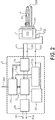
- Fig. 2 shows an embodiment of a lamp driver 3 according to the invention connected to the ignitor arrangement 1 of Fig.
- the lamp driver 3 can be connected to an external power source (not shown) by means of terminals 301, 302 and comprises the usual arrangement of functional units, namely an input circuit 30 for lamp driver protection and for filtering the higher frequencies that are generated by a DC-DC converter; a DC-DC converter 31 for converting the input voltage to a suitable level; a DC-AC converter 32 for generating a low-frequency square wave in the range of 200 - 1000 Hz; and an auxiliary ignition module 33 for applying a suitable DC voltage across the first pair of input terminals 101, 102 to the ignition arrangement 1.
- the lamp driver 3 also comprises a control circuit 34 for regulating the power applied to the lamp during steady-state operation.
- the control unit 34 is provided with an additional control input 340 to allow the lamp power to be adjusted as desired by an external module (not shown).
- an additional module 35 is realised as a temperature evaluation unit 35, whose function is to determine or estimate the temperature in the interior 100 of the ignitor housing 15. Since the spark gap is non-conductive during steady-state operation, the only current path available between the first terminal 101 and the ignition terminal 102 is through the discharge resistor.
- the ignition terminal 102 is not required during the steady-state operation of the lamp 2, so that the temperature evaluation unit 35 can incorporate the thermistor 10 into an evaluation circuit to which a known voltage is applied, and the resulting voltage can be measured between the ignition terminal 102 and another suitable node.
- the temperature evaluation unit 35 can then calculate the momentary resistance of the thermistor 10, estimate the momentary temperature T 100 in the ignitor interior 100, and provide the control unit with a value of the estimated temperature T 100 .
- Fig. 3 shows an embodiment of a temperature evaluation unit 35 for the lamp driver shown in Fig. 2 .
- the simplified diagram only indicates the relevant elements of the lamp driver 3, and only the thermistor 10 of the ignitor arrangement 1 is shown.
- a low-frequency square wave is applied across the drive terminals 101, 103 of the ignitor as shown in Fig. 1 .
- the voltage at the shared terminal 101 is essentially constant.
- the current I 10 through the thermistor 10 can be measured without interfering with the operation of the lamp.
- the temperature evaluation unit 35 makes use of the fact that a known voltage is applied to the terminals 101, 102 by the DC-AC converter 32 and the auxiliary ignition module 33.
- the temperature evaluation unit 35 comprises a current monitoring unit 350 which can measure the current I 10 through the thermistor 10.
- a memory 351 storing a look-up table relating current values to temperature values is included in the temperature evaluation unit 35. In this way, an estimated temperature value T 100 can quickly be obtained and forwarded to the control circuit of the lamp driver.
- Fig. 4 shows another embodiment of a temperature evaluation unit 35 for the lamp driver of Fig. 2 .
- the temperature evaluation unit 35 comprises a voltage monitoring unit 352 which can measure the voltage V 10 across the thermistor 10.
- a memory 351 storing a look-up table is used, in this case a look-up table relating voltage values to temperature values.
- the estimated temperature value T 100 is again forwarded to the control circuit of the lamp driver.
- Fig. 5 shows graphs of ignitor temperature (in degrees Kelvin) vs. lamp power (in Watt) for three different ambient temperatures T amb1 , T amb2 , T amb3 .
- the lowest ambient temperature T amb1 is associated with the highest maximum lamp power P max3
- the highest ambient temperature T amb3 is associated with the lowest maximum lamp power P max1 .
- the maximum ignitor temperature T max is essentially constant, since this is the temperature above which the ignitor components may suffer damage.
- a typical maximum ignitor temperature is about 150°C.
- the control unit of the lamp driver according to the invention will regulate the lamp power such that the temperature within the ignitor housing does not exceed this maximum ignitor temperature T max . Since the temperature in the ignitor housing depends to some extent on the ambient temperature, the temperature in the ignitor can be different for different ambient temperatures even if the lamp power is the same in each case.
- an exemplary power level P x is associated with three different interior ignitor temperatures T 1 , T 2 , T 3 . These different temperatures might be observed in the interior of an ignitor when used in a relatively cold environment; a 'normal' environment, and a relatively hot environment, respectively.
- the maximum power P max1 , P max2 , P max3 at which the lamp can be driven depends also on the ambient temperature T amb1 , T amb2 , T amb3 , and a lamp driver according to the invention can take this into account by regulating the lamp power in response to an estimated ignitor interior temperature as described above.
- Fig. 6 shows a prior art arrangement with an asymmetrical ignitor 60 for connecting to a lamp driver 61.
- the lamp driver 61 comprises most of the modules 30, 31, 32, 33, 34 already described above.
- a temperature sensor 603 is arranged inside the asymmetrical ignitor 60 so that it is in close proximity to the components of the ignitor 60, for example close to the conventional fixed-value discharge resistor or to the ignition capacitor.
- electrical connections 601, 602 are required.
- the driver 61 also needs corresponding connections 611, 612 so that some suitable temperature evaluation module 610 can obtain the feedback and evaluate it.
- the necessity of altering the known driver and ignitor designs to accommodate the temperature sensor 603 and the electrical connections 601, 602, 611, 612 result in an increased overall cost and a reduction in compatibility.
Landscapes
- Circuit Arrangements For Discharge Lamps (AREA)
- Lighting Device Outwards From Vehicle And Optical Signal (AREA)
Claims (15)
- Agencement d'amorceur (1) pour une lampe à décharge à haute intensité (2), lequel agencement d'amorceur (1) comprend :- une première paire de bornes d'entrée (101, 102), consistant en une borne d'amorçage (102) et une borne supplémentaire (101), pour appliquer une tension d'amorçage à l'agencement d'amorceur (1) ;- une deuxième paire de bornes d'entrée (101, 103), ne comprenant pas la borne d'amorçage (102), pour appliquer une tension de commande d'entrée à l'agencement d'amorceur (1) ;- une paire de bornes de sortie pour une connexion à la lampe à décharge à haute intensité (2) ;- un condensateur d'amorçage (11) ; et- une résistance de décharge (10) pour réaliser, après l'amorçage de la lampe à décharge à haute intensité (2), un trajet de décharge pour le condensateur d'amorçage (11) ;- le condensateur d'amorçage (11) et la résistance de décharge (10) étant connectés en parallèle l'un à l'autre entre la première paire de bornes d'entrée (101, 102),- la résistance de décharge (10) étant agencée à l'intérieur (100) d'un logement (15) de l'agencement d'amorceur (1),caractérisé en ce que- la résistance de décharge (10) est réalisée en tant que résistance dépendant de la température (10),et en ce que- une valeur de résistance de la résistance de décharge dépendant de la température (10) est associée à une température (T100) à l'intérieur (100) du logement (15) de l'agencement d'amorceur (1),- moyennant quoi l'agencement d'amorceur permet la détermination de la température (T100) à l'intérieur (100) du logement (15) de l'agencement d'amorceur (1) par la valeur de résistance de la résistance de décharge dépendant de la température (10) mesurable par l'intermédiaire de la première paire de bornes d'entrée (101, 102).
- Agencement d'amorceur (1) selon la revendication 1, dans lequel la première paire de bornes d'entrée (101, 102) et la deuxième paire de bornes d'entrée (101, 103) partagent la borne supplémentaire (101) de la première paire de bornes d'entrée (101, 102).
- Agencement d'amorceur (1) selon la revendication 1 ou 2, dans lequel la résistance de décharge dépendant de la température (10) comprend l'un quelconque : d'une thermistance à coefficient de température négatif ; d'une thermistance à coefficient de température positif; d'un silistor.
- Agencement d'amorceur (1) selon la revendication 1 ou 2, dans lequel la résistance de décharge dépendant de la température (10) est choisie sur la base d'une température à l'intérieur (100) du logement (15) de l'agencement d'amorceur (1) à une puissance de lampe nominale.
- Agencement d'amorceur (1) selon la revendication 1 ou 2, dans lequel le logement (15) est réalisé de manière à incorporer les composants électriques (10, 11, 12, 13, 14) d'un circuit d'amorceur, et dans lequel le logement (15) comprend une interface de lampe (151) pour une connexion à la lampe à décharge à haute intensité (2), et une interface de dispositif de commande (152) pour connecter les bornes d'entrée (101, 102, 103) à un dispositif de commande de lampe (3).
- Dispositif de commande de lampe (3) réalisé pour commander la lampe à décharge à haute intensité (2) par l'intermédiaire de l'agencement d'amorceur (1) de la revendication 1 ou 2, le dispositif de commande de lampe (3) comprenant :- des éléments de circuit d'amorçage (30, 31, 33) réalisés pour appliquer la tension d'amorçage entre la première paire de bornes d'entrée (101, 102) de l'agencement d'amorceur (1) ;- des éléments de circuit de commande (30, 31, 32) réalisés pour appliquer la tension de commande d'entrée entre la deuxième paire de bornes d'entrée (101, 103) de l'agencement d'amorceur (1) ;- une unité d'évaluation de température (35) réalisée pour déterminer la température (T100) à l'intérieur (100) du logement (15) de l'agencement d'amorceur (1) en mesurant la valeur de résistance de la résistance de décharge dépendant de la température (10) par l'intermédiaire de la première paire de bornes d'entrée (101, 102) ; et- une unité de commande (34) pour réguler une puissance de fonctionnement de la lampe à décharge à haute intensité (2) sur une base de la température (T100) à l'intérieur (100) du logement (15) de l'agencement d'amorceur (1).
- Dispositif de commande de lampe selon la revendication 6, dans lequel l'unité d'évaluation de température (35) est réalisée pour mesurer, par l'intermédiaire de la première paire de bornes d'entrée (101, 102), un courant (I10) à travers la résistance de décharge dépendant de la température (10) de l'agencement d'amorceur (1) et pour déterminer la température (T100) à l'intérieur (100) du logement (15) de l'agencement d'amorceur (1) sur la base du courant (I10) mesuré.
- Dispositif de commande de lampe selon la revendication 6, dans lequel l'unité d'évaluation de température (35) est réalisée pour mesurer, par l'intermédiaire de la première paire de bornes d'entrée (101, 102), une tension (V10) à travers la résistance de décharge dépendant de la température (10) de l'agencement d'amorceur (1) et pour déterminer la température (T100) à l'intérieur (100) du logement (15) de l'agencement d'amorceur (1) sur la base de la tension (V10) mesurée.
- Dispositif de commande de lampe selon la revendication 6 ou 7, dans lequel l'unité de commande (34) est réalisée pour surveiller continûment la température (T100) à l'intérieur (100) du logement (15) de l'agencement d'amorceur (1).
- Agencement d'éclairage (4) comprenant :- l'agencement d'amorceur (1) selon la revendication 1 ou 2, agencé dans le logement (15) ; et- la lampe à décharge à haute intensité (2) montée sur le logement (15).
- Procédé de commande de la lampe à décharge à haute intensité (2) par l'intermédiaire de l'agencement d'amorceur (1) de la revendication 1 ou 2, lequel procédé comprend les étapes- de connexion de la lampe à décharge à haute intensité (2) à la paire de bornes de sortie de l'agencement d'amorceur (1) ;- d'application de la tension d'amorçage entre la première paire de bornes d'entrée (101, 102) de l'agencement d'amorceur (1) afin d'amorcer la lampe à décharge à haute intensité (2) ;- d'application, après l'amorçage, de la tension de commande d'entrée entre la deuxième paire de bornes d'entrée (101, 103) de l'agencement d'amorceur (1) ;- de détermination de la température (T100) à l'intérieur (100) du logement (15) de l'agencement d'amorceur (1) en mesurant la valeur de résistance de la résistance de décharge dépendant de la température (10) par l'intermédiaire de la première paire de bornes d'entrée (101, 102) de l'agencement d'amorceur (1) ; et- de régulation d'une puissance de fonctionnement de la lampe à décharge à haute intensité (2) sur la base de la température (T100) à l'intérieur (100) du logement (15) de l'agencement d'amorceur (1).
- Procédé selon la revendication 11, comprenant une étape de mesure, par l'intermédiaire de la première paire de bornes d'entrée (101, 102), d'un courant (I10) à travers la résistance de décharge dépendant de la température (10) de l'agencement d'amorceur (1) pendant un fonctionnement en régime permanent de la lampe à décharge à haute intensité (2).
- Procédé selon la revendication 11, comprenant une étape de mesure, par l'intermédiaire de la première paire de bornes d'entrée (101, 102), d'une tension (V10) à travers la résistance de décharge dépendant de la température (10) de l'agencement d'amorceur (1) pendant un fonctionnement en régime permanent de la lampe à décharge à haute intensité (2).
- Procédé selon la revendication 11 ou 12, dans lequel la tension de commande d'entrée comprend une tension d'onde carrée basse fréquence, et l'étape de détermination de la température (T100) à l'intérieur (100) du logement (15) de l'agencement d'amorceur (1) est effectuée pendant un demi-cycle de la tension de commande d'entrée.
- Procédé selon la revendication 11 ou 12, dans lequel l'étape de régulation de la puissance de fonctionnement est effectuée de sorte que la température (T100) à l'intérieur (100) du logement (15) de l'agencement d'amorceur (1) soit maintenue au-dessous d'une limite de température supérieure (Tmax).
Applications Claiming Priority (2)
| Application Number | Priority Date | Filing Date | Title |
|---|---|---|---|
| EP14163652 | 2014-04-07 | ||
| PCT/EP2015/057453 WO2015155156A2 (fr) | 2014-04-07 | 2015-04-07 | Agencement d'allumage |
Publications (2)
| Publication Number | Publication Date |
|---|---|
| EP3130204A2 EP3130204A2 (fr) | 2017-02-15 |
| EP3130204B1 true EP3130204B1 (fr) | 2019-12-18 |
Family
ID=50434114
Family Applications (1)
| Application Number | Title | Priority Date | Filing Date |
|---|---|---|---|
| EP15713774.6A Active EP3130204B1 (fr) | 2014-04-07 | 2015-04-07 | Dispositif d'allumage pour hid lampe |
Country Status (5)
| Country | Link |
|---|---|
| US (1) | US10070506B2 (fr) |
| EP (1) | EP3130204B1 (fr) |
| JP (1) | JP6588463B2 (fr) |
| CN (1) | CN106465523B (fr) |
| WO (1) | WO2015155156A2 (fr) |
Families Citing this family (3)
| Publication number | Priority date | Publication date | Assignee | Title |
|---|---|---|---|---|
| EP3777487B1 (fr) * | 2018-05-15 | 2024-06-19 | Tridonic GmbH & Co. KG | Procédé et dispositif de détection d'état de lampe, circuit d'attaque de lampe |
| US10398004B1 (en) * | 2018-07-06 | 2019-08-27 | Elb Electronics, Inc. | LED fluorescent lamp emulator circuitry |
| US12261430B2 (en) * | 2021-12-28 | 2025-03-25 | Fuzetec Technology Co., Ltd. | Composite circuit protection device |
Family Cites Families (32)
| Publication number | Priority date | Publication date | Assignee | Title |
|---|---|---|---|---|
| US4866347A (en) * | 1987-09-28 | 1989-09-12 | Hubbell Incorporated | Compact fluorescent lamp circuit |
| US4914354A (en) * | 1988-09-08 | 1990-04-03 | General Electric Company | Reactor-type ballast circuit |
| DE4121009C2 (de) * | 1991-06-21 | 1994-01-13 | Prolux Maschinenbau Gmbh | Schaltungsanordnung zum Betrieb einer Entladungslampe |
| US5453666A (en) * | 1992-03-24 | 1995-09-26 | Philips Electronics North America Corporation | High intensity discharge lamp ballast having a transient protected power factor correction scheme |
| JPH06132087A (ja) * | 1992-10-15 | 1994-05-13 | Matsushita Electric Works Ltd | 放電灯点灯装置 |
| US5428268A (en) * | 1993-07-12 | 1995-06-27 | Led Corporation N.V. | Low frequency square wave electronic ballast for gas discharge |
| CN1056852C (zh) * | 1994-05-16 | 2000-09-27 | 华南师范大学 | 螺旋藻水溶性多糖的提取方法 |
| KR0155936B1 (ko) * | 1995-12-26 | 1998-12-15 | 손욱 | 형광 램프용 안정기 회로 |
| CA2198173A1 (fr) | 1997-02-21 | 1998-08-21 | Exacta Transformers Of Canada Ltd. | Systeme de ballast de lampe a decharge haute intensite a microcontroleur et methode associee |
| US5886481A (en) | 1997-05-15 | 1999-03-23 | Hubbell Incorporated | Reduced duty cycle high intensity discharge lamp ignitor |
| CN2317594Y (zh) | 1997-10-24 | 1999-05-05 | 洪秀治 | 荧光灯预热式电子启辉器 |
| JP2000113995A (ja) | 1998-02-25 | 2000-04-21 | Mitsubishi Electric Corp | 放電ランプ用点灯制御装置及び該装置に用いられるhブリッジ回路 |
| JP2001155888A (ja) * | 1999-11-29 | 2001-06-08 | Toshiba Lighting & Technology Corp | 高圧放電ランプ点灯装置および照明装置 |
| JP3760074B2 (ja) * | 2000-01-17 | 2006-03-29 | 株式会社小糸製作所 | 放電灯点灯回路 |
| DE10220471A1 (de) | 2002-05-07 | 2003-11-20 | Patent Treuhand Ges Fuer Elektrische Gluehlampen Mbh | Schaltungsanordnung zum Betrieb von Entladungslampen |
| US7327096B2 (en) * | 2002-06-25 | 2008-02-05 | Koninklijke Philips Electronics, N.V. | Electrode temperature differential operation of a discharge lamp |
| DE10330117A1 (de) * | 2003-07-03 | 2005-01-20 | Patent-Treuhand-Gesellschaft für elektrische Glühlampen mbH | Schaltungsanordnung zur Ansteuerung einer Hochdruckentladungslampe |
| JP2005108473A (ja) | 2003-09-29 | 2005-04-21 | Hitachi Ltd | 放電ランプ点灯装置 |
| ATE428292T1 (de) * | 2005-01-28 | 2009-04-15 | Koninkl Philips Electronics Nv | Schaltungsanordnung und verfahren zum betrieb einer hochdruck-gasentladungslampe |
| WO2006085279A1 (fr) | 2005-02-10 | 2006-08-17 | Koninklijke Philips Electronics, N.V. | Procede et systeme de commande de deconnexion d'un allumeur |
| US7333313B2 (en) * | 2005-06-15 | 2008-02-19 | Osram Sylvania Inc. | Multiplexed temperature sensing circuit for HID lamp ballast |
| CN2907170Y (zh) * | 2006-05-16 | 2007-05-30 | 彭俊忠 | 节电稳压镇流装置 |
| ATE450133T1 (de) * | 2006-02-06 | 2009-12-15 | Koninkl Philips Electronics Nv | Schaltungsanordnung und verfahren zum ansteuern einer hochdruck-gasentladungslampe |
| JP2010044980A (ja) * | 2008-08-15 | 2010-02-25 | Panasonic Electric Works Co Ltd | 放電灯点灯装置及び照明器具 |
| CN201349130Y (zh) | 2008-12-19 | 2009-11-18 | 重庆集诚汽车电子有限责任公司 | 适用于汽车电子控制系统的浪涌保护电路 |
| JP5208149B2 (ja) * | 2009-04-09 | 2013-06-12 | パナソニック株式会社 | 保護回路、及び電池パック |
| JP5280290B2 (ja) | 2009-04-24 | 2013-09-04 | 株式会社小糸製作所 | 光源点灯回路 |
| WO2010136918A1 (fr) | 2009-05-28 | 2010-12-02 | Koninklijke Philips Electronics N.V. | Jeu de conversion de luminaire |
| JP5607980B2 (ja) * | 2010-04-09 | 2014-10-15 | パナソニック株式会社 | 照明装置、ランプ、点灯回路装置、照明器具 |
| KR101181822B1 (ko) * | 2010-10-13 | 2012-09-11 | 삼성에스디아이 주식회사 | 배터리 관리 시스템 및 배터리 관리 방법, 이를 이용하는 전력 저장 장치 |
| CN103430628B (zh) * | 2011-03-10 | 2016-01-13 | 皇家飞利浦有限公司 | 一种驱动气体放电灯的方法 |
| CN104541574B (zh) * | 2012-07-20 | 2017-06-09 | 飞利浦灯具控股公司 | 用于照明控制系统中的无中性点的控制器的旁路电路 |
-
2015
- 2015-04-07 JP JP2016560926A patent/JP6588463B2/ja not_active Expired - Fee Related
- 2015-04-07 US US15/128,072 patent/US10070506B2/en not_active Expired - Fee Related
- 2015-04-07 CN CN201580017912.2A patent/CN106465523B/zh not_active Expired - Fee Related
- 2015-04-07 EP EP15713774.6A patent/EP3130204B1/fr active Active
- 2015-04-07 WO PCT/EP2015/057453 patent/WO2015155156A2/fr not_active Ceased
Non-Patent Citations (1)
| Title |
|---|
| None * |
Also Published As
| Publication number | Publication date |
|---|---|
| JP2017510957A (ja) | 2017-04-13 |
| JP6588463B2 (ja) | 2019-10-09 |
| US10070506B2 (en) | 2018-09-04 |
| CN106465523B (zh) | 2020-02-07 |
| CN106465523A (zh) | 2017-02-22 |
| US20170094758A1 (en) | 2017-03-30 |
| EP3130204A2 (fr) | 2017-02-15 |
| WO2015155156A2 (fr) | 2015-10-15 |
| WO2015155156A3 (fr) | 2015-12-10 |
Similar Documents
| Publication | Publication Date | Title |
|---|---|---|
| US11877362B2 (en) | Light emitting diode thermal foldback control device and method | |
| JP6356688B2 (ja) | レトロフィット発光ダイオード管 | |
| CN201294659Y (zh) | 用于大功率led驱动的通用温度补偿电路 | |
| JP5320076B2 (ja) | 制御ユニットに連結された温度センサを識別する方法および装置 | |
| US20080122365A1 (en) | Method of Supplying Pulsed Power to Light Bulbs in Motor Vehicles | |
| EP3130204B1 (fr) | Dispositif d'allumage pour hid lampe | |
| KR20090119981A (ko) | 예열 플러그 점화 제어 방법 및 장치 | |
| KR20090049669A (ko) | 차량용 엘이디 헤드램프 드라이버의 온도보상 회로 | |
| JP4894847B2 (ja) | ヒータ劣化検出装置およびグロープラグ通電制御装置 | |
| KR101186238B1 (ko) | 온도 보상이 가능한 글로우 플러그 제어 장치 및 그 방법 | |
| JP7419948B2 (ja) | 内燃機関の点火装置 | |
| US20080225445A1 (en) | Arc-discharge protection device with temperature detection mode | |
| US4099906A (en) | Hot surface fuel ignition system | |
| US20090184647A1 (en) | Safety starter device | |
| WO2019077740A1 (fr) | Dispositif de gestion de combustion de gaz | |
| KR20070076760A (ko) | 전원공급장치 | |
| JP5035748B2 (ja) | 高圧放電灯点灯装置及びその制御方法 | |
| JP2010123346A (ja) | 放電灯点灯装置 | |
| TW201728062A (zh) | 馬達電源電路 | |
| KR200183646Y1 (ko) | 형광등용 전자식 점등관 | |
| CN118369634A (zh) | 温度监测系统 | |
| CN121510415A (zh) | 车灯的控制系统、车辆及车灯的控制方法 | |
| KR100695729B1 (ko) | 방전 램프 제어장치 | |
| KR20160120846A (ko) | 반도체 발광소자 조명장치 | |
| JPH03276024A (ja) | 液面検出器 |
Legal Events
| Date | Code | Title | Description |
|---|---|---|---|
| STAA | Information on the status of an ep patent application or granted ep patent |
Free format text: STATUS: THE INTERNATIONAL PUBLICATION HAS BEEN MADE |
|
| PUAI | Public reference made under article 153(3) epc to a published international application that has entered the european phase |
Free format text: ORIGINAL CODE: 0009012 |
|
| STAA | Information on the status of an ep patent application or granted ep patent |
Free format text: STATUS: REQUEST FOR EXAMINATION WAS MADE |
|
| 17P | Request for examination filed |
Effective date: 20161107 |
|
| AK | Designated contracting states |
Kind code of ref document: A2 Designated state(s): AL AT BE BG CH CY CZ DE DK EE ES FI FR GB GR HR HU IE IS IT LI LT LU LV MC MK MT NL NO PL PT RO RS SE SI SK SM TR |
|
| AX | Request for extension of the european patent |
Extension state: BA ME |
|
| DAV | Request for validation of the european patent (deleted) | ||
| DAX | Request for extension of the european patent (deleted) | ||
| RAP1 | Party data changed (applicant data changed or rights of an application transferred) |
Owner name: LUMILEDS HOLDING B.V. |
|
| STAA | Information on the status of an ep patent application or granted ep patent |
Free format text: STATUS: EXAMINATION IS IN PROGRESS |
|
| 17Q | First examination report despatched |
Effective date: 20181204 |
|
| RAP1 | Party data changed (applicant data changed or rights of an application transferred) |
Owner name: LUMILEDS HOLDING B.V. |
|
| GRAP | Despatch of communication of intention to grant a patent |
Free format text: ORIGINAL CODE: EPIDOSNIGR1 |
|
| STAA | Information on the status of an ep patent application or granted ep patent |
Free format text: STATUS: GRANT OF PATENT IS INTENDED |
|
| INTG | Intention to grant announced |
Effective date: 20190806 |
|
| GRAS | Grant fee paid |
Free format text: ORIGINAL CODE: EPIDOSNIGR3 |
|
| GRAA | (expected) grant |
Free format text: ORIGINAL CODE: 0009210 |
|
| STAA | Information on the status of an ep patent application or granted ep patent |
Free format text: STATUS: THE PATENT HAS BEEN GRANTED |
|
| AK | Designated contracting states |
Kind code of ref document: B1 Designated state(s): AL AT BE BG CH CY CZ DE DK EE ES FI FR GB GR HR HU IE IS IT LI LT LU LV MC MK MT NL NO PL PT RO RS SE SI SK SM TR |
|
| REG | Reference to a national code |
Ref country code: CH Ref legal event code: EP |
|
| REG | Reference to a national code |
Ref country code: IE Ref legal event code: FG4D |
|
| REG | Reference to a national code |
Ref country code: DE Ref legal event code: R096 Ref document number: 602015043824 Country of ref document: DE |
|
| REG | Reference to a national code |
Ref country code: AT Ref legal event code: REF Ref document number: 1216056 Country of ref document: AT Kind code of ref document: T Effective date: 20200115 |
|
| REG | Reference to a national code |
Ref country code: NL Ref legal event code: MP Effective date: 20191218 |
|
| PG25 | Lapsed in a contracting state [announced via postgrant information from national office to epo] |
Ref country code: LV Free format text: LAPSE BECAUSE OF FAILURE TO SUBMIT A TRANSLATION OF THE DESCRIPTION OR TO PAY THE FEE WITHIN THE PRESCRIBED TIME-LIMIT Effective date: 20191218 Ref country code: SE Free format text: LAPSE BECAUSE OF FAILURE TO SUBMIT A TRANSLATION OF THE DESCRIPTION OR TO PAY THE FEE WITHIN THE PRESCRIBED TIME-LIMIT Effective date: 20191218 Ref country code: LT Free format text: LAPSE BECAUSE OF FAILURE TO SUBMIT A TRANSLATION OF THE DESCRIPTION OR TO PAY THE FEE WITHIN THE PRESCRIBED TIME-LIMIT Effective date: 20191218 Ref country code: BG Free format text: LAPSE BECAUSE OF FAILURE TO SUBMIT A TRANSLATION OF THE DESCRIPTION OR TO PAY THE FEE WITHIN THE PRESCRIBED TIME-LIMIT Effective date: 20200318 Ref country code: FI Free format text: LAPSE BECAUSE OF FAILURE TO SUBMIT A TRANSLATION OF THE DESCRIPTION OR TO PAY THE FEE WITHIN THE PRESCRIBED TIME-LIMIT Effective date: 20191218 Ref country code: GR Free format text: LAPSE BECAUSE OF FAILURE TO SUBMIT A TRANSLATION OF THE DESCRIPTION OR TO PAY THE FEE WITHIN THE PRESCRIBED TIME-LIMIT Effective date: 20200319 Ref country code: NO Free format text: LAPSE BECAUSE OF FAILURE TO SUBMIT A TRANSLATION OF THE DESCRIPTION OR TO PAY THE FEE WITHIN THE PRESCRIBED TIME-LIMIT Effective date: 20200318 |
|
| REG | Reference to a national code |
Ref country code: LT Ref legal event code: MG4D |
|
| PG25 | Lapsed in a contracting state [announced via postgrant information from national office to epo] |
Ref country code: RS Free format text: LAPSE BECAUSE OF FAILURE TO SUBMIT A TRANSLATION OF THE DESCRIPTION OR TO PAY THE FEE WITHIN THE PRESCRIBED TIME-LIMIT Effective date: 20191218 Ref country code: HR Free format text: LAPSE BECAUSE OF FAILURE TO SUBMIT A TRANSLATION OF THE DESCRIPTION OR TO PAY THE FEE WITHIN THE PRESCRIBED TIME-LIMIT Effective date: 20191218 |
|
| PG25 | Lapsed in a contracting state [announced via postgrant information from national office to epo] |
Ref country code: AL Free format text: LAPSE BECAUSE OF FAILURE TO SUBMIT A TRANSLATION OF THE DESCRIPTION OR TO PAY THE FEE WITHIN THE PRESCRIBED TIME-LIMIT Effective date: 20191218 |
|
| PG25 | Lapsed in a contracting state [announced via postgrant information from national office to epo] |
Ref country code: CZ Free format text: LAPSE BECAUSE OF FAILURE TO SUBMIT A TRANSLATION OF THE DESCRIPTION OR TO PAY THE FEE WITHIN THE PRESCRIBED TIME-LIMIT Effective date: 20191218 Ref country code: PT Free format text: LAPSE BECAUSE OF FAILURE TO SUBMIT A TRANSLATION OF THE DESCRIPTION OR TO PAY THE FEE WITHIN THE PRESCRIBED TIME-LIMIT Effective date: 20200513 Ref country code: RO Free format text: LAPSE BECAUSE OF FAILURE TO SUBMIT A TRANSLATION OF THE DESCRIPTION OR TO PAY THE FEE WITHIN THE PRESCRIBED TIME-LIMIT Effective date: 20191218 Ref country code: NL Free format text: LAPSE BECAUSE OF FAILURE TO SUBMIT A TRANSLATION OF THE DESCRIPTION OR TO PAY THE FEE WITHIN THE PRESCRIBED TIME-LIMIT Effective date: 20191218 Ref country code: EE Free format text: LAPSE BECAUSE OF FAILURE TO SUBMIT A TRANSLATION OF THE DESCRIPTION OR TO PAY THE FEE WITHIN THE PRESCRIBED TIME-LIMIT Effective date: 20191218 |
|
| PG25 | Lapsed in a contracting state [announced via postgrant information from national office to epo] |
Ref country code: SK Free format text: LAPSE BECAUSE OF FAILURE TO SUBMIT A TRANSLATION OF THE DESCRIPTION OR TO PAY THE FEE WITHIN THE PRESCRIBED TIME-LIMIT Effective date: 20191218 Ref country code: IS Free format text: LAPSE BECAUSE OF FAILURE TO SUBMIT A TRANSLATION OF THE DESCRIPTION OR TO PAY THE FEE WITHIN THE PRESCRIBED TIME-LIMIT Effective date: 20200418 Ref country code: SM Free format text: LAPSE BECAUSE OF FAILURE TO SUBMIT A TRANSLATION OF THE DESCRIPTION OR TO PAY THE FEE WITHIN THE PRESCRIBED TIME-LIMIT Effective date: 20191218 |
|
| REG | Reference to a national code |
Ref country code: DE Ref legal event code: R097 Ref document number: 602015043824 Country of ref document: DE |
|
| REG | Reference to a national code |
Ref country code: AT Ref legal event code: MK05 Ref document number: 1216056 Country of ref document: AT Kind code of ref document: T Effective date: 20191218 |
|
| PLBE | No opposition filed within time limit |
Free format text: ORIGINAL CODE: 0009261 |
|
| STAA | Information on the status of an ep patent application or granted ep patent |
Free format text: STATUS: NO OPPOSITION FILED WITHIN TIME LIMIT |
|
| PG25 | Lapsed in a contracting state [announced via postgrant information from national office to epo] |
Ref country code: ES Free format text: LAPSE BECAUSE OF FAILURE TO SUBMIT A TRANSLATION OF THE DESCRIPTION OR TO PAY THE FEE WITHIN THE PRESCRIBED TIME-LIMIT Effective date: 20191218 Ref country code: DK Free format text: LAPSE BECAUSE OF FAILURE TO SUBMIT A TRANSLATION OF THE DESCRIPTION OR TO PAY THE FEE WITHIN THE PRESCRIBED TIME-LIMIT Effective date: 20191218 |
|
| 26N | No opposition filed |
Effective date: 20200921 |
|
| PG25 | Lapsed in a contracting state [announced via postgrant information from national office to epo] |
Ref country code: MC Free format text: LAPSE BECAUSE OF FAILURE TO SUBMIT A TRANSLATION OF THE DESCRIPTION OR TO PAY THE FEE WITHIN THE PRESCRIBED TIME-LIMIT Effective date: 20191218 Ref country code: AT Free format text: LAPSE BECAUSE OF FAILURE TO SUBMIT A TRANSLATION OF THE DESCRIPTION OR TO PAY THE FEE WITHIN THE PRESCRIBED TIME-LIMIT Effective date: 20191218 Ref country code: SI Free format text: LAPSE BECAUSE OF FAILURE TO SUBMIT A TRANSLATION OF THE DESCRIPTION OR TO PAY THE FEE WITHIN THE PRESCRIBED TIME-LIMIT Effective date: 20191218 |
|
| REG | Reference to a national code |
Ref country code: CH Ref legal event code: PL |
|
| PG25 | Lapsed in a contracting state [announced via postgrant information from national office to epo] |
Ref country code: IT Free format text: LAPSE BECAUSE OF FAILURE TO SUBMIT A TRANSLATION OF THE DESCRIPTION OR TO PAY THE FEE WITHIN THE PRESCRIBED TIME-LIMIT Effective date: 20191218 Ref country code: LI Free format text: LAPSE BECAUSE OF NON-PAYMENT OF DUE FEES Effective date: 20200430 Ref country code: CH Free format text: LAPSE BECAUSE OF NON-PAYMENT OF DUE FEES Effective date: 20200430 Ref country code: LU Free format text: LAPSE BECAUSE OF NON-PAYMENT OF DUE FEES Effective date: 20200407 |
|
| REG | Reference to a national code |
Ref country code: BE Ref legal event code: MM Effective date: 20200430 |
|
| PG25 | Lapsed in a contracting state [announced via postgrant information from national office to epo] |
Ref country code: BE Free format text: LAPSE BECAUSE OF NON-PAYMENT OF DUE FEES Effective date: 20200430 Ref country code: PL Free format text: LAPSE BECAUSE OF FAILURE TO SUBMIT A TRANSLATION OF THE DESCRIPTION OR TO PAY THE FEE WITHIN THE PRESCRIBED TIME-LIMIT Effective date: 20191218 |
|
| PG25 | Lapsed in a contracting state [announced via postgrant information from national office to epo] |
Ref country code: IE Free format text: LAPSE BECAUSE OF NON-PAYMENT OF DUE FEES Effective date: 20200407 |
|
| PGFP | Annual fee paid to national office [announced via postgrant information from national office to epo] |
Ref country code: DE Payment date: 20210428 Year of fee payment: 7 Ref country code: FR Payment date: 20210427 Year of fee payment: 7 |
|
| PGFP | Annual fee paid to national office [announced via postgrant information from national office to epo] |
Ref country code: GB Payment date: 20210426 Year of fee payment: 7 |
|
| PG25 | Lapsed in a contracting state [announced via postgrant information from national office to epo] |
Ref country code: TR Free format text: LAPSE BECAUSE OF FAILURE TO SUBMIT A TRANSLATION OF THE DESCRIPTION OR TO PAY THE FEE WITHIN THE PRESCRIBED TIME-LIMIT Effective date: 20191218 Ref country code: MT Free format text: LAPSE BECAUSE OF FAILURE TO SUBMIT A TRANSLATION OF THE DESCRIPTION OR TO PAY THE FEE WITHIN THE PRESCRIBED TIME-LIMIT Effective date: 20191218 Ref country code: CY Free format text: LAPSE BECAUSE OF FAILURE TO SUBMIT A TRANSLATION OF THE DESCRIPTION OR TO PAY THE FEE WITHIN THE PRESCRIBED TIME-LIMIT Effective date: 20191218 |
|
| PG25 | Lapsed in a contracting state [announced via postgrant information from national office to epo] |
Ref country code: MK Free format text: LAPSE BECAUSE OF FAILURE TO SUBMIT A TRANSLATION OF THE DESCRIPTION OR TO PAY THE FEE WITHIN THE PRESCRIBED TIME-LIMIT Effective date: 20191218 |
|
| REG | Reference to a national code |
Ref country code: DE Ref legal event code: R119 Ref document number: 602015043824 Country of ref document: DE |
|
| GBPC | Gb: european patent ceased through non-payment of renewal fee |
Effective date: 20220407 |
|
| PG25 | Lapsed in a contracting state [announced via postgrant information from national office to epo] |
Ref country code: GB Free format text: LAPSE BECAUSE OF NON-PAYMENT OF DUE FEES Effective date: 20220407 Ref country code: FR Free format text: LAPSE BECAUSE OF NON-PAYMENT OF DUE FEES Effective date: 20220430 Ref country code: DE Free format text: LAPSE BECAUSE OF NON-PAYMENT OF DUE FEES Effective date: 20221103 |