EP3130445B1 - Rouleau de façonnage pour moulage par extrusion à l'état fondu, ensemble rouleau de façonnage pour moulage par extrusion à l'état fondu, et procédé de moulage par extrusion à l'état fondu - Google Patents
Rouleau de façonnage pour moulage par extrusion à l'état fondu, ensemble rouleau de façonnage pour moulage par extrusion à l'état fondu, et procédé de moulage par extrusion à l'état fondu Download PDFInfo
- Publication number
- EP3130445B1 EP3130445B1 EP14888676.5A EP14888676A EP3130445B1 EP 3130445 B1 EP3130445 B1 EP 3130445B1 EP 14888676 A EP14888676 A EP 14888676A EP 3130445 B1 EP3130445 B1 EP 3130445B1
- Authority
- EP
- European Patent Office
- Prior art keywords
- roll
- extrusion molding
- melt extrusion
- cylinder
- body part
- Prior art date
- Legal status (The legal status is an assumption and is not a legal conclusion. Google has not performed a legal analysis and makes no representation as to the accuracy of the status listed.)
- Active
Links
Images



Classifications
-
- B—PERFORMING OPERATIONS; TRANSPORTING
- B29—WORKING OF PLASTICS; WORKING OF SUBSTANCES IN A PLASTIC STATE IN GENERAL
- B29C—SHAPING OR JOINING OF PLASTICS; SHAPING OF MATERIAL IN A PLASTIC STATE, NOT OTHERWISE PROVIDED FOR; AFTER-TREATMENT OF THE SHAPED PRODUCTS, e.g. REPAIRING
- B29C48/00—Extrusion moulding, i.e. expressing the moulding material through a die or nozzle which imparts the desired form; Apparatus therefor
- B29C48/25—Component parts, details or accessories; Auxiliary operations
- B29C48/88—Thermal treatment of the stream of extruded material, e.g. cooling
- B29C48/918—Thermal treatment of the stream of extruded material, e.g. cooling characterized by differential heating or cooling
-
- B—PERFORMING OPERATIONS; TRANSPORTING
- B29—WORKING OF PLASTICS; WORKING OF SUBSTANCES IN A PLASTIC STATE IN GENERAL
- B29C—SHAPING OR JOINING OF PLASTICS; SHAPING OF MATERIAL IN A PLASTIC STATE, NOT OTHERWISE PROVIDED FOR; AFTER-TREATMENT OF THE SHAPED PRODUCTS, e.g. REPAIRING
- B29C48/00—Extrusion moulding, i.e. expressing the moulding material through a die or nozzle which imparts the desired form; Apparatus therefor
- B29C48/001—Combinations of extrusion moulding with other shaping operations
- B29C48/002—Combinations of extrusion moulding with other shaping operations combined with surface shaping
-
- B—PERFORMING OPERATIONS; TRANSPORTING
- B29—WORKING OF PLASTICS; WORKING OF SUBSTANCES IN A PLASTIC STATE IN GENERAL
- B29C—SHAPING OR JOINING OF PLASTICS; SHAPING OF MATERIAL IN A PLASTIC STATE, NOT OTHERWISE PROVIDED FOR; AFTER-TREATMENT OF THE SHAPED PRODUCTS, e.g. REPAIRING
- B29C33/00—Moulds or cores; Details thereof or accessories therefor
- B29C33/38—Moulds or cores; Details thereof or accessories therefor characterised by the material or the manufacturing process
- B29C33/3828—Moulds made of at least two different materials having different thermal conductivities
-
- B—PERFORMING OPERATIONS; TRANSPORTING
- B29—WORKING OF PLASTICS; WORKING OF SUBSTANCES IN A PLASTIC STATE IN GENERAL
- B29C—SHAPING OR JOINING OF PLASTICS; SHAPING OF MATERIAL IN A PLASTIC STATE, NOT OTHERWISE PROVIDED FOR; AFTER-TREATMENT OF THE SHAPED PRODUCTS, e.g. REPAIRING
- B29C43/00—Compression moulding, i.e. applying external pressure to flow the moulding material; Apparatus therefor
- B29C43/32—Component parts, details or accessories; Auxiliary operations
- B29C43/44—Compression means for making articles of indefinite length
- B29C43/46—Rollers
-
- B—PERFORMING OPERATIONS; TRANSPORTING
- B29—WORKING OF PLASTICS; WORKING OF SUBSTANCES IN A PLASTIC STATE IN GENERAL
- B29C—SHAPING OR JOINING OF PLASTICS; SHAPING OF MATERIAL IN A PLASTIC STATE, NOT OTHERWISE PROVIDED FOR; AFTER-TREATMENT OF THE SHAPED PRODUCTS, e.g. REPAIRING
- B29C48/00—Extrusion moulding, i.e. expressing the moulding material through a die or nozzle which imparts the desired form; Apparatus therefor
- B29C48/001—Combinations of extrusion moulding with other shaping operations
- B29C48/0011—Combinations of extrusion moulding with other shaping operations combined with compression moulding
-
- B—PERFORMING OPERATIONS; TRANSPORTING
- B29—WORKING OF PLASTICS; WORKING OF SUBSTANCES IN A PLASTIC STATE IN GENERAL
- B29C—SHAPING OR JOINING OF PLASTICS; SHAPING OF MATERIAL IN A PLASTIC STATE, NOT OTHERWISE PROVIDED FOR; AFTER-TREATMENT OF THE SHAPED PRODUCTS, e.g. REPAIRING
- B29C48/00—Extrusion moulding, i.e. expressing the moulding material through a die or nozzle which imparts the desired form; Apparatus therefor
- B29C48/03—Extrusion moulding, i.e. expressing the moulding material through a die or nozzle which imparts the desired form; Apparatus therefor characterised by the shape of the extruded material at extrusion
- B29C48/07—Flat, e.g. panels
- B29C48/08—Flat, e.g. panels flexible, e.g. films
-
- B—PERFORMING OPERATIONS; TRANSPORTING
- B29—WORKING OF PLASTICS; WORKING OF SUBSTANCES IN A PLASTIC STATE IN GENERAL
- B29C—SHAPING OR JOINING OF PLASTICS; SHAPING OF MATERIAL IN A PLASTIC STATE, NOT OTHERWISE PROVIDED FOR; AFTER-TREATMENT OF THE SHAPED PRODUCTS, e.g. REPAIRING
- B29C48/00—Extrusion moulding, i.e. expressing the moulding material through a die or nozzle which imparts the desired form; Apparatus therefor
- B29C48/25—Component parts, details or accessories; Auxiliary operations
- B29C48/88—Thermal treatment of the stream of extruded material, e.g. cooling
- B29C48/90—Thermal treatment of the stream of extruded material, e.g. cooling with calibration or sizing, i.e. combined with fixing or setting of the final dimensions of the extruded article
-
- B—PERFORMING OPERATIONS; TRANSPORTING
- B29—WORKING OF PLASTICS; WORKING OF SUBSTANCES IN A PLASTIC STATE IN GENERAL
- B29C—SHAPING OR JOINING OF PLASTICS; SHAPING OF MATERIAL IN A PLASTIC STATE, NOT OTHERWISE PROVIDED FOR; AFTER-TREATMENT OF THE SHAPED PRODUCTS, e.g. REPAIRING
- B29C59/00—Surface shaping of articles, e.g. embossing; Apparatus therefor
- B29C59/02—Surface shaping of articles, e.g. embossing; Apparatus therefor by mechanical means, e.g. pressing
- B29C59/04—Surface shaping of articles, e.g. embossing; Apparatus therefor by mechanical means, e.g. pressing using rollers or endless belts
-
- B—PERFORMING OPERATIONS; TRANSPORTING
- B29—WORKING OF PLASTICS; WORKING OF SUBSTANCES IN A PLASTIC STATE IN GENERAL
- B29C—SHAPING OR JOINING OF PLASTICS; SHAPING OF MATERIAL IN A PLASTIC STATE, NOT OTHERWISE PROVIDED FOR; AFTER-TREATMENT OF THE SHAPED PRODUCTS, e.g. REPAIRING
- B29C48/00—Extrusion moulding, i.e. expressing the moulding material through a die or nozzle which imparts the desired form; Apparatus therefor
- B29C48/25—Component parts, details or accessories; Auxiliary operations
- B29C48/88—Thermal treatment of the stream of extruded material, e.g. cooling
- B29C48/90—Thermal treatment of the stream of extruded material, e.g. cooling with calibration or sizing, i.e. combined with fixing or setting of the final dimensions of the extruded article
- B29C48/906—Thermal treatment of the stream of extruded material, e.g. cooling with calibration or sizing, i.e. combined with fixing or setting of the final dimensions of the extruded article using roller calibration
-
- B—PERFORMING OPERATIONS; TRANSPORTING
- B29—WORKING OF PLASTICS; WORKING OF SUBSTANCES IN A PLASTIC STATE IN GENERAL
- B29C—SHAPING OR JOINING OF PLASTICS; SHAPING OF MATERIAL IN A PLASTIC STATE, NOT OTHERWISE PROVIDED FOR; AFTER-TREATMENT OF THE SHAPED PRODUCTS, e.g. REPAIRING
- B29C48/00—Extrusion moulding, i.e. expressing the moulding material through a die or nozzle which imparts the desired form; Apparatus therefor
- B29C48/25—Component parts, details or accessories; Auxiliary operations
- B29C48/88—Thermal treatment of the stream of extruded material, e.g. cooling
- B29C48/911—Cooling
- B29C48/9135—Cooling of flat articles, e.g. using specially adapted supporting means
- B29C48/914—Cooling drums
-
- B—PERFORMING OPERATIONS; TRANSPORTING
- B29—WORKING OF PLASTICS; WORKING OF SUBSTANCES IN A PLASTIC STATE IN GENERAL
- B29K—INDEXING SCHEME ASSOCIATED WITH SUBCLASSES B29B, B29C OR B29D, RELATING TO MOULDING MATERIALS OR TO MATERIALS FOR MOULDS, REINFORCEMENTS, FILLERS OR PREFORMED PARTS, e.g. INSERTS
- B29K2995/00—Properties of moulding materials, reinforcements, fillers, preformed parts or moulds
- B29K2995/0012—Properties of moulding materials, reinforcements, fillers, preformed parts or moulds having particular thermal properties
- B29K2995/0013—Conductive
-
- B—PERFORMING OPERATIONS; TRANSPORTING
- B29—WORKING OF PLASTICS; WORKING OF SUBSTANCES IN A PLASTIC STATE IN GENERAL
- B29L—INDEXING SCHEME ASSOCIATED WITH SUBCLASS B29C, RELATING TO PARTICULAR ARTICLES
- B29L2031/00—Other particular articles
- B29L2031/32—Wheels, pinions, pulleys, castors or rollers, Rims
- B29L2031/324—Rollers or cylinders having an axial length of several times the diameter, e.g. embossing, pressing or printing
Definitions
- the present invention relates to a shaping roll for melt extrusion molding, a shaping roll assembly for melt extrusion molding, and a melt extrusion molding method.
- a shaping roll for melt extrusion molding that has a fine structure on its surface is used to transfer the fine structure to the surface of the sheet, so that various functions are given to the surface of a sheet molded article formed of thermoplastic resin.
- a sheet molded article of thermoplastic resin having a fine structure on its surface is formed using melt extrusion molding, the transfer uniformity in the width direction, especially the transfer uniformity in the end part of the sheet molded article, is a major problem.
- a sheet (often referred to below as a "sheet") of molten thermoplastic resin having flowed from the lip part of a T-die or coat hanger die is cooled by air in an air gap and the sheet temperature is significantly reduced before being pressed between a metal shaping roll (often referred to below as a "first roll”) for melt extrusion molding and a pressing roll (often referred to below as a "second roll”). Since the degree of reduction of the temperature significantly differs between the sheet middle part and the sheet end part and the part of the sheet closer to the sheet end part is easily cooled, reduction of the temperature is larger in the part closer to the sheet end part.
- the transfer state of the fine structure of the surface of the first roll differs between the sheet middle part and the sheet end part, thereby producing non-uniformity in physical properties (for example, birefringence and thickness) between the sheet middle part and the sheet end part.
- temperature changes along the axial line of the first roll of the sheet in contact with the first roll are made different.
- the first roll internally has a heat medium passage for controlling the surface temperature of the first roll.
- the temperature changes of the sheet in contact with the first roll is larger than in the case in which the distance from the heat medium passage to the surface of the first roll is long.
- the temperature changes of the part of the sheet in contact with the end part of the first roll can be made smaller than the temperature changes of the part of the sheet in contact with the middle part of the first roll.
- the transfer state and physical properties of the fine structure of the surface of the first roll can be made uniform between the sheet middle part and the sheet end part.
- the structure disclosed in Figs. 11 and 12 of Japanese Unexamined Utility Model Application Publication No. 1994-001834 can reduce the distance from the heat medium passage to the surface of the first roll in the middle part of the first roll and increase the distance from the heat medium passage to the surface of the first roll in the end part of the first roll.
- the structure disclosed in Figs. 11 and 12 in Japanese Unexamined Utility Model Application Publication No. 1994-001834 is achieved by a so-called drilled roll created by opening a circular hole for a heat medium passage from the end surface of the first roll using a cutting drill.
- a so-called drilled roll created by opening a circular hole for a heat medium passage from the end surface of the first roll using a cutting drill.
- an object of the invention is to provide a shaping roll for melt extrusion molding that molds a sheet molded article (film molded article) minimizing the differences in physical properties between the middle part and the end part using a melt extrusion molding method, a shaping roll assembly for melt extrusion molding having such a shaping roll for melt extrusion molding, and a melt extrusion molding method using such a shaping roll assembly for melt extrusion molding.
- the first disclosure of the present application relates to a shaping roll for melt extrusion molding used for melt extrusion molding of thermoplastic resin
- a shaping roll for melt extrusion molding used for melt extrusion molding of thermoplastic resin
- the first cylinder comprises a first metal material having a thermal conductivity of 40 W/m ⁇ K or more
- the second cylinder comprises a second metal material having a thermal conductivity of 20 W/m ⁇ K or less
- the first cylinder and the second cylinder are at least partially joined to each other.
- the second disclosure of the present application which corresponds to the present invention, relates to a shaping roll for melt extrusion molding used for melt extrusion molding of thermoplastic resin
- a shaping roll for melt extrusion molding used for melt extrusion molding of thermoplastic resin
- the roll body part comprises a first metal material having a thermal conductivity of 40 W/m ⁇ K or more
- the cylindrical member comprises a second metal material having a thermal conductivity of 20 W/m ⁇ K or less
- the cylindrical members are at least partially joined to the cutouts of the roll body part.
- the upper limit value of the thermal conductivity of the first metal material may be 100 W/m ⁇ K and the lower limit value of the thermal conductivity of the second metal material may be 5 W/m ⁇ K, although the invention is not limited to these values.
- a shaping roll assembly for melt extrusion molding according to the first disclosure or the second disclosure comprises a shaping roll (often referred to below as “first roll” for convenience) for melt extrusion molding and a pressure roll (often referred to below as “second roll” for convenience) disposed facing the shaping roll for melt extrusion molding, in which the shaping roll (first roll) for melt extrusion molding comprises the shaping roll for melt extrusion molding according to the first disclosure or the second disclosure.
- a melt extrusion molding method uses a shaping roll assembly for melt extrusion molding including a shaping roll (first roll) for melt extrusion molding and a pressure roll (second roll) disposed facing the shaping roll for melt extrusion molding, the shaping roll (first roll) for melt extrusion molding including the shaping roll for melt extrusion molding according to the first disclosure or the second disclosure, in which molten thermoplastic resin pushed out of a die is passed through a gap between the shaping roll (first roll) for melt extrusion molding and the pressure roll (second roll) to obtain a sheet molded article.
- the sheet molded article comprises a sheet, a film, or a film molded article.
- the shaping roll for melt extrusion molding included in the shaping roll assembly for melt extrusion molding according to the first disclosure, or the shaping roll for melt extrusion molding used for the melt extrusion molding method according to the first disclosure (these shaping rolls for melt extrusion molding may be collectively referred to below as "first roll and the like according to the first disclosure")
- the second cylinder may cover the surfaces of the both end portions of the roll body part with an extension part of the first cylinder.
- the surfaces of the second cylinder may be covered with the extension part of the first cylinder.
- the second cylinder and the extension part of the first cylinder may be integrally screwed with each other, the second cylinder and the extension part of the first cylinder may be integrally shrink-fitted to each other, or the second cylinder and the extension part of the first cylinder may be integrally welded to each other.
- the ratio of the wall thickness of the second cylinder to the wall thickness of the extension part of the first cylinder may be 1/9 to 9/1, for example.
- the total wall thickness of the second cylinder and the extension part of the first cylinder may be 1 mm to 10 mm, for example.
- the extension part of the first cylinder is desirably disposed externally.
- the second cylinder is desirably disposed externally. Such selection can be performed as appropriate depending on the differences in the specification and requirement of the first roll and the like according to the first disclosure.
- a plating layer may be formed at least on the surface of the first cylinder. That is, a plating layer may be formed on the surface of the first cylinder or plating layers may be formed on the surfaces of the first cylinder and the second cylinder.
- the shaping roll for melt extrusion molding included in the shaping roll assembly for melt extrusion molding according to the second disclosure, or the shaping roll for melt extrusion molding used for the melt extrusion molding method according to the second disclosure may be collectively referred to below as "first roll and the like according to the second disclosure"
- plating layers may be formed on the surfaces of the roll body part and the cylindrical member.
- the plating layer is preferably at least one plating layer selected from a group including, for example, a copper plating layer, a nickel plating layer, an electroless nickel-phosphorus plating layer, an electrolytic nickel-phosphorus plating layer, and a chrome plating layer.
- a first roll having a fine convexo-concave structure on its surface is formed, it is preferable to configure a plating layer using copper or nickel having low Vickers hardness and good machinability.
- a plating layer when high Vickers hardness is required, it is preferable to configure a plating layer using chrome. In addition, when moderately high Vickers hardness and micro-machinability are both required, it is preferable to configure a plating layer using nickel-phosphorus alloy.
- the thickness of a plating layer is 0.05 mm to 2.0 mm, for example.
- a mat pattern, a prism pattern, or a micro lens array pattern may be formed on the surface of the plating layer.
- a mat pattern can be formed using sand blast, electric discharge machining, chemical etching, or other methods.
- a prism pattern or a micro lens array pattern can be formed by cutting or the like using a diamond cutting tool.
- an ornamental design for exterior material or the like can also be formed.
- the formation of a plating layer or the machining of an optical pattern on the surfaces (such as the first roll according to the first disclosure) of the first cylinder and the second cylinder or on the surfaces of the roll body part and the cylindrical member (such as the first roll according to the second disclosure) may be performed before the first cylinder and the second cylinder are attached to the roll body part, before the cylindrical member are attached to the roll body part, or after the cylindrical member are attached to the roll body part.
- the formation or the machining is desirably performed after the first cylinder and the second cylinder are attached to the roll body part or after the cylindrical member are attached to the roll body part.
- the first roll may be used as a mirror surface roll. That is, the surface of a plating layer may be a mirror surface.
- hard chrome layers are preferably formed on the surfaces of the first cylinder and the second cylinder using a plating method (for example, the first roll and the like according to the first disclosure) or hard chrome layers are preferably formed on the surfaces of the roll body part and the cylindrical member using a plating method (for example, the first roll and the like according to the second disclosure).
- a hard chrome layer is very hard, has good polishing performance, and does not easily get scratched.
- the surface roughness of a hard chrome layer preferably has a surface roughness of at least 0.2S or less (arithmetic average surface roughness of 50 nm or less).
- the polished surface is transferred when the first roll is used as a mirror surface roll, a plane sheet molded article can be made very flat. That is, the mirror surface transfer property of the sheet end part is improved and a thick part caused by the neck-in of the sheet end part is easily crushed, so the uniform press work of the entire surface can be performed and the surface accuracy is further improved as compared with the case in which a normal mirror surface roll is used.
- molten thermoplastic resin flowing from the lip part of a die necks in at an air gap immediately before contact with the shaping roll for melt extrusion molding and the endmost part of a sheet molded article may become too thick to make control by adjustment of the lip opening.
- the thick part of the endmost part of a sheet molded article is not preferable because it may become a transfer inhibition factor.
- a step may be formed in the roll end part so that the thick part of the endmost part does not undergo press work in a conventional art, such a step does not need to be provided in the roll end part in the first roll and the like according to the first disclosure or the second disclosure.
- the first cylinder and the second cylinder are shrink-fitted to the roll body part and, when the inner diameter of the first cylinder and the second cylinder at normal temperatures is D 2-i and the outer diameter of the roll body part at normal temperatures is D 1-o , the following expression is preferably met. 0 mm ⁇ D 1-o - D 2-i ⁇ 0.4 mm More preferably, the following expression is met.
- the outer diameter D 1-o of the roll body part may be 200 mm to 800 mm and the wall thickness of the first cylinder and the second cylinder may be 1 mm to 10 mm, for example.
- the wall thickness of the first cylinder and the second cylinder is represented by the following expression when the outer diameter of the first cylinder and the second cylinder is D 2-o at normal temperatures.
- the degree of the cooling delay effect of molten thermoplastic resin in contact with the first roll by the first cylinder and the second cylinder can be controlled.
- the linear expansion coefficients of the first cylinder and the second cylinder are preferably smaller than the linear expansion coefficient of the roll body part. This is because the first cylinder and the second cylinder are prevented from being loosened due to an increase in the temperature of the first roll when the first roll needs to be set to a predetermined set temperature during melt extrusion molding.
- the linear expansion coefficients of the first cylinder and the second cylinder are larger than or substantially equal to the linear expansion coefficient of the roll body part, it is possible to prevent the first cylinder and the second cylinder from being loosened by making the shrink-fitting margin slightly larger and prevent the first cylinder and the second cylinder from rotating idle or being removed by spot-welding the ends of the first cylinder and the second cylinder to the roll body part.
- the cylindrical member is shrink-fitted to the roll body part and, when the inner diameter of the cylindrical member at normal temperatures is D 2-i and the outer diameter in the cutout of the roll body part at normal temperatures is D 1-o , the following expression is preferably met. 0 mm ⁇ D 1-o - D 2-i ⁇ 0.4 mm More preferably, the following expression is met. 0.05 mm ⁇ D 1-o - D 2-i ⁇ 0.20 mm
- the outer diameter D 1-o of the roll body part may be 200 mm to 800 mm and the wall thickness of the cylindrical member is 1 mm to 10 mm, for example.
- the wall thickness of the cylindrical member is represented by the following expression when the outer diameter of the cylindrical member at normal temperatures is D 2-o . (D 2-o - D 2-i )/2
- the degree of the cooling delay effect of molten thermoplastic resin in contact with the first roll can be controlled by the roll body part and the cylindrical member. This is because the cylindrical member is prevented from being loosened due to an increase in the temperature of the first roll when the first roll needs to be set to a predetermined set temperature during melt extrusion molding.
- the linear expansion coefficient of the cylindrical member is larger than or substantially equal to the linear expansion coefficient of the roll body part, it is possible to prevent the cylindrical member from being loosened by making the shrink-fitting margin slightly larger and prevent the cylindrical member from rotating idle or being removed by spot-welding the end parts of the cylindrical member to the roll body part.
- the first metal material preferably comprise, for example, carbon steel, chrome steel, chrome molybdenum steel, cast iron, or tungsten steel and, more preferably, for example, chrome molybdenum steel SCM440, which is structural alloy steel material, specifically.
- the second metal material preferably comprise, for example, nickel steel, stainless steel, nickel alloy, or Titanium (Ti).
- the metal material constituting the roll body part is preferably selected from the first metal material in terms of the strength and stiffness of material.
- the roll body part preferably comprises the first metal material and, desirably, comprises the same material as in the first cylinder in order to prevent a trouble from being caused by differences in thermal properties such as a linear expansion coefficient.
- chrome molybdenum steel can be used as a preferable material.
- the invention is not limited to the material and, in some cases, the metal material may be selected from materials having thermal conductivities higher than in the first metal material. The thermal conductivities at normal temperatures of the individual materials are shown in Table 1 below.
- the machining accuracy of the surface of the roll body part is preferably as high as possible and the center run-out is preferably equal or less than 10/1000 millimeters and, more preferably, equal or less than 5/1000 millimeters.
- the surface roughness of the surface of the roll body part is preferably finished to at least approximately 0.4S by buffing.
- a thin plating layer having a thickness of 10 ⁇ m or less may be provided to prevent the roll body part from rusting.
- the machining accuracy of the first cylinder and the second cylinder is preferably as high as possible.
- the machining accuracy of the cylindrical member is preferably as high as possible and a high machining accuracy is required for the inner diameter (D 2-i ) of the cylindrical member in addition to the outer diameter (D 2-o ).
- the roundness is preferably suppressed to 5/1000 millimeters or less and the cylindricality is preferably suppressed to 10/1000 millimeters or less.
- the width of the sheet molded article shaped by melt extrusion molding using the shaping roll for melt extrusion molding is W 0 and the length of the first cylinder is X 1
- the following expression is preferably met.
- the following expression is preferably met.
- the length of the second cylinder is X 2
- the following expression is preferably met.
- the following expression is preferably met.
- the total length of the first cylinder and the second cylinder may be equal to the effective length of the roll body part or shorter than the effective length of the roll body part.
- the state in which the region of X 2 overlaps the end part of the sheet molded article by 30 mm or more is preferable.
- the width of the sheet molded article shaped by melt extrusion molding using the shaping roll for melt extrusion molding is W 0 and the length of the portion of the roll body part between cutouts of the roll body part is X 1
- the following expression is preferably met.
- W 0 > X 1 Alternatively, the following expression is preferably met. 30 mm ⁇ W 0 ⁇ X 1 ⁇ 300 mm
- the following expression is preferably met.
- the length of the cylindrical member is X 2
- the following expression is preferably met. 30 mm ⁇ X 2 ⁇ 300 mm
- the following expression is preferably met. X 1 + 2 ⁇ X 2 > W 0 + 30 mm
- the state in which the region of X 2 overlaps the end part of the sheet molded article by 30 mm or more is preferable.
- first roll and the like to reach the state in which the first cylinder and the second cylinder are at least partially joined to each other, it is sufficient to, for example, weld or pressure-join the facing surfaces of the first cylinder facing the second cylinder to the facing surfaces of the second cylinder facing the first cylinder.
- a welding method such as an arc welding method melting and integrating the first cylinder and the second cylinder
- a pressure welding method such as a resistance welding method, a blacksmith welding method, or a friction pressure welding method by bringing the facing surfaces of the first cylinder and the facing surfaces of the second cylinder into close contact and performing metal fusion between atoms by applying heat and pressure to be joined
- a brazing method joining the first cylinder and the second cylinder through wettability phenomenon without melting these cylindrical member by using brazing material which is an alloy having a low melting point than the first metal material and the second metal material. If a step or a projection is generated in the joined portion after joining, the surface accuracy only needs to be corrected by performing cylindrical cutting or cylindrical grinding of the joint between the first cylinder and the second cylinder.
- a welding method such as an arc welding method melting and integrating the roll body part and the cylindrical member
- a pressure welding method such as a resistance welding method, a blacksmith welding method, or a friction pressure welding method by bringing the facing surfaces of the roll body part and the facing surfaces of the cylindrical member into close contact and performing metal fusion between atoms by applying heat and pressure to be joined
- a brazing method joining the roll body part and the cylindrical member through wettability phenomenon without melting the roll body part and the cylindrical member by using brazing material which is an alloy having a low melting point than the first metal material and the second metal material. If a step or a projection is generated in the joined portion after joining, the surface accuracy only needs to be corrected by performing cylindrical cutting or cylindrical grinding of the joint between the roll body part and the cylindrical member.
- the roll body part may be a so-called drilled roll having a heat medium passage formed into a circular pipe by a cutting drill so as to extend from the side of the roll body part in parallel with the axial direction or a double-pipe roll (also referred to as a spiral roll) having a spiral heat medium passage.
- the number of heat medium passages is essentially arbitrary.
- the heat medium may be water or thermal oil.
- the obtained sheet molded article may be configured to have a thickness of 0.05 mm to 0.5 mm.
- the thermoplastic resin may be selected from a group including polycarbonate resin, acrylic resin, polystyrene resin, thermoplastic polyester resin, annular polyolefin resin, and polymethyl-1-pentene resin, particularly, polycarbonate resin is preferable.
- the obtained sheet molded article may be a light diffusion sheet or the obtained sheet molded article may be a brightness enhancement sheet. Normally, a mat pattern is formed on the light diffusion sheet and a prism pattern is formed on the brightness enhancement sheet.
- a melt extrusion molding machine included in a melt extrusion molding apparatus may be a well-known melt extrusion molding machine.
- the melt extrusion molding machine normally comprises a die, a heating cylinder (also referred to as a barrel) for plasticizing and melting raw material thermoplastic resin, and a hopper, attached to the heating cylinder, that supplies the raw material thermoplastic resin to the heating cylinder.
- melt extrusion molding machine appropriate for use in the melt extrusion molding method according to the first disclosure or the second disclosure
- a well-known single-shaft extrusion machine including a vent type extrusion machine or a tandem type extrusion machine or a well-known double-shaft extrusion machine including a parallel type double-shaft extrusion machine or a conical type double-shaft extrusion machine.
- the structure, composition, and type of the die are essentially arbitrary and the die may be a T-die or a coat hanger die.
- the heating cylinder comprises a supply unit (feed zone), a compression unit (compression zone), and a metering unit (metering zone) and the die is disposed downstream of the metering unit and the hopper is attached to the supply unit.
- the heating cylinder may need to be modified so as to have a hermetical structure and introduce inactive gas.
- the raw material thermoplastic resin supplied to the hopper is sent to the compression unit as a solid from the supply unit of the heating cylinder, plasticized and melted before and after the compression unit, metered by the metering unit, and ejected after passing through the die.
- the exhaust opening (vent unit) is desirably provided in the compression unit or in a position downstream of (for example, between the compression unit and the metering unit) the compression unit.
- the types, compositions, and structures of the heating cylinder, screw, and hopper are essentially arbitrary and may be a known heating cylinder, screw, or hopper.
- the roll assembly it is possible to use a molding apparatus only for single-sided pressing, specific to a thin sheet molded article, that is appropriate for the molding of a sheet molded article having a thickness of 300 ⁇ m or less or use a molding apparatus having a structure of three rolls for double-sided pressing, specific to a thick sheet molded article, that is appropriate for the molding of a sheet molded article having a thickness of 300 ⁇ m or more.
- the roll may be installed vertically, horizontally, or in a hybrid manner.
- the second roll pressure roll
- the metal elastic roll comprises a roll having a metal outer cylinder of a small thickness (2 mm or so) or a rubber roll surrounded by a thin metal sleeve.
- the pressing pressure (line pressure obtained by dividing the pressing force by the width of the sheet molded article) between the first roll and the second roll is arbitrary within the allowable range of the roll stiffness, but the pressing pressure is preferably 5 to 50kg/cm.
- the set temperature of the first roll is often set to a value approximately 10 degrees smaller than the glass transition temperature of the resin used, but the temperature may be adjusted as appropriate according to the degree of occurrences of appearance failure caused by failure of separation.
- the molding speed of a sheet molded article can also be appropriately adjusted according to the thickness of a sheet molded article, preferably, the molding speed is approximately 2 m/min to 20 m/min to prevent occurrence of transfer failure phenomenon due to resin cooling failure. In this speed range, the cooling delay effect of the shaping roll for melt extrusion molding according to the invention becomes most apparent, thereby easily facilitating both the improvement of transfer performance and the suppression of separation failure phenomenon.
- the first roll and the like according to the first disclosure comprises the roll body part, the first cylinder, and the second cylinder and the thermal conductivity of the first metal material of the first cylinder and the thermal conductivity of the second metal material of the second cylinder are defined.
- the first roll and the like according to the second disclosure comprises the roll body part and the cylindrical member and the thermal conductivity of the first metal material of the roll body part and the thermal conductivity of the second metal material of the cylindrical member are defined. Therefore, the cooling speed appropriate for manufacturing a sheet molded article of thermoplastic resin can be obtained.
- the first cylinder or the roll body part comprises the first metal material having a high thermal conductivity and the second cylinder or the cylindrical member comprise the second metal material having a low thermal conductivity
- the cooling of molten thermoplastic resin (sheet) immediately after contact with the second cylinder or the cylindrical member is delayed and the time required to transfer an optical pattern and the like can be obtained. Accordingly, the transfer rate of an optical pattern and the like can be improved and the sheet molded article immediately before separation from the first cylinder or the roll body part is sufficiently cooled, so generation of peeling marks in the sheet molded article can be effectively prevented. Accordingly, it is possible to obtain a sheet molded article (film molded article) minimizing the differences in physical properties between the middle part and the end part.
- Embodiment 1 relates to the shaping roll for melt extrusion molding, the shaping roll assembly for melt extrusion molding, and the melt extrusion molding method according to the first disclosure.
- Fig. 1A is a cross sectional view schematically illustrating a shaping roll 1A (first roll) for melt extrusion molding according to embodiment 1 taken along a virtual plane including an axial line and
- Fig. 1B is a conceptual view illustrating the disposition of a die and a shaping roll assembly for melt extrusion molding according to embodiment 1.
- the first roll 1A is a shaping roll for melt extrusion molding used for melt extrusion molding of thermoplastic resin and comprises a metal roll body 10 having a heat medium passage 11 internally, a first cylinder 12 covering a surface of a middle portion of the roll body part 10, and second cylinders 13 covering surfaces of both end portions of the roll body part 10.
- the first cylinder 12 comprises a first metal material having a thermal conductivity of 40 W/m ⁇ K or more and the second cylinders 13 comprise a second metal material having a thermal conductivity of 20 W/m ⁇ K or less, and the first cylinder 12 and the second cylinders 13 are at least partially joined to each other.
- the first metal material of the first cylinder 12 and the second metal material of the second cylinders 13 are specifically indicated in Table 2 below.
- the shaping roll assembly for melt extrusion molding comprises the first roll 1A according to embodiment 1 described above and a second pressure roll 2 disposed facing the first roll 1A.
- the second roll 2 comprises a rubber roll made of fluororesin.
- the first cylinder 12 and the second cylinders 13 are shrink-fitted to the roll body part 10.
- the value of the inner diameter D 2-i of the first cylinder 12 and the second cylinders 13 at normal temperatures and the value of the outer diameter D 1-o of the roll body part 10 at normal temperatures are indicated in Table 2 below. That is, the shrink-fitting margin is assumed to be 0.1 mm.
- the wall thickness of the first cylinder 12 and the second cylinders 13 is assumed to be 7.00 mm.
- the roll body part 10 is assumed to be a so-called drilled roll having the heat medium passage 11 formed into a circular pipe by a cutting drill so as to extend from the side of the roll body part 10 in parallel with the axial direction.
- the number of heat medium passages 11 is essentially arbitrary.
- Thermal oil is used as the heat medium of the roll body part 10.
- the linear expansion coefficients of the first metal material and the second metal material of the first cylinder 12 and the second cylinders 13 are slightly larger than the linear expansion coefficient of the metal material of the roll body part 10, it is possible to prevent the first cylinder 12 and the second cylinders 13 from being loosened by making the shrink-fitting margin slightly larger.
- the end parts of the second cylinders 13 may be spot-welded to the roll body part 10 to prevent them from rotating idle or being removed.
- Plating layers 14 are formed on the surfaces of the first cylinder 12 and the second cylinders 13 having the surface roughness polished to approximately 0.7S. Buffing is applied to the surface of the plating layer 14 and then fine convexo-concave shapes are formed on the surface using a sand blasting method. Formation of the plating layers 14 and the optical pattern on the surfaces of the first cylinder 12 and the second cylinders 13 was performed after attachment of the first cylinder 12 and the second cylinders 13 to the roll body part 10.
- the transparent replicas of the surfaces (plating layers 14) of the first cylinder 12 and the second cylinders 13 were manufactured using UV-curable resin GLX18-73N (refraction index of 1.49) manufactured by Gluelabo Ltd. and the haze value (turbidity) was measured. As a result, the haze values were 86% and 85% and the surface roughness of the first cylinder 12 was substantially the same as the surface roughness of the second cylinders 13.
- the total length (X 1 + 2 ⁇ X 2 ) of the first cylinder 12 and the second cylinders 13 is the same as the face length of the roll body part 10.
- the state in which the region of X 2 overlaps the end part of the sheet molded article by 30 mm or more is preferable.
- polycarbonate resin polycarbonate resin "lupilon H3000” manufactured by Mitsubishi Engineering-Plastics Corporation
- the nominal thickness of the sheet molded article (film molded article) obtained by the melt extrusion molding method in embodiment 1 is 130 ⁇ m and the width W 0 is indicated in Table 2.
- the obtained sheet molded article (film molded article) is a light diffusion sheet (light diffusion film) and a mat pattern is formed thereon.
- a well-known melt extrusion molding apparatus is used to pass molten thermoplastic resin pushed out of the die through the gap between the first roll 1A and the second roll 2 and apply a pressure to the sheet type molten thermoplastic resin to obtain the sheet molded article (film molded article).
- the molding conditions are indicated in Table 3 below. [Table 3] Die temperature : 270°C Line speed : 7 m/min First roll temperature : 140°C Second roll temperature : 70°C Line pressure level : 6 kg/cm
- a first roll was manufactured as comparative example 1 in the same way as in embodiment 1 except the use of cylindrical members made of S45C (having the same dimensions as the cylindrical members obtained by integrating the first cylinder 12 and the second cylinders 13 according to embodiment 1).
- the transparent replicas of the surfaces (plating layers) of the cylindrical members were manufactured using UV-curable resin GLX18-73N and the haze value was measured. As a result, the haze value was 86%, which indicates substantially the same surface shape as in embodiment 1.
- a sheet molded article (film molded article) was molded under conditions substantially the same as in embodiment 1.
- Fig. 5 indicates the measurement results of the haze values of sheet molded articles that have been molded using the first roll according to embodiment 1 and the first roll according to comparative example 1.
- "A" indicates the measurement result using the first roll according to embodiment 1
- "B” indicates the measurement result using the first roll according to comparative example 1.
- the sheet molded article (film molded article) that has been molded there is no appearance failure such as a peeling mark caused by failure of separation from the first cylinder 12 and the haze values were 71 % to 72% in the middle part and 70% to 72% in the end part, so a difference in the haze values was hardly observed between the middle part and the end part.
- the first roll 1A comprises the roll body part 10, the first cylinder 12, and the second cylinders 13 and the thermal conductivity of the first metal material of the first cylinder 12 and the thermal conductivity of the second metal material of the second cylinders 12 are defined. Accordingly, the cooling speed appropriate for manufacturing the sheet molded article of thermoplastic resin can be obtained.
- the second cylinders 13 are made of the second metal material having a low thermal conductivity, the cooling of the molten thermoplastic resin (sheet) immediately after contact with the second cylinders 13 is delayed and the time required to transfer an optical pattern and the like can be obtained and the transfer rate of an optical pattern and the like can be improved.
- the roll body part 10 is made of the first metal material and the sheet molded article immediately before separation from the second cylinders 13 is sufficiently cooled, the generation of peeling marks can be prevented effectively. As a result, the sheet molded article (film molded article) having no difference in the haze values between the middle part and the end part could be obtained.
- Embodiment 2 is a modification of embodiment 1.
- Fig. 2 is a cross sectional view schematically illustrating a shaping roll (first roll) 1B for melt extrusion molding according to embodiment 2 when the first roll is taken along a virtual plane including the axial line.
- a roll body part 20 is also referred to as a spiral roll and a heat medium passage 21 is a spiral double-pipe roll.
- the specifications of the roll body part 20, a first cylinder 22, and second cylinders 23 of the first roll 1B according to embodiment 2 are indicated in Table 2.
- the first cylinder 22 and the second cylinders 23 are shrink-fitted to the roll body part 20 and the shrink-fitting margin and the wall thickness of the first cylinder 22 and the second cylinders 23 are the same as in embodiment 1.
- the heat medium passage 21 there is a continuous dividing wall (partitioning wall) 25 extending spirally along the axial line of the roll body part 20.
- the number of dividing walls 25 is essentially arbitrary. Heat medium oil was used as the heat medium of the roll body part 20.
- an approximately 0.3-mm-thick electrolytic nickel-phosphorus plating layer 24 was formed on the surfaces of the first cylinder 22 and the second cylinders 23 and a prism pattern having a nominal pitch of 100 ⁇ m, a nominal height of 50 ⁇ m, and a nominal angle of 90 degrees was provided by cut machining using a diamond cutting tool.
- a metal elastic roll covered with hard chrome plating was used as the second roll 2.
- polycarbonate resin "lupilon H3000" was used as in embodiment 1.
- the nominal thickness of a sheet molded article (film molded article) obtained by a melt extrusion molding method according to embodiment 2 is 300 ⁇ m.
- the obtained sheet molded article (film molded article) is a brightness improvement sheet (brightness improvement film) and a prism pattern is formed thereon.
- a well-known melt extrusion molding apparatus is used to pass molten thermoplastic resin pushed out of the die through the gap between the first roll 1B and the second roll 2 and apply a pressure to the sheet type molten thermoplastic resin to obtain the sheet molded article (film molded article).
- the molding conditions are indicated in Table 4 below. [Table 4] Die temperature : 280°C Line speed : 5 m/min First roll temperature : 135°C Second roll temperature : 120°C Line pressure level : 10 kg/cm
- the appearance of the prism film having been molded was good. Specifically, the average transfer rate in the middle part of the sheet molded article (film molded article) having been molded was 85% and the average transfer rate in the end part was 84%, so a difference in the average transfer rate was hardly observed between the middle part and the end part. In addition, since the thick portion at the edge of the sheet molded article was easily pressed, the transfer rate was relatively improved.
- the first roll was manufactured as comparative example 2 in the same way as in embodiment 2 except the use of cylindrical members made of S45C (having the same dimensions as the cylindrical members obtained by integrating the first cylinder 22 and the second cylinders 23 according to embodiment 2). Then, a sheet molded article (film molded article) was manufactured under the same conditions as in embodiment 2. The average transfer rate in the middle part of the sheet molded article (film molded article) having been molded was 83% and the average transfer rate in the end part was 80%, so the transfer rates are relatively low and a difference in the average transfer rate was observed between the middle part and the end part.
- Embodiment 3 is a modification of embodiment 1 or embodiment 2.
- Fig. 3A or Fig. 3B illustrates a cross sectional view schematically illustrating a shaping roll (first roll) for melt extrusion molding.
- a first roll 1C illustrated in Fig. 3A and Fig. 3B is a modification of the first roll according to embodiment 1.
- the second cylinders 13 cover the surfaces of both end portions of the roll body part 10 with extension parts 12A of the first cylinder.
- the extension parts 12A of the first cylinder are in contact with the roll body part 10 and the second cylinders 13 are disposed on the extension parts 12A of the first cylinder.
- threads are formed on the internal surfaces of the second cylinders 13 and the outer surfaces of the extension parts 12A of the first cylinder, so that the second cylinders 13 and the extension parts 12A of the first cylinder are integrally screwed with each other.
- the integration of the second cylinders 13 and the extension parts 12A of the first cylinder is not limited to such a method.
- the second cylinders 13 may be integrally shrink-fitted to the extension parts 12A of the first cylinder or the second cylinders 13 may be integrally welded to the extension parts 12A of the first cylinder.
- the roll body part 10 is made of the first metal material as in the first cylinder 12. Also in embodiment 3, as in embodiment 2, an approximately 0.3-mm-thick electroless nickel-phosphorus plating layer 14 was formed on the surfaces of the first cylinder 12 and second cylinders 13, a prism pattern having a nominal pitch of 100 ⁇ m, a nominal height of 50 ⁇ m, and a nominal angle of 90 degrees was provided in a 700-mm-long part of the first roll 1C by cut machining using a diamond cutting tool. Unlike embodiment 1, a metal elastic roll covered with hard chrome plating was used as the second roll 2 as in embodiment 2.
- polycarbonate resin polycarbonate resin "lupilon S3000” manufactured by Mitsubishi Engineering-Plastics Corporation
- the nominal thickness of a sheet molded article (film molded article) obtained by a melt extrusion molding method in embodiment 3 is 300 ⁇ m.
- the obtained sheet molded article (film molded article) is a brightness improvement sheet (brightness improvement film) and a prism pattern is formed thereon.
- a well-known melt extrusion molding apparatus is used to pass molten thermoplastic resin pushed out of an 800-mm-wide die through the gap between the first roll 1C and the second roll 2 and apply a pressure to the sheet type molten thermoplastic resin to obtain the sheet molded article (film molded article).
- the molding conditions are indicated in Table 6 below. [Table 6] Die temperature : 290°C Line speed : 5 m/min First roll temperature : 135°C Second roll temperature : 120°C Line pressure level : 20 kg/cm
- the first roll was manufactured as comparative example 3 in the same way as in embodiment 3 except the use of cylindrical members made of SCM440 (having the same dimensions as the cylindrical members obtained by integrating the first cylinder 12 and the second cylinders 13 according to embodiment 3).
- a sheet molded article (film molded article) was molded under conditions substantially the same as in embodiment 3.
- a well-known melt extrusion molding apparatus is used to pass molten thermoplastic resin pushed out of the die through the gap between the first roll 1C and the second roll 2 and apply a pressure to the sheet type molten thermoplastic resin to obtain a sheet molded article (film molded article).
- the appearance of the prism film having been molded was good. Specifically, the average transfer rate in the middle part of the sheet molded article (film molded article) having been molded was 75% and the average transfer rate in the end part was 76%, so a difference in the average transfer rate is hardly observed between the middle part and the end part. In addition, since the thick portion at the edge of the sheet molded article is easily pressed, the transfer rate was relatively improved.
- the shaping roll for melt extrusion molding (first roll), the shaping roll assembly for melt extrusion molding, and the melt extrusion molding method using the first roll according to embodiment 3 can be the same as the first roll, the shaping roll assembly for melt extrusion molding, and the melt extrusion molding method using the first roll according to embodiment 1 or 2 except the points described above, so detailed descriptions are omitted.
- the surface of the second cylinders 13 may be covered with extension parts 12B of the first cylinder.
- the plating layer 14 is formed on the surface of the first cylinder 12.
- Embodiment 4 relates to the shaping roll for melt extrusion molding, the shaping roll assembly for melt extrusion molding, and the melt extrusion molding method according to the second disclosure.
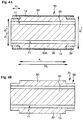
- Fig. 4A is a cross sectional view schematically illustrating a shaping roll (first roll) ID for melt extrusion molding according to embodiment 4 when the first roll ID is taken along a virtual plane including the axial line
- Fig. 4B is a cross sectional view schematically illustrating a roll body part 30.
- a conceptual view illustrating the disposition of the die and the shaping roll assembly for melt extrusion molding is the same as that illustrated in Fig. 1B .
- the first roll ID according to embodiment 4 is a shaping roll for melt extrusion molding used for melt extrusion molding of thermoplastic resin and comprises the roll body part 30 having the heat medium passage 11 internally and cutouts 32 on outer surfaces of both end portions 31 and cylindrical members 33 fitted into the cutouts 32 in the both end portions 31 of the roll body part 30.
- the roll body part 30 is made of a first metal material having a thermal conductivity of 40 W/m ⁇ K or more
- the cylindrical members 33 are made of a second metal material having a thermal conductivity of 20 W/m ⁇ K or less
- the cylindrical members 33 are at least partially joined to the cutouts 32 of the roll body part 30.
- the first metal material of the roll body part 30 and the second metal material of the cylindrical members 33 are specifically indicated in Table 7 below.
- the cylindrical members 33 are shrink-fitted to the roll body part 30.
- the value of the inner diameter D 2-i of the cylindrical members 33 at normal temperatures, the outer diameter D 1-o in the cutouts 32 of the roll body part 30 at normal temperatures, and an outer diameter D' 1-o in a portion 30A of the roll body part 30 between the cutout 32 and the cutout 32 at normal temperatures are indicated in Table 7 below. That is, the shrink-fitting margin is assumed to be 0.15 mm. In addition, the wall thickness of the cylindrical members 33 is assumed to be 8 mm. Also in embodiment 4, the roll body part 30 is assumed to be a so-called drilled roll having the heat medium passage 11 formed into a circular pipe by a cutting drill so as to extend from the side of the roll body part 30 in parallel with the axial direction.
- the number of heat medium passages 11 is essentially arbitrary.
- Thermal oil is used as the heat medium of the roll body part 30.
- the linear expansion coefficient of the second metal material of the cylindrical members 33 is slightly larger than the linear expansion coefficient of the first metal material of the roll body part 30, it is possible to prevent the cylindrical members 33 from being loosened by making the shrink-fitting margin slightly larger.
- the end parts of the cylindrical members 33 may be spot-welded to the roll body part 30 to prevent them from rotating idle or being removed.
- the same plating layer 14 as in embodiment 1 was formed on the surfaces of the roll body part 30 and the cylindrical members 33.
- the same rubber roll made of fluororesin similar as the second roll 2 in embodiment 1 was used as the second roll 2.
- First metal material S45C Thermal conductivity : 45 W/m ⁇ K Linear expansion coefficient 12 ⁇ 10 -6 mm/mm ⁇ K
- Second metal material SUS309 Thermal conductivity : 14 W/m ⁇ K Linear expansion coefficient 15 ⁇ 10 -6 mm/mm ⁇ K D 1-o : 384.0mm D' 1-o : 400.0mm D 2-I :383.7mm D 2-o : 400.0mm X 1 :300 mm X 2 :195mm W 0 :450 mm
- polycarbonate resin polycarbonate resin "lupilon E2000” manufactured by Mitsubishi Engineering-Plastics Corporation
- the nominal thickness of a sheet molded article (film molded article) obtained by a melt extrusion molding method according to embodiment 4 is 130 ⁇ m and the width W 0 is indicated in Table 7.
- the obtained sheet molded article (film molded article) is a light diffusion sheet (light diffusion film) as in embodiment 1 and a mat pattern is formed thereon.
- a well-known melt extrusion molding apparatus is used to pass molten thermoplastic resin pushed out of the die through the gap between the first roll ID and the second roll 2 and apply a pressure to the sheet type molten thermoplastic resin to obtain the sheet molded article (film molded article).
- the molding conditions are indicated in Table 8 below. The appearance of the obtained light diffusion sheet (light diffusion film) was good and the difference in the haze value was hardly observed between the middle part and the end part.
- Die temperature 280°C Line speed : 7 m/min
- First roll temperature 135°C Second roll temperature : 70°C Line pressure level : 6 kg/cm
- the invention has been described above based on preferable embodiments, the invention is not limited to these embodiments.
- the structures, composition, and materials used, melt extrusion molding conditions, and the like of the shaping roll for melt extrusion molding, the shaping roll assembly for melt extrusion molding, and the melt extrusion molding apparatus described in the embodiments are only examples and may be changed as appropriate.
- the plating layer described in embodiment 2 may be applied to embodiment 1 and embodiment 4 and the plating layer described in embodiment 1 may be applied to embodiment 2 and embodiment 3.
Landscapes
- Engineering & Computer Science (AREA)
- Mechanical Engineering (AREA)
- Physics & Mathematics (AREA)
- Thermal Sciences (AREA)
- Manufacturing & Machinery (AREA)
- Extrusion Moulding Of Plastics Or The Like (AREA)
Claims (11)
- Rouleau de façonnage (1D) pour un moulage par extrusion à l'état fondu utilisé pour le moulage par extrusion à l'état fondu d'une résine thermoplastique, le rouleau de façonnage pour un moulage par extrusion à l'état fondu comprenant :une partie de corps de rouleau (30) présentant un passage de milieu thermique (11) intérieurement et des encoches (32) sur des surfaces extérieures des deux portions d'extrémité (31) ; etun élément cylindrique (33) ajusté dans les encoches dans les deux portions d'extrémité (31) de la partie de corps de rouleau ;la partie de corps de rouleau comprenant un premier matériau métallique présentant une conductivité thermique de 40 W/m·K ou plus ;l'élément cylindrique comprenant un second matériau métallique présentant une conductivité thermique de 20 W/m·K ou moins ; etl'élément cylindrique (33) étant attaché de manière non rotative aux encoches (32) de la partie de corps de rouleau (30) ; etdans lequel un diamètre extérieur (D2-O) de l'élément cylindrique (33) à des températures normales est identique à un diamètre extérieur (D'1-O) de la partie de corps de rouleau (30) dans une portion (30A) de la partie de corps de rouleau entre l'encoche (32) et l'encoche (32) à des températures normales.
- Rouleau de façonnage pour un moulage par extrusion à l'état fondu selon la revendication 1, dans lequel une couche de placage est formée sur des surfaces de la partie de corps de rouleau et des éléments cylindriques.
- Rouleau de façonnage pour un moulage par extrusion à l'état fondu selon la revendication 2, dans lequel la couche de placage est sélectionnée à partir d'un groupe incluant une couche de placage de cuivre, une couche de placage de nickel, une couche de placage de nickel chimique-phosphore, une couche de placage de nickel électrolytique-phosphore, et une couche de placage de chrome.
- Rouleau de façonnage pour un moulage par extrusion à l'état fondu selon la revendication 2 ou 3, dans lequel une surface de la couche de placage comprend un motif mat, un motif en prisme, ou un motif de réseau de microlentilles.
- Rouleau de façonnage pour un moulage par extrusion à l'état fondu selon l'une quelconque des revendications 1 à 4, dans lequel le premier matériau métallique comprend de l'acier au carbone, de l'acier chromé, ou de l'acier au molybdène/chrome.
- Rouleau de façonnage pour un moulage par extrusion à l'état fondu selon l'une quelconque des revendications 1 à 5, dans lequel le second matériau métallique comprend de l'acier nickelé ou de l'acide inoxydable.
- Ensemble rouleau de façonnage pour un moulage par extrusion à l'état fondu comprenant :un rouleau de façonnage pour un moulage par extrusion à l'état fondu selon la revendication 1 ; etun rouleau de pression disposé en faisant face au rouleau de façonnage pour un moulage par extrusion à l'état fondu.
- Procédé de moulage par extrusion à l'état fondu en utilisant l'ensemble rouleau de façonnage pour un moulage par extrusion à l'état fondu selon la revendication 7.
- Procédé de moulage par extrusion à l'état fondu selon la revendication 8, dans lequel l'article moulé en feuille obtenu présente une épaisseur de 0,05 mm à 0,5 mm.
- Procédé de moulage par extrusion à l'état fondu selon la revendication 8 ou 9, dans lequel la résine thermoplastique est sélectionnée à partir d'un groupe incluant la résine de polycarbonate, la résine acrylique, la résine de polystyrène, la résine de polyester thermoplastique, la résine de polyoléfine annulaire, et la résine de polyméthyle-1-pentène.
- Procédé de moulage par extrusion à l'état fondu selon l'une quelconque des revendications 8 à 10, dans lequel l'article moulé en feuille obtenu comprend un film de diffusion de lumière ou une feuille d'amélioration de luminosité.
Applications Claiming Priority (1)
| Application Number | Priority Date | Filing Date | Title |
|---|---|---|---|
| PCT/JP2014/060422 WO2015155873A1 (fr) | 2014-04-10 | 2014-04-10 | Rouleau de façonnage pour moulage par extrusion à l'état fondu, ensemble rouleau de façonnage pour moulage par extrusion à l'état fondu, et procédé de moulage par extrusion à l'état fondu |
Publications (3)
| Publication Number | Publication Date |
|---|---|
| EP3130445A1 EP3130445A1 (fr) | 2017-02-15 |
| EP3130445A4 EP3130445A4 (fr) | 2017-12-13 |
| EP3130445B1 true EP3130445B1 (fr) | 2021-06-30 |
Family
ID=54287474
Family Applications (1)
| Application Number | Title | Priority Date | Filing Date |
|---|---|---|---|
| EP14888676.5A Active EP3130445B1 (fr) | 2014-04-10 | 2014-04-10 | Rouleau de façonnage pour moulage par extrusion à l'état fondu, ensemble rouleau de façonnage pour moulage par extrusion à l'état fondu, et procédé de moulage par extrusion à l'état fondu |
Country Status (4)
| Country | Link |
|---|---|
| US (1) | US10213951B2 (fr) |
| EP (1) | EP3130445B1 (fr) |
| KR (1) | KR20160143709A (fr) |
| WO (1) | WO2015155873A1 (fr) |
Families Citing this family (1)
| Publication number | Priority date | Publication date | Assignee | Title |
|---|---|---|---|---|
| JP6776860B2 (ja) * | 2016-12-09 | 2020-10-28 | コニカミノルタ株式会社 | サイジングダイと押出成形装置、およびそれらを用いた管状部材の製造方法 |
Citations (1)
| Publication number | Priority date | Publication date | Assignee | Title |
|---|---|---|---|---|
| EP1666232A2 (fr) * | 2004-11-03 | 2006-06-07 | Sealed Air Corporation (US) | Procédé et dispositif pour fabriquer des articles thermoscellés |
Family Cites Families (19)
| Publication number | Priority date | Publication date | Assignee | Title |
|---|---|---|---|---|
| DE69002372T2 (de) * | 1989-04-26 | 1993-12-09 | Canon Kk | Stanzwalze zum Giessen von Lagen für optische Datenträger, Verfahren zu deren Herstellung und Verfahren zur Herstellung des damit herzustellenden Trägers. |
| JP3162482B2 (ja) | 1992-06-18 | 2001-04-25 | 帝人株式会社 | 芳香族ポリエステルの製造方法 |
| JP2561143Y2 (ja) * | 1992-06-19 | 1998-01-28 | 住友金属工業株式会社 | 多孔ロール |
| JP2911768B2 (ja) | 1994-11-17 | 1999-06-23 | 株式会社淀川製鋼所 | 熱間圧延用ワークロール |
| JP4743373B2 (ja) | 2001-08-21 | 2011-08-10 | 株式会社クラレ | 樹脂シートの製造方法 |
| US6984352B1 (en) * | 2002-05-29 | 2006-01-10 | Akopyan Razmik L | Dielectric mold for uniform heating and molding of polymers and composites in microwave ovens |
| JP2005321013A (ja) | 2004-05-07 | 2005-11-17 | Mitsubishi Heavy Ind Ltd | フィルム成形機用ロールの製造方法、フィルム成形機用ロール |
| US20070001333A1 (en) | 2005-06-30 | 2007-01-04 | Ashwit Dias | System and method for forming textured polymeric films |
| JPWO2007043358A1 (ja) * | 2005-10-07 | 2009-04-16 | コニカミノルタオプト株式会社 | セルロースエステルフィルムの製造方法、セルロースエステルフィルム、偏光板及び液晶表示装置 |
| JP5206407B2 (ja) * | 2006-06-21 | 2013-06-12 | コニカミノルタアドバンストレイヤー株式会社 | 偏光板保護フィルムの製造方法 |
| JP5396074B2 (ja) | 2007-12-20 | 2014-01-22 | 株式会社クラレ | 樹脂シートの製造方法、光学フィルム、及び、樹脂シートの製造装置 |
| JP2009248421A (ja) | 2008-04-04 | 2009-10-29 | Toshiba Mach Co Ltd | シート・フィルム成形ロール及びシート・フィルム成形装置 |
| JP2009248565A (ja) * | 2008-04-07 | 2009-10-29 | Akira Shimizu | 薄膜シート成形用ロール |
| JP5156534B2 (ja) | 2008-08-08 | 2013-03-06 | 住友重機械工業株式会社 | シート成形装置 |
| JP5924337B2 (ja) | 2011-03-31 | 2016-05-25 | 東レ株式会社 | 微細構造転写フィルムの製造方法および製造装置 |
| EP2520409B1 (fr) | 2011-05-03 | 2014-07-16 | Reifenhäuser GmbH & Co. KG Maschinenfabrik | Procédé et dispositif de fabrication d'une feuille pourvue d'un marquage |
| JP5755953B2 (ja) * | 2011-06-29 | 2015-07-29 | 三菱瓦斯化学株式会社 | 溶融押出成形賦形用のロール、溶融押出成形賦形用のロール組立体、及び、溶融押出成形方法 |
| JP6131436B2 (ja) * | 2011-07-27 | 2017-05-24 | 三菱瓦斯化学株式会社 | 溶融押出成形賦形用のロール、及び、溶融押出成形方法 |
| PL2845706T3 (pl) * | 2013-09-10 | 2016-11-30 | Walec do przetwarzania tworzyw sztucznych, urządzenie i sposób wykorzystujący taki walec |
-
2014
- 2014-04-10 KR KR1020167030219A patent/KR20160143709A/ko not_active Withdrawn
- 2014-04-10 EP EP14888676.5A patent/EP3130445B1/fr active Active
- 2014-04-10 WO PCT/JP2014/060422 patent/WO2015155873A1/fr not_active Ceased
- 2014-04-10 US US15/301,817 patent/US10213951B2/en active Active
Patent Citations (1)
| Publication number | Priority date | Publication date | Assignee | Title |
|---|---|---|---|---|
| EP1666232A2 (fr) * | 2004-11-03 | 2006-06-07 | Sealed Air Corporation (US) | Procédé et dispositif pour fabriquer des articles thermoscellés |
Also Published As
| Publication number | Publication date |
|---|---|
| EP3130445A1 (fr) | 2017-02-15 |
| EP3130445A4 (fr) | 2017-12-13 |
| WO2015155873A1 (fr) | 2015-10-15 |
| US20170113395A1 (en) | 2017-04-27 |
| CN106163762A (zh) | 2016-11-23 |
| US10213951B2 (en) | 2019-02-26 |
| KR20160143709A (ko) | 2016-12-14 |
Similar Documents
| Publication | Publication Date | Title |
|---|---|---|
| KR101833110B1 (ko) | T다이 제조 방법 | |
| US20070119212A1 (en) | Axial symmetric molding glass lens, mold assembly for an axial symmetric molding glass lens, method for manufacturing a mold assembly for an axial symmetric molding glass lens and method for manufacturing an axial symmetric molding glass lens | |
| JP5256743B2 (ja) | 光学フィルム製造用のロール金型 | |
| US10213951B2 (en) | Shaping roll for melt extrusion molding, shaping roll assembly for melt extrusion molding, and melt extrusion molding method | |
| JP5755953B2 (ja) | 溶融押出成形賦形用のロール、溶融押出成形賦形用のロール組立体、及び、溶融押出成形方法 | |
| JP2010188626A (ja) | スクリュー及びその製造方法 | |
| CN106163762B (zh) | 熔融挤出成型赋形用的辊、熔融挤出成型赋形用的辊组装体以及熔融挤出成型方法 | |
| JP6131436B2 (ja) | 溶融押出成形賦形用のロール、及び、溶融押出成形方法 | |
| JP6082612B2 (ja) | シート成形品の溶融押出成形装置、及び、溶融押出成形方法 | |
| JPH1110222A (ja) | 熱間押出用ガラスパッド | |
| CN114908346A (zh) | 一种冲压拉伸模具激光熔覆硬质合金强化方法 | |
| JP6078706B2 (ja) | 溶融押出成形賦形用のロール、溶融押出成形賦形用のロール組立体、及び、溶融押出成形方法 | |
| JP6082600B2 (ja) | シート成形品の溶融押出成形装置、及び、溶融押出成形方法 | |
| JP2006224462A (ja) | Tダイ及びそれを用いた熱可塑性樹脂フィルムの製造方法 | |
| CN103031469B (zh) | 表面品质优良的感光鼓用铝管及其制造方法 | |
| TWI601622B (zh) | Melt extrusion molding and shaping rollers, melt extrusion molding and shaping roller assembly, and melt extrusion molding method | |
| JPS61209719A (ja) | ポ−トホ−ルダイス雄型 | |
| JP2009132102A (ja) | Tダイおよびその製造方法 | |
| JP6085175B2 (ja) | 溶融押出成形賦形用のロール組立体、及び、溶融押出成形方法 | |
| JP4841924B2 (ja) | 光学フィルム成形用金型及び光学用熱可塑性樹脂フィルムの製造方法 | |
| JPH0661818B2 (ja) | シート成形用ダイの製造方法 | |
| JP2003154529A (ja) | 光学素子成形用金型 | |
| JP2007196630A (ja) | Tダイ | |
| CN109834437B (zh) | 一种出水管成型工艺 | |
| Hendess et al. | Pipe and Tubing Extrusion |
Legal Events
| Date | Code | Title | Description |
|---|---|---|---|
| STAA | Information on the status of an ep patent application or granted ep patent |
Free format text: STATUS: THE INTERNATIONAL PUBLICATION HAS BEEN MADE |
|
| PUAI | Public reference made under article 153(3) epc to a published international application that has entered the european phase |
Free format text: ORIGINAL CODE: 0009012 |
|
| STAA | Information on the status of an ep patent application or granted ep patent |
Free format text: STATUS: REQUEST FOR EXAMINATION WAS MADE |
|
| 17P | Request for examination filed |
Effective date: 20161019 |
|
| AK | Designated contracting states |
Kind code of ref document: A1 Designated state(s): AL AT BE BG CH CY CZ DE DK EE ES FI FR GB GR HR HU IE IS IT LI LT LU LV MC MK MT NL NO PL PT RO RS SE SI SK SM TR |
|
| AX | Request for extension of the european patent |
Extension state: BA ME |
|
| DAX | Request for extension of the european patent (deleted) | ||
| RIC1 | Information provided on ipc code assigned before grant |
Ipc: B29C 47/88 20060101ALI20171031BHEP Ipc: B29C 43/46 20060101AFI20171031BHEP Ipc: B29L 31/32 20060101ALN20171031BHEP Ipc: B29C 33/38 20060101ALI20171031BHEP Ipc: B29C 47/90 20060101ALI20171031BHEP Ipc: B29C 59/04 20060101ALI20171031BHEP |
|
| A4 | Supplementary search report drawn up and despatched |
Effective date: 20171109 |
|
| STAA | Information on the status of an ep patent application or granted ep patent |
Free format text: STATUS: EXAMINATION IS IN PROGRESS |
|
| 17Q | First examination report despatched |
Effective date: 20190328 |
|
| REG | Reference to a national code |
Ref country code: DE Ref legal event code: R079 Ref document number: 602014078520 Country of ref document: DE Free format text: PREVIOUS MAIN CLASS: B29C0047880000 Ipc: B29C0043460000 |
|
| GRAP | Despatch of communication of intention to grant a patent |
Free format text: ORIGINAL CODE: EPIDOSNIGR1 |
|
| STAA | Information on the status of an ep patent application or granted ep patent |
Free format text: STATUS: GRANT OF PATENT IS INTENDED |
|
| RIC1 | Information provided on ipc code assigned before grant |
Ipc: B29C 48/08 20190101ALI20210303BHEP Ipc: B29L 31/32 20060101ALN20210303BHEP Ipc: B29C 59/04 20060101ALI20210303BHEP Ipc: B29C 48/88 20190101ALI20210303BHEP Ipc: B29C 48/90 20190101ALN20210303BHEP Ipc: B29C 33/38 20060101ALI20210303BHEP Ipc: B29C 43/46 20060101AFI20210303BHEP |
|
| INTG | Intention to grant announced |
Effective date: 20210323 |
|
| GRAS | Grant fee paid |
Free format text: ORIGINAL CODE: EPIDOSNIGR3 |
|
| GRAA | (expected) grant |
Free format text: ORIGINAL CODE: 0009210 |
|
| STAA | Information on the status of an ep patent application or granted ep patent |
Free format text: STATUS: THE PATENT HAS BEEN GRANTED |
|
| AK | Designated contracting states |
Kind code of ref document: B1 Designated state(s): AL AT BE BG CH CY CZ DE DK EE ES FI FR GB GR HR HU IE IS IT LI LT LU LV MC MK MT NL NO PL PT RO RS SE SI SK SM TR |
|
| REG | Reference to a national code |
Ref country code: CH Ref legal event code: EP |
|
| REG | Reference to a national code |
Ref country code: DE Ref legal event code: R096 Ref document number: 602014078520 Country of ref document: DE Ref country code: AT Ref legal event code: REF Ref document number: 1405942 Country of ref document: AT Kind code of ref document: T Effective date: 20210715 |
|
| REG | Reference to a national code |
Ref country code: IE Ref legal event code: FG4D |
|
| REG | Reference to a national code |
Ref country code: LT Ref legal event code: MG9D |
|
| PG25 | Lapsed in a contracting state [announced via postgrant information from national office to epo] |
Ref country code: FI Free format text: LAPSE BECAUSE OF FAILURE TO SUBMIT A TRANSLATION OF THE DESCRIPTION OR TO PAY THE FEE WITHIN THE PRESCRIBED TIME-LIMIT Effective date: 20210630 Ref country code: BG Free format text: LAPSE BECAUSE OF FAILURE TO SUBMIT A TRANSLATION OF THE DESCRIPTION OR TO PAY THE FEE WITHIN THE PRESCRIBED TIME-LIMIT Effective date: 20210930 Ref country code: HR Free format text: LAPSE BECAUSE OF FAILURE TO SUBMIT A TRANSLATION OF THE DESCRIPTION OR TO PAY THE FEE WITHIN THE PRESCRIBED TIME-LIMIT Effective date: 20210630 |
|
| REG | Reference to a national code |
Ref country code: NL Ref legal event code: MP Effective date: 20210630 |
|
| REG | Reference to a national code |
Ref country code: AT Ref legal event code: MK05 Ref document number: 1405942 Country of ref document: AT Kind code of ref document: T Effective date: 20210630 |
|
| PG25 | Lapsed in a contracting state [announced via postgrant information from national office to epo] |
Ref country code: GR Free format text: LAPSE BECAUSE OF FAILURE TO SUBMIT A TRANSLATION OF THE DESCRIPTION OR TO PAY THE FEE WITHIN THE PRESCRIBED TIME-LIMIT Effective date: 20211001 Ref country code: LV Free format text: LAPSE BECAUSE OF FAILURE TO SUBMIT A TRANSLATION OF THE DESCRIPTION OR TO PAY THE FEE WITHIN THE PRESCRIBED TIME-LIMIT Effective date: 20210630 Ref country code: SE Free format text: LAPSE BECAUSE OF FAILURE TO SUBMIT A TRANSLATION OF THE DESCRIPTION OR TO PAY THE FEE WITHIN THE PRESCRIBED TIME-LIMIT Effective date: 20210630 Ref country code: RS Free format text: LAPSE BECAUSE OF FAILURE TO SUBMIT A TRANSLATION OF THE DESCRIPTION OR TO PAY THE FEE WITHIN THE PRESCRIBED TIME-LIMIT Effective date: 20210630 Ref country code: NO Free format text: LAPSE BECAUSE OF FAILURE TO SUBMIT A TRANSLATION OF THE DESCRIPTION OR TO PAY THE FEE WITHIN THE PRESCRIBED TIME-LIMIT Effective date: 20210930 |
|
| PG25 | Lapsed in a contracting state [announced via postgrant information from national office to epo] |
Ref country code: ES Free format text: LAPSE BECAUSE OF FAILURE TO SUBMIT A TRANSLATION OF THE DESCRIPTION OR TO PAY THE FEE WITHIN THE PRESCRIBED TIME-LIMIT Effective date: 20210630 Ref country code: PT Free format text: LAPSE BECAUSE OF FAILURE TO SUBMIT A TRANSLATION OF THE DESCRIPTION OR TO PAY THE FEE WITHIN THE PRESCRIBED TIME-LIMIT Effective date: 20211102 Ref country code: NL Free format text: LAPSE BECAUSE OF FAILURE TO SUBMIT A TRANSLATION OF THE DESCRIPTION OR TO PAY THE FEE WITHIN THE PRESCRIBED TIME-LIMIT Effective date: 20210630 Ref country code: RO Free format text: LAPSE BECAUSE OF FAILURE TO SUBMIT A TRANSLATION OF THE DESCRIPTION OR TO PAY THE FEE WITHIN THE PRESCRIBED TIME-LIMIT Effective date: 20210630 Ref country code: AT Free format text: LAPSE BECAUSE OF FAILURE TO SUBMIT A TRANSLATION OF THE DESCRIPTION OR TO PAY THE FEE WITHIN THE PRESCRIBED TIME-LIMIT Effective date: 20210630 Ref country code: EE Free format text: LAPSE BECAUSE OF FAILURE TO SUBMIT A TRANSLATION OF THE DESCRIPTION OR TO PAY THE FEE WITHIN THE PRESCRIBED TIME-LIMIT Effective date: 20210630 Ref country code: CZ Free format text: LAPSE BECAUSE OF FAILURE TO SUBMIT A TRANSLATION OF THE DESCRIPTION OR TO PAY THE FEE WITHIN THE PRESCRIBED TIME-LIMIT Effective date: 20210630 Ref country code: SK Free format text: LAPSE BECAUSE OF FAILURE TO SUBMIT A TRANSLATION OF THE DESCRIPTION OR TO PAY THE FEE WITHIN THE PRESCRIBED TIME-LIMIT Effective date: 20210630 Ref country code: SM Free format text: LAPSE BECAUSE OF FAILURE TO SUBMIT A TRANSLATION OF THE DESCRIPTION OR TO PAY THE FEE WITHIN THE PRESCRIBED TIME-LIMIT Effective date: 20210630 |
|
| PG25 | Lapsed in a contracting state [announced via postgrant information from national office to epo] |
Ref country code: PL Free format text: LAPSE BECAUSE OF FAILURE TO SUBMIT A TRANSLATION OF THE DESCRIPTION OR TO PAY THE FEE WITHIN THE PRESCRIBED TIME-LIMIT Effective date: 20210630 |
|
| REG | Reference to a national code |
Ref country code: DE Ref legal event code: R097 Ref document number: 602014078520 Country of ref document: DE |
|
| PG25 | Lapsed in a contracting state [announced via postgrant information from national office to epo] |
Ref country code: DK Free format text: LAPSE BECAUSE OF FAILURE TO SUBMIT A TRANSLATION OF THE DESCRIPTION OR TO PAY THE FEE WITHIN THE PRESCRIBED TIME-LIMIT Effective date: 20210630 |
|
| PLBE | No opposition filed within time limit |
Free format text: ORIGINAL CODE: 0009261 |
|
| STAA | Information on the status of an ep patent application or granted ep patent |
Free format text: STATUS: NO OPPOSITION FILED WITHIN TIME LIMIT |
|
| PG25 | Lapsed in a contracting state [announced via postgrant information from national office to epo] |
Ref country code: AL Free format text: LAPSE BECAUSE OF FAILURE TO SUBMIT A TRANSLATION OF THE DESCRIPTION OR TO PAY THE FEE WITHIN THE PRESCRIBED TIME-LIMIT Effective date: 20210630 |
|
| 26N | No opposition filed |
Effective date: 20220331 |
|
| PG25 | Lapsed in a contracting state [announced via postgrant information from national office to epo] |
Ref country code: IT Free format text: LAPSE BECAUSE OF FAILURE TO SUBMIT A TRANSLATION OF THE DESCRIPTION OR TO PAY THE FEE WITHIN THE PRESCRIBED TIME-LIMIT Effective date: 20210630 |
|
| REG | Reference to a national code |
Ref country code: CH Ref legal event code: PL |
|
| GBPC | Gb: european patent ceased through non-payment of renewal fee |
Effective date: 20220410 |
|
| REG | Reference to a national code |
Ref country code: BE Ref legal event code: MM Effective date: 20220430 |
|
| PG25 | Lapsed in a contracting state [announced via postgrant information from national office to epo] |
Ref country code: MC Free format text: LAPSE BECAUSE OF FAILURE TO SUBMIT A TRANSLATION OF THE DESCRIPTION OR TO PAY THE FEE WITHIN THE PRESCRIBED TIME-LIMIT Effective date: 20210630 Ref country code: LU Free format text: LAPSE BECAUSE OF NON-PAYMENT OF DUE FEES Effective date: 20220410 Ref country code: LI Free format text: LAPSE BECAUSE OF NON-PAYMENT OF DUE FEES Effective date: 20220430 Ref country code: GB Free format text: LAPSE BECAUSE OF NON-PAYMENT OF DUE FEES Effective date: 20220410 Ref country code: FR Free format text: LAPSE BECAUSE OF NON-PAYMENT OF DUE FEES Effective date: 20220430 Ref country code: CH Free format text: LAPSE BECAUSE OF NON-PAYMENT OF DUE FEES Effective date: 20220430 |
|
| PG25 | Lapsed in a contracting state [announced via postgrant information from national office to epo] |
Ref country code: BE Free format text: LAPSE BECAUSE OF NON-PAYMENT OF DUE FEES Effective date: 20220430 |
|
| PG25 | Lapsed in a contracting state [announced via postgrant information from national office to epo] |
Ref country code: LT Free format text: LAPSE BECAUSE OF FAILURE TO SUBMIT A TRANSLATION OF THE DESCRIPTION OR TO PAY THE FEE WITHIN THE PRESCRIBED TIME-LIMIT Effective date: 20210630 Ref country code: IE Free format text: LAPSE BECAUSE OF NON-PAYMENT OF DUE FEES Effective date: 20220410 |
|
| PG25 | Lapsed in a contracting state [announced via postgrant information from national office to epo] |
Ref country code: HU Free format text: LAPSE BECAUSE OF FAILURE TO SUBMIT A TRANSLATION OF THE DESCRIPTION OR TO PAY THE FEE WITHIN THE PRESCRIBED TIME-LIMIT; INVALID AB INITIO Effective date: 20140410 |
|
| PG25 | Lapsed in a contracting state [announced via postgrant information from national office to epo] |
Ref country code: MK Free format text: LAPSE BECAUSE OF FAILURE TO SUBMIT A TRANSLATION OF THE DESCRIPTION OR TO PAY THE FEE WITHIN THE PRESCRIBED TIME-LIMIT Effective date: 20210630 Ref country code: CY Free format text: LAPSE BECAUSE OF FAILURE TO SUBMIT A TRANSLATION OF THE DESCRIPTION OR TO PAY THE FEE WITHIN THE PRESCRIBED TIME-LIMIT Effective date: 20210630 |
|
| PG25 | Lapsed in a contracting state [announced via postgrant information from national office to epo] |
Ref country code: TR Free format text: LAPSE BECAUSE OF FAILURE TO SUBMIT A TRANSLATION OF THE DESCRIPTION OR TO PAY THE FEE WITHIN THE PRESCRIBED TIME-LIMIT Effective date: 20210630 |
|
| PGFP | Annual fee paid to national office [announced via postgrant information from national office to epo] |
Ref country code: DE Payment date: 20240227 Year of fee payment: 11 |
|
| PG25 | Lapsed in a contracting state [announced via postgrant information from national office to epo] |
Ref country code: MT Free format text: LAPSE BECAUSE OF FAILURE TO SUBMIT A TRANSLATION OF THE DESCRIPTION OR TO PAY THE FEE WITHIN THE PRESCRIBED TIME-LIMIT Effective date: 20210630 |
|
| REG | Reference to a national code |
Ref country code: DE Ref legal event code: R119 Ref document number: 602014078520 Country of ref document: DE |
|
| PG25 | Lapsed in a contracting state [announced via postgrant information from national office to epo] |
Ref country code: DE Free format text: LAPSE BECAUSE OF NON-PAYMENT OF DUE FEES Effective date: 20251104 |