EP3130708A1 - Hybride arbeitsmaschine - Google Patents
Hybride arbeitsmaschine Download PDFInfo
- Publication number
- EP3130708A1 EP3130708A1 EP15776987.8A EP15776987A EP3130708A1 EP 3130708 A1 EP3130708 A1 EP 3130708A1 EP 15776987 A EP15776987 A EP 15776987A EP 3130708 A1 EP3130708 A1 EP 3130708A1
- Authority
- EP
- European Patent Office
- Prior art keywords
- buses
- electric motor
- torque
- voltage
- work machine
- Prior art date
- Legal status (The legal status is an assumption and is not a legal conclusion. Google has not performed a legal analysis and makes no representation as to the accuracy of the status listed.)
- Granted
Links
Images





Classifications
-
- B—PERFORMING OPERATIONS; TRANSPORTING
- B60—VEHICLES IN GENERAL
- B60W—CONJOINT CONTROL OF VEHICLE SUB-UNITS OF DIFFERENT TYPE OR DIFFERENT FUNCTION; CONTROL SYSTEMS SPECIALLY ADAPTED FOR HYBRID VEHICLES; ROAD VEHICLE DRIVE CONTROL SYSTEMS FOR PURPOSES NOT RELATED TO THE CONTROL OF A PARTICULAR SUB-UNIT
- B60W20/00—Control systems specially adapted for hybrid vehicles
- B60W20/10—Controlling the power contribution of each of the prime movers to meet required power demand
-
- B—PERFORMING OPERATIONS; TRANSPORTING
- B60—VEHICLES IN GENERAL
- B60K—ARRANGEMENT OR MOUNTING OF PROPULSION UNITS OR OF TRANSMISSIONS IN VEHICLES; ARRANGEMENT OR MOUNTING OF PLURAL DIVERSE PRIME-MOVERS IN VEHICLES; AUXILIARY DRIVES FOR VEHICLES; INSTRUMENTATION OR DASHBOARDS FOR VEHICLES; ARRANGEMENTS IN CONNECTION WITH COOLING, AIR INTAKE, GAS EXHAUST OR FUEL SUPPLY OF PROPULSION UNITS IN VEHICLES
- B60K25/00—Auxiliary drives
- B60K25/02—Auxiliary drives directly from an engine shaft
-
- B—PERFORMING OPERATIONS; TRANSPORTING
- B60—VEHICLES IN GENERAL
- B60K—ARRANGEMENT OR MOUNTING OF PROPULSION UNITS OR OF TRANSMISSIONS IN VEHICLES; ARRANGEMENT OR MOUNTING OF PLURAL DIVERSE PRIME-MOVERS IN VEHICLES; AUXILIARY DRIVES FOR VEHICLES; INSTRUMENTATION OR DASHBOARDS FOR VEHICLES; ARRANGEMENTS IN CONNECTION WITH COOLING, AIR INTAKE, GAS EXHAUST OR FUEL SUPPLY OF PROPULSION UNITS IN VEHICLES
- B60K6/00—Arrangement or mounting of plural diverse prime-movers for mutual or common propulsion, e.g. hybrid propulsion systems comprising electric motors and internal combustion engines
- B60K6/20—Arrangement or mounting of plural diverse prime-movers for mutual or common propulsion, e.g. hybrid propulsion systems comprising electric motors and internal combustion engines the prime-movers consisting of electric motors and internal combustion engines, e.g. HEVs
- B60K6/42—Arrangement or mounting of plural diverse prime-movers for mutual or common propulsion, e.g. hybrid propulsion systems comprising electric motors and internal combustion engines the prime-movers consisting of electric motors and internal combustion engines, e.g. HEVs characterised by the architecture of the hybrid electric vehicle
- B60K6/46—Series type
-
- B—PERFORMING OPERATIONS; TRANSPORTING
- B60—VEHICLES IN GENERAL
- B60K—ARRANGEMENT OR MOUNTING OF PROPULSION UNITS OR OF TRANSMISSIONS IN VEHICLES; ARRANGEMENT OR MOUNTING OF PLURAL DIVERSE PRIME-MOVERS IN VEHICLES; AUXILIARY DRIVES FOR VEHICLES; INSTRUMENTATION OR DASHBOARDS FOR VEHICLES; ARRANGEMENTS IN CONNECTION WITH COOLING, AIR INTAKE, GAS EXHAUST OR FUEL SUPPLY OF PROPULSION UNITS IN VEHICLES
- B60K6/00—Arrangement or mounting of plural diverse prime-movers for mutual or common propulsion, e.g. hybrid propulsion systems comprising electric motors and internal combustion engines
- B60K6/20—Arrangement or mounting of plural diverse prime-movers for mutual or common propulsion, e.g. hybrid propulsion systems comprising electric motors and internal combustion engines the prime-movers consisting of electric motors and internal combustion engines, e.g. HEVs
- B60K6/50—Architecture of the driveline characterised by arrangement or kind of transmission units
-
- E—FIXED CONSTRUCTIONS
- E02—HYDRAULIC ENGINEERING; FOUNDATIONS; SOIL SHIFTING
- E02F—DREDGING; SOIL-SHIFTING
- E02F3/00—Dredgers; Soil-shifting machines
- E02F3/04—Dredgers; Soil-shifting machines mechanically-driven
- E02F3/28—Dredgers; Soil-shifting machines mechanically-driven with digging tools mounted on a dipper- or bucket-arm, i.e. there is either one arm or a pair of arms, e.g. dippers, buckets
- E02F3/34—Dredgers; Soil-shifting machines mechanically-driven with digging tools mounted on a dipper- or bucket-arm, i.e. there is either one arm or a pair of arms, e.g. dippers, buckets with bucket-arms, i.e. a pair of arms, e.g. manufacturing processes, form, geometry, material of bucket-arms directly pivoted on the frames of tractors or self-propelled machines
-
- E—FIXED CONSTRUCTIONS
- E02—HYDRAULIC ENGINEERING; FOUNDATIONS; SOIL SHIFTING
- E02F—DREDGING; SOIL-SHIFTING
- E02F9/00—Component parts of dredgers or soil-shifting machines, not restricted to one of the kinds covered by groups E02F3/00 - E02F7/00
- E02F9/20—Drives; Control devices
-
- E—FIXED CONSTRUCTIONS
- E02—HYDRAULIC ENGINEERING; FOUNDATIONS; SOIL SHIFTING
- E02F—DREDGING; SOIL-SHIFTING
- E02F9/00—Component parts of dredgers or soil-shifting machines, not restricted to one of the kinds covered by groups E02F3/00 - E02F7/00
- E02F9/20—Drives; Control devices
- E02F9/2058—Electric or electro-mechanical or mechanical control devices of vehicle sub-units
- E02F9/2062—Control of propulsion units
- E02F9/2075—Control of propulsion units of the hybrid type
-
- E—FIXED CONSTRUCTIONS
- E02—HYDRAULIC ENGINEERING; FOUNDATIONS; SOIL SHIFTING
- E02F—DREDGING; SOIL-SHIFTING
- E02F9/00—Component parts of dredgers or soil-shifting machines, not restricted to one of the kinds covered by groups E02F3/00 - E02F7/00
- E02F9/20—Drives; Control devices
- E02F9/2058—Electric or electro-mechanical or mechanical control devices of vehicle sub-units
- E02F9/2091—Control of energy storage means for electrical energy, e.g. battery or capacitors
-
- E—FIXED CONSTRUCTIONS
- E02—HYDRAULIC ENGINEERING; FOUNDATIONS; SOIL SHIFTING
- E02F—DREDGING; SOIL-SHIFTING
- E02F9/00—Component parts of dredgers or soil-shifting machines, not restricted to one of the kinds covered by groups E02F3/00 - E02F7/00
- E02F9/20—Drives; Control devices
- E02F9/2058—Electric or electro-mechanical or mechanical control devices of vehicle sub-units
- E02F9/2095—Control of electric, electro-mechanical or mechanical equipment not otherwise provided for, e.g. ventilators, electro-driven fans
-
- H—ELECTRICITY
- H02—GENERATION; CONVERSION OR DISTRIBUTION OF ELECTRIC POWER
- H02M—APPARATUS FOR CONVERSION BETWEEN AC AND AC, BETWEEN AC AND DC, OR BETWEEN DC AND DC, AND FOR USE WITH MAINS OR SIMILAR POWER SUPPLY SYSTEMS; CONVERSION OF DC OR AC INPUT POWER INTO SURGE OUTPUT POWER; CONTROL OR REGULATION THEREOF
- H02M1/00—Details of apparatus for conversion
- H02M1/0067—Converter structures employing plural converter units, other than for parallel operation of the units on a single load
- H02M1/007—Plural converter units in cascade
-
- H—ELECTRICITY
- H02—GENERATION; CONVERSION OR DISTRIBUTION OF ELECTRIC POWER
- H02M—APPARATUS FOR CONVERSION BETWEEN AC AND AC, BETWEEN AC AND DC, OR BETWEEN DC AND DC, AND FOR USE WITH MAINS OR SIMILAR POWER SUPPLY SYSTEMS; CONVERSION OF DC OR AC INPUT POWER INTO SURGE OUTPUT POWER; CONTROL OR REGULATION THEREOF
- H02M3/00—Conversion of DC power input into DC power output
- H02M3/02—Conversion of DC power input into DC power output without intermediate conversion into AC
- H02M3/04—Conversion of DC power input into DC power output without intermediate conversion into AC by static converters
- H02M3/10—Conversion of DC power input into DC power output without intermediate conversion into AC by static converters using discharge tubes with control electrode or semiconductor devices with control electrode
- H02M3/145—Conversion of DC power input into DC power output without intermediate conversion into AC by static converters using discharge tubes with control electrode or semiconductor devices with control electrode using devices of a triode or transistor type requiring continuous application of a control signal
- H02M3/155—Conversion of DC power input into DC power output without intermediate conversion into AC by static converters using discharge tubes with control electrode or semiconductor devices with control electrode using devices of a triode or transistor type requiring continuous application of a control signal using semiconductor devices only
-
- H—ELECTRICITY
- H02—GENERATION; CONVERSION OR DISTRIBUTION OF ELECTRIC POWER
- H02M—APPARATUS FOR CONVERSION BETWEEN AC AND AC, BETWEEN AC AND DC, OR BETWEEN DC AND DC, AND FOR USE WITH MAINS OR SIMILAR POWER SUPPLY SYSTEMS; CONVERSION OF DC OR AC INPUT POWER INTO SURGE OUTPUT POWER; CONTROL OR REGULATION THEREOF
- H02M7/00—Conversion of AC power input into DC power output; Conversion of DC power input into AC power output
- H02M7/42—Conversion of DC power input into AC power output without possibility of reversal
- H02M7/44—Conversion of DC power input into AC power output without possibility of reversal by static converters
- H02M7/48—Conversion of DC power input into AC power output without possibility of reversal by static converters using discharge tubes with control electrode or semiconductor devices with control electrode
- H02M7/53—Conversion of DC power input into AC power output without possibility of reversal by static converters using discharge tubes with control electrode or semiconductor devices with control electrode using devices of a triode or transistor type requiring continuous application of a control signal
- H02M7/537—Conversion of DC power input into AC power output without possibility of reversal by static converters using discharge tubes with control electrode or semiconductor devices with control electrode using devices of a triode or transistor type requiring continuous application of a control signal using semiconductor devices only, e.g. single switched pulse inverters
- H02M7/5387—Conversion of DC power input into AC power output without possibility of reversal by static converters using discharge tubes with control electrode or semiconductor devices with control electrode using devices of a triode or transistor type requiring continuous application of a control signal using semiconductor devices only, e.g. single switched pulse inverters in a bridge configuration
-
- H—ELECTRICITY
- H02—GENERATION; CONVERSION OR DISTRIBUTION OF ELECTRIC POWER
- H02P—CONTROL OR REGULATION OF ELECTRIC MOTORS, ELECTRIC GENERATORS OR DYNAMO-ELECTRIC CONVERTERS; CONTROLLING TRANSFORMERS, REACTORS OR CHOKE COILS
- H02P7/00—Arrangements for regulating or controlling the speed or torque of electric DC motors
- H02P7/06—Arrangements for regulating or controlling the speed or torque of electric DC motors for regulating or controlling an individual DC dynamo-electric motor by varying field or armature current
- H02P7/18—Arrangements for regulating or controlling the speed or torque of electric DC motors for regulating or controlling an individual DC dynamo-electric motor by varying field or armature current by master control with auxiliary power
-
- B—PERFORMING OPERATIONS; TRANSPORTING
- B60—VEHICLES IN GENERAL
- B60K—ARRANGEMENT OR MOUNTING OF PROPULSION UNITS OR OF TRANSMISSIONS IN VEHICLES; ARRANGEMENT OR MOUNTING OF PLURAL DIVERSE PRIME-MOVERS IN VEHICLES; AUXILIARY DRIVES FOR VEHICLES; INSTRUMENTATION OR DASHBOARDS FOR VEHICLES; ARRANGEMENTS IN CONNECTION WITH COOLING, AIR INTAKE, GAS EXHAUST OR FUEL SUPPLY OF PROPULSION UNITS IN VEHICLES
- B60K25/00—Auxiliary drives
- B60K25/02—Auxiliary drives directly from an engine shaft
- B60K2025/026—Auxiliary drives directly from an engine shaft by a hydraulic transmission
-
- B—PERFORMING OPERATIONS; TRANSPORTING
- B60—VEHICLES IN GENERAL
- B60W—CONJOINT CONTROL OF VEHICLE SUB-UNITS OF DIFFERENT TYPE OR DIFFERENT FUNCTION; CONTROL SYSTEMS SPECIALLY ADAPTED FOR HYBRID VEHICLES; ROAD VEHICLE DRIVE CONTROL SYSTEMS FOR PURPOSES NOT RELATED TO THE CONTROL OF A PARTICULAR SUB-UNIT
- B60W2300/00—Indexing codes relating to the type of vehicle
- B60W2300/17—Construction vehicles, e.g. graders, excavators
-
- B—PERFORMING OPERATIONS; TRANSPORTING
- B60—VEHICLES IN GENERAL
- B60W—CONJOINT CONTROL OF VEHICLE SUB-UNITS OF DIFFERENT TYPE OR DIFFERENT FUNCTION; CONTROL SYSTEMS SPECIALLY ADAPTED FOR HYBRID VEHICLES; ROAD VEHICLE DRIVE CONTROL SYSTEMS FOR PURPOSES NOT RELATED TO THE CONTROL OF A PARTICULAR SUB-UNIT
- B60W2510/00—Input parameters relating to a particular sub-units
- B60W2510/08—Electric propulsion units
- B60W2510/081—Speed
-
- B—PERFORMING OPERATIONS; TRANSPORTING
- B60—VEHICLES IN GENERAL
- B60W—CONJOINT CONTROL OF VEHICLE SUB-UNITS OF DIFFERENT TYPE OR DIFFERENT FUNCTION; CONTROL SYSTEMS SPECIALLY ADAPTED FOR HYBRID VEHICLES; ROAD VEHICLE DRIVE CONTROL SYSTEMS FOR PURPOSES NOT RELATED TO THE CONTROL OF A PARTICULAR SUB-UNIT
- B60W2510/00—Input parameters relating to a particular sub-units
- B60W2510/08—Electric propulsion units
- B60W2510/083—Torque
-
- B—PERFORMING OPERATIONS; TRANSPORTING
- B60—VEHICLES IN GENERAL
- B60W—CONJOINT CONTROL OF VEHICLE SUB-UNITS OF DIFFERENT TYPE OR DIFFERENT FUNCTION; CONTROL SYSTEMS SPECIALLY ADAPTED FOR HYBRID VEHICLES; ROAD VEHICLE DRIVE CONTROL SYSTEMS FOR PURPOSES NOT RELATED TO THE CONTROL OF A PARTICULAR SUB-UNIT
- B60W2710/00—Output or target parameters relating to a particular sub-units
- B60W2710/08—Electric propulsion units
- B60W2710/083—Torque
-
- B—PERFORMING OPERATIONS; TRANSPORTING
- B60—VEHICLES IN GENERAL
- B60W—CONJOINT CONTROL OF VEHICLE SUB-UNITS OF DIFFERENT TYPE OR DIFFERENT FUNCTION; CONTROL SYSTEMS SPECIALLY ADAPTED FOR HYBRID VEHICLES; ROAD VEHICLE DRIVE CONTROL SYSTEMS FOR PURPOSES NOT RELATED TO THE CONTROL OF A PARTICULAR SUB-UNIT
- B60W2710/00—Output or target parameters relating to a particular sub-units
- B60W2710/08—Electric propulsion units
- B60W2710/086—Power
-
- B—PERFORMING OPERATIONS; TRANSPORTING
- B60—VEHICLES IN GENERAL
- B60Y—INDEXING SCHEME RELATING TO ASPECTS CROSS-CUTTING VEHICLE TECHNOLOGY
- B60Y2200/00—Type of vehicle
- B60Y2200/90—Vehicles comprising electric prime movers
- B60Y2200/92—Hybrid vehicles
-
- B—PERFORMING OPERATIONS; TRANSPORTING
- B60—VEHICLES IN GENERAL
- B60Y—INDEXING SCHEME RELATING TO ASPECTS CROSS-CUTTING VEHICLE TECHNOLOGY
- B60Y2300/00—Purposes or special features of road vehicle drive control systems
- B60Y2300/18—Propelling the vehicle
-
- B—PERFORMING OPERATIONS; TRANSPORTING
- B60—VEHICLES IN GENERAL
- B60Y—INDEXING SCHEME RELATING TO ASPECTS CROSS-CUTTING VEHICLE TECHNOLOGY
- B60Y2300/00—Purposes or special features of road vehicle drive control systems
- B60Y2300/60—Control of electric machines, e.g. problems related to electric motors or generators
-
- B—PERFORMING OPERATIONS; TRANSPORTING
- B60—VEHICLES IN GENERAL
- B60Y—INDEXING SCHEME RELATING TO ASPECTS CROSS-CUTTING VEHICLE TECHNOLOGY
- B60Y2400/00—Special features of vehicle units
- B60Y2400/87—Auxiliary drives
-
- E—FIXED CONSTRUCTIONS
- E02—HYDRAULIC ENGINEERING; FOUNDATIONS; SOIL SHIFTING
- E02F—DREDGING; SOIL-SHIFTING
- E02F3/00—Dredgers; Soil-shifting machines
- E02F3/04—Dredgers; Soil-shifting machines mechanically-driven
- E02F3/28—Dredgers; Soil-shifting machines mechanically-driven with digging tools mounted on a dipper- or bucket-arm, i.e. there is either one arm or a pair of arms, e.g. dippers, buckets
- E02F3/34—Dredgers; Soil-shifting machines mechanically-driven with digging tools mounted on a dipper- or bucket-arm, i.e. there is either one arm or a pair of arms, e.g. dippers, buckets with bucket-arms, i.e. a pair of arms, e.g. manufacturing processes, form, geometry, material of bucket-arms directly pivoted on the frames of tractors or self-propelled machines
- E02F3/3417—Buckets emptying by tilting
-
- E—FIXED CONSTRUCTIONS
- E02—HYDRAULIC ENGINEERING; FOUNDATIONS; SOIL SHIFTING
- E02F—DREDGING; SOIL-SHIFTING
- E02F9/00—Component parts of dredgers or soil-shifting machines, not restricted to one of the kinds covered by groups E02F3/00 - E02F7/00
- E02F9/20—Drives; Control devices
- E02F9/2058—Electric or electro-mechanical or mechanical control devices of vehicle sub-units
- E02F9/2079—Control of mechanical transmission
-
- Y—GENERAL TAGGING OF NEW TECHNOLOGICAL DEVELOPMENTS; GENERAL TAGGING OF CROSS-SECTIONAL TECHNOLOGIES SPANNING OVER SEVERAL SECTIONS OF THE IPC; TECHNICAL SUBJECTS COVERED BY FORMER USPC CROSS-REFERENCE ART COLLECTIONS [XRACs] AND DIGESTS
- Y02—TECHNOLOGIES OR APPLICATIONS FOR MITIGATION OR ADAPTATION AGAINST CLIMATE CHANGE
- Y02T—CLIMATE CHANGE MITIGATION TECHNOLOGIES RELATED TO TRANSPORTATION
- Y02T10/00—Road transport of goods or passengers
- Y02T10/60—Other road transportation technologies with climate change mitigation effect
- Y02T10/62—Hybrid vehicles
-
- Y—GENERAL TAGGING OF NEW TECHNOLOGICAL DEVELOPMENTS; GENERAL TAGGING OF CROSS-SECTIONAL TECHNOLOGIES SPANNING OVER SEVERAL SECTIONS OF THE IPC; TECHNICAL SUBJECTS COVERED BY FORMER USPC CROSS-REFERENCE ART COLLECTIONS [XRACs] AND DIGESTS
- Y10—TECHNICAL SUBJECTS COVERED BY FORMER USPC
- Y10S—TECHNICAL SUBJECTS COVERED BY FORMER USPC CROSS-REFERENCE ART COLLECTIONS [XRACs] AND DIGESTS
- Y10S903/00—Hybrid electric vehicles, HEVS
- Y10S903/902—Prime movers comprising electrical and internal combustion motors
- Y10S903/903—Prime movers comprising electrical and internal combustion motors having energy storing means, e.g. battery, capacitor
- Y10S903/904—Component specially adapted for hev
- Y10S903/915—Specific drive or transmission adapted for hev
Definitions
- the present invention relates to a hybrid work machine, such as a wheel loader, having a driving mechanism, a part of which is motorized.
- Hybrid work machines have conventionally been known in which an engine-assist motor generator is attached to an engine which drives a hydraulic pump, and a partially motorized driving mechanism is employed instead of a hydraulic driving mechanism, such as a hydraulic cylinder and a hydraulic motor.
- This type of hybrid work machine includes an electricity storage device to store generated power from the motor generator and regenerative power of an electric motor, and a power converter to convert these electric powers, a buck-boost converter and the like.
- the motor generator is connected via the power converter to a DC bus, and the DC bus is connected via the buck-boost converter to the electricity storage device.
- the electric motor is connected via another power converter to the DC bus.
- the buck-boost converter boosts a voltage supplied by the electricity storage device to a DC input voltage to the power converter and the power converter converts DC to AC so as to drive the motor generator.
- the electric motor performs regenerative operation, the regenerative power is converted to a DC voltage by the power converter, and is stepped down by the buck-boost converter and then stored in the electricity storage device.
- each of an engine-assist motor generator and an electric motor for turning is provided with a buck-boost converter and a DC bus from a common electricity storage device in order that different voltages are obtainable on these DC buses. That is, in the engine-assist motor generator to be used only at a constant rotation speed, the DC bus (an input DC voltage to a power converter) is set to an approximately constant voltage value. In the electric motor for driving turning whose output frequently changes according to a lever operation amount, a voltage value at the DC bus is allowed to change according to a rotation speed of the electric motor for turning, thereby achieving efficient driving.
- the DC bus voltage needed by the electric motor strongly depends not only on the rotation speed of the electric motor but also on magnitude of load. Therefore, with the method of variably controlling the DC bus voltage according to the rotation speed of the electric motor as described in PTL1, when applied to a system subjected to a large load for a short time irrespective of the rotation speed of the electric motor, such as a travel motor for a wheel loader, the electric motor may fail to develop output necessary for traveling.
- the DC bus voltage has usually been controlled at a fixed value all the time with respect to an electric motor driving system subjected to the large load for the short time.
- the electric motor is capable of developing a maximum torque according to the rotation speed of the electric motor.
- the present invention has been made in view of the above problems, and aims at providing a hybrid work machine that makes it possible to improve a maximum output of an electric motor for a short time while reducing heat generation in a power converter connected to the electric motor, thereby improving working efficiency.
- a hybrid work machine comprises: an engine configured to drive a hydraulic pump as a hydraulic source of a hydraulic actuator; an engine-assist motor generator attached to the engine; an electric motor for use in a part of a driving system of the work machine; an electricity storage device configured to store generated power of the motor generator; a power converter disposed between the electric motor and DC buses; and a buck-boost converter disposed between the DC buses and the electricity storage device, and configured to perform power transfer between the DC buses and the electricity storage device by raising and lowering a voltage of the DC buses, the hybrid work machine, further comprises: a controller configured to temporarily raise the voltage of the DC buses when a torque required for the electric motor exceeds a torque outputtable at the voltage of the DC buses connected to the power converter.
- Fig. 1 is a side view showing a wheel loader, as an example of hybrid work machines to which the present invention is applied, in a situation before inserting a bucket into a mound of earth and sand.
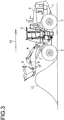
- Figs. 2 and 3 respectively show a situation where the bucket is inserted into the mound of earth and sand, and a situation where the bucket is lifted.
- reference numeral 1 denotes a vehicle body of the wheel loader
- reference numerals 2 and 3 respectively denote a front wheel and a rear wheel of the wheel loader which are respectively attached to a front part and a rear part of the vehicle body 1.
- a power source device 4 and an operator's cab 5, which are described later, are mounted on the vehicle body 1.
- a boom (also called lift arm) 6 is attached to the front part of the vehicle body 1 so as to be vertically movable by a boom cylinder 7 composed of a hydraulic cylinder.
- a bucket 8 is attached to the boom 6 so as to be vertically movable by a bucket cylinder 9 composed of a hydraulic cylinder.
- the wheel loader includes an electric motor (travel motor) 50 (refer to Fig. 4 ) as an electric motor for use in a part of a driving system of the work machine. As shown in Fig. 1 , the wheel loader is moved forth as indicated by an arrow 11 by causing the rear wheels 3 to rotate with driving of the electric motor 50, in a posture in which the bucket 8 is lowered.
- the bucket 8 is rotated upward as indicated by an arrow 13 by extending the bucket cylinder 9 while inserting the bucket 8 into the mound of earth and sand 12 as shown in Fig. 2 , and the boom 6 is lifted by extending the boom cylinder 7. Thereafter, as shown in Fig. 3 , the wheel loader is moved back as indicated by an arrow 14, and subsequently travels to a bed of a truck or a collection place and then deposits soil.
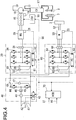
- Fig. 4 is a circuit diagram showing an embodiment of a hydraulic electrical circuit of the hybrid work machine (or hybrid work machine) of the present invention.
- the hybrid work machine according to the present embodiment has a hydraulic driving section and a travel driving section.
- a thick line indicates a hydraulic circuit
- a thin line indicates a power line
- a broken line indicates an electrical signal line.
- Reference numeral 15 denotes an engine.
- Reference numeral 16 denotes a hydraulic pump to be driven by the engine 15.
- Reference numeral 20 denotes an engine-assist motor generator attached to the engine 15.
- Reference numeral 18 denotes an engine control unit (ECU).
- Reference numeral 19 denotes an starter of the engine.
- These elements constitute the power source device 4 shown in Figs. 1 to 3 .
- Reference numeral 17 denotes a control valve to control a direction of hydraulic oil toward the boom cylinder 7 and the bucket cylinder 9, and its flow rate.
- the motor generator 20 drives the engine 15 to assist the engine 15 when functioning as an electric motor, and also operates as a generator for power generation by receiving power from the engine 15 during normal traveling or during deceleration.
- the motor generator 20 is directly coupled to a crankshaft of the engine 15, or is coupled to the crankshaft of the engine 15 with a belt or gear interposed therebetween.
- the motor generator 20 is a permanent magnet synchronous generator.
- Reference numeral 21 denotes a rotation sensor to detect a rotation speed of the motor generator 20.
- Reference numeral 30 denotes a three-phase inverter (first power converter) disposed between both DC buses 80 and 81 and the motor generator 20.
- Reference numeral 42 denotes an electricity storage device.
- Reference numeral 40 denotes a buck-boost converter disposed between both the DC buses 80 and 81 and the electricity storage device 42.
- Reference numeral 50 denotes an electric motor configured to function as a travel motor.
- Reference numeral 60 denotes a three-phase inverter (second power converter) disposed between both the DC buses 80 and 81 and the electric motor 50.
- Reference numeral 70 denotes a hybrid control unit HCU which controls the engine 15, the inverter 30, the buck-boost converter 40, and the inverter 60 via the engine control unit (ECU) 18, power controllers (PCs) 33, 43, and 63, respectively.
- Reference numeral 90 denotes a controller area network (CAN) that establishes a connection between the HCU 70 and the ECU 18, the PCs 33, 43, and 63.
- CAN controller area network
- the inverter 30 converts the generated AC power to DC power and feeds this to the electricity storage device 42 via the DC buses 80 and 81 and the buck-boost converter 40.
- the inverter 30 converts the DC power stored in the electricity storage device 42 to AC power to drive the motor generator 20.
- the inverter 30 includes six semiconductor switches 34. Although IGBTs are used as the semiconductor switches 34 of the inverter 30 in the present embodiment, other power semiconductor elements may be used.
- Reference numeral 31 denotes a motor current sensor to detect a current of the motor generator 20.
- Reference numeral 32 denotes a bus voltage sensor to detect voltage of the DC buses 80 and 81.
- Reference numeral 36 denotes a capacitor to smooth DC voltage of the DC buses 80 and 81.
- the inverter 30 When the PC 33 built in the inverter 30 receives via the CAN 90 a torque command from the HCU 70 to operate the motor generator 20 as the motor, the inverter 30 performs PWM control by turning on and off gates of the semiconductor switches 34 on the basis of information from the motor current sensor 31, the rotation sensor 21 of the motor generator 20 and the bus voltage sensor 32, and makes control so that a desired motor torque is generated.
- the electricity storage device (may also be referred as electricity storage element or capacitor) 42 stores, via the buck-boost converter 40, generated power of the motor generator 20 and regenerative electric power of the electric motor 50.
- the buck-boost converter 40 is configured to, when necessary, supply power from the electricity storage device 42 to the motor generator 20 via the inverter 30, and also supply power from the electricity storage device 42 to the electric motor 50 via the inverter 60.
- the electricity storage device 42 may be configured to store only the generated power by the motor generator 20.
- a large-capacity capacitor that is called ultracapacitor (also called electric double-layer capacitor) is used in the present embodiment.
- a secondary battery such as a lithium ion battery, may be used as the electric storage device 42.
- the PC 43 receives, via the CAN 90, a voltage command and an on/off command of a relay 49 from the HCU 70, performs PWM control by turning on and off a gate of each of semiconductor switches 44 and 45 on the basis of information from a current sensor 48 and a voltage sensor 47, and raises or lowers a voltage of the electricity storage device 42 by using an inductance 46.
- the electric motor 50 operates on power from the electricity storage device 42 and/or the motor generator 20, and drives the rear wheels 3.
- the electric motor 50 includes a rotation sensor 51 to detect a rotation speed.
- the electric motor 50 is coupled to the rear wheels 3 via a propeller shaft for traveling 52.
- a permanent magnet synchronous generator or an induction motor is used as the electric motor 50.
- the electric motor 50 needs a higher voltage as a voltage for the DC buses 80 and 81 for outputting at a high-speed rotation and a large torque.
- a torque required at the electric motor 50 exceeds an outputtable torque at the voltage of the DC buses 80 and 81, the voltage of the DC buses 80 and 81 is temporarily raised. Voltage rise control of the DC buses 80 and 81 in the present embodiment is described later.
- the inverter 60 drives the electric motor 50 and converts regenerative power of the electric motor 50 to DC power.
- Reference numeral 66 denotes a capacitor to smooth an input voltage.
- the inverter 60 includes six semiconductor switches 64. Although an IGBT is used as the semiconductor switch 64 in the present embodiment, other power semiconductor element may be used.
- the PC 63 built in the inverter 60 receives, via the CAN 90, a torque command from the HCU 70.
- the inverter 60 performs PWM control by turning on and off gates of the semiconductor switches 64 on the basis of information from a current sensor 61 of the electric motor 50, the rotation sensor 51 of the electric motor 50, and a voltage sensor 62 of the DC buses 80 and 81, and makes control so that a desired motor torque is generated.
- Major inputs of the HCU 70 are a start signal ST and an accelerator pedal depressing signal AS that indicates an amount of depression of an accelerator pedal.
- the HCU 70 controls the engine 15 by sending a rotation command via the CAN 90 to the ECU 18.
- the ECU 18 brings the engine 15 to a stop upon receipt of an engine stop command from the HCU 70.
- the engine 15 starts by the starter 19.
- Fig. 5 is a block diagram that describes functions of the circuits in Fig. 4 .
- reference numerals which are the same as those in Fig. 4 , indicate the same units or components.
- an IV temperature sensor 37 is a temperature sensor included in the inverter 30 in order to protect the semiconductor switches 34.
- an IV temperature sensor 67 is a temperature sensor included in the inverter 60 in order to protect the semiconductor switches 64.
- a motor temperature sensor 53 is a temperature sensor included in the electric motor 50 in order to protect the electric motor 50.
- a request torque calculation unit (first calculation unit) 73 is configured to compute or calculate a request torque ⁇ b from the accelerator pedal depressing signal AS corresponding to an amount of depression of the accelerator pedal.
- a request torque calculation unit (first calculation unit) 73 is configured to compute or calculate a request torque ⁇ b from the accelerator pedal depressing signal AS corresponding to an amount of depression of the accelerator pedal.
- the characteristics between the rotation speed N of the electric motor 50 and the request torque ⁇ b have an approximately inversely proportional relationship.
- the request torque ⁇ b increases with increase in the accelerator pedal depressing signal AS.
- the request torque calculation unit 73 is capable of calculating, from the characteristic table, a corresponding request torque ⁇ b from the accelerator pedal depressing signal AS being input, and the rotation speed N of the electric motor 50 to be detected by the rotation sensor 51.
- An outputtable torque calculation unit (second calculation unit) 74 is a unit to compute or calculate an outputtable torque ⁇ a, which is outputtable or possible to be output by the electric motor 50, from voltage V of the DC buses 80 and 81 to be detected by the voltage sensor 62 included in the inverter 60, and the rotation speed N of the electric motor 50.
- the bus voltage sensors 32 and 62 are respectively included in the inverters 30 and 60 in the embodiment in Fig. 4 , both sensors are originally included in the inverters 30 and 60, and detect an identical DC bus voltage V of the DC buses 80 and 81.
- Fig. 6 is a diagram that describes a relationship between the outputtable torque ⁇ a and the rotation speed N of the electric motor 50, in which ⁇ max denotes a maximum torque being originally set to the electric motor 50.
- a curve 101 indicates characteristics of the outputtable torque ⁇ a in the case of employing a conventional control method with which the voltage of the DC buses 80 and 81 is kept in a fixed range.
- a curve 102 indicates characteristics of the outputtable torque ⁇ a in the case of increasing the voltage of the DC buses 80 and 81 under control in the present embodiment as described later.
- a torque comparison unit 75 is a unit to make a comparison in magnitude between the request torque ⁇ b and the outputtable torque ⁇ a.
- a DC bus voltage rise determination unit 76 is a unit to determine whether or not to raise the voltage V of the DC buses 80 and 81, while referring to whether detected temperatures T1 and T2 respectively detected by the temperature sensor 67 of the inverter 60 and the temperature sensor 53 of the electric motor 50 reach upper limit temperatures T10 and T20, on the basis of a comparison result obtained by the torque comparison unit 75.
- a timer unit 77 is a unit to measure time during which the DC bus voltage is on the rise in order to place a limit on time during which the DC bus voltage V has already been raised.
- a voltage rise command unit 78 is configured to send a command Vs for raising a voltage to the PC 43 of the buck-boost converter 40 when necessary, on the basis of a determination result in the DC bus voltage rise determination unit 76, while referring to the DC bus voltage V to be detected by the bus voltage sensor 32 or 62.
- Fig. 1 an operator depresses the accelerator pedal to cause the wheel loader to move forth toward the mound of earth and sand 12 as indicated by the arrow 11.
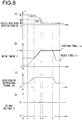
- Fig. 2 when the bucket 8 is inserted into the mound 12 at a time point "a" in Fig. 8 , a travel resistance increases as the bucket 8 enters deeper into the mound 12 at a constant vehicle body speed. A torque necessary for the electric motor 50 increases accordingly.
- the operator increases the amount of depression of the accelerator pedal (the accelerator pedal depressing signal AS) from the time point "a" as shown in Fig. 8(C) .
- the vehicle body speed (the rotation speed of the electric motor 50) can be maintained at a constant speed of N1 (refer to Fig. 8(A) ).
- the wheel loader travels at an approximately constant vehicle body speed (rotation speed N1) at the time points "a" and “b” in a diagram showing a torque-rotation speed relationship diagram in Fig. 6 .
- a travel resistance increases as the bucket 8 enters deeper into the mound 12 at a constant vehicle body speed.
- a torque necessary for the electric motor 50 increases accordingly.
- the request torque calculation unit 73 shown in Fig. 5 calculates a request torque ⁇ b from an accelerator pedal depressing signal AS.
- the request torque ⁇ b increases from the time point "a" as the accelerator pedal depressing signal AS increases.
- the outputtable torque calculation unit 74 calculates an outputtable torque ⁇ a by referring to a rotation speed N of the electric motor 50 and voltage V of the DC buses 80 and 81 to be detected by the voltage sensor 62. As shown in Fig. 6 , the outputtable torque ⁇ a decreases as the rotation speed N increases as indicated by the line 101, when it is not less than a certain vehicle body speed (the rotation speed N2 of the electric motor 50).
- the torque comparison unit 75 compares the request torque ⁇ b and the outputtable torque ⁇ a. It is however regarded that no torque increase request exists while the accelerator pedal depressing signal AS is small in a normal operation. Therefore, the torque comparison unit 75 performs no torque comparison while the accelerator pedal depressing signal AS ⁇ AS0 (threshold value) is not satisfied (step SP1 in Fig. 7 ).
- the threshold value AS0 is a predetermined value, based on which a determination is made as to whether or not to perform a comparison between the request torque ⁇ b and the outputtable torque ⁇ a by the torque comparison unit 75.
- the threshold value AS0 it is possible to use a value of the accelerator pedal depressing signal AS corresponding to at least approximately 50% of an amount of depression when the accelerator pedal is depressed at a maximum, preferably a value of the accelerator pedal depressing signal AS corresponding to approximately 75-85% of the amount of depression.
- the torque comparison unit 75 performs a torque comparison (step SP2), and makes a determination as to whether the request torque ⁇ b reaches the outputtable torque ⁇ a.
- the request torque ⁇ b is small and does not reach the outputtable torque ⁇ a ( ⁇ a > ⁇ b), and therefore the torque comparison unit 75 does not activate the DC bus voltage rise determination unit 76.
- step SP2 When the accelerator pedal depressing signal AS ⁇ AS0 and ⁇ b ⁇ ⁇ a are satisfied (step SP2) (the time point "b" in Fig. 9 ), the procedure proceeds to step SP3, and the DC bus voltage rise determination unit 76 is activated under conditions that the rotation speed N of the electric motor 50 is not less than the threshold value N0 (N ⁇ NO).
- N ⁇ NO the threshold value N0 of the rotation speed is set between the rotation speed N2 and the rotation speed N3 and in the vicinity of the rotation speed N2 in the torque-rotation speed characteristic diagram in Fig. 6 .
- Determinations in the DC bus voltage rise determination unit 76 are made as to whether the temperature T1 of the inverter 60 is not more than an upper limit value T10 and the temperature T2 of the electric motor 50 is not more than an upper limit value T20 (step SP4).
- the purpose of performing the following voltage rise processing only when the temperature of the inverter 60 and the temperature of the electric motor 50 do not exceed their respective upper limit temperatures is to protect the inverter 60 and the electric motor 50.
- the DC bus voltage rise determination unit 76 activates the voltage rise command unit 78, and the voltage rise command unit 78 sends a rise command signal Vs to the PC 43.
- the buck-boost converter 40 increases the DC bus voltage V from V1 to V2 on the basis of the command Vs, and maintains the DC bus voltage V in a state of being raised.
- the state in which the DC bus voltage is thus increased is limited to within time t0 being set to the timer unit 77, and is maintained provided that the temperatures T1 and T2 of the inverter 60 and the electric motor 50 do not exceed the upper limit values T10 and T20, respectively (steps SP7, SP8).
- the time t0 to be set by the timer unit 77 is necessary and sufficient time required for sufficiently inserting the bucket 8 into the mound 12 by traveling.
- the time t0 is preferably set to 4-14 seconds, more preferably approximately 8-12 seconds.
- the vehicle body speed decreases further as indicated by a line 107 in Fig. 9(A) in the state in which the request torque ⁇ b and the outputtable torque ⁇ a do not increase beyond the maximum value ⁇ max.
- the vehicle body speed decrease continues until the time point d' in Fig. 9 , at which a balance occurs between a travel resistance that is already decreased due to the vehicle body speed drop and a driving force of the vehicle body. Thereafter, the excavation is carried out at an approximately constant vehicle body speed.
- step SP9 when in steps SP1 to SP4, the accelerator depressing signal AS ⁇ AS0 (SP1), the request torque ⁇ b ⁇ the outputtable torque ⁇ a (SP2), the rotation speed N ⁇ N0 (SP3), the inverter temperature T1 > T10, or the electric motor temperature T2 > T20 (SP4) is satisfied.
- step SP9 a determination is made as to whether the DC bus voltage is in a high state. When the DC bus voltage is in the high state of V2, the DC bus voltage is returned to a normal voltage V1 (SP10). When the DC bus voltage is not in the high state of V2, processing is suspended while waiting for the next accelerator pedal depressing signal.
- the voltage V of the DC buses 80 and 81 is temporarily raised from V1 to V2. This contributes to temporarily increasing the outputtable torque ⁇ a of the electric motor 50, thereby ensuring that the wheel loader is operated without a drop of the rotation speed N of the electric motor 50. That is, raising the DC bus voltage V causes a speed difference in the electric motor 50 as indicated by a slanted line part 109 in Fig. 9(A) , thus making it possible to increase working efficiency than not raising the DC bus voltage V.
- the DC bus voltage V is raised only when the rotation speed N of the electric motor 50 is not less than the rotation speed N0 of the threshold value that requires the increase of the outputtable torque ⁇ a. It follows that the DC bus voltage V is raised only when it is really necessary to increase the outputtable torque ⁇ a, thus making it possible to perform stable control of the electric motor 50.
- the present invention is also applicable to other hybrid work machines besides the wheel loader, by performing the voltage control of the DC buses with respect to one in which the work machine is the wheel loader and the electric motor 50 is the travel motor as in the present embodiment, it is possible to smoothly insert the bucket into the mound and thereby improve excavation efficiency (working efficiency) even when the torque required for the travel motor is large as in the case of inserting the bucket 8 into the mound of earth and sand 12 which is an excavation object while causing the wheel loader to travel.
- the rear wheels 3 are driven by the electric motor 50
- it may be configured so that the front wheels 2 are driven by the electric motor 50.
- the present embodiment may be applied to a hybrid work machine with four-wheel drive configured to drive the front wheels 2 and the rear wheels 3.
- the request torque ⁇ b may be obtained from a speed command value and an acceleration command value at the electric motor 50, instead of obtaining it from an operation signal through a travel operation member.
- the request torque ⁇ b may be obtained from a deviation between the speed command value and a measured value of the electric motor 50, or a deviation between the acceleration command value and a measured value thereof.
- the voltage rise time needs to be held within a certain time range, and the voltage rise time may be a time period that varies depending on an operation state, instead of being set to be constant by the timer unit 77.
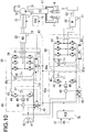
- FIG. 10 is a circuit diagram showing another embodiment in which DC buses of dual systems exist individually, without commonalizing DC buses into a single system, on the hydraulic electrical circuit of the work machine to which the present invention is applied.
- components having functions similar to the components of the hydraulic electrical circuit in Fig. 4 are identified by the same reference numerals.
- second DC buses 80a and 81a are separately disposed which are not common to first DC buses 80 and 81 to be connected to an inverter 30 as a first power converter.
- the second DC buses 80a and 81a and an inverter 60 as a second power converter are connected to one another.
- a second buck-boost converter 40a is also disposed which performs power transfer between both the second DC buses 80a and 81a and an electricity storage device 42. Similarly to the first buck-boost converter 40, the second buck-boost converter 40a performs power transfer between the electricity storage device 42 and both the second DC buses 80a and 81a.
- the voltage at the second DC buses 80a and 81a is temporarily raised when a torque required for an electric motor 50 exceeds a torque being outputtable at the voltage of the second DC buses 80a and 81 a to be connected to the inverter 60.
- Voltage rise control of the second DC buses 80a and 81a is basically similar to the voltage rise control of the first DC buses 80 and 81 in the foregoing embodiment.
- the another embodiment is capable of producing advantageous effects similar to those in the foregoing embodiment. Further in the another embodiment, the voltage at the second DC buses 80a and 81a, which are different from the first DC buses 80 and 81, is raised. Therefore, even when the inverter 60 temporarily generates heat due to voltage rise, the influence thereof is not exerted on equipment connected to the first DC buses 80 and 81. Furthermore, by disposing the DC buses of dual systems, the present invention is applicable to the case where the voltage of the first DC buses 80 and 81 is different from the voltage of the second DC buses 80a and 81a.
- the another embodiment has exemplified the example that the first buck-boost converter 40 is disposed between the electricity storage device 42 and the inverter 30 as shown in Fig. 10 , without limitation thereto, the electricity storage device 42 and the inverter 30 may be directly connected to each other without disposing the first buck-boost converter in case where a voltage range in which the electricity storage device 42 is used and an electricity storage device-side voltage range of the inverter 30 approximately match each other.
Landscapes
- Engineering & Computer Science (AREA)
- Power Engineering (AREA)
- Mining & Mineral Resources (AREA)
- Civil Engineering (AREA)
- General Engineering & Computer Science (AREA)
- Structural Engineering (AREA)
- Mechanical Engineering (AREA)
- Transportation (AREA)
- Combustion & Propulsion (AREA)
- Chemical & Material Sciences (AREA)
- Automation & Control Theory (AREA)
- Electric Propulsion And Braking For Vehicles (AREA)
- Operation Control Of Excavators (AREA)
- Hybrid Electric Vehicles (AREA)
Applications Claiming Priority (2)
| Application Number | Priority Date | Filing Date | Title |
|---|---|---|---|
| JP2014082371 | 2014-04-11 | ||
| PCT/JP2015/061116 WO2015156357A1 (ja) | 2014-04-11 | 2015-04-09 | ハイブリッド型作業機 |
Publications (3)
| Publication Number | Publication Date |
|---|---|
| EP3130708A1 true EP3130708A1 (de) | 2017-02-15 |
| EP3130708A4 EP3130708A4 (de) | 2017-11-29 |
| EP3130708B1 EP3130708B1 (de) | 2019-03-06 |
Family
ID=54287929
Family Applications (1)
| Application Number | Title | Priority Date | Filing Date |
|---|---|---|---|
| EP15776987.8A Not-in-force EP3130708B1 (de) | 2014-04-11 | 2015-04-09 | Hybride arbeitsmaschine mit gleichspannungssteuerung |
Country Status (6)
| Country | Link |
|---|---|
| US (1) | US10286894B2 (de) |
| EP (1) | EP3130708B1 (de) |
| JP (1) | JP6502324B2 (de) |
| KR (1) | KR101846107B1 (de) |
| CN (1) | CN106062287B (de) |
| WO (1) | WO2015156357A1 (de) |
Cited By (5)
| Publication number | Priority date | Publication date | Assignee | Title |
|---|---|---|---|---|
| DE102018203624A1 (de) | 2018-03-09 | 2019-09-12 | Zf Friedrichshafen Ag | Antrieb für eine Arbeitsmaschine |
| WO2019170344A1 (de) | 2018-03-09 | 2019-09-12 | Zf Friedrichshafen Ag | Antrieb für eine arbeitsmaschine |
| WO2019170343A1 (de) | 2018-03-09 | 2019-09-12 | Zf Friedrichshafen Ag | Antrieb für eine arbeitsmaschine |
| US10690705B2 (en) | 2016-06-15 | 2020-06-23 | Watlow Electric Manufacturing Company | Power converter for a thermal system |
| CN113765383A (zh) * | 2021-09-18 | 2021-12-07 | 珠海格力电器股份有限公司 | 一种升降压控制方法及处理器、关系搭建方法及处理器 |
Families Citing this family (7)
| Publication number | Priority date | Publication date | Assignee | Title |
|---|---|---|---|---|
| EP3574742B1 (de) * | 2017-01-25 | 2022-11-16 | Positec Power Tools (Suzhou) Co., Ltd | Rasenmäher |
| US11364811B1 (en) * | 2017-11-15 | 2022-06-21 | Motiv Power Systems, Inc. | Powering electric vehicle accessory devices from back EMF generated by an electric motor |
| CN109814404B (zh) * | 2019-01-22 | 2022-01-21 | 东风航盛(武汉)汽车控制系统有限公司 | 整车控制器的在环仿真标定系统及标定方法 |
| JP7405582B2 (ja) * | 2019-12-03 | 2023-12-26 | ナブテスコ株式会社 | 作用部用減速部及び建設機械 |
| CN114499283A (zh) * | 2020-10-26 | 2022-05-13 | 台达电子工业股份有限公司 | 发电机控制系统及其控制方法 |
| CN112942456B (zh) * | 2021-01-29 | 2022-07-29 | 上海三一重机股份有限公司 | 一种装载机动臂减震系统和作业机械 |
| CN114312353A (zh) * | 2021-12-31 | 2022-04-12 | 中国第一汽车股份有限公司 | 双电机电动汽车的扭矩控制系统、方法及双电机电动汽车 |
Family Cites Families (13)
| Publication number | Priority date | Publication date | Assignee | Title |
|---|---|---|---|---|
| JP3686476B2 (ja) * | 1996-06-13 | 2005-08-24 | コベルコ建機株式会社 | バッテリ駆動の作業機械 |
| JP3858654B2 (ja) * | 2001-09-28 | 2006-12-20 | 松下電器産業株式会社 | ガスレーザ発振装置 |
| JP2005009381A (ja) * | 2003-06-18 | 2005-01-13 | Hitachi Constr Mach Co Ltd | ハイブリッド式建設機械 |
| JP2005155862A (ja) * | 2003-11-28 | 2005-06-16 | Aisin Seiki Co Ltd | 複数の駆動源を備えた車両用変速制御装置 |
| US7378808B2 (en) * | 2004-05-25 | 2008-05-27 | Caterpillar Inc. | Electric drive system having DC bus voltage control |
| JP4949288B2 (ja) | 2008-02-12 | 2012-06-06 | 住友重機械工業株式会社 | ハイブリッド型建設機械 |
| JP5295727B2 (ja) * | 2008-11-14 | 2013-09-18 | 住友重機械工業株式会社 | ハイブリッド型作業機械 |
| JP5329574B2 (ja) * | 2011-01-25 | 2013-10-30 | 住友重機械工業株式会社 | ハイブリッド型建設機械 |
| JP5622693B2 (ja) * | 2011-09-09 | 2014-11-12 | 本田技研工業株式会社 | 燃料電池車両 |
| CN202544010U (zh) * | 2011-12-30 | 2012-11-21 | 杭州杭重工程机械有限公司 | 一种船用抓斗挖掘机的节能装置 |
| CN102535563A (zh) * | 2011-12-30 | 2012-07-04 | 杭州杭重工程机械有限公司 | 船用抓斗挖掘机的节能装置 |
| JP2013052866A (ja) * | 2012-10-24 | 2013-03-21 | Sumitomo Heavy Ind Ltd | ショベル及びその制御方法 |
| KR20150071629A (ko) * | 2013-12-18 | 2015-06-26 | 대우조선해양 주식회사 | 해양 플랜트의 하이브리드 전력 공급 장치 및 방법 |
-
2015
- 2015-04-09 WO PCT/JP2015/061116 patent/WO2015156357A1/ja not_active Ceased
- 2015-04-09 JP JP2016512774A patent/JP6502324B2/ja not_active Expired - Fee Related
- 2015-04-09 EP EP15776987.8A patent/EP3130708B1/de not_active Not-in-force
- 2015-04-09 KR KR1020167024210A patent/KR101846107B1/ko not_active Expired - Fee Related
- 2015-04-09 CN CN201580011777.0A patent/CN106062287B/zh not_active Expired - Fee Related
- 2015-04-09 US US15/122,240 patent/US10286894B2/en active Active
Cited By (10)
| Publication number | Priority date | Publication date | Assignee | Title |
|---|---|---|---|---|
| US10690705B2 (en) | 2016-06-15 | 2020-06-23 | Watlow Electric Manufacturing Company | Power converter for a thermal system |
| DE102018203624A1 (de) | 2018-03-09 | 2019-09-12 | Zf Friedrichshafen Ag | Antrieb für eine Arbeitsmaschine |
| WO2019170344A1 (de) | 2018-03-09 | 2019-09-12 | Zf Friedrichshafen Ag | Antrieb für eine arbeitsmaschine |
| WO2019170345A1 (de) | 2018-03-09 | 2019-09-12 | Zf Friedrichshafen Ag | Antrieb für eine arbeitsmaschine |
| WO2019170343A1 (de) | 2018-03-09 | 2019-09-12 | Zf Friedrichshafen Ag | Antrieb für eine arbeitsmaschine |
| DE102018203623A1 (de) | 2018-03-09 | 2019-09-12 | Zf Friedrichshafen Ag | Antrieb für eine Arbeitsmaschine |
| DE102018203622A1 (de) | 2018-03-09 | 2019-09-12 | Zf Friedrichshafen Ag | Antrieb für eine Arbeitsmaschine |
| US11761174B2 (en) | 2018-03-09 | 2023-09-19 | Zf Friedrichshafen Ag | Drive for a machine |
| US11905680B2 (en) | 2018-03-09 | 2024-02-20 | Zf Friedrichshafen Ag | Drive for a machine |
| CN113765383A (zh) * | 2021-09-18 | 2021-12-07 | 珠海格力电器股份有限公司 | 一种升降压控制方法及处理器、关系搭建方法及处理器 |
Also Published As
| Publication number | Publication date |
|---|---|
| KR101846107B1 (ko) | 2018-04-05 |
| JP6502324B2 (ja) | 2019-04-17 |
| CN106062287A (zh) | 2016-10-26 |
| US10286894B2 (en) | 2019-05-14 |
| JPWO2015156357A1 (ja) | 2017-04-13 |
| WO2015156357A1 (ja) | 2015-10-15 |
| US20160368472A1 (en) | 2016-12-22 |
| EP3130708A4 (de) | 2017-11-29 |
| EP3130708B1 (de) | 2019-03-06 |
| CN106062287B (zh) | 2018-06-22 |
| KR20160117557A (ko) | 2016-10-10 |
Similar Documents
| Publication | Publication Date | Title |
|---|---|---|
| EP3130708B1 (de) | Hybride arbeitsmaschine mit gleichspannungssteuerung | |
| US9000716B2 (en) | Hybrid working machine and electric power accumulation controller | |
| EP2228491B1 (de) | Hybridbaumaschine und steuerverfahren für eine hybridbaumaschine | |
| CN103620125B (zh) | 回转驱动装置 | |
| CN103187916B (zh) | 一种用于电动叉车的电机控制系统 | |
| EP3249116B1 (de) | Hybridbaumaschine | |
| CN105517837B (zh) | 作业机械 | |
| KR20140038841A (ko) | 소음 저감을 위한 친환경 자동차의 인버터 제어 방법 | |
| EP3805038A1 (de) | Wechselrichtersteuerungsverfahren und wechselrichtersteuersystem | |
| JP5917304B2 (ja) | ショベルの制御方法 | |
| EP3342940A1 (de) | Hybridbaumaschine | |
| EP2949821A1 (de) | Vorrichtung zur steuerung einer gleichstromklemmenspannung von baumaschinen mit einem motor und verfahren dafür | |
| CN108082178B (zh) | 混合动力汽车 | |
| CN110758367B (zh) | 用于制动系统检验的系统和方法 | |
| US20160264001A1 (en) | Vehicle control apparatus | |
| JP2016025725A (ja) | 電動車両 | |
| JP5786500B2 (ja) | 駆動装置 | |
| JP2010133238A (ja) | ハイブリッド型建設機械 | |
| US11673472B2 (en) | Apparatus and method for controlling a high voltage circuit | |
| JP5601761B2 (ja) | ハイブリッド型作業機械 | |
| JP2010133236A (ja) | ハイブリッド型建設機械 | |
| JP2013091453A (ja) | ハイブリッド車両のモータ制御装置 | |
| EP2918464A1 (de) | Hybridschaufel und hybridschaufelsteuerungsverfahren |
Legal Events
| Date | Code | Title | Description |
|---|---|---|---|
| STAA | Information on the status of an ep patent application or granted ep patent |
Free format text: STATUS: THE INTERNATIONAL PUBLICATION HAS BEEN MADE |
|
| PUAI | Public reference made under article 153(3) epc to a published international application that has entered the european phase |
Free format text: ORIGINAL CODE: 0009012 |
|
| STAA | Information on the status of an ep patent application or granted ep patent |
Free format text: STATUS: REQUEST FOR EXAMINATION WAS MADE |
|
| 17P | Request for examination filed |
Effective date: 20161111 |
|
| AK | Designated contracting states |
Kind code of ref document: A1 Designated state(s): AL AT BE BG CH CY CZ DE DK EE ES FI FR GB GR HR HU IE IS IT LI LT LU LV MC MK MT NL NO PL PT RO RS SE SI SK SM TR |
|
| AX | Request for extension of the european patent |
Extension state: BA ME |
|
| DAV | Request for validation of the european patent (deleted) | ||
| DAX | Request for extension of the european patent (deleted) | ||
| A4 | Supplementary search report drawn up and despatched |
Effective date: 20171103 |
|
| RIC1 | Information provided on ipc code assigned before grant |
Ipc: B60L 11/12 20060101ALI20171026BHEP Ipc: B60K 25/02 20060101ALI20171026BHEP Ipc: H02M 7/48 20070101ALI20171026BHEP Ipc: E02F 3/34 20060101ALI20171026BHEP Ipc: H02M 1/00 20060101ALI20171026BHEP Ipc: B60K 6/50 20071001ALI20171026BHEP Ipc: E02F 9/20 20060101AFI20171026BHEP Ipc: H02M 7/5387 20070101ALI20171026BHEP Ipc: B60W 20/10 20160101ALI20171026BHEP Ipc: H02M 3/155 20060101ALI20171026BHEP |
|
| RIC1 | Information provided on ipc code assigned before grant |
Ipc: H02M 7/48 20070101ALI20181011BHEP Ipc: B60W 20/10 20160101ALI20181011BHEP Ipc: B60K 6/46 20071001ALI20181011BHEP Ipc: H02M 7/5387 20070101ALI20181011BHEP Ipc: H02M 1/00 20060101ALI20181011BHEP Ipc: B60K 25/02 20060101ALI20181011BHEP Ipc: B60L 11/12 20060101ALI20181011BHEP Ipc: E02F 3/34 20060101ALI20181011BHEP Ipc: B60K 6/50 20071001ALI20181011BHEP Ipc: H02M 3/155 20060101ALI20181011BHEP Ipc: E02F 9/20 20060101AFI20181011BHEP |
|
| GRAP | Despatch of communication of intention to grant a patent |
Free format text: ORIGINAL CODE: EPIDOSNIGR1 |
|
| STAA | Information on the status of an ep patent application or granted ep patent |
Free format text: STATUS: GRANT OF PATENT IS INTENDED |
|
| INTG | Intention to grant announced |
Effective date: 20181127 |
|
| GRAS | Grant fee paid |
Free format text: ORIGINAL CODE: EPIDOSNIGR3 |
|
| GRAA | (expected) grant |
Free format text: ORIGINAL CODE: 0009210 |
|
| STAA | Information on the status of an ep patent application or granted ep patent |
Free format text: STATUS: THE PATENT HAS BEEN GRANTED |
|
| RIC1 | Information provided on ipc code assigned before grant |
Ipc: H02M 3/155 20060101ALI20181011BHEP Ipc: B60K 6/46 20071001ALI20181011BHEP Ipc: E02F 3/34 20060101ALI20181011BHEP Ipc: E02F 9/20 20060101AFI20181011BHEP Ipc: H02M 7/48 20070101ALI20181011BHEP Ipc: H02M 7/5387 20070101ALI20181011BHEP Ipc: B60W 20/10 20160101ALI20181011BHEP Ipc: B60K 6/50 20071001ALI20181011BHEP Ipc: B60L 11/12 20060101ALI20181011BHEP Ipc: H02M 1/00 20060101ALI20181011BHEP Ipc: B60K 25/02 20060101ALI20181011BHEP |
|
| RIN1 | Information on inventor provided before grant (corrected) |
Inventor name: SEKINE, KAZUYA Inventor name: TAKADA, TOMONORI Inventor name: HIGURASHI, MASAKI Inventor name: IKIMI, TAKASHI |
|
| AK | Designated contracting states |
Kind code of ref document: B1 Designated state(s): AL AT BE BG CH CY CZ DE DK EE ES FI FR GB GR HR HU IE IS IT LI LT LU LV MC MK MT NL NO PL PT RO RS SE SI SK SM TR |
|
| REG | Reference to a national code |
Ref country code: GB Ref legal event code: FG4D |
|
| REG | Reference to a national code |
Ref country code: CH Ref legal event code: EP Ref country code: AT Ref legal event code: REF Ref document number: 1104751 Country of ref document: AT Kind code of ref document: T Effective date: 20190315 |
|
| REG | Reference to a national code |
Ref country code: DE Ref legal event code: R096 Ref document number: 602015025950 Country of ref document: DE |
|
| REG | Reference to a national code |
Ref country code: IE Ref legal event code: FG4D |
|
| REG | Reference to a national code |
Ref country code: SE Ref legal event code: TRGR |
|
| REG | Reference to a national code |
Ref country code: NL Ref legal event code: MP Effective date: 20190306 |
|
| REG | Reference to a national code |
Ref country code: LT Ref legal event code: MG4D |
|
| PG25 | Lapsed in a contracting state [announced via postgrant information from national office to epo] |
Ref country code: LT Free format text: LAPSE BECAUSE OF FAILURE TO SUBMIT A TRANSLATION OF THE DESCRIPTION OR TO PAY THE FEE WITHIN THE PRESCRIBED TIME-LIMIT Effective date: 20190306 Ref country code: NO Free format text: LAPSE BECAUSE OF FAILURE TO SUBMIT A TRANSLATION OF THE DESCRIPTION OR TO PAY THE FEE WITHIN THE PRESCRIBED TIME-LIMIT Effective date: 20190606 Ref country code: FI Free format text: LAPSE BECAUSE OF FAILURE TO SUBMIT A TRANSLATION OF THE DESCRIPTION OR TO PAY THE FEE WITHIN THE PRESCRIBED TIME-LIMIT Effective date: 20190306 |
|
| REG | Reference to a national code |
Ref country code: DE Ref legal event code: R082 Ref document number: 602015025950 Country of ref document: DE Representative=s name: MERH-IP MATIAS ERNY REICHL HOFFMANN PATENTANWA, DE Ref country code: DE Ref legal event code: R081 Ref document number: 602015025950 Country of ref document: DE Owner name: HITACHI CONSTRUCTION MACHINERY CO., LTD., JP Free format text: FORMER OWNER: KCM CORP., KAKO-GUN, HYOGO, JP |
|
| PG25 | Lapsed in a contracting state [announced via postgrant information from national office to epo] |
Ref country code: RS Free format text: LAPSE BECAUSE OF FAILURE TO SUBMIT A TRANSLATION OF THE DESCRIPTION OR TO PAY THE FEE WITHIN THE PRESCRIBED TIME-LIMIT Effective date: 20190306 Ref country code: HR Free format text: LAPSE BECAUSE OF FAILURE TO SUBMIT A TRANSLATION OF THE DESCRIPTION OR TO PAY THE FEE WITHIN THE PRESCRIBED TIME-LIMIT Effective date: 20190306 Ref country code: NL Free format text: LAPSE BECAUSE OF FAILURE TO SUBMIT A TRANSLATION OF THE DESCRIPTION OR TO PAY THE FEE WITHIN THE PRESCRIBED TIME-LIMIT Effective date: 20190306 Ref country code: LV Free format text: LAPSE BECAUSE OF FAILURE TO SUBMIT A TRANSLATION OF THE DESCRIPTION OR TO PAY THE FEE WITHIN THE PRESCRIBED TIME-LIMIT Effective date: 20190306 Ref country code: BG Free format text: LAPSE BECAUSE OF FAILURE TO SUBMIT A TRANSLATION OF THE DESCRIPTION OR TO PAY THE FEE WITHIN THE PRESCRIBED TIME-LIMIT Effective date: 20190606 Ref country code: GR Free format text: LAPSE BECAUSE OF FAILURE TO SUBMIT A TRANSLATION OF THE DESCRIPTION OR TO PAY THE FEE WITHIN THE PRESCRIBED TIME-LIMIT Effective date: 20190607 |
|
| REG | Reference to a national code |
Ref country code: AT Ref legal event code: MK05 Ref document number: 1104751 Country of ref document: AT Kind code of ref document: T Effective date: 20190306 |
|
| PG25 | Lapsed in a contracting state [announced via postgrant information from national office to epo] |
Ref country code: EE Free format text: LAPSE BECAUSE OF FAILURE TO SUBMIT A TRANSLATION OF THE DESCRIPTION OR TO PAY THE FEE WITHIN THE PRESCRIBED TIME-LIMIT Effective date: 20190306 Ref country code: PT Free format text: LAPSE BECAUSE OF FAILURE TO SUBMIT A TRANSLATION OF THE DESCRIPTION OR TO PAY THE FEE WITHIN THE PRESCRIBED TIME-LIMIT Effective date: 20190706 Ref country code: SK Free format text: LAPSE BECAUSE OF FAILURE TO SUBMIT A TRANSLATION OF THE DESCRIPTION OR TO PAY THE FEE WITHIN THE PRESCRIBED TIME-LIMIT Effective date: 20190306 Ref country code: AL Free format text: LAPSE BECAUSE OF FAILURE TO SUBMIT A TRANSLATION OF THE DESCRIPTION OR TO PAY THE FEE WITHIN THE PRESCRIBED TIME-LIMIT Effective date: 20190306 Ref country code: ES Free format text: LAPSE BECAUSE OF FAILURE TO SUBMIT A TRANSLATION OF THE DESCRIPTION OR TO PAY THE FEE WITHIN THE PRESCRIBED TIME-LIMIT Effective date: 20190306 Ref country code: RO Free format text: LAPSE BECAUSE OF FAILURE TO SUBMIT A TRANSLATION OF THE DESCRIPTION OR TO PAY THE FEE WITHIN THE PRESCRIBED TIME-LIMIT Effective date: 20190306 Ref country code: IT Free format text: LAPSE BECAUSE OF FAILURE TO SUBMIT A TRANSLATION OF THE DESCRIPTION OR TO PAY THE FEE WITHIN THE PRESCRIBED TIME-LIMIT Effective date: 20190306 Ref country code: CZ Free format text: LAPSE BECAUSE OF FAILURE TO SUBMIT A TRANSLATION OF THE DESCRIPTION OR TO PAY THE FEE WITHIN THE PRESCRIBED TIME-LIMIT Effective date: 20190306 |
|
| PG25 | Lapsed in a contracting state [announced via postgrant information from national office to epo] |
Ref country code: SM Free format text: LAPSE BECAUSE OF FAILURE TO SUBMIT A TRANSLATION OF THE DESCRIPTION OR TO PAY THE FEE WITHIN THE PRESCRIBED TIME-LIMIT Effective date: 20190306 Ref country code: PL Free format text: LAPSE BECAUSE OF FAILURE TO SUBMIT A TRANSLATION OF THE DESCRIPTION OR TO PAY THE FEE WITHIN THE PRESCRIBED TIME-LIMIT Effective date: 20190306 |
|
| REG | Reference to a national code |
Ref country code: CH Ref legal event code: PL |
|
| REG | Reference to a national code |
Ref country code: DE Ref legal event code: R097 Ref document number: 602015025950 Country of ref document: DE |
|
| REG | Reference to a national code |
Ref country code: BE Ref legal event code: MM Effective date: 20190430 |
|
| PG25 | Lapsed in a contracting state [announced via postgrant information from national office to epo] |
Ref country code: AT Free format text: LAPSE BECAUSE OF FAILURE TO SUBMIT A TRANSLATION OF THE DESCRIPTION OR TO PAY THE FEE WITHIN THE PRESCRIBED TIME-LIMIT Effective date: 20190306 Ref country code: LU Free format text: LAPSE BECAUSE OF NON-PAYMENT OF DUE FEES Effective date: 20190409 Ref country code: IS Free format text: LAPSE BECAUSE OF FAILURE TO SUBMIT A TRANSLATION OF THE DESCRIPTION OR TO PAY THE FEE WITHIN THE PRESCRIBED TIME-LIMIT Effective date: 20190706 |
|
| PLBE | No opposition filed within time limit |
Free format text: ORIGINAL CODE: 0009261 |
|
| STAA | Information on the status of an ep patent application or granted ep patent |
Free format text: STATUS: NO OPPOSITION FILED WITHIN TIME LIMIT |
|
| PG25 | Lapsed in a contracting state [announced via postgrant information from national office to epo] |
Ref country code: CH Free format text: LAPSE BECAUSE OF NON-PAYMENT OF DUE FEES Effective date: 20190430 Ref country code: DK Free format text: LAPSE BECAUSE OF FAILURE TO SUBMIT A TRANSLATION OF THE DESCRIPTION OR TO PAY THE FEE WITHIN THE PRESCRIBED TIME-LIMIT Effective date: 20190306 Ref country code: LI Free format text: LAPSE BECAUSE OF NON-PAYMENT OF DUE FEES Effective date: 20190430 Ref country code: MC Free format text: LAPSE BECAUSE OF FAILURE TO SUBMIT A TRANSLATION OF THE DESCRIPTION OR TO PAY THE FEE WITHIN THE PRESCRIBED TIME-LIMIT Effective date: 20190306 |
|
| 26N | No opposition filed |
Effective date: 20191209 |
|
| GBPC | Gb: european patent ceased through non-payment of renewal fee |
Effective date: 20190606 |
|
| PG25 | Lapsed in a contracting state [announced via postgrant information from national office to epo] |
Ref country code: BE Free format text: LAPSE BECAUSE OF NON-PAYMENT OF DUE FEES Effective date: 20190430 Ref country code: SI Free format text: LAPSE BECAUSE OF FAILURE TO SUBMIT A TRANSLATION OF THE DESCRIPTION OR TO PAY THE FEE WITHIN THE PRESCRIBED TIME-LIMIT Effective date: 20190306 |
|
| PG25 | Lapsed in a contracting state [announced via postgrant information from national office to epo] |
Ref country code: TR Free format text: LAPSE BECAUSE OF FAILURE TO SUBMIT A TRANSLATION OF THE DESCRIPTION OR TO PAY THE FEE WITHIN THE PRESCRIBED TIME-LIMIT Effective date: 20190306 |
|
| PG25 | Lapsed in a contracting state [announced via postgrant information from national office to epo] |
Ref country code: IE Free format text: LAPSE BECAUSE OF NON-PAYMENT OF DUE FEES Effective date: 20190409 Ref country code: GB Free format text: LAPSE BECAUSE OF NON-PAYMENT OF DUE FEES Effective date: 20190606 |
|
| PG25 | Lapsed in a contracting state [announced via postgrant information from national office to epo] |
Ref country code: FR Free format text: LAPSE BECAUSE OF NON-PAYMENT OF DUE FEES Effective date: 20190506 |
|
| PG25 | Lapsed in a contracting state [announced via postgrant information from national office to epo] |
Ref country code: CY Free format text: LAPSE BECAUSE OF FAILURE TO SUBMIT A TRANSLATION OF THE DESCRIPTION OR TO PAY THE FEE WITHIN THE PRESCRIBED TIME-LIMIT Effective date: 20190306 |
|
| PG25 | Lapsed in a contracting state [announced via postgrant information from national office to epo] |
Ref country code: HU Free format text: LAPSE BECAUSE OF FAILURE TO SUBMIT A TRANSLATION OF THE DESCRIPTION OR TO PAY THE FEE WITHIN THE PRESCRIBED TIME-LIMIT; INVALID AB INITIO Effective date: 20150409 Ref country code: MT Free format text: LAPSE BECAUSE OF FAILURE TO SUBMIT A TRANSLATION OF THE DESCRIPTION OR TO PAY THE FEE WITHIN THE PRESCRIBED TIME-LIMIT Effective date: 20190306 |
|
| PG25 | Lapsed in a contracting state [announced via postgrant information from national office to epo] |
Ref country code: MK Free format text: LAPSE BECAUSE OF FAILURE TO SUBMIT A TRANSLATION OF THE DESCRIPTION OR TO PAY THE FEE WITHIN THE PRESCRIBED TIME-LIMIT Effective date: 20190306 |
|
| PGFP | Annual fee paid to national office [announced via postgrant information from national office to epo] |
Ref country code: DE Payment date: 20230228 Year of fee payment: 9 |
|
| PGFP | Annual fee paid to national office [announced via postgrant information from national office to epo] |
Ref country code: SE Payment date: 20240312 Year of fee payment: 10 |
|
| REG | Reference to a national code |
Ref country code: DE Ref legal event code: R119 Ref document number: 602015025950 Country of ref document: DE |
|
| REG | Reference to a national code |
Ref country code: SE Ref legal event code: EUG |
|
| PG25 | Lapsed in a contracting state [announced via postgrant information from national office to epo] |
Ref country code: DE Free format text: LAPSE BECAUSE OF NON-PAYMENT OF DUE FEES Effective date: 20251104 |
|
| PG25 | Lapsed in a contracting state [announced via postgrant information from national office to epo] |
Ref country code: SE Free format text: LAPSE BECAUSE OF NON-PAYMENT OF DUE FEES Effective date: 20250410 |