EP3130736B1 - Ensemble comprenant une porte automatique, telle qu'une porte coulissante, une porte rotative ou similaire, et un dispositif de signalisation, par exemple une centrale d'alarme incendie ou un détecteur de fumée - Google Patents
Ensemble comprenant une porte automatique, telle qu'une porte coulissante, une porte rotative ou similaire, et un dispositif de signalisation, par exemple une centrale d'alarme incendie ou un détecteur de fumée Download PDFInfo
- Publication number
- EP3130736B1 EP3130736B1 EP16183535.0A EP16183535A EP3130736B1 EP 3130736 B1 EP3130736 B1 EP 3130736B1 EP 16183535 A EP16183535 A EP 16183535A EP 3130736 B1 EP3130736 B1 EP 3130736B1
- Authority
- EP
- European Patent Office
- Prior art keywords
- door
- control
- automatic door
- additional control
- closing movement
- Prior art date
- Legal status (The legal status is an assumption and is not a legal conclusion. Google has not performed a legal analysis and makes no representation as to the accuracy of the status listed.)
- Active
Links
Images


Classifications
-
- E—FIXED CONSTRUCTIONS
- E05—LOCKS; KEYS; WINDOW OR DOOR FITTINGS; SAFES
- E05F—DEVICES FOR MOVING WINGS INTO OPEN OR CLOSED POSITION; CHECKS FOR WINGS; WING FITTINGS NOT OTHERWISE PROVIDED FOR, CONCERNED WITH THE FUNCTIONING OF THE WING
- E05F15/00—Power-operated mechanisms for wings
- E05F15/70—Power-operated mechanisms for wings with automatic actuation
- E05F15/72—Power-operated mechanisms for wings with automatic actuation responsive to emergency conditions, e.g. fire
-
- E—FIXED CONSTRUCTIONS
- E05—LOCKS; KEYS; WINDOW OR DOOR FITTINGS; SAFES
- E05F—DEVICES FOR MOVING WINGS INTO OPEN OR CLOSED POSITION; CHECKS FOR WINGS; WING FITTINGS NOT OTHERWISE PROVIDED FOR, CONCERNED WITH THE FUNCTIONING OF THE WING
- E05F15/00—Power-operated mechanisms for wings
- E05F15/70—Power-operated mechanisms for wings with automatic actuation
- E05F15/73—Power-operated mechanisms for wings with automatic actuation responsive to movement or presence of persons or objects
-
- E—FIXED CONSTRUCTIONS
- E05—LOCKS; KEYS; WINDOW OR DOOR FITTINGS; SAFES
- E05Y—INDEXING SCHEME ASSOCIATED WITH SUBCLASSES E05D AND E05F, RELATING TO CONSTRUCTION ELEMENTS, ELECTRIC CONTROL, POWER SUPPLY, POWER SIGNAL OR TRANSMISSION, USER INTERFACES, MOUNTING OR COUPLING, DETAILS, ACCESSORIES, AUXILIARY OPERATIONS NOT OTHERWISE PROVIDED FOR, APPLICATION THEREOF
- E05Y2400/00—Electronic control; Electrical power; Power supply; Power or signal transmission; User interfaces
- E05Y2400/10—Electronic control
- E05Y2400/40—Control units therefor
-
- E—FIXED CONSTRUCTIONS
- E05—LOCKS; KEYS; WINDOW OR DOOR FITTINGS; SAFES
- E05Y—INDEXING SCHEME ASSOCIATED WITH SUBCLASSES E05D AND E05F, RELATING TO CONSTRUCTION ELEMENTS, ELECTRIC CONTROL, POWER SUPPLY, POWER SIGNAL OR TRANSMISSION, USER INTERFACES, MOUNTING OR COUPLING, DETAILS, ACCESSORIES, AUXILIARY OPERATIONS NOT OTHERWISE PROVIDED FOR, APPLICATION THEREOF
- E05Y2900/00—Application of doors, windows, wings or fittings thereof
- E05Y2900/10—Application of doors, windows, wings or fittings thereof for buildings or parts thereof
- E05Y2900/13—Type of wing
- E05Y2900/132—Doors
Definitions
- the invention relates to a set comprising an automatic door, such as a sliding door, a revolving door or the like, and a signaling device, for example a fire alarm control panel or a smoke detector, the automatic door comprising at least one door leaf which can be driven by means of a control via a drive device, and wherein presence sensors are provided on the inside and/or outside of the automatic door for monitoring the passage area of the door.
- an automatic door such as a sliding door, a revolving door or the like
- a signaling device for example a fire alarm control panel or a smoke detector
- the automatic door comprising at least one door leaf which can be driven by means of a control via a drive device, and wherein presence sensors are provided on the inside and/or outside of the automatic door for monitoring the passage area of the door.
- the closing movement is secured by presence sensors that are mounted inside and outside the sliding door system.
- the function of the sensors is checked during each closing phase, with the presence sensors monitoring the entire passage through the door. If an object is detected during the closing movement, the sliding door opens immediately.
- the mains voltage used to operate the sliding door system is constantly monitored by the control system. If the mains voltage fails, the system automatically switches to battery voltage. The energy stored in the battery can still be used to move the sliding door, e.g. the door can be closed and locked.
- the sliding door can optionally be opened using the button in the event of a power failure.
- Such a sliding door system is, for example, from the DE 10 2006 020 372 B4
- a sliding door system with at least one sliding door leaf is described, which can be driven by means of a drive device controlled by an electrical control device.
- the door system is Can be used as an escape and rescue route, as the drive device is designed in such a way that the sliding door leaf is opened when an emergency signal is received to clear an escape route and the sliding door system can be locked by a locking device at least in one operating state.
- An unlocking device is provided for unlocking the locking device.
- Another door system is from the DE 10 2010 002 870 A1 known, whereby this sliding door system also has a release for opening an escape and rescue route.
- DE 10 2010 024 755 A1 which also provides the function of an escape route door, by means of which a person can operate the door drive during fault operation in order to carry out an opening or closing cycle of the sliding door leaf from the closed position indicated by the fire protection function device.
- the invention therefore addresses the problem of providing a door control for an automatic door such as a sliding door, a revolving door or the like, which fulfils the function of a self-closing closure, e.g. a fire protection sliding door or a fire protection, without having to provide provisions and applications for the actual automatic door operation.
- a self-closing closure e.g. a fire protection sliding door or a fire protection
- the additional control initiates the closing movement immediately when a signal from the signaling device is received, e.g. in the event of a fire, regardless of the door program set on the door control.
- the additional control disconnects the drive train, i.e. the motor cables or one or two drive trains are electrically disconnected from the door control of the basic control.
- the additional control switches over to itself so that the additional control and not the basic control of the door control is electrically connected to the drive train.
- communication can also take place between the so-called basic control and the additional control in order to provide components for a redundantly designed control of the additional control.
- the additional control can close the door in the phase of the signal taking into account optional safety sensors connected to the additional control, such as closing area monitoring, presence sensors or even by ignoring them.
- the additional control closing the automatic door at a low speed and with load shutdown by motor current.
- the low speed must be selected so that a risk can be ruled out by standards. If the closing movement takes place while evaluating the safety sensors optionally connected to the additional control, the door can be moved at normal speed. If the presence sensors are triggered in this closing phase, the door immediately stops. If the safety sensors optionally connected to the additional control are occupied for a longer period of time in this phase, the signal is ignored by the control and the door continues to close at a low speed as described above.
- the automatic door then locks in the closed position using a locking mechanism that can be controlled and/or switched by the additional control system, whereby the locking mechanism prevents the automatic door from being pushed open in at least one position up to the entire area of the door. Attempts to open the door using the door control system are prevented by separating the drive units.
- the automatic door will drive towards the obstacle.
- the additional control is designed in such a way that the automatic door closes cyclically and the door then tries to end the closing process.
- the automatic door can only be reset or restarted using the additional control when the emergency closing signal is no longer triggered, so that manual operation of the program switch and/or other switching elements can only then be carried out.
- the drive stops If an obstacle is detected during the closing movement by defective safety sensors optionally connected to the additional control, such as closing area monitoring and presence sensors, the drive stops.
- the closing process is automatically restarted after a time delay. After, for example, five failed attempts, the drive stops at the obstacle and switches off. The number of failed attempts can be changed. However, if a fire alarm occurs, attempts to close will continue cyclically.
- this signal is indicated optically and/or acoustically by the additional control after a time x. If a signal is received from the signaling device during this time, e.g. a fire alarm, the additional control closes the door at a reduced speed. This speed ensures that there is no danger to people. The sliding door is automatically locked after reaching the closed position and the additional control switches off. Renewed operation is only possible when the user consciously starts the additional control again and the additional control does not detect any error in the system.
- a critical error would be, for example, a failure or error in the main computer or a failure or error in the main drive. This situation would result in the closing movement being carried out via the main drive or the emergency drive if possible. If the safety sensors optionally connected to the additional control cannot be evaluated, the automatic door is closed at a reduced speed. This reduced speed is selected so that there is no danger to people. The automatic sliding door is locked after the closed position is reached and the additional control switches off. Renewed operation is only possible when the user consciously starts the door again and the door does not detect any error in the system.
- an additional control is provided for controlling the door as a basic control, which is connected to a signaling device, for example to a fire alarm control panel or a smoke detector, and which, independently of the basic control, immediately triggers the closing movement when the signaling device receives a signal.
- the additional control on the automatic door is connected to a signaling device, for example to a fire alarm control panel or a smoke detector, whereby a control evaluates the signal from the signaling device via a main computer and a control computer, which, regardless of the set and programmed state of the basic control of the automatic door, causes the immediate closing movement of the door leaf or leaves via the control, in order to provide the automatic door as a fire protection door or fire barrier, unless the communication and monitoring of the Movement of the door control ensures that the additional control system closes the door. This is ensured by separating and switching the drive train from the door control.
- the automatic door which has been extended by the additional control, can also be used as a fire protection sliding door or fire protection.
- the automatic door does not need to be equipped with mechanical means such as a spring accumulator or a weight accumulator, for example, to create a fire barrier in the event of a fire. In the automatic door according to the invention, this is provided by the additional electronic control.
- the closing movement takes place at low speed and with load switching off.
- the automatic door locks automatically when closed.
- the additional control of the automatic door causes a cyclical closing movement in the event of an obstacle in the passage area. If the obstacle remains in the passage area, the door switches off. Opening by the door control is prevented, however.
- the automatic door closes via a redundant path to close the door. This ensures that if, for example, the power supply or the drive unit or the controls fail completely in the event of a fire, the shutdown still occurs.
- an error is indicated visually if the control system fails.
- the automatic door can only be restarted if there is no fire alarm. When the automatic door is restarted, this can only be done by manually operating the additional control system. If it is necessary to open the safety door, it is still possible to open it manually, although in the event of a fire the control system always provides a closing mechanism.
- Another particularly advantageous embodiment of the invention ensures the reliability of the closure in that, via safety-relevant communication between the basic control and the additional control, part of the redundancy is on the additional control and a second part is on the basic control. This means that a closure or a fire protection closure can be achieved with little component effort. This also applies if the basic control or additional control is subject to a critical error.
- the status of the error message can be displayed visually and/or acoustically.
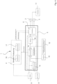
- the Figure 1 shows a door control 1 for an automatic door, such as a sliding door, a revolving door or the like.
- This comprises at least one door leaf, which is driven by a motor 2 and/or a motor 3.
- the door control 1 comprises a basic control 4 and an additional control 5, both of which are connected to the motors 2, 3 via a switch 6.
- the switch 6 is in the Figure 3 and in the Figure 5 presented in more detail here.
- the basic control 4 normally drives the automatic door unless the switch 6 is operated by a redundant system 7 of the additional control 5.
- a power supply 9, a battery 8 and a trigger 10 such as a fire alarm are connected to the redundant system 7.
- the redundant system 7 is operatively connected to the switch 6 and is thus connected to the motors 2, 3 and the locking mechanism 11.
- a closing area monitoring system 12 can be connected to the redundant system 7.
- the motors 2, 3 are separated from the basic control 4 of the door control 1 by means of the switch 6 and switched to the additional control 5 according to the invention.
- the additional control 5 immediately causes the closing movement of the door leaf or leaves in order to use the automatic door 1 as a fire door or as a fire barrier.
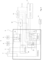
- the Figure 2 shows the additional control 5 and here in particular the redundant system 7 in more detail for an automatic door, such as a sliding door, a revolving door or the like.
- This comprises at least one door leaf which is driven by a motor 2, 3.
- the door control 1 is connected to the motors 2, 3 via the switch 6 and can normally drive them unless the redundant system 7, consisting of a battery charge 13, a control computer 14 and a motor control 15, does not operate the switch 10.
- the system 7 consists of a main computer 16 and a control computer 14, which monitor each other and thus operate the redundant motor control 15 consisting of the motor output stage 17 and the emergency stage 18 and which operate the switch 6.
- the system 7 is supplied by the power supply 9 or the battery 8, so that a permanent supply is guaranteed.
- the trigger 10, via which the signal is received, is directly connected to the system 7 and thus to the main computer 16 and the control computer 14.
- An optional additional closing area monitor 12 is also connected to the system 7.
- the motor control 15 consists, as already mentioned, of the motor output stage 17 and the emergency stage 18, which are supplied by the power pack 9 or the battery 8. The supply is connected to the motors 2, 3 via the switch 6.
- the motor(s) 2, 3 can still drive the motor(s) 2, 3 even if a component, for example the motor output stage 17, fails, so that a safe closure is possible.
- the locking mechanism 11 is connected to the switch 6 so that it can be controlled by the additional control 5.
- the motors 2, 3 of the door control 1 are separated from the basic control 4 by the switch 6 and switched to the additional control 5 according to the invention.
- the additional control 5 will then immediately cause the closing movement of the door leaf or leaves, taking into account the closing area monitoring 12, in order to use the automatic door 1 as a fire door or as a fire barrier to ensure closure.
- the main computer 16 and/or the control computer 14 are controlled so that the signal for the motor output stage 17 or an emergency stage 18 is passed on to start up the motors 2, 3.
- the Figure 3 shows, by way of example, the switch 6 contained in the additional control 5 according to the invention.
- the switch 6 consists of a voltage switch 19, a motor switch 20, a locking switch 21 and a motor control switch 22, which is operatively connected to the system 7 of the basic control 4, the motors 2, 3, the motor control 15 and the battery 8 and the locking.
- the battery 8 and the power supply 9 can be switched from the system 7 to the motor control 15 via the voltage switch 19. This ensures that the motor control 15 is always supplied with voltage If the basic control 4 of the standard door control is separated from the motor(s) 2, 3 via the motor control switch 22 and the system 7, the redundantly supplied motor control 15 can drive the motors 2, 3 to close.
- the motor control switch 22 enables the system 7 to select one of the two or both motors 2, 3 to close the door, so that if one of the two motors 2 or 3 is defective, it is guaranteed that the door will still close.
- the Figure 4 and 5 show a further embodiment of the door control 1 consisting of the basic control 4 and the additional control 5, whereby there is the possibility of communication between the additional control 5 and the basic control 4 in order to ensure the redundancy of the additional control 5.
- the advantage of this embodiment is that components such as the main computer 16 and the motor output stage 17 can be saved.
- the Figures 4 and 5 The embodiment described and shown behaves in such a way that when the trigger 10 is activated as a result of a signal, a closing command is given by the additional control 5 via the communication of the basic control 4. This closing movement is monitored by the additional control 5. If it is determined that no closing is carried out by the basic control 4, the motors 2, 3 are separated from the basic control 4 of the door control 1 by means of the switch 6 and switched to the additional control 5 according to the invention. The additional control 5 immediately causes the closing movement of the door leaf or leaves in order to use the automatic door 1 as a fire door or as a fire barrier.
Landscapes
- Business, Economics & Management (AREA)
- Emergency Management (AREA)
- Power-Operated Mechanisms For Wings (AREA)
- Special Wing (AREA)
Claims (8)
- Ensemble, comprenant une porte automatique, comme par exemple une porte coulissante, une porte pivotante ou de ce type, et un système de signalisation, par exemple une centrale d'alerte incendie ou un détecteur de fumée, la porte automatique comprenant au moins un battant de porte, qui peut être entraîné au moyen d'une commande (1) par un système d'entraînement et sachant que sur la zone intérieure et/ou extérieure de la porte automatique des capteurs de présence (12) sont prévus pour la surveillance de la zone de passage de la porte, sachant que la porte automatique dispose en plus d'une commande de base (4) d'une commande auxiliaire (5), qui est reliée au système de signalisation et qui déclenche immédiatement la course de fermeture lors d'un signal du système de signalisation indépendamment de la commande de base (4), sachant que la commande auxiliaire (5) reste en liaison fonctionnelle avec le système d'entraînement en cas de déclenchement de signal
caractérisé en ce que
la commande auxiliaire (5) dispose en tant que platine supplémentaire d'un calculateur principal (16) et d'un calculateur de contrôle (14), qui cause par le biais de la commande auxiliaire (5) directement le mouvement de fermeture du ou des battant(s) de porte en cas d'urgence par exemple en tant que fermeture pour incendie indépendamment de l'état réglé et programmé de la commande de base (4) pour la porte automatique - Porte automatique selon la revendication 1,
caractérisée en ce qu'
il existe une communication entre la commande de base (4) et la commande auxiliaire (5). - Porte automatique selon la revendication 1 à 2, caractérisée en ce que
la commande auxiliaire (5) poursuit le mouvement de fermeture en cas d'exigence quelconque par le système de signalisation et en tenant compte des capteurs de présence avec une vitesse normale ou en cas d'occupation permanente avec une vitesse faible. - Porte automatique selon la revendication 3,
caractérisée en ce que
le mouvement de fermeture sans les capteurs de présence (12) peut avoir lieu à faible vitesse. - Porte automatique selon la revendication 4,
caractérisée en ce que
le mouvement de fermeture a lieu en délestage de charge. - Porte automatique selon les revendications 1 à 5,
caractérisée en ce que
la commande auxiliaire (5), après le mouvement de fermeture de la porte verrouille celle-ci à l'état fermé automatiquement de façon mécanique ou électrique. - Porte automatique selon les revendications 1 à 6,
caractérisée en ce que
la commande auxiliaire (5) déclenche des marches de fermeture cycliques en cas d'obstacle dans la zone de passage. - Porte automatique selon les revendications 1 à 7,
caractérisée en ce qu'
en cas de panne de la commande auxiliaire (5) ou en cas d'erreur dans le calculateur principal (16), le calculateur de contrôle (14), dans la phase finale de secours (18) ou en cas d'une erreur dans l'entraînement principal, le mouvement de fermeture de la porte automatique a lieu par le biais par exemple d'une branche de courant de secours alimentée par un accumulateur d'énergie électrique avec une batterie (13) .
Applications Claiming Priority (1)
| Application Number | Priority Date | Filing Date | Title |
|---|---|---|---|
| DE102015113228.1A DE102015113228A1 (de) | 2015-08-11 | 2015-08-11 | Automatiktür, wie beispielsweise eine Schiebetür, eine Drehtür oder dergleichen |
Publications (2)
| Publication Number | Publication Date |
|---|---|
| EP3130736A1 EP3130736A1 (fr) | 2017-02-15 |
| EP3130736B1 true EP3130736B1 (fr) | 2024-10-02 |
Family
ID=56618067
Family Applications (1)
| Application Number | Title | Priority Date | Filing Date |
|---|---|---|---|
| EP16183535.0A Active EP3130736B1 (fr) | 2015-08-11 | 2016-08-10 | Ensemble comprenant une porte automatique, telle qu'une porte coulissante, une porte rotative ou similaire, et un dispositif de signalisation, par exemple une centrale d'alarme incendie ou un détecteur de fumée |
Country Status (2)
| Country | Link |
|---|---|
| EP (1) | EP3130736B1 (fr) |
| DE (1) | DE102015113228A1 (fr) |
Families Citing this family (2)
| Publication number | Priority date | Publication date | Assignee | Title |
|---|---|---|---|---|
| EP3556982B1 (fr) * | 2018-04-16 | 2026-04-29 | ASSA ABLOY Entrance Systems AB | Système d'entrée |
| DE102021105912A1 (de) | 2021-03-11 | 2022-09-15 | Dormakaba Deutschland Gmbh | Verfahren zur steuerung einer türanlage |
Family Cites Families (5)
| Publication number | Priority date | Publication date | Assignee | Title |
|---|---|---|---|---|
| JPS6443686A (en) * | 1987-08-07 | 1989-02-15 | Yoshida Kogyo Kk | Drive for automatic door |
| DE102006020372B4 (de) | 2006-04-28 | 2009-12-24 | Geze Gmbh | Schiebetüranlage |
| DE102010002870B4 (de) | 2010-03-15 | 2013-08-29 | Geze Gmbh | Schiebetüranlage sowie Verfahren zum Betrieb einer Schiebetüranlage |
| DE102010024755B4 (de) | 2010-06-23 | 2018-01-04 | Hörmann KG Eckelhausen | Brandschutzschiebetür und Betriebsverfahren hierfür |
| DE102015103756A1 (de) * | 2015-03-13 | 2016-09-15 | Gu Automatic Gmbh | Automatiktür, wie beispielsweise eine Schiebetür, eine Drehtür oder dergleichen |
-
2015
- 2015-08-11 DE DE102015113228.1A patent/DE102015113228A1/de not_active Withdrawn
-
2016
- 2016-08-10 EP EP16183535.0A patent/EP3130736B1/fr active Active
Also Published As
| Publication number | Publication date |
|---|---|
| DE102015113228A1 (de) | 2017-02-16 |
| EP3130736A1 (fr) | 2017-02-15 |
Similar Documents
| Publication | Publication Date | Title |
|---|---|---|
| EP3067504B1 (fr) | Porte automatique, telle une porte coulissante, rotative ou similaire | |
| DE102011054590B4 (de) | Vorrichtung zur Positionserfassung einer Aufzugkabine und Verfahren zum Betreiben einer Aufzuganlage | |
| EP2366860B1 (fr) | Installation de porte coulissante et procédé de fonctionnement d'une installation de porte coulissante | |
| DE102010024755B4 (de) | Brandschutzschiebetür und Betriebsverfahren hierfür | |
| EP0947658B1 (fr) | Entraínement pour une porte | |
| EP3418482B1 (fr) | Entraînement de porte électrique, porte de sécurité et procédé de fonctionnement d'une porte de sécurité | |
| EP2433865A2 (fr) | Système de verrouillage et dispositif de commutation pour un système de verrouillage | |
| WO2021197811A1 (fr) | Dispositif de surveillance de sécurité, et procédé de surveillance de sécurité d'un système d'ascenseur | |
| EP3704048B1 (fr) | Dispositif de surveillance de sécurité destiné à surveiller des conditions relatives à la sécurité dans une installation de transport de personnes ainsi que procédé de fonctionnement d'un tel dispositif | |
| EP1849951B2 (fr) | Installation de porte coulissante | |
| EP3361029B1 (fr) | Dispositif d'entraînement pour un battant de porte ou de fenêtre | |
| EP3130736B1 (fr) | Ensemble comprenant une porte automatique, telle qu'une porte coulissante, une porte rotative ou similaire, et un dispositif de signalisation, par exemple une centrale d'alarme incendie ou un détecteur de fumée | |
| EP3258045B1 (fr) | Entrainement de porte | |
| DE102018008812A1 (de) | Ausfallsicherer batteriebetriebener Freilauftürschließer | |
| DE102012210588B4 (de) | Verfahren zum Betrieb einer automatischen Drehtüranlage | |
| DE102016214419A1 (de) | Sanftstarter, Betriebsverfahren und Schaltsystem | |
| DE102015213711B4 (de) | Elektromechanischer Antrieb und korrespondierende Brandschutztür | |
| DE102009004503B4 (de) | Verfahren zum Betrieb eines Drehflügelbetätigers und damit betriebene Drehflügelbetätiger | |
| DE3444213C2 (de) | Sicherheitssteuerung für ein zwischen zwei Endlagen durch Kraftbetätigung hin- und herbewegliches Tor | |
| EP1849950B1 (fr) | Ensemble de porte coulissante | |
| DE102019209103B4 (de) | Vorrichtung zum Öffnen und/oder Schließen eines Bauelementes | |
| EP3575531A1 (fr) | Dispositif de blocage de la fixation d'un battant de porte ou de fenêtre | |
| DE102011102963A1 (de) | Verfahren zur Inbetriebnahme von automatischen Türanlagen sowie zugehörige Vorrichtung | |
| DE102015214224B4 (de) | Schiebetüranlage | |
| DE102004004526A1 (de) | Brandschutzantrieb eines selbstschließenden Öffnungsabschlusses |
Legal Events
| Date | Code | Title | Description |
|---|---|---|---|
| PUAI | Public reference made under article 153(3) epc to a published international application that has entered the european phase |
Free format text: ORIGINAL CODE: 0009012 |
|
| STAA | Information on the status of an ep patent application or granted ep patent |
Free format text: STATUS: THE APPLICATION HAS BEEN PUBLISHED |
|
| AK | Designated contracting states |
Kind code of ref document: A1 Designated state(s): AL AT BE BG CH CY CZ DE DK EE ES FI FR GB GR HR HU IE IS IT LI LT LU LV MC MK MT NL NO PL PT RO RS SE SI SK SM TR |
|
| AX | Request for extension of the european patent |
Extension state: BA ME |
|
| STAA | Information on the status of an ep patent application or granted ep patent |
Free format text: STATUS: REQUEST FOR EXAMINATION WAS MADE |
|
| 17P | Request for examination filed |
Effective date: 20170814 |
|
| RBV | Designated contracting states (corrected) |
Designated state(s): AL AT BE BG CH CY CZ DE DK EE ES FI FR GB GR HR HU IE IS IT LI LT LU LV MC MK MT NL NO PL PT RO RS SE SI SK SM TR |
|
| STAA | Information on the status of an ep patent application or granted ep patent |
Free format text: STATUS: EXAMINATION IS IN PROGRESS |
|
| 17Q | First examination report despatched |
Effective date: 20191011 |
|
| GRAP | Despatch of communication of intention to grant a patent |
Free format text: ORIGINAL CODE: EPIDOSNIGR1 |
|
| STAA | Information on the status of an ep patent application or granted ep patent |
Free format text: STATUS: GRANT OF PATENT IS INTENDED |
|
| INTG | Intention to grant announced |
Effective date: 20240416 |
|
| GRAJ | Information related to disapproval of communication of intention to grant by the applicant or resumption of examination proceedings by the epo deleted |
Free format text: ORIGINAL CODE: EPIDOSDIGR1 |
|
| STAA | Information on the status of an ep patent application or granted ep patent |
Free format text: STATUS: EXAMINATION IS IN PROGRESS |
|
| GRAP | Despatch of communication of intention to grant a patent |
Free format text: ORIGINAL CODE: EPIDOSNIGR1 |
|
| STAA | Information on the status of an ep patent application or granted ep patent |
Free format text: STATUS: GRANT OF PATENT IS INTENDED |
|
| INTC | Intention to grant announced (deleted) | ||
| GRAS | Grant fee paid |
Free format text: ORIGINAL CODE: EPIDOSNIGR3 |
|
| INTG | Intention to grant announced |
Effective date: 20240611 |
|
| P01 | Opt-out of the competence of the unified patent court (upc) registered |
Free format text: CASE NUMBER: APP_37733/2024 Effective date: 20240625 |
|
| GRAA | (expected) grant |
Free format text: ORIGINAL CODE: 0009210 |
|
| STAA | Information on the status of an ep patent application or granted ep patent |
Free format text: STATUS: THE PATENT HAS BEEN GRANTED |
|
| AK | Designated contracting states |
Kind code of ref document: B1 Designated state(s): AL AT BE BG CH CY CZ DE DK EE ES FI FR GB GR HR HU IE IS IT LI LT LU LV MC MK MT NL NO PL PT RO RS SE SI SK SM TR |
|
| REG | Reference to a national code |
Ref country code: GB Ref legal event code: FG4D Free format text: NOT ENGLISH |
|
| REG | Reference to a national code |
Ref country code: CH Ref legal event code: EP |
|
| REG | Reference to a national code |
Ref country code: DE Ref legal event code: R096 Ref document number: 502016016735 Country of ref document: DE |
|
| REG | Reference to a national code |
Ref country code: IE Ref legal event code: FG4D Free format text: LANGUAGE OF EP DOCUMENT: GERMAN |
|
| REG | Reference to a national code |
Ref country code: NL Ref legal event code: FP |
|
| REG | Reference to a national code |
Ref country code: LT Ref legal event code: MG9D |
|
| PG25 | Lapsed in a contracting state [announced via postgrant information from national office to epo] |
Ref country code: IS Free format text: LAPSE BECAUSE OF FAILURE TO SUBMIT A TRANSLATION OF THE DESCRIPTION OR TO PAY THE FEE WITHIN THE PRESCRIBED TIME-LIMIT Effective date: 20250202 Ref country code: HR Free format text: LAPSE BECAUSE OF FAILURE TO SUBMIT A TRANSLATION OF THE DESCRIPTION OR TO PAY THE FEE WITHIN THE PRESCRIBED TIME-LIMIT Effective date: 20241002 Ref country code: PT Free format text: LAPSE BECAUSE OF FAILURE TO SUBMIT A TRANSLATION OF THE DESCRIPTION OR TO PAY THE FEE WITHIN THE PRESCRIBED TIME-LIMIT Effective date: 20250203 |
|
| PG25 | Lapsed in a contracting state [announced via postgrant information from national office to epo] |
Ref country code: FI Free format text: LAPSE BECAUSE OF FAILURE TO SUBMIT A TRANSLATION OF THE DESCRIPTION OR TO PAY THE FEE WITHIN THE PRESCRIBED TIME-LIMIT Effective date: 20241002 |
|
| PG25 | Lapsed in a contracting state [announced via postgrant information from national office to epo] |
Ref country code: BG Free format text: LAPSE BECAUSE OF FAILURE TO SUBMIT A TRANSLATION OF THE DESCRIPTION OR TO PAY THE FEE WITHIN THE PRESCRIBED TIME-LIMIT Effective date: 20241002 |
|
| PG25 | Lapsed in a contracting state [announced via postgrant information from national office to epo] |
Ref country code: ES Free format text: LAPSE BECAUSE OF FAILURE TO SUBMIT A TRANSLATION OF THE DESCRIPTION OR TO PAY THE FEE WITHIN THE PRESCRIBED TIME-LIMIT Effective date: 20241002 |
|
| PG25 | Lapsed in a contracting state [announced via postgrant information from national office to epo] |
Ref country code: NO Free format text: LAPSE BECAUSE OF FAILURE TO SUBMIT A TRANSLATION OF THE DESCRIPTION OR TO PAY THE FEE WITHIN THE PRESCRIBED TIME-LIMIT Effective date: 20250102 |
|
| PG25 | Lapsed in a contracting state [announced via postgrant information from national office to epo] |
Ref country code: GR Free format text: LAPSE BECAUSE OF FAILURE TO SUBMIT A TRANSLATION OF THE DESCRIPTION OR TO PAY THE FEE WITHIN THE PRESCRIBED TIME-LIMIT Effective date: 20250103 Ref country code: LV Free format text: LAPSE BECAUSE OF FAILURE TO SUBMIT A TRANSLATION OF THE DESCRIPTION OR TO PAY THE FEE WITHIN THE PRESCRIBED TIME-LIMIT Effective date: 20241002 |
|
| PG25 | Lapsed in a contracting state [announced via postgrant information from national office to epo] |
Ref country code: PL Free format text: LAPSE BECAUSE OF FAILURE TO SUBMIT A TRANSLATION OF THE DESCRIPTION OR TO PAY THE FEE WITHIN THE PRESCRIBED TIME-LIMIT Effective date: 20241002 Ref country code: CZ Free format text: LAPSE BECAUSE OF FAILURE TO SUBMIT A TRANSLATION OF THE DESCRIPTION OR TO PAY THE FEE WITHIN THE PRESCRIBED TIME-LIMIT Effective date: 20241002 |
|
| PG25 | Lapsed in a contracting state [announced via postgrant information from national office to epo] |
Ref country code: RS Free format text: LAPSE BECAUSE OF FAILURE TO SUBMIT A TRANSLATION OF THE DESCRIPTION OR TO PAY THE FEE WITHIN THE PRESCRIBED TIME-LIMIT Effective date: 20250102 |
|
| PG25 | Lapsed in a contracting state [announced via postgrant information from national office to epo] |
Ref country code: SM Free format text: LAPSE BECAUSE OF FAILURE TO SUBMIT A TRANSLATION OF THE DESCRIPTION OR TO PAY THE FEE WITHIN THE PRESCRIBED TIME-LIMIT Effective date: 20241002 |
|
| REG | Reference to a national code |
Ref country code: DE Ref legal event code: R097 Ref document number: 502016016735 Country of ref document: DE |
|
| PG25 | Lapsed in a contracting state [announced via postgrant information from national office to epo] |
Ref country code: DK Free format text: LAPSE BECAUSE OF FAILURE TO SUBMIT A TRANSLATION OF THE DESCRIPTION OR TO PAY THE FEE WITHIN THE PRESCRIBED TIME-LIMIT Effective date: 20241002 |
|
| PG25 | Lapsed in a contracting state [announced via postgrant information from national office to epo] |
Ref country code: EE Free format text: LAPSE BECAUSE OF FAILURE TO SUBMIT A TRANSLATION OF THE DESCRIPTION OR TO PAY THE FEE WITHIN THE PRESCRIBED TIME-LIMIT Effective date: 20241002 |
|
| PG25 | Lapsed in a contracting state [announced via postgrant information from national office to epo] |
Ref country code: RO Free format text: LAPSE BECAUSE OF FAILURE TO SUBMIT A TRANSLATION OF THE DESCRIPTION OR TO PAY THE FEE WITHIN THE PRESCRIBED TIME-LIMIT Effective date: 20241002 |
|
| PG25 | Lapsed in a contracting state [announced via postgrant information from national office to epo] |
Ref country code: SK Free format text: LAPSE BECAUSE OF FAILURE TO SUBMIT A TRANSLATION OF THE DESCRIPTION OR TO PAY THE FEE WITHIN THE PRESCRIBED TIME-LIMIT Effective date: 20241002 |
|
| PG25 | Lapsed in a contracting state [announced via postgrant information from national office to epo] |
Ref country code: IT Free format text: LAPSE BECAUSE OF FAILURE TO SUBMIT A TRANSLATION OF THE DESCRIPTION OR TO PAY THE FEE WITHIN THE PRESCRIBED TIME-LIMIT Effective date: 20241002 |
|
| PLBE | No opposition filed within time limit |
Free format text: ORIGINAL CODE: 0009261 |
|
| STAA | Information on the status of an ep patent application or granted ep patent |
Free format text: STATUS: NO OPPOSITION FILED WITHIN TIME LIMIT |
|
| PG25 | Lapsed in a contracting state [announced via postgrant information from national office to epo] |
Ref country code: SE Free format text: LAPSE BECAUSE OF FAILURE TO SUBMIT A TRANSLATION OF THE DESCRIPTION OR TO PAY THE FEE WITHIN THE PRESCRIBED TIME-LIMIT Effective date: 20241002 |
|
| 26N | No opposition filed |
Effective date: 20250703 |
|
| PGFP | Annual fee paid to national office [announced via postgrant information from national office to epo] |
Ref country code: LU Payment date: 20250822 Year of fee payment: 10 Ref country code: NL Payment date: 20250821 Year of fee payment: 10 |
|
| PGFP | Annual fee paid to national office [announced via postgrant information from national office to epo] |
Ref country code: DE Payment date: 20250820 Year of fee payment: 10 |
|
| PGFP | Annual fee paid to national office [announced via postgrant information from national office to epo] |
Ref country code: BE Payment date: 20250820 Year of fee payment: 10 Ref country code: GB Payment date: 20250820 Year of fee payment: 10 |
|
| PGFP | Annual fee paid to national office [announced via postgrant information from national office to epo] |
Ref country code: FR Payment date: 20250829 Year of fee payment: 10 Ref country code: AT Payment date: 20250821 Year of fee payment: 10 |
|
| PGFP | Annual fee paid to national office [announced via postgrant information from national office to epo] |
Ref country code: CH Payment date: 20250901 Year of fee payment: 10 |
|
| PG25 | Lapsed in a contracting state [announced via postgrant information from national office to epo] |
Ref country code: MC Free format text: LAPSE BECAUSE OF FAILURE TO SUBMIT A TRANSLATION OF THE DESCRIPTION OR TO PAY THE FEE WITHIN THE PRESCRIBED TIME-LIMIT Effective date: 20241002 |