EP3130744B1 - Système de rappel pour outil de forage - Google Patents
Système de rappel pour outil de forage Download PDFInfo
- Publication number
- EP3130744B1 EP3130744B1 EP16182804.1A EP16182804A EP3130744B1 EP 3130744 B1 EP3130744 B1 EP 3130744B1 EP 16182804 A EP16182804 A EP 16182804A EP 3130744 B1 EP3130744 B1 EP 3130744B1
- Authority
- EP
- European Patent Office
- Prior art keywords
- drilling tool
- pullback device
- drill bit
- passage
- pullback
- Prior art date
- Legal status (The legal status is an assumption and is not a legal conclusion. Google has not performed a legal analysis and makes no representation as to the accuracy of the status listed.)
- Active
Links
Images







Classifications
-
- E—FIXED CONSTRUCTIONS
- E21—EARTH OR ROCK DRILLING; MINING
- E21B—EARTH OR ROCK DRILLING; OBTAINING OIL, GAS, WATER, SOLUBLE OR MELTABLE MATERIALS OR A SLURRY OF MINERALS FROM WELLS
- E21B17/00—Drilling rods or pipes; Flexible drill strings; Kellies; Drill collars; Sucker rods; Cables; Casings; Tubings
- E21B17/02—Couplings; joints
- E21B17/023—Arrangements for connecting cables or wirelines to downhole devices
-
- E—FIXED CONSTRUCTIONS
- E21—EARTH OR ROCK DRILLING; MINING
- E21B—EARTH OR ROCK DRILLING; OBTAINING OIL, GAS, WATER, SOLUBLE OR MELTABLE MATERIALS OR A SLURRY OF MINERALS FROM WELLS
- E21B7/00—Special methods or apparatus for drilling
- E21B7/04—Directional drilling
- E21B7/046—Directional drilling horizontal drilling
-
- E—FIXED CONSTRUCTIONS
- E21—EARTH OR ROCK DRILLING; MINING
- E21B—EARTH OR ROCK DRILLING; OBTAINING OIL, GAS, WATER, SOLUBLE OR MELTABLE MATERIALS OR A SLURRY OF MINERALS FROM WELLS
- E21B10/00—Drill bits
- E21B10/42—Rotary drag type drill bits with teeth, blades or like cutting elements, e.g. fork-type bits, fish tail bits
-
- E—FIXED CONSTRUCTIONS
- E21—EARTH OR ROCK DRILLING; MINING
- E21B—EARTH OR ROCK DRILLING; OBTAINING OIL, GAS, WATER, SOLUBLE OR MELTABLE MATERIALS OR A SLURRY OF MINERALS FROM WELLS
- E21B47/00—Survey of boreholes or wells
- E21B47/02—Determining slope or direction
- E21B47/024—Determining slope or direction of devices in the borehole
-
- E—FIXED CONSTRUCTIONS
- E21—EARTH OR ROCK DRILLING; MINING
- E21B—EARTH OR ROCK DRILLING; OBTAINING OIL, GAS, WATER, SOLUBLE OR MELTABLE MATERIALS OR A SLURRY OF MINERALS FROM WELLS
- E21B7/00—Special methods or apparatus for drilling
- E21B7/04—Directional drilling
- E21B7/06—Deflecting the direction of boreholes
- E21B7/064—Deflecting the direction of boreholes specially adapted drill bits therefor
-
- E—FIXED CONSTRUCTIONS
- E21—EARTH OR ROCK DRILLING; MINING
- E21B—EARTH OR ROCK DRILLING; OBTAINING OIL, GAS, WATER, SOLUBLE OR MELTABLE MATERIALS OR A SLURRY OF MINERALS FROM WELLS
- E21B7/00—Special methods or apparatus for drilling
- E21B7/20—Driving or forcing casings or pipes into boreholes, e.g. sinking; Simultaneously drilling and casing boreholes
Definitions
- a pilot hole is drilled in the ground on a general horizontal path by a HDD machine.
- the HDD machine rotates and thrusts a drill bit attached to the end of a series of drill pipes, known as the drill string, to complete the pilot hole.
- a reamer or "hole opener” is pulled back through the pilot hole, increasing the size of the pilot hole so that a particular sized product (e.g., a conduit) can be positioned within the hole.
- the product that is being placed within the ground is smaller than, or the same size as, the pilot hole. This allows the product to be pulled back through, and positioned within, the pilot hole without the need for reaming. This is advantageous to the operator as time can be saved by not having to ream the pilot hole.
- a drill bit, or a portion thereof is often removed from the drill string to allow for the attachment of a pullback device that interfaces with the product that is being positioned within the pilot hole.
- this process can be time consuming and requires additional tooling to complete the overall pullback process.
- US 2014/255103 A1 discloses a pull back system to install or replace underground utilities that is used with a hammer used in horizontal directional drilling operations.
- the system comprises a drill bit attached to the hammer.
- the present disclosure relates generally to a pullback system for a drilling tool.
- a pulling cable is removably secured within the drilling tool, specifically the drill bit.
- a drilling tool in one aspect of the present disclosure, includes a drill bit body for carrying a plurality of cutting teeth.
- the drill bit body has a first side and an opposite second side.
- the drill bit body also defines a first pullback device passage that extends through the drill bit body from the first side to the second side.
- the first pullback device passage extends generally along a passage axis that extends through the drill bit body.
- the first pullback device passage includes at least a portion adjacent to the first side that curves as the surface extends in a direction along the passage axis.
- the passage axis is positioned along a reference plane that generally bisects the drill bit body.
- a method of securing a pulling cable to a drilling tool includes routing an end of the pulling cable though a first passage disposed within the drilling tool.
- the first passage includes a passage axis that is positioned along a reference plane that generally bisects the drilling tool.
- the method also includes bending the pulling cable at the end of the pulling cable that has been routed through the first passage.
- the method further includes routing the end through a second passage disposed within the drilling tool to provide retention of the pulling cable within the drilling tool.
- a drilling tool in still another aspect of the present disclosure, includes a drill bit body that carries a plurality of cutting teeth.
- the drill bit body includes a first side and an opposite second side.
- the drill bit body also defines a first pulling cable passage that extends through the drill bit body from the first side to the second side.
- the first pulling cable passage extends generally along a passage axis that extends through the drill bit body.
- the passage axis is positioned along a reference plane that generally bisects the drill bit body.
- the drilling tool also includes a second pulling cable passage that extends through the drill bit body in a direction that extends from the second side toward the first side.
- the present disclosure pertains to a pullback system for a drilling tool in a HDD system.
- the pullback system includes a drilling tool that is configured to receive a pulling cable for attaching an underground product.
- the drilling tool does not require a specialized tool to attach the cable, nor does any part of the drilling tool need to be removed, or any collar attached thereto, prior to attaching the pulling cable. This allows the underground product to be quickly attached to the drilling tool for a pullback action.
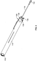
- FIG. 1 shows a schematic representation of a HDD operation.
- a HDD machine 100 is operating a drill string 102 underground along a bore path 104.
- the bore path 104 defines a pilot bore.
- the drill string 102 enters the ground 106 at an entry pit 108 and exits the ground 106 at an exit pit 110. While underground, the drill string 102 follows a generally horizontal path.
- the drill string 102 includes a drilling tool 112 attached to the distal end thereof. Attached to the drilling tool 112 is an underground product 114.
- the HDD machine 100 has completed the drilling of the pilot bore and, as shown by the arrows along the bore path 104, a pullback action is being commenced where the HDD machine is pulling the drill string 102 in a direction back toward the HDD machine 100.
- the drilling tool 112 will be in the entry pit 108, and the underground product 114 will be positioned within the pilot bore.
- the underground product 114 is a conduit sized similarly to the size of the pilot bore. In other embodiments, the underground product 114 is a cable.
- FIGS. 2 and 3 show top and bottom perspective views of the drilling tool 112.
- the drilling tool 112 includes a sonde housing 118 and a drill bit 120 that mounts to the sonde housing 118.
- the drilling tool 112 is configured to be removably attached to the distal end of the drill string 102 such that the drill string 102 can be used to rotate the drilling tool 112 in a rotational cutting motion about a central axis of rotation of the drill string 102.
- the sonde housing 118 is configured for holding a sonde (not shown) used to monitor operational parameters of the drilling tool 112 such as pitch and rotational orientation (i.e., roll position or clock position).
- the sonde can also work with other equipment to allow a geographic position of the drilling tool 112 to be determined.
- the sonde typically interfaces with a control system that is used to control the direction in which the drilling tool 112 travels.
- the sonde can be secured in a compartment of the sonde housing 118 and accessed by removing a cover 122.
- the sonde housing 118 can be configured to allow side loading of the sonde, end loading of the sonde, or other loading configurations.
- the sonde housing 118 is configured to be attached the drill string 102 at a proximal end 119.
- the proximal end 119 of the sonde housing 118 is threaded to receive a threaded portion of the drill string 102 (i.e., a drill rod).
- the sonde housing 118 has a similar cross-sectional area compared to that of the drill string 102.
- the drill bit 120 is mounted to the sonde housing 118 by a plurality of bolts 121, opposite the proximal end 119 of the sonde housing 118.
- the drill bit 120 of the drilling tool 112 comprises a main body 124 and a head portion 126 that includes a plurality of replaceable cutting teeth 128.
- the cutting teeth 128 are mounted to the head portion 126 and are allowed to rotate about the cutting teeth central axes during drilling operations.
- the drill bit 120 further defines an angled face 130 (i.e., a ramp surface) that faces at least partially in the distal direction.
- the angled face 130 is used to facilitate steering of the drilling tool 112.
- a face recess 132 is defined within the angled face 130.
- the drill bit 120 is also configured to receive a portion of the pulling cable 116.
- the drill bit 120 receives the pulling cable 116 at a first pulling cable passage 134 located within the face recess 132.
- the drill bit 120 further includes a second pulling cable passage 136 and a cable recess 138 positioned at a bottom side 142 of the drill bit 120.
- the cable recess 138 joins the first and second pulling cable passages 134, 136.
- the pulling cable 116 is shown to be secured within the drilling tool 112.
- the pulling cable 116 is, in one variant, a steel cable and includes a first end 139 that includes a pulling loop 143 and a second end 141 that is secured within the drilling tool 112.
- a collar 149 (as shown in FIG. 6 ) is attached to the second end 141 to prevent the cable from inadvertently unraveling.
- the pulling cable 116 is also secured within the sonde housing 118 (as shown in FIG. 9 ).
- FIG. 4 shows a top view of the drilling tool 112. Specifically, a reference plane A is shown to bisect the drilling tool 112. The pulling cable 116 is shown positioned along reference plane A. Aligning the pulling cable 116 along the bisector reference plane A helps to promote an even pulling load along the length of the drilling tool 112.
- FIGS. 5-6 show a cross-sectional view of the drilling tool 112 along reference plane A.
- the drill bit 120 is shown attached to the sonde housing 118.
- the pulling cable 116 is secured within the first and second pulling cable passages 134, 136.
- the first pulling cable passage 134 is shown to extend through the drill bit 120 from the face recess 132 of a top side 140 of drill bit 120 to the bottom side 142.
- the first pulling cable passage 134 extends generally along a first passage axis B that extends through the drill bit 120 and is positioned at an angle ⁇ with a longitudinal axis D of the drilling tool 112.
- the first pulling cable passage 134 also includes a curved portion 144 adjacent to the top side 140 that curves as the surface extends in a direction along the first passage axis B.
- the first passage axis B is positioned along reference plane A that generally bisects the main body 124 of the drill bit 120.
- the curved portion 144 is configured to prevent unnecessary friction between the pulling cable 116 and the drill bit 120 and to avoid the provision of a stress riser for the pulling cable 116 at the point of entry into the drill bit 120. Unnecessary friction and/or the provision of a stress riser (e.g., in the form of a corner and/or a sharp angle) could lead to weakening of the cable, possibly leading to a failure.
- a low friction insert and/or coating may be in first pulling cable passage 134 to reduce friction between the pulling cable 116 and the drill bit 120 at the opening of the first pulling cable passage 134 within the face recess 132.
- a beveled portion 145 is used instead of a curved portion 144.
- the beveled portion 145 can be a flat surface that is not perpendicular to the first passage axis B and extends from the first pulling cable passage 134 to the face recess 132 along the portion of the first pulling cable passage 134 closest to the bottom side 142.
- the first pulling cable passage 134 may have a countersunk portion 147.
- the second pulling cable passage 136 extends through the drill bit 120 in a direction from the angled face 130 of top side 140 toward the bottom side 142. As shown, the second pulling cable passage 136 extends generally along a second passage axis C that is perpendicular to the longitudinal axis D of the drilling tool 112. However, in some embodiments, second pulling cable passage 136 is oriented at an angle with the longitudinal axis D.
- first passage axis B and the second passage axis C are parallel with one another. In other embodiments, the first passage axis B and the second passage axis C form an angle ⁇ with one another. In some embodiments, the angle ⁇ is between about 30 degrees and about 60 degrees. In other embodiments, the angle ⁇ is about 45 degrees.
- the cable recess 138 is positioned at the bottom side 142 of the drill bit 120 and extends between and connects the first and second pulling cable passages 134, 136.
- the cable recess 138 has edges that have a rounded profile to prevent unnecessary friction and a limited stress riser between the pulling cable 116 and the drill bit 120. Further, due to the presence of the cable recess 138, when the pulling cable 116 is in position thereat, the pulling cable 116 does not extend out beyond the bottom side 142 or may even be within the confines of the bottom side 142. Such a configuration permits the bottom side 142 of the drill bit 120 to offer a level of protection to the pulling cable 116 during the pullback procedure.
- the pulling cable 116 enters first through the first pulling cable passage 134 at the top side 140 of the drill bit 120.
- the pulling cable 116 is then looped/bent into a looped portion 146 within the cable recess 138 and then passed through the second pulling cable passage 136.
- the second end 141 of the pulling cable 116 remains completely within the second pulling cable passage 136.
- the second end 141 can pass out of the second pulling cable passage 136.
- looped portion 146 of the pulling cable 116 turns an amount in the range of 120 to 240 degrees between the first and second pulling cable passages 134, 136.
- the looped portion 146 allows the pulling cable 116 to be retained within the drilling tool 112 even under an axial load during a pullback action. Additionally, no additional retaining devices are needed to retain the cable within the drill bit 120, thereby lowering the cost of the solution and simplifying installation and removal of the pulling cable 116 and drill bit 120 from one another.
- the drill bit 120 includes only a first pulling cable passage 134.
- a cable retaining device such as an oversized collar, can be used to retain the pulling cable 116 within the first pulling cable passage 134.
- the pulling cable 116 includes a collar 149 that helps to prevent the pulling cable 116 from unraveling.
- the collar 149 can also be sized so that it creates a friction fit within the second pulling cable passage 136, further retaining the pulling cabling 116 within the drilling tool 112.
- FIG. 9 a cross-sectional view of a drilling tool 212, according to one embodiment of the present disclosure, is shown.
- the drilling tool 212 shares many similarities with the drilling tool 112 described above.
- the drilling tool 212 is configured to retain the pulling cable 116 within a drill bit 220 and a sonde housing 218.
- the pulling cable 116 is routed from a top side 240 of the drilling tool 212 through a first passage 234 within the drill bit 220 and then into a second passage 236 within the sonde housing 218.
- the second passage 236 may also pass into a body portion 224 of the drill bit 220.
- the pulling cable 116 rests within a groove 237 between the first and second passages 234, 236 on a bottom side 242 of the drilling tool 212, thereby minimizing the exposure of the pulling cable 116 to wear during the pullback process.
- the pulling cable 116 includes a first bend 113, a second bend 115, and a third bend 117. Each bend 113, 115, 117 helps to retain the pulling cable 116 within the drilling tool 212 even under an axial load.
- the first and second pulling cable passages 234, 236 can include curved and/or beveled surfaces 244, 246, 248 to reduce friction and/or stress risers between the drilling tool 212 and the pulling cable 116 at these locations.
- FIG. 10 shows an alternative embodiment according to the present disclosure. Specifically, an alternative for the loop 143 of the pulling cable 116, as shown in previous embodiments, is depicted.
- the pulling cable 116 is shown attached to the drilling tool 212; however, it can also be attached to the drilling tool 112 of previous embodiments.
- a cylinder 343 is attached to the second end 139 of the pulling cable 116.
- the cylinder 343 is shown to include a groove 344 that is positioned around the surface 345 of the cylinder 343.
- the cylinder 343 is configured to be received by an adapter 346.
- the adapter 346 is configured to interface with an underground product.
- the adapter 346 is also configured to rotate about the cylinder 343 as needed as the underground product is installed in a pullback operation.
- the adapter 346 includes a hole 348 that is sized similar to the cylinder 343 for receiving the cylinder 343.
- the adapter 346 includes a cylinder retaining hole 350.
- the cylinder retaining hole 350 is threaded and configured to align with the groove 344 of the cylinder 343 when the cylinder is inserted into the hole 348.
- the cylinder retaining hole 350 is also configured to receive a set screw 352.
- the set screw 352 is a cup point set screw.
- the set screw 352 is configured to be threaded into the cylinder retaining hole 350 until it is seated within the groove 344 of the cylinder 343. As the adapter 346 rotates about the cylinder 343 during a pullback operation, the set screw 352 travels within the groove 344 of the cylinder 343 so as to retain the cylinder 343 within the adapter 346 under an axial load while allowing rotational movement between the adapter 346 and the drilling tool 212.
- FIG. 11 a perspective view of a drilling tool 412, according to one embodiment of the present disclosure, is shown.
- the drilling tool 412 shares many similarities with the drilling tool 112 described above.
- the drilling tool 412 is configured receive a pullback device 416 in a pullback device passage 434.
- FIGS. 12-13 show side views of the drilling tool 412.
- the drilling tool 412 includes a drill bit 420 mounted to a sonde housing 418 by a plurality of bolts 421 at a distal end 423.
- the drill bit 420 of the drilling tool 412 comprises a main body 424 and a head portion 426 that includes a plurality of replaceable cutting teeth 428.
- FIG. 14 shows a top view of the drilling tool 412. As shown, the pullback device passage 434 is positioned to generally bisect the drill bit 420.
- a cross-sectional view of drilling tool 412 is shown in FIG. 15 .
- the drill bit 420 is configured to receive a portion of the pullback device 416.
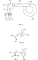
- the pullback device 416 is, in one variant, a rigid, inflexible, device that includes a first end 439 that includes a pulling loop and a second end 441 that is a hook shape. The first end 439 and the second end 441 are connected by a generally linear portion 443.
- the pullback device 416 is manufactured from steel.
- the second end 441 of the pullback device 416 is shown to be positioned within the pullback device passage 434, and then secured within the drilling tool 412. The hook shape of the second end 441 securely maintains the pullback device 416 within the drilling tool when a force F is exerted on the pullback device 416 in a generally axial direction away from the drilling tool 412.
- the hook shape of the second end 441 includes a hook curved portion 445 and an extension 447 extending from the hook curved portion 445.
- the extension 447 defines a hook axis 449.
- the hook axis 449 forms an acute angle ⁇ with the linear portion 443 of the pullback device 416.
- the shape and orientation of the pullback device passage 434 also assists in retaining the pullback device 416 in the drilling tool 412.
- the pullback device passage 434 is shown to extend through the drill bit 420 from a top side 440 of drill bit 420 to the bottom side 442.
- the pullback device passage 434 extends generally along a pullback device passage axis H that extends through the drill bit 420 and is positioned at an angle ⁇ with a longitudinal axis G of the drilling tool 412.
- the hook axis 449 is aligned with the pullback device passage axis H when the pullback device 416 is installed in the pullback device passage 434.
- the angle ⁇ is an acute angle.
- the angle ⁇ can be between about 105 degrees and about 90 degrees. When the angle ⁇ is less than or equal to 90 degrees, forces in a direction away from the drilling tool 412 along the pullback device 412 are minimized so that the pullback device 416 is biased toward retention in the drilling tool 412 during a pullback operation.
- FIG. 17 A cross-sectional schematic view of a bored hole 413 in ground 415 is shown FIG. 17 . Because the pullback device 416 is attached to the drilling tool 412 that is used to bore the hole 413 in the depicted embodiment, the pullback device 416 is also retained within the drilling tool 412 during a pullback operation by the bore hole 413. Because the pullback device 412 must be at least partially lifted, or moved generally perpendicular to the longitudinal axis of the drilling tool 412, the size of bore hole 413 retards such movement due to its diameter being similar to that of the drilling tool 412.
- the bore hole 413 helps to retain the pullback device 416 within the drilling tool 412. Further, a certain level of friction exists between the second end 441 of the pullback device 416 and the pullback device passage 434 that will further promote retention of the pullback device 416 within the pullback device passage 434.
- the pullback device passage 434 also includes a curved portion 444 adjacent to the top side 440 that curves as the surface extends in a direction along the pullback device passage axis H, aiding in minimizing stress risers at this transition region.
- the portion of the pullback device passage 434 nearest the top side 440 is a greater a distance away from a tip 435 of the drill bit than a portion of the pullback device passage 434 nearest the bottom side 442.
- the tip 435 is defined by the most distally positioned tooth 428.
- the curved portion 444 is configured to aid in reducing unnecessary friction and/or the presence of a sharp edge between the pullback device 416 and the drill bit 420.
- the curved portion 444 is configured to interface with the hook curved portion 445 of the second end 441 of the pullback device 416.
- a low friction insert and/or coating may be in pullback device passage 434 at the opening of the pullback device passage 434 to further reduce friction between the pullback device 416 and the drill bit 420.
- a beveled portion is used instead of a curved portion 444.
- the pullback device passage 434 may have countersunk portion.
- the pullback device 416 is sufficiently inflexible and strong enough (e.g., material choice, cross-sectional dimensions, etc.) to be thereby and configured to withstand downhole conditions and deformation during a pullback operation. Further, the pullback device 416 is configured to be reusable for multiple pullback operations. In some embodiments, the pullback device 416 has a Modulus of Elasticity between about 10 x 106 psi and about 32 x 106 psi. In yet a further embodiment, the pullback device 416 may be made of a steel or another material with a similar or higher Modulus of Elasticity.
- FIG. 18 shows a cross-sectional view of a drilling tool 412 configured to receive a pullback device 516 in the pullback device passage 434.
- the pullback device 516 is similar to the pullback device 416 described above.
- the pullback device 516 is a rigid, inflexible, device that includes a first end 539 that includes a pulling loop and a second end 541 that is a hook shape. The first end 539 and the second end 541 are connected by a generally linear portion 543.
- the pullback device 516 is manufactured from steel.
- the second end 541 of the pullback device 516 is shown to be positioned within the pullback device passage 434, and then secured within the drilling tool 412.
- the hook shape of the second end 541 helps maintain the pullback device 516 within the drilling tool 412 when a force F is exerted on the pullback device 516 in a generally axial direction away from the drilling tool 412.
- the pullback device 516 includes a spring ring 519 positioned in a groove 521 at the second end 541 to help retain the pullback device 516 within the drilling tool 412, effectively promoting a friction and/or a force fit within the pullback device passage 434.
- the hook shape of the second end 541 includes a hook curved portion 545 and an extension 547 extending from the hook curved portion 445.
- the extension 547 defines a hook axis 549.
- the hook axis 549 forms an acute angle ⁇ with the linear portion 543 of the pullback device 516.
- FIG. 19 shows a side view of the pullback device 516 with the spring ring 519 installed in groove 521.
- the pullback device 516 is shown uninstalled from the drilling tool 412.
- the second end 541 of the pullback device 516 has a diameter D1
- the spring ring 519 has a diameter D2.
- D2 is greater than D1.
- the spring ring 519 is compressed to a diameter that is less D2 and equal to or greater than D1.
- FIGS. 20-23 show multiple views of the pullback device 516 without the spring ring 519 installed in the groove 521.
- the groove 521 is disposed in the surface of the pullback device 516 at the second end 541.
- the groove 521 has a trough 520 that has a generally rounded profile.
- the trough 520 portion has a diameter less than the diameter D1 of the second end 541.
- FIGS. 24 and 25 show the spring ring 519.
- the spring ring 519 has a generally circular cross-section and is configured to seat in the groove 521.
- the spring ring 519 includes an opening 523 to allow the spring ring 519 to be compressed and clipped in the groove 521.
- the spring ring 519 has an inner diameter ID.
- the inner diameter ID of the spring ring 519 is greater than the diameter of the trough 520 of the groove 521, but less than the diameter D1 of the second end 541 of the pullback device 516. Once seated in the groove 521, the spring ring 519 is positioned loosely around the groove 521.
- the spring ring 519 when the spring ring 519 is installed on the pullback device 516, and the pullback device 516 is installed in the drilling tool 512, the spring ring 519 is compressed.
- the opening 523 of the spring ring 519 allows for such compression. Once compressed, the inner diameter ID is decreased.
- the spring ring 519 has a compressed shape and an uncompressed shape.
- the spring ring 519 is constructed from a material that allows the spring ring 519 to return to the uncompressed shape after being in its compressed shape. By having such elastic behavior, the spring ring 519 exerts a force on the pullback device passage 434 when installed in the drilling tool 412.
- This force along with the fact that the spring ring 519 is retained on the pullback device 516 by the groove 521, helps to retain the pullback device 516 within the pullback device passage 434 of the drilling tool 412.
- Different materials can be used to construct the spring ring 519 to alter the retaining force the spring ring 519 exerts in the pullback device passage 434 when installed in the drilling tool 412.
- the pullback device 516 is sufficiently inflexible and strong enough (e.g., material choice, cross-sectional dimensions, etc.) to be thereby configured to withstand downhole conditions and deformation during a pullback operation. Further, the pullback device 516 is configured to be reusable for multiple pullback operations. In some embodiments, the pullback device 516 has a Modulus of Elasticity between about 10 x 106 psi and about 32 x 106 psi.
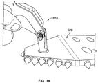
- FIGS. 26-29 show a drilling tool 612 having a drill bit 620 configured to receive a pullback device 616 in a pullback device passage 634.
- the pullback device 616 is configured to connect to the drill bit 620 with a swivel tool 621.
- the pullback device 616 can connect the drill bit 620 with another tool or device.
- the pullback device 616 is configured to be removably positioned within the device passage 634 of the drill bit 620. When positioned within the device passage 634, the pullback device 616 is locked within the passageway 634 so as to maintain the pullback device 616 within the drilling tool 612 when a force F is exerted on the pullback device 616 in a generally axial direction away from the drilling tool 612
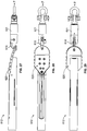
- the pullback device 616 includes a first body 602 and a second body 604 pivotally connected together via a pivot pin 606.
- the pullback device 616 is movable between a closed position, as shown in FIGS. 30 and 31 , and an open position, as shown in FIGS. 32 and 33 .
- the pullback device 616 is constructed of steel.
- the first body 602 includes a retention loop 608 and a leg 610 extending from the retention loop 608.
- the leg 610 defines an upper leg portion 611 and a lower leg portion 613.
- the leg 610 includes a foot element 617 that extends from the lower leg portion 613.
- the lower leg portion 613 is angled away from the upper leg portion 611 in a first direction.
- the foot element 617 is located distal to the retention loop 608, and the foot element 617 extends from the lower leg portion 613 in the first direction.
- the second body 604 is a mirror image of the first body 602.
- the second body 604 includes a retention loop 618 and a leg 619 extending from the retention loop 618.
- the leg 619 defines an upper leg portion 622 and a lower leg portion 623.
- the leg 619 includes a foot element 624 that extends from the lower leg portion 623.
- the lower leg portion 623 is angled away from the upper leg portion 622 in a second direction.
- the foot element 624 is located distal to the retention loop 618, and the foot element 624 extends from the lower leg portion 623 in the second direction.
- the pivot pin 606 links the leg 610 of the first body 602 to the leg 619 of the second body 604.
- the pivot pin is located at a location where the upper leg portion 611 of the first body 602 and the upper leg portion 622 of the second body 604 adjoin the lower leg portion 613 of the first body 602 and the lower leg portion 623 of the second body 604.
- the first body 602 is pivotally connected and thereby linked to the second body 604 in such a manner that the second direction of the foot 624 of the second body 604 is diametrically opposed to the first direction of the foot 617 of the first body 602.
- the first body 602 and the second body 604 are configured to be pivoted about one another.
- the retention loop 608 of the first body 602 and the corresponding retention loop 618 of the second body 604 are generally aligned.
- the upper leg portion 611 of the first body 602 and the corresponding upper leg portion 622 of the second body 604 are also generally aligned with one another, while the lower leg portion 613 of the first body 602 and the lower leg portion 623 of the second body 604 diverge from one another relative to the pivot pin 606.
- the foot 617 of the first body 602 and the foot 624 of the second body 604 each extend laterally beyond a space established by the lower leg portion 613 and the lower leg portion 623.
- the first body 602 and the second body 604 are pivoted so that the lower leg portion 613 of the first body 602 and the foot 617 are generally aligned with, respectively, the lower leg portion 623 of the second body 604 and the second foot 624.
- the retention loop 608 of the first body 602 and the retention loop 618 of the second body 604 are generally misaligned.
- the upper leg 611 of the first body 602 and the upper leg 622 of the second body 604 are generally misaligned with one another.
- the pullback device 616 includes a third body 607, as shown in FIGS. 34-37 . Similar to the first and second bodies 602, 604, the third body 607 includes a retention loop 625 and a leg 626 extending from the retention loop 625. In some embodiments, the third body 607 is identical the first and second bodies 602, 604 and pivotally connected by the pivot pin 606 to the first and second bodies 602, 604. Further, as shown in FIGS. 33 and 34 , when in the device 616 is in the closed position, the retention loops of the first, second, and third bodies are aligned. Further, as shown in FIGS. 35 and 36 , when the device 616 is in the open position, the retention loops of the first, second, and third bodies are misaligned.
- the first body 602 and the second body 604 are first positioned in the open position to be inserted into the passageway 634 and then pivoted into the closed position to retain the pullback device 616 in passageway 634 within the drill bit 620.
- a cross pin (not shown) can be used to lock the pullback device 616 in the closed position when the pullback device 616 is installed on the drilling tool 612.
- the pullback device 616 can be use in other applications, other than drilling. In some embodiments, the pullback device 616 can be used as a lifting device for towing vehicles, or other similar applications where a pulling device can be utilized.
- the drilling tool 112 can be connected to other types of drive members such as rods, stems, subs, or other structures that do not contain sondes.
- carbide buttons are provided at various locations on the drill bits 120, 220 to limit wear and enhance drilling productivity.
Landscapes
- Engineering & Computer Science (AREA)
- Life Sciences & Earth Sciences (AREA)
- Geology (AREA)
- Mining & Mineral Resources (AREA)
- Physics & Mathematics (AREA)
- Environmental & Geological Engineering (AREA)
- Fluid Mechanics (AREA)
- General Life Sciences & Earth Sciences (AREA)
- Geochemistry & Mineralogy (AREA)
- Mechanical Engineering (AREA)
- Geophysics (AREA)
- Processing Of Stones Or Stones Resemblance Materials (AREA)
Claims (12)
- Outil de forage (112 ; 212 ; 412 ; 512 ; 612) comprenant :
un corps de mèche de forage (124 ; 224 ; 424) portant une pluralité de dents de coupe (128), le corps de mèche de forage (124 ; 224 ; 424) ayant un premier côté et un second côté opposé, le corps de mèche de forage (124 ; 224 ; 424) définissant un premier passage de dispositif de rappel (134 ; 234 ; 434) qui s'étend à travers le corps de mèche de forage (124 ; 224 ; 424) du premier côté au second côté, le premier passage de dispositif de rappel (134 ; 234 ; 434) étant configuré pour recevoir une partie d'un dispositif de rappel (116 ; 416 ; 516 ; 616) à l'intérieur de celui-ci, le premier passage de dispositif de rappel (134 ; 234 ; 434) s'étendant généralement le long d'un axe de passage (B ; H) qui s'étend à travers le corps de mèche de forage (124 ; 224 ; 424), le premier passage de dispositif de rappel (134 ; 234 ; 434) comprenant au moins une partie adjacente au premier côté qui est au moins une surface parmi une surface qui est incurvée et biseautée au fur et à mesure que la surface s'étend suivant une direction le long de l'axe de passage, l'axe de passage étant positionné le long d'un plan de référence qui croise généralement longitudinalement le corps de mèche de forage (124 ; 224 ; 424), l'outil de forage étant caractérisé en ce que ledit axe de passage (B ; H) forme un angle avec l'axe longitudinal du corps de mèche de forage (124 ; 224 ; 424). - Outil de forage (112 ; 212 ; 412 ; 512 ; 612) selon la revendication 1, comprenant en outre un dispositif de rappel (116 ; 416 ; 516 ; 616) pouvant être positionné à l'intérieur du premier passage de dispositif de rappel (134 ; 234 ; 434).
- Outil de forage (112 ; 212 ; 412 ; 512 ; 612) selon la revendication 1, comprenant en outre un dispositif de rappel rigide (116 ; 416 ; 516 ; 616) ayant une boucle de rappel à une première extrémité et un crochet d'outil de forage à une seconde extrémité, dans lequel le crochet d'outil de forage peut être positionné à l'intérieur du premier passage de dispositif de rappel (134 ; 234 ; 434).
- Outil de forage (112 ; 212 ; 412 ; 512 ; 612) selon la revendication 3, dans lequel le crochet d'outil de forage du dispositif de rappel (116 ; 416 ; 516 ; 616) comprend une partie incurvée qui est configurée pour entrer en interface avec la partie du premier passage de dispositif de rappel (134 ; 234 ; 434) qui est au moins une surface parmi une surface incurvée et biseautée.
- Outil de forage (112 ; 212 ; 412 ; 512 ; 612) selon la revendication 3, dans lequel le dispositif de rappel rigide (116 ; 416 ; 516 ; 616) comprend en outre une bague d'arrêt à ressort (519) disposée dans un renfoncement à la seconde extrémité, dans lequel la bague d'arrêt à ressort (519) est configurée pour exercer une force de retenue à l'intérieur du premier passage de dispositif de rappel (134 ; 234 ; 434).
- Outil de forage (112 ; 212 ; 412 ; 512 ; 612) selon la revendication 3, dans lequel le crochet d'outil de forage du dispositif de rappel (116 ; 416 ; 516 ; 616) est positionné à l'intérieur du premier passage de dispositif de rappel (134 ; 234 ; 434) quand une force qui est généralement alignée de manière longitudinale au corps de mèche de forage (124 ; 224 ; 424) est exercée sur la boucle de rappel du dispositif de rappel (116 ; 416 ; 516 ; 616) suivant une direction en éloignement du corps de mèche de forage (124 ; 224 ; 424).
- Outil de forage (112 ; 212 ; 412 ; 512 ; 612) selon la revendication 1, dans lequel l'outil de forage (112 ; 212 ; 412 ; 512 ; 612) comprend en outre un boîtier de sonde (118 ; 218 ; 418) auquel se fixe le corps de mèche de forage (124 ; 224 ; 424), et dans lequel le boîtier de sonde (118 ; 218 ; 418) définit un second passage de dispositif de rappel (134 ; 234 ; 434) qui est configuré pour recevoir une partie du dispositif de rappel (116 ; 416 ; 516 ; 616) à l'intérieur de celui-ci.
- Outil de forage (112 ; 212 ; 412 ; 512 ; 612) selon la revendication 1, dans lequel le corps de mèche de forage (124 ; 224 ; 424) définit également un second passage de dispositif de rappel (136) qui est configuré pour recevoir une partie du dispositif de rappel (116 ; 416 ; 516 ; 616) à l'intérieur de celui-ci.
- Outil de forage (112 ; 212 ; 412 ; 512 ; 612) selon la revendication 1, dans lequel le corps de mèche de forage (124 ; 224 ; 424) a un embout avant (435) destiné à s'engager dans une surface de sol, et dans lequel la partie du premier passage de dispositif de rappel (134 ; 234 ; 434) adjacente au premier côté du corps de mèche de forage (124 ; 224 ; 424) est située à une plus grande distance en éloignement de l'embout avant (435) du corps de mèche de forage (124 ; 224 ; 424) qu'une partie du premier passage de dispositif de rappel (134 ; 234 ; 434) adjacente au second côté du corps de mèche de forage (124 ; 224 ; 424).
- Outil de forage (112 ; 212 ; 412 ; 512 ; 612) selon la revendication 1, dans lequel le corps de mèche de forage (124 ; 224 ; 424) a un embout avant (435) destiné à s'engager dans une surface de sol, et dans lequel la partie du premier passage de dispositif de rappel (134 ; 234 ; 434) adjacente au second côté du corps de mèche de forage (124 ; 224 ; 424) est située à une plus grande distance en éloignement de l'embout avant (435) du corps de mèche de forage (124 ; 224 ; 424) qu'une partie du premier passage de dispositif de rappel (134 ; 234 ; 434) adjacente au premier côté du corps de mèche de forage (124 ; 224 ; 424).
- Outil de forage (112 ; 212 ; 412 ; 512 ; 612) selon la revendication 1, dans lequel l'angle est un angle aigu.
- Outil de forage (112 ; 212 ; 412 ; 512 ; 612) selon la revendication 1, dans lequel l'angle est entre environ 105 degrés et environ 90 degrés.
Applications Claiming Priority (3)
| Application Number | Priority Date | Filing Date | Title |
|---|---|---|---|
| US201562203151P | 2015-08-10 | 2015-08-10 | |
| US201662294802P | 2016-02-12 | 2016-02-12 | |
| US201662326606P | 2016-04-22 | 2016-04-22 |
Publications (2)
| Publication Number | Publication Date |
|---|---|
| EP3130744A1 EP3130744A1 (fr) | 2017-02-15 |
| EP3130744B1 true EP3130744B1 (fr) | 2018-09-26 |
Family
ID=56571253
Family Applications (1)
| Application Number | Title | Priority Date | Filing Date |
|---|---|---|---|
| EP16182804.1A Active EP3130744B1 (fr) | 2015-08-10 | 2016-08-04 | Système de rappel pour outil de forage |
Country Status (4)
| Country | Link |
|---|---|
| US (1) | US10208541B2 (fr) |
| EP (1) | EP3130744B1 (fr) |
| AU (1) | AU2016210651A1 (fr) |
| CA (1) | CA2938091A1 (fr) |
Families Citing this family (5)
| Publication number | Priority date | Publication date | Assignee | Title |
|---|---|---|---|---|
| US10900294B2 (en) | 2018-08-22 | 2021-01-26 | Vermeer Manufacturing Company | Pullback system for drilling tool |
| US11105156B2 (en) * | 2019-02-05 | 2021-08-31 | Vermeer Manufacturing Company | Pullback system for drilling tool |
| CN120312114A (zh) * | 2019-08-21 | 2025-07-15 | 维米尔制造公司 | 用于钻井工具的回拉系统 |
| US11913287B2 (en) | 2021-09-16 | 2024-02-27 | Vermeer Manufacturing Company | Mounting arrangement for pullback adaptor |
| WO2024112326A1 (fr) * | 2022-11-22 | 2024-05-30 | Chris Payne | Systèmes, dispositifs et/ou procédés d'extraction de foreuse |
Family Cites Families (30)
| Publication number | Priority date | Publication date | Assignee | Title |
|---|---|---|---|---|
| US2225128A (en) * | 1939-01-09 | 1940-12-17 | William D Osborn | Rod coupling |
| US4270618A (en) | 1979-04-20 | 1981-06-02 | The Robbins Company | Earth boring apparatus |
| DE3176344D1 (en) | 1980-12-02 | 1987-09-10 | British Gas Corp | Improvements in the replacement of mains |
| US4507019A (en) | 1983-02-22 | 1985-03-26 | Expand-A-Line, Incorporated | Method and apparatus for replacing buried pipe |
| US4679637A (en) | 1985-05-14 | 1987-07-14 | Cherrington Martin D | Apparatus and method for forming an enlarged underground arcuate bore and installing a conduit therein |
| US4784230A (en) | 1985-05-14 | 1988-11-15 | Cherrington Martin D | Apparatus and method for installing a conduit within an arcuate bore |
| US4785885A (en) | 1987-05-13 | 1988-11-22 | Cherrington Martin D | Method and apparatus for cementing a production conduit within an underground arcuate bore |
| US4911579A (en) | 1988-01-22 | 1990-03-27 | Flowmole Corporation | Swivel arrangement for connecting a boring or reaming tool to a cable |
| US5033907A (en) | 1990-02-16 | 1991-07-23 | Donnell Hugh W O | Pipe alignment device |
| US5192165A (en) | 1992-04-06 | 1993-03-09 | Pim Corporation | Trenchless replacement of conduits in an underground conduit bank |
| US5651647A (en) | 1995-10-11 | 1997-07-29 | Gbr Pilot Master, Inc. | Auxiliary chuck and screwdriver for electric drills |
| WO1998030350A1 (fr) | 1997-01-09 | 1998-07-16 | Robert Ward Carter | Dispositif pour le remplacement de tuyauterie souterraine sans creuser de tranchee |
| DE19713640C1 (de) | 1997-04-02 | 1998-10-29 | Terra Ag Tiefbautechnik | Vorrichtung zum Einziehen eines Rohrs in eine Erdbohrung |
| US6109832A (en) | 1998-04-02 | 2000-08-29 | Lincoln; David A. | Ram burster and method for installing tubular casing underground |
| US6148935A (en) | 1998-08-24 | 2000-11-21 | Earth Tool Company, L.L.C. | Joint for use in a directional boring apparatus |
| US20020112890A1 (en) * | 2001-01-22 | 2002-08-22 | Wentworth Steven W. | Conduit pulling apparatus and method for use in horizontal drilling |
| US20030106714A1 (en) | 2001-12-12 | 2003-06-12 | Smith Michael Lee | Use of coiled tubing unit systems in sub sea operations |
| US7318491B2 (en) | 2005-04-28 | 2008-01-15 | Astec Industries, Inc. | Apparatus and method for modified horizontal directional drilling assembly |
| US8033345B1 (en) | 2004-04-30 | 2011-10-11 | Astec Industries, Inc. | Apparatus and method for a drilling assembly |
| US7243737B2 (en) | 2004-09-22 | 2007-07-17 | Vermeer Manufacturing Company | Interchangeable reamer |
| US7976243B2 (en) | 2006-06-15 | 2011-07-12 | Green Core Technologies, Llc | Methods and apparatus for installing conduit underground |
| WO2007143773A1 (fr) | 2006-06-16 | 2007-12-21 | Harrofam Pty Ltd | Système et appareil de microtunnelage |
| US8365841B2 (en) | 2008-04-03 | 2013-02-05 | Dimitroff Ted R | Sectional back reamer apparatus and method for horizontal directional drilling |
| US8122979B1 (en) * | 2008-12-19 | 2012-02-28 | Radius Hdd Direct, Llc | Offset rock bit with pull back adapter |
| US8529156B2 (en) | 2009-08-06 | 2013-09-10 | True.Home Heating/Cooling, Inc. | Bit adapter and tube return for vertizontal geothermal loop |
| US8256531B1 (en) | 2009-08-06 | 2012-09-04 | Williams Comfort Air, Inc. | Vertizontal geothermal loop and installation method |
| US8887833B2 (en) * | 2010-08-20 | 2014-11-18 | Earth Tool Company, Llc | Reamer assembly |
| US9169946B2 (en) * | 2013-03-08 | 2015-10-27 | Earth Tool Company Llc | Directional drill hammer pullback device |
| US20140367175A1 (en) * | 2013-03-14 | 2014-12-18 | Cary Cooper | Drill bit assembly for a directional percussion boring system |
| US9719344B2 (en) | 2014-02-14 | 2017-08-01 | Melfred Borzall, Inc. | Direct pullback devices and method of horizontal drilling |
-
2016
- 2016-08-03 AU AU2016210651A patent/AU2016210651A1/en not_active Abandoned
- 2016-08-04 CA CA2938091A patent/CA2938091A1/fr not_active Abandoned
- 2016-08-04 EP EP16182804.1A patent/EP3130744B1/fr active Active
- 2016-08-09 US US15/232,345 patent/US10208541B2/en active Active
Non-Patent Citations (1)
| Title |
|---|
| None * |
Also Published As
| Publication number | Publication date |
|---|---|
| US10208541B2 (en) | 2019-02-19 |
| AU2016210651A1 (en) | 2017-03-02 |
| CA2938091A1 (fr) | 2017-02-10 |
| US20170044835A1 (en) | 2017-02-16 |
| EP3130744A1 (fr) | 2017-02-15 |
Similar Documents
| Publication | Publication Date | Title |
|---|---|---|
| EP3130744B1 (fr) | Système de rappel pour outil de forage | |
| US20020112890A1 (en) | Conduit pulling apparatus and method for use in horizontal drilling | |
| EP2677112B1 (fr) | Ensemble de forage de fonds de puits | |
| US7954566B2 (en) | Stabilizer for drill strings | |
| US9243453B2 (en) | Method for operating a horizontal drilling device and horizontal drilling device | |
| JPS5833358B2 (ja) | キツクオ−バ−ソウチ | |
| AU2013361158B2 (en) | Overshot assembly and systems and methods of using same | |
| US9534445B2 (en) | Rotary steerable tool | |
| US20100212969A1 (en) | Stabilizer assemblies with bearing pad locking structures and tools incorporating same | |
| US10975625B2 (en) | Simple rotary steerable drilling system | |
| CN107207224B (zh) | 伸缩臂的耐磨垫的改进 | |
| US12286843B2 (en) | Dual pipe drill head quick interchange joint | |
| WO2013028075A1 (fr) | Ensemble douille excentrée ajustable pour carottier directionnel à câble | |
| US20100212970A1 (en) | Stabilizer assemblies with bearing pad locking structures and tools incorporating same | |
| CN110036176B (zh) | 用于安装钻头的方法、装置和保持器 | |
| US6021856A (en) | Bit retention system | |
| US20130105225A1 (en) | Horizontal drilling device | |
| US20210047888A1 (en) | Pivot coupling | |
| EP2574415A1 (fr) | Adaptateur pour le passage de câbles ou tuyaux | |
| US20220268118A1 (en) | Ergonomic core drilling system shoe interface | |
| WO2023025341A1 (fr) | Excavateur de puits | |
| US20180126535A1 (en) | Magnetic retention device for a hydraulic hammer bushing | |
| US20240229562A1 (en) | Cutter assembly |
Legal Events
| Date | Code | Title | Description |
|---|---|---|---|
| PUAI | Public reference made under article 153(3) epc to a published international application that has entered the european phase |
Free format text: ORIGINAL CODE: 0009012 |
|
| STAA | Information on the status of an ep patent application or granted ep patent |
Free format text: STATUS: THE APPLICATION HAS BEEN PUBLISHED |
|
| AK | Designated contracting states |
Kind code of ref document: A1 Designated state(s): AL AT BE BG CH CY CZ DE DK EE ES FI FR GB GR HR HU IE IS IT LI LT LU LV MC MK MT NL NO PL PT RO RS SE SI SK SM TR |
|
| AX | Request for extension of the european patent |
Extension state: BA ME |
|
| STAA | Information on the status of an ep patent application or granted ep patent |
Free format text: STATUS: REQUEST FOR EXAMINATION WAS MADE |
|
| 17P | Request for examination filed |
Effective date: 20170810 |
|
| RBV | Designated contracting states (corrected) |
Designated state(s): AL AT BE BG CH CY CZ DE DK EE ES FI FR GB GR HR HU IE IS IT LI LT LU LV MC MK MT NL NO PL PT RO RS SE SI SK SM TR |
|
| GRAP | Despatch of communication of intention to grant a patent |
Free format text: ORIGINAL CODE: EPIDOSNIGR1 |
|
| STAA | Information on the status of an ep patent application or granted ep patent |
Free format text: STATUS: GRANT OF PATENT IS INTENDED |
|
| INTG | Intention to grant announced |
Effective date: 20180307 |
|
| GRAS | Grant fee paid |
Free format text: ORIGINAL CODE: EPIDOSNIGR3 |
|
| GRAA | (expected) grant |
Free format text: ORIGINAL CODE: 0009210 |
|
| STAA | Information on the status of an ep patent application or granted ep patent |
Free format text: STATUS: THE PATENT HAS BEEN GRANTED |
|
| AK | Designated contracting states |
Kind code of ref document: B1 Designated state(s): AL AT BE BG CH CY CZ DE DK EE ES FI FR GB GR HR HU IE IS IT LI LT LU LV MC MK MT NL NO PL PT RO RS SE SI SK SM TR |
|
| REG | Reference to a national code |
Ref country code: GB Ref legal event code: FG4D |
|
| REG | Reference to a national code |
Ref country code: CH Ref legal event code: EP |
|
| REG | Reference to a national code |
Ref country code: AT Ref legal event code: REF Ref document number: 1046237 Country of ref document: AT Kind code of ref document: T Effective date: 20181015 |
|
| REG | Reference to a national code |
Ref country code: IE Ref legal event code: FG4D |
|
| REG | Reference to a national code |
Ref country code: DE Ref legal event code: R096 Ref document number: 602016005950 Country of ref document: DE |
|
| REG | Reference to a national code |
Ref country code: NL Ref legal event code: MP Effective date: 20180926 |
|
| PG25 | Lapsed in a contracting state [announced via postgrant information from national office to epo] |
Ref country code: NO Free format text: LAPSE BECAUSE OF FAILURE TO SUBMIT A TRANSLATION OF THE DESCRIPTION OR TO PAY THE FEE WITHIN THE PRESCRIBED TIME-LIMIT Effective date: 20181226 Ref country code: GR Free format text: LAPSE BECAUSE OF FAILURE TO SUBMIT A TRANSLATION OF THE DESCRIPTION OR TO PAY THE FEE WITHIN THE PRESCRIBED TIME-LIMIT Effective date: 20181227 Ref country code: FI Free format text: LAPSE BECAUSE OF FAILURE TO SUBMIT A TRANSLATION OF THE DESCRIPTION OR TO PAY THE FEE WITHIN THE PRESCRIBED TIME-LIMIT Effective date: 20180926 Ref country code: RS Free format text: LAPSE BECAUSE OF FAILURE TO SUBMIT A TRANSLATION OF THE DESCRIPTION OR TO PAY THE FEE WITHIN THE PRESCRIBED TIME-LIMIT Effective date: 20180926 Ref country code: LT Free format text: LAPSE BECAUSE OF FAILURE TO SUBMIT A TRANSLATION OF THE DESCRIPTION OR TO PAY THE FEE WITHIN THE PRESCRIBED TIME-LIMIT Effective date: 20180926 Ref country code: BG Free format text: LAPSE BECAUSE OF FAILURE TO SUBMIT A TRANSLATION OF THE DESCRIPTION OR TO PAY THE FEE WITHIN THE PRESCRIBED TIME-LIMIT Effective date: 20181226 |
|
| REG | Reference to a national code |
Ref country code: LT Ref legal event code: MG4D |
|
| PG25 | Lapsed in a contracting state [announced via postgrant information from national office to epo] |
Ref country code: AL Free format text: LAPSE BECAUSE OF FAILURE TO SUBMIT A TRANSLATION OF THE DESCRIPTION OR TO PAY THE FEE WITHIN THE PRESCRIBED TIME-LIMIT Effective date: 20180926 Ref country code: LV Free format text: LAPSE BECAUSE OF FAILURE TO SUBMIT A TRANSLATION OF THE DESCRIPTION OR TO PAY THE FEE WITHIN THE PRESCRIBED TIME-LIMIT Effective date: 20180926 Ref country code: HR Free format text: LAPSE BECAUSE OF FAILURE TO SUBMIT A TRANSLATION OF THE DESCRIPTION OR TO PAY THE FEE WITHIN THE PRESCRIBED TIME-LIMIT Effective date: 20180926 |
|
| REG | Reference to a national code |
Ref country code: AT Ref legal event code: MK05 Ref document number: 1046237 Country of ref document: AT Kind code of ref document: T Effective date: 20180926 |
|
| PG25 | Lapsed in a contracting state [announced via postgrant information from national office to epo] |
Ref country code: NL Free format text: LAPSE BECAUSE OF FAILURE TO SUBMIT A TRANSLATION OF THE DESCRIPTION OR TO PAY THE FEE WITHIN THE PRESCRIBED TIME-LIMIT Effective date: 20180926 Ref country code: EE Free format text: LAPSE BECAUSE OF FAILURE TO SUBMIT A TRANSLATION OF THE DESCRIPTION OR TO PAY THE FEE WITHIN THE PRESCRIBED TIME-LIMIT Effective date: 20180926 Ref country code: PL Free format text: LAPSE BECAUSE OF FAILURE TO SUBMIT A TRANSLATION OF THE DESCRIPTION OR TO PAY THE FEE WITHIN THE PRESCRIBED TIME-LIMIT Effective date: 20180926 Ref country code: IS Free format text: LAPSE BECAUSE OF FAILURE TO SUBMIT A TRANSLATION OF THE DESCRIPTION OR TO PAY THE FEE WITHIN THE PRESCRIBED TIME-LIMIT Effective date: 20190126 Ref country code: AT Free format text: LAPSE BECAUSE OF FAILURE TO SUBMIT A TRANSLATION OF THE DESCRIPTION OR TO PAY THE FEE WITHIN THE PRESCRIBED TIME-LIMIT Effective date: 20180926 Ref country code: ES Free format text: LAPSE BECAUSE OF FAILURE TO SUBMIT A TRANSLATION OF THE DESCRIPTION OR TO PAY THE FEE WITHIN THE PRESCRIBED TIME-LIMIT Effective date: 20180926 Ref country code: RO Free format text: LAPSE BECAUSE OF FAILURE TO SUBMIT A TRANSLATION OF THE DESCRIPTION OR TO PAY THE FEE WITHIN THE PRESCRIBED TIME-LIMIT Effective date: 20180926 Ref country code: CZ Free format text: LAPSE BECAUSE OF FAILURE TO SUBMIT A TRANSLATION OF THE DESCRIPTION OR TO PAY THE FEE WITHIN THE PRESCRIBED TIME-LIMIT Effective date: 20180926 Ref country code: IT Free format text: LAPSE BECAUSE OF FAILURE TO SUBMIT A TRANSLATION OF THE DESCRIPTION OR TO PAY THE FEE WITHIN THE PRESCRIBED TIME-LIMIT Effective date: 20180926 |
|
| PG25 | Lapsed in a contracting state [announced via postgrant information from national office to epo] |
Ref country code: SM Free format text: LAPSE BECAUSE OF FAILURE TO SUBMIT A TRANSLATION OF THE DESCRIPTION OR TO PAY THE FEE WITHIN THE PRESCRIBED TIME-LIMIT Effective date: 20180926 Ref country code: PT Free format text: LAPSE BECAUSE OF FAILURE TO SUBMIT A TRANSLATION OF THE DESCRIPTION OR TO PAY THE FEE WITHIN THE PRESCRIBED TIME-LIMIT Effective date: 20190126 Ref country code: SK Free format text: LAPSE BECAUSE OF FAILURE TO SUBMIT A TRANSLATION OF THE DESCRIPTION OR TO PAY THE FEE WITHIN THE PRESCRIBED TIME-LIMIT Effective date: 20180926 |
|
| REG | Reference to a national code |
Ref country code: DE Ref legal event code: R097 Ref document number: 602016005950 Country of ref document: DE |
|
| PG25 | Lapsed in a contracting state [announced via postgrant information from national office to epo] |
Ref country code: DK Free format text: LAPSE BECAUSE OF FAILURE TO SUBMIT A TRANSLATION OF THE DESCRIPTION OR TO PAY THE FEE WITHIN THE PRESCRIBED TIME-LIMIT Effective date: 20180926 |
|
| PLBE | No opposition filed within time limit |
Free format text: ORIGINAL CODE: 0009261 |
|
| STAA | Information on the status of an ep patent application or granted ep patent |
Free format text: STATUS: NO OPPOSITION FILED WITHIN TIME LIMIT |
|
| 26N | No opposition filed |
Effective date: 20190627 |
|
| PG25 | Lapsed in a contracting state [announced via postgrant information from national office to epo] |
Ref country code: SI Free format text: LAPSE BECAUSE OF FAILURE TO SUBMIT A TRANSLATION OF THE DESCRIPTION OR TO PAY THE FEE WITHIN THE PRESCRIBED TIME-LIMIT Effective date: 20180926 |
|
| PG25 | Lapsed in a contracting state [announced via postgrant information from national office to epo] |
Ref country code: TR Free format text: LAPSE BECAUSE OF FAILURE TO SUBMIT A TRANSLATION OF THE DESCRIPTION OR TO PAY THE FEE WITHIN THE PRESCRIBED TIME-LIMIT Effective date: 20180926 |
|
| PG25 | Lapsed in a contracting state [announced via postgrant information from national office to epo] |
Ref country code: MC Free format text: LAPSE BECAUSE OF FAILURE TO SUBMIT A TRANSLATION OF THE DESCRIPTION OR TO PAY THE FEE WITHIN THE PRESCRIBED TIME-LIMIT Effective date: 20180926 Ref country code: LU Free format text: LAPSE BECAUSE OF NON-PAYMENT OF DUE FEES Effective date: 20190804 Ref country code: CH Free format text: LAPSE BECAUSE OF NON-PAYMENT OF DUE FEES Effective date: 20190831 Ref country code: LI Free format text: LAPSE BECAUSE OF NON-PAYMENT OF DUE FEES Effective date: 20190831 |
|
| REG | Reference to a national code |
Ref country code: BE Ref legal event code: MM Effective date: 20190831 |
|
| PG25 | Lapsed in a contracting state [announced via postgrant information from national office to epo] |
Ref country code: FR Free format text: LAPSE BECAUSE OF NON-PAYMENT OF DUE FEES Effective date: 20190831 Ref country code: IE Free format text: LAPSE BECAUSE OF NON-PAYMENT OF DUE FEES Effective date: 20190804 |
|
| PG25 | Lapsed in a contracting state [announced via postgrant information from national office to epo] |
Ref country code: BE Free format text: LAPSE BECAUSE OF NON-PAYMENT OF DUE FEES Effective date: 20190831 |
|
| GBPC | Gb: european patent ceased through non-payment of renewal fee |
Effective date: 20200804 |
|
| PG25 | Lapsed in a contracting state [announced via postgrant information from national office to epo] |
Ref country code: CY Free format text: LAPSE BECAUSE OF FAILURE TO SUBMIT A TRANSLATION OF THE DESCRIPTION OR TO PAY THE FEE WITHIN THE PRESCRIBED TIME-LIMIT Effective date: 20180926 |
|
| PG25 | Lapsed in a contracting state [announced via postgrant information from national office to epo] |
Ref country code: SE Free format text: LAPSE BECAUSE OF NON-PAYMENT OF DUE FEES Effective date: 20180926 |
|
| PG25 | Lapsed in a contracting state [announced via postgrant information from national office to epo] |
Ref country code: HU Free format text: LAPSE BECAUSE OF FAILURE TO SUBMIT A TRANSLATION OF THE DESCRIPTION OR TO PAY THE FEE WITHIN THE PRESCRIBED TIME-LIMIT; INVALID AB INITIO Effective date: 20160804 Ref country code: MT Free format text: LAPSE BECAUSE OF FAILURE TO SUBMIT A TRANSLATION OF THE DESCRIPTION OR TO PAY THE FEE WITHIN THE PRESCRIBED TIME-LIMIT Effective date: 20180926 |
|
| PG25 | Lapsed in a contracting state [announced via postgrant information from national office to epo] |
Ref country code: GB Free format text: LAPSE BECAUSE OF NON-PAYMENT OF DUE FEES Effective date: 20200804 |
|
| PG25 | Lapsed in a contracting state [announced via postgrant information from national office to epo] |
Ref country code: MK Free format text: LAPSE BECAUSE OF FAILURE TO SUBMIT A TRANSLATION OF THE DESCRIPTION OR TO PAY THE FEE WITHIN THE PRESCRIBED TIME-LIMIT Effective date: 20180926 |
|
| P01 | Opt-out of the competence of the unified patent court (upc) registered |
Effective date: 20230525 |
|
| PGFP | Annual fee paid to national office [announced via postgrant information from national office to epo] |
Ref country code: DE Payment date: 20250709 Year of fee payment: 10 |