EP3130759A1 - Joint à membrane de turbine à gaz - Google Patents
Joint à membrane de turbine à gaz Download PDFInfo
- Publication number
- EP3130759A1 EP3130759A1 EP15181039.7A EP15181039A EP3130759A1 EP 3130759 A1 EP3130759 A1 EP 3130759A1 EP 15181039 A EP15181039 A EP 15181039A EP 3130759 A1 EP3130759 A1 EP 3130759A1
- Authority
- EP
- European Patent Office
- Prior art keywords
- membrane
- gas turbine
- fretting
- face
- seal
- Prior art date
- Legal status (The legal status is an assumption and is not a legal conclusion. Google has not performed a legal analysis and makes no representation as to the accuracy of the status listed.)
- Granted
Links
Images



Classifications
-
- F—MECHANICAL ENGINEERING; LIGHTING; HEATING; WEAPONS; BLASTING
- F01—MACHINES OR ENGINES IN GENERAL; ENGINE PLANTS IN GENERAL; STEAM ENGINES
- F01D—NON-POSITIVE DISPLACEMENT MACHINES OR ENGINES, e.g. STEAM TURBINES
- F01D11/00—Preventing or minimising internal leakage of working-fluid, e.g. between stages
- F01D11/003—Preventing or minimising internal leakage of working-fluid, e.g. between stages by packing rings; Mechanical seals
-
- F—MECHANICAL ENGINEERING; LIGHTING; HEATING; WEAPONS; BLASTING
- F01—MACHINES OR ENGINES IN GENERAL; ENGINE PLANTS IN GENERAL; STEAM ENGINES
- F01D—NON-POSITIVE DISPLACEMENT MACHINES OR ENGINES, e.g. STEAM TURBINES
- F01D11/00—Preventing or minimising internal leakage of working-fluid, e.g. between stages
- F01D11/005—Sealing means between non relatively rotating elements
-
- F—MECHANICAL ENGINEERING; LIGHTING; HEATING; WEAPONS; BLASTING
- F01—MACHINES OR ENGINES IN GENERAL; ENGINE PLANTS IN GENERAL; STEAM ENGINES
- F01D—NON-POSITIVE DISPLACEMENT MACHINES OR ENGINES, e.g. STEAM TURBINES
- F01D25/00—Component parts, details, or accessories, not provided for in, or of interest apart from, other groups
- F01D25/24—Casings; Casing parts, e.g. diaphragms, casing fastenings
- F01D25/246—Fastening of diaphragms or stator-rings
-
- F—MECHANICAL ENGINEERING; LIGHTING; HEATING; WEAPONS; BLASTING
- F16—ENGINEERING ELEMENTS AND UNITS; GENERAL MEASURES FOR PRODUCING AND MAINTAINING EFFECTIVE FUNCTIONING OF MACHINES OR INSTALLATIONS; THERMAL INSULATION IN GENERAL
- F16J—PISTONS; CYLINDERS; SEALINGS
- F16J3/00—Diaphragms; Bellows; Bellows pistons
- F16J3/02—Diaphragms
-
- F—MECHANICAL ENGINEERING; LIGHTING; HEATING; WEAPONS; BLASTING
- F23—COMBUSTION APPARATUS; COMBUSTION PROCESSES
- F23R—GENERATING COMBUSTION PRODUCTS OF HIGH PRESSURE OR HIGH VELOCITY, e.g. GAS-TURBINE COMBUSTION CHAMBERS
- F23R3/00—Continuous combustion chambers using liquid or gaseous fuel
- F23R3/42—Continuous combustion chambers using liquid or gaseous fuel characterised by the arrangement or form of the flame tubes or combustion chambers
- F23R3/60—Support structures; Attaching or mounting means
-
- F—MECHANICAL ENGINEERING; LIGHTING; HEATING; WEAPONS; BLASTING
- F05—INDEXING SCHEMES RELATING TO ENGINES OR PUMPS IN VARIOUS SUBCLASSES OF CLASSES F01-F04
- F05D—INDEXING SCHEME FOR ASPECTS RELATING TO NON-POSITIVE-DISPLACEMENT MACHINES OR ENGINES, GAS-TURBINES OR JET-PROPULSION PLANTS
- F05D2220/00—Application
- F05D2220/30—Application in turbines
- F05D2220/32—Application in turbines in gas turbines
-
- F—MECHANICAL ENGINEERING; LIGHTING; HEATING; WEAPONS; BLASTING
- F05—INDEXING SCHEMES RELATING TO ENGINES OR PUMPS IN VARIOUS SUBCLASSES OF CLASSES F01-F04
- F05D—INDEXING SCHEME FOR ASPECTS RELATING TO NON-POSITIVE-DISPLACEMENT MACHINES OR ENGINES, GAS-TURBINES OR JET-PROPULSION PLANTS
- F05D2230/00—Manufacture
- F05D2230/80—Repairing, retrofitting or upgrading methods
-
- F—MECHANICAL ENGINEERING; LIGHTING; HEATING; WEAPONS; BLASTING
- F05—INDEXING SCHEMES RELATING TO ENGINES OR PUMPS IN VARIOUS SUBCLASSES OF CLASSES F01-F04
- F05D—INDEXING SCHEME FOR ASPECTS RELATING TO NON-POSITIVE-DISPLACEMENT MACHINES OR ENGINES, GAS-TURBINES OR JET-PROPULSION PLANTS
- F05D2240/00—Components
- F05D2240/35—Combustors or associated equipment
-
- F—MECHANICAL ENGINEERING; LIGHTING; HEATING; WEAPONS; BLASTING
- F05—INDEXING SCHEMES RELATING TO ENGINES OR PUMPS IN VARIOUS SUBCLASSES OF CLASSES F01-F04
- F05D—INDEXING SCHEME FOR ASPECTS RELATING TO NON-POSITIVE-DISPLACEMENT MACHINES OR ENGINES, GAS-TURBINES OR JET-PROPULSION PLANTS
- F05D2250/00—Geometry
- F05D2250/70—Shape
- F05D2250/71—Shape curved
- F05D2250/711—Shape curved convex
Definitions
- the present disclosure relates to gas turbine membrane seals, and particularly to gas turbine membrane seals with a membrane and an anti-fretting part.
- a first aspect provides a gas turbine membrane seal comprising a membrane configured and arranged to extend from a first gas turbine component to a second gas turbine component and to separate two volumes, and an anti-fretting part configured and arranged to be attached to said first gas turbine component, wherein a face of the anti-fretting part is adjacent to the membrane, and wherein the face of the anti-fretting part is convex.
- the curved surface of the membrane In a membrane seal where the curved surface is on the membrane and the flat surface is on the adjacent gas turbine component, the curved surface of the membrane is always in contact with the adjacent gas turbine component, and will therefore always be in a position to wear. In other words, the curved surface of the membrane is subjected to a higher contact sliding distance during operation compared to the flat contact surface on the anti-fretting part (fretting ring) and thus is more prone to fretting wear. As a result, membrane seals can require frequent replacement during use due to high rates of wear, while the anti-fretting part, which is generally cheaper, remains unworn.
- a membrane seal as described above provides the curved surface (convex surface) on an anti-fretting ring on the gas turbine component, and therefore it is the anti-fretting part that is always in contact with the membrane and liable to wear. This can reduce the membrane replacement frequency, and can provide good membrane lifetime despite high contact pressure and large relative gas turbine component displacement. This can reduce maintenance costs as it is generally cheaper to replace an anti-fretting ring than to replace a membrane.
- the sealing efficiency of contact surfaces between the membrane and the anti-fretting ring normally depends on the surface condition, and it is therefore generally preferable to minimise wear and thereby minimise leakage.
- the present design can provide reduced wear and therefore reduced leakage, which can improve engine efficiency and power.
- the face of the anti-fretting part has a plurality of separate convex portions.
- the second convex portion can provide a backup contact seal in case of wear of the first convex portion.
- the membrane is planar. This provides a flat surface for the anti-fretting part to contact.
- the anti-fretting part is a first anti-fretting part and the membrane has a first face adjacent to the first anti-fretting part and a second face facing away from the first anti-fretting part, and wherein the gas turbine membrane seal comprises a second anti-fretting part adjacent to the second face of the membrane.
- At least the face of the anti-fretting part is made of a softer material than the membrane. This can reduce membrane wear, as the anti-fretting part has lower wear resistance and will wear more than the membrane.
- a second aspect provides a gas turbine comprising a first gas turbine component, a second gas turbine component and a gas turbine membrane seal as described above.
- the first gas turbine component is a turbine vane carrier and the second gas turbine component is a turbine housing or a combustor liner carrier, or the first gas turbine component is a turbine housing or a combustor liner carrier and the second gas turbine component is a turbine housing.
- a third aspect provides a method of retrofit for a gas turbine, comprising the steps of removing an existing membrane seal and inserting a gas turbine membrane seal as described above.
- FIG. 1 shows a membrane seal 10 (also known as a cavity splitter or a large cavity splitter) comprising a membrane 20 and an anti-fretting part 30, such as an anti-fretting ring or an anti-fretting ring section.
- the membrane 20 adjacent to a face 32 of the anti-fretting ring 30; the face 32 is convex.
- the anti-fretting ring is attached to a first gas turbine component 40.
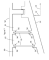
- Figure 2 shows a membrane seal 10 with a different anti-fretting ring 30.
- the face 32 of the anti-fretting ring shown in Figure 1 is convex with a single convex portion; the membrane seal of Figure 2 has a first convex portion 34 and a second convex portion 36.
- the first convex portion 34 is in contact with the membrane 20, and the second convex portion 36 is spaced apart from the membrane 20.
- the first convex portion 34 When in use, the first convex portion 34 may become worn as shown in Figure 3 . After a certain amount of wear of the first convex portion 34, the second convex portion 36 is also in contact with the membrane.
- Figure 4 shows a membrane seal in which the membrane 20 has two anti-fretting rings 30, one arranged adjacent to a first face 22 of the membrane and the other adjacent to a second face 24 of the membrane.
- the first face 22 faces in the opposite direction to the second face 24.
- Both anti-fretting rings are attached to the first gas turbine component 40.
- Figure 5 shows a membrane seal in which the membrane has two anti-fretting rings on the same face, arranged at opposite ends (first end 26 and second end 28) of the membrane in a radial direction 42 relative to a longitudinal gas turbine axis (which extends in an axial direction 44).
- the first anti-fretting ring 30 is attached to a first gas turbine component 40
- the second anti-fretting ring 31 is attached to a second gas turbine component 41.
- Figure 6 shows a perspective view of part of a membrane, showing the curvature of the anti-fretting ring 30 and the first gas turbine component in the circumferential direction 46.
- Figure 7 shows a turbine housing 50 and a turbine vane carrier 52.
- Two membranes 20 extend between the turbine housing 50 and the turbine vane carrier 52.
- an anti-fretting ring could be arranged between a membrane and an adjacent gas turbine component (turbine housing or turbine vane carrier); these are indicated with the reference numeral 56.
- FIG 8 shows a turbine vane carrier 52 and a combustor liner carrier 54.
- a membrane 20 extends between the turbine vane carrier 52 and the combustor liner carrier 54.
- the places where an anti-fretting ring could be arranged between the membrane and an adjacent gas turbine component are indicated with the reference numeral 56.
- a more detailed example of where a membrane seal is located is given with reference to Figure 7 .
- a cavity is divided into three parts 60, 62, 64 by the two membrane seals 10.
- the first part 60 is at a higher pressure from the second part 62
- the second part is at a higher pressure than the third part 64.
- the membrane seal between the second part and the third part for example, is pushed towards the third cavity 64 by the pressure in the second cavity 62.
- Planar cross sections are shown in most of the Figures, extending in the radial direction 42 and the axial direction 44.
- the parts described in this application also extend in a circumferential direction 46 relative to a central axis, which would normally be the longitudinal gas turbine axis (extending in the axial direction 44) around which the rotating parts of the gas turbine rotate.
- the membranes and the anti-fretting rings normally extend in a circumferential direction 46, and each can either be a full ring or ring segments.
- the membrane 20 may be a flat plate. That is, the membrane may be planar, normally extending in the radial direction 42 and the circumferential direction 46.
- the membrane separates two volumes and extends from a first gas turbine component to a second gas turbine component.
- the anti-fretting part 30 may be a ring or a ring section or any other appropriate shape. In the examples shown in Figures 7 and 8 , the anti-fretting part would normally be a ring or a ring section.
- the anti-fretting rings 30 described herein are attached to gas turbine components, and are shown in cavities within the gas turbine components. Variations in this design are possible; for example, an anti-fretting ring may alternatively be attached directly to the surface of a gas turbine component rather than in a cavity.
- anti-fretting rings only a single anti-fretting ring is necessary, for example in a location where there is a particular problem with rubbing.
- the second anti-fretting ring 31 and the face 33 of the second anti-fretting ring are equivalent to the anti-fretting ring 30 and the face 32 of the anti-fretting ring 30 as described in this application, and may have the same designs and design variations.
- the face 32 of the anti-fretting ring is adjacent to a face of the membrane, and is preferably in contact with the face of the membrane.
- the face 32 of the anti-fretting rings described herein is convex. This effectively means that the face is not planar, and that it bulges outwards from the body of the anti-fretting ring. As a result, only a portion of the face 32, 33 can be in contact with the adjacent membrane when the anti-fretting ring is newly installed.
- the convex face of the anti-fretting ring will normally be curved in the radial direction 42 so that when the gas turbine is in use and the gas turbine components are moving relative to one another the membrane moves relative to the face.
- the shape of the face of the anti-fretting ring normally remains constant, as shown in Figure 6 .
- the anti-fretting ring is preferably made of a softer material than the membrane.
- an anti-fretting ring and the membrane may be made of different types of steel, such as an anti-fretting ring made of low alloy steel (content other than iron and carbon: 4% or less by weight) and a membrane made of high alloy steel (content other than iron and carbon: higher than 4% by weight).
- the entire anti-fretting ring can be made of a softer material than the membrane.
- just the face of the anti-fretting ring can be made of a softer material than the membrane, with the rest of the anti-fretting ring being made of a different material.
- the contact surface of the membrane can be nitrated/carburized to present a relative higher strength on the face of the membrane than on than anti-fretting ring.
- the Mohs Scale may be used to measure the relative hardness of the materials.
- the first and second convex portions are generally at different points in the radial direction 42 (so at different distances from the gas turbine axis), and can also be adjacent in the radial direction 42.
- the convex portion 34 closest to the end of the membrane is the portion closest to the membrane, but the other convex portion 32 could alternatively be the portion closest to the membrane. Examples with one or two convex portions are shown above, but three or more convex portions may also be provided.
- the second convex portion is normally further from the membrane than the first convex portion.
- the convex portions When more than two convex portions are provided, the convex portions would normally all be at a different distance from the membrane than each other. Each convex portion effectively has a peak, and once the peak of one convex portion has worn down then the peak of the next convex portion can come into contact with the membrane.
- both anti-fretting rings are normally attached to the same gas turbine component (first gas turbine component 40).
- the membrane seals described in this application can be used in various places in a gas turbine, including those shown in Figures 7 and 8 and also elsewhere, for example between other inner casings and outer casings in a gas turbine.
- the membrane seals can be fitted into a new gas turbine or retrofitted into an existing gas turbine by removing an existing membrane seal and inserting a membrane seal as described herein.
- Membrane seals can be used to separate various cavities, such as those with different pressures, temperatures or contents (e.g. two different gases).
- the cavities being separated are normally between two components that may move relative to one another; the relative movement means that a seal is required that allows relative movement of the two components.
- the first gas turbine component 40 and second gas turbine component 41 can be various components, including those shown in Figures 7 and 8 (turbine housing 50, turbine vane carrier 52, combustor liner carrier 54), and the first and second gas turbine components can normally move relative to one another during use of a gas turbine.
- a gas turbine comprises a compressor, a combustor and a turbine, and may also comprise various other parts, such as a turbine housing, a turbine vane carrier and a combustor liner carrier.
- the combustor liner carrier 54 may be an outer liner carrier for a sequential environmental (SEV) combustor.
Landscapes
- Engineering & Computer Science (AREA)
- General Engineering & Computer Science (AREA)
- Mechanical Engineering (AREA)
- Chemical & Material Sciences (AREA)
- Combustion & Propulsion (AREA)
- Turbine Rotor Nozzle Sealing (AREA)
- Supercharger (AREA)
- Gasket Seals (AREA)
Priority Applications (4)
| Application Number | Priority Date | Filing Date | Title |
|---|---|---|---|
| EP15181039.7A EP3130759B1 (fr) | 2015-08-14 | 2015-08-14 | Joint à membrane de turbine à gaz |
| JP2016158872A JP2017040269A (ja) | 2015-08-14 | 2016-08-12 | ガスタービンダイヤフラムシール |
| CN201610659625.8A CN106468183B (zh) | 2015-08-14 | 2016-08-12 | 燃气涡轮机膜密封件 |
| US15/237,145 US10533442B2 (en) | 2015-08-14 | 2016-08-15 | Gas turbine membrane seal |
Applications Claiming Priority (1)
| Application Number | Priority Date | Filing Date | Title |
|---|---|---|---|
| EP15181039.7A EP3130759B1 (fr) | 2015-08-14 | 2015-08-14 | Joint à membrane de turbine à gaz |
Publications (2)
| Publication Number | Publication Date |
|---|---|
| EP3130759A1 true EP3130759A1 (fr) | 2017-02-15 |
| EP3130759B1 EP3130759B1 (fr) | 2018-12-05 |
Family
ID=53836497
Family Applications (1)
| Application Number | Title | Priority Date | Filing Date |
|---|---|---|---|
| EP15181039.7A Active EP3130759B1 (fr) | 2015-08-14 | 2015-08-14 | Joint à membrane de turbine à gaz |
Country Status (4)
| Country | Link |
|---|---|
| US (1) | US10533442B2 (fr) |
| EP (1) | EP3130759B1 (fr) |
| JP (1) | JP2017040269A (fr) |
| CN (1) | CN106468183B (fr) |
Cited By (1)
| Publication number | Priority date | Publication date | Assignee | Title |
|---|---|---|---|---|
| EP3379036A1 (fr) * | 2017-03-22 | 2018-09-26 | Ansaldo Energia Switzerland AG | Moteur à turbine à gaz et procédé de refroidissement dudit moteur à turbine à gaz |
Families Citing this family (1)
| Publication number | Priority date | Publication date | Assignee | Title |
|---|---|---|---|---|
| FR3081974B1 (fr) * | 2018-06-04 | 2020-06-19 | Safran Aircraft Engines | Chambre de combustion d'une turbomachine |
Citations (4)
| Publication number | Priority date | Publication date | Assignee | Title |
|---|---|---|---|---|
| US2875917A (en) * | 1956-07-02 | 1959-03-03 | North American Aviation Inc | High temperature spring seal |
| GB2396193A (en) * | 2002-12-10 | 2004-06-16 | Alstom Technology Ltd | A seal arrangement for sealing the junction between two parts f the housing of a gas turbine |
| US6857849B2 (en) | 2001-12-22 | 2005-02-22 | Alston Technology Ltd. | Membrane seals |
| EP2813670A2 (fr) * | 2013-05-27 | 2014-12-17 | Kabushiki Kaisha Toshiba | Structure d'étanchéité entre parties fixes |
Family Cites Families (28)
| Publication number | Priority date | Publication date | Assignee | Title |
|---|---|---|---|---|
| US3304360A (en) * | 1964-06-03 | 1967-02-14 | Bell Telephone Labor Inc | Radio frequency gasket for shielded enclosures |
| US4537024A (en) * | 1979-04-23 | 1985-08-27 | Solar Turbines, Incorporated | Turbine engines |
| US4746129A (en) * | 1987-09-14 | 1988-05-24 | Puccio Guy S | Expansion joint strip seal |
| US5624227A (en) * | 1995-11-07 | 1997-04-29 | General Electric Co. | Seal for gas turbines |
| US5716158A (en) * | 1996-08-23 | 1998-02-10 | The Atlantic Group, Inc. | Expandable belt type expansion joint |
| US5823741A (en) * | 1996-09-25 | 1998-10-20 | General Electric Co. | Cooling joint connection for abutting segments in a gas turbine engine |
| WO1998055736A1 (fr) * | 1997-06-04 | 1998-12-10 | Mitsubishi Heavy Industries, Ltd. | Structure d'etancheite montee entre les disques d'une turbine a gaz |
| US6431825B1 (en) * | 2000-07-28 | 2002-08-13 | Alstom (Switzerland) Ltd | Seal between static turbine parts |
| US6722850B2 (en) * | 2002-07-22 | 2004-04-20 | General Electric Company | Endface gap sealing of steam turbine packing seal segments and retrofitting thereof |
| JP4495481B2 (ja) * | 2004-02-18 | 2010-07-07 | イーグル・エンジニアリング・エアロスペース株式会社 | シール装置 |
| US7334800B2 (en) * | 2004-10-29 | 2008-02-26 | Power Systems Mfg., Llc | Seal for a gas turbine engine having improved flexibility |
| BRPI0502980A (pt) * | 2005-07-20 | 2007-03-06 | Mahle Metal Leve Sa | anel de controle de óleo para motor de combustão interna |
| US7788932B2 (en) * | 2005-08-23 | 2010-09-07 | Mitsubishi Heavy Industries, Ltd. | Seal structure for gas turbine combustor |
| GB2434184B (en) * | 2006-01-12 | 2007-12-12 | Rolls Royce Plc | A sealing arrangement |
| JP4663538B2 (ja) * | 2006-01-31 | 2011-04-06 | 日本バルカー工業株式会社 | あり溝用シール材およびあり溝用シール材が装着された真空用ゲート弁 |
| JP4690905B2 (ja) * | 2006-02-17 | 2011-06-01 | 三菱重工業株式会社 | シール装置及び該装置を備えたガスタービン |
| US7527472B2 (en) * | 2006-08-24 | 2009-05-05 | Siemens Energy, Inc. | Thermally sprayed conformal seal |
| US7771171B2 (en) * | 2006-12-14 | 2010-08-10 | General Electric Company | Systems for preventing wear on turbine blade tip shrouds |
| GB2449493B (en) * | 2007-05-25 | 2009-08-12 | Rolls Royce Plc | Vibration damper assembly |
| US8821114B2 (en) * | 2010-06-04 | 2014-09-02 | Siemens Energy, Inc. | Gas turbine engine sealing structure |
| US9017015B2 (en) * | 2011-10-27 | 2015-04-28 | General Electric Company | Turbomachine including an inner-to-outer turbine casing seal assembly and method |
| US8459041B2 (en) * | 2011-11-09 | 2013-06-11 | General Electric Company | Leaf seal for transition duct in turbine system |
| JP6133416B2 (ja) * | 2012-06-18 | 2017-05-24 | ゼネラル エレクトリック テクノロジー ゲゼルシャフト ミット ベシュレンクテル ハフツングGeneral Electric Technology GmbH | タービンの静止した部品間のシール |
| US9243510B2 (en) * | 2012-09-10 | 2016-01-26 | General Electric Company | Floating seal |
| US9714580B2 (en) * | 2013-07-24 | 2017-07-25 | United Technologies Corporation | Trough seal for gas turbine engine |
| EP3039269B1 (fr) * | 2013-08-29 | 2020-05-06 | United Technologies Corporation | Turbine à gaz et procédé de montage |
| EP2886802B1 (fr) * | 2013-12-20 | 2019-04-10 | Safran Aero Boosters SA | Joint de virole interne de dernier étage de compresseur de turbomachine axiale |
| US10107129B2 (en) * | 2016-03-16 | 2018-10-23 | United Technologies Corporation | Blade outer air seal with spring centering |
-
2015
- 2015-08-14 EP EP15181039.7A patent/EP3130759B1/fr active Active
-
2016
- 2016-08-12 JP JP2016158872A patent/JP2017040269A/ja active Pending
- 2016-08-12 CN CN201610659625.8A patent/CN106468183B/zh active Active
- 2016-08-15 US US15/237,145 patent/US10533442B2/en active Active
Patent Citations (4)
| Publication number | Priority date | Publication date | Assignee | Title |
|---|---|---|---|---|
| US2875917A (en) * | 1956-07-02 | 1959-03-03 | North American Aviation Inc | High temperature spring seal |
| US6857849B2 (en) | 2001-12-22 | 2005-02-22 | Alston Technology Ltd. | Membrane seals |
| GB2396193A (en) * | 2002-12-10 | 2004-06-16 | Alstom Technology Ltd | A seal arrangement for sealing the junction between two parts f the housing of a gas turbine |
| EP2813670A2 (fr) * | 2013-05-27 | 2014-12-17 | Kabushiki Kaisha Toshiba | Structure d'étanchéité entre parties fixes |
Cited By (1)
| Publication number | Priority date | Publication date | Assignee | Title |
|---|---|---|---|---|
| EP3379036A1 (fr) * | 2017-03-22 | 2018-09-26 | Ansaldo Energia Switzerland AG | Moteur à turbine à gaz et procédé de refroidissement dudit moteur à turbine à gaz |
Also Published As
| Publication number | Publication date |
|---|---|
| CN106468183B (zh) | 2021-05-28 |
| US10533442B2 (en) | 2020-01-14 |
| CN106468183A (zh) | 2017-03-01 |
| JP2017040269A (ja) | 2017-02-23 |
| EP3130759B1 (fr) | 2018-12-05 |
| US20170044916A1 (en) | 2017-02-16 |
Similar Documents
| Publication | Publication Date | Title |
|---|---|---|
| EP3517807B1 (fr) | Presse-étoupe de bague d'étanchéité individuel | |
| EP1777376B1 (fr) | Joint d'étanchéité inter-arbres tandem en graphite | |
| EP2567072B1 (fr) | Garniture d'étanchéité avec joint annulaire à brosses | |
| US20160245406A1 (en) | Seal and method of manufacturing and/or using same | |
| US12209670B2 (en) | Piston ring for a piston compressor | |
| US12253174B2 (en) | Abradable seal | |
| EP3130759B1 (fr) | Joint à membrane de turbine à gaz | |
| EP2133606B1 (fr) | Cassette et procédés associés | |
| EP3798426B1 (fr) | Ensemble de joint de carbone | |
| US20120155953A1 (en) | Seal ring stabilization system and associated pin joint assembly | |
| US20150110620A1 (en) | Seal arrangement | |
| US11391377B2 (en) | Hydraulic seal |
Legal Events
| Date | Code | Title | Description |
|---|---|---|---|
| PUAI | Public reference made under article 153(3) epc to a published international application that has entered the european phase |
Free format text: ORIGINAL CODE: 0009012 |
|
| STAA | Information on the status of an ep patent application or granted ep patent |
Free format text: STATUS: THE APPLICATION HAS BEEN PUBLISHED |
|
| AK | Designated contracting states |
Kind code of ref document: A1 Designated state(s): AL AT BE BG CH CY CZ DE DK EE ES FI FR GB GR HR HU IE IS IT LI LT LU LV MC MK MT NL NO PL PT RO RS SE SI SK SM TR |
|
| AX | Request for extension of the european patent |
Extension state: BA ME |
|
| RAP1 | Party data changed (applicant data changed or rights of an application transferred) |
Owner name: ANSALDO ENERGIA SWITZERLAND AG |
|
| STAA | Information on the status of an ep patent application or granted ep patent |
Free format text: STATUS: REQUEST FOR EXAMINATION WAS MADE |
|
| 17P | Request for examination filed |
Effective date: 20170816 |
|
| RBV | Designated contracting states (corrected) |
Designated state(s): AL AT BE BG CH CY CZ DE DK EE ES FI FR GB GR HR HU IE IS IT LI LT LU LV MC MK MT NL NO PL PT RO RS SE SI SK SM TR |
|
| RIC1 | Information provided on ipc code assigned before grant |
Ipc: F16J 15/02 20060101ALI20180517BHEP Ipc: F01D 11/00 20060101AFI20180517BHEP |
|
| GRAP | Despatch of communication of intention to grant a patent |
Free format text: ORIGINAL CODE: EPIDOSNIGR1 |
|
| STAA | Information on the status of an ep patent application or granted ep patent |
Free format text: STATUS: GRANT OF PATENT IS INTENDED |
|
| INTG | Intention to grant announced |
Effective date: 20180629 |
|
| GRAS | Grant fee paid |
Free format text: ORIGINAL CODE: EPIDOSNIGR3 |
|
| GRAA | (expected) grant |
Free format text: ORIGINAL CODE: 0009210 |
|
| STAA | Information on the status of an ep patent application or granted ep patent |
Free format text: STATUS: THE PATENT HAS BEEN GRANTED |
|
| AK | Designated contracting states |
Kind code of ref document: B1 Designated state(s): AL AT BE BG CH CY CZ DE DK EE ES FI FR GB GR HR HU IE IS IT LI LT LU LV MC MK MT NL NO PL PT RO RS SE SI SK SM TR |
|
| REG | Reference to a national code |
Ref country code: GB Ref legal event code: FG4D |
|
| REG | Reference to a national code |
Ref country code: CH Ref legal event code: EP |
|
| REG | Reference to a national code |
Ref country code: AT Ref legal event code: REF Ref document number: 1073337 Country of ref document: AT Kind code of ref document: T Effective date: 20181215 |
|
| REG | Reference to a national code |
Ref country code: IE Ref legal event code: FG4D |
|
| REG | Reference to a national code |
Ref country code: DE Ref legal event code: R096 Ref document number: 602015020754 Country of ref document: DE |
|
| REG | Reference to a national code |
Ref country code: NL Ref legal event code: MP Effective date: 20181205 |
|
| REG | Reference to a national code |
Ref country code: AT Ref legal event code: MK05 Ref document number: 1073337 Country of ref document: AT Kind code of ref document: T Effective date: 20181205 |
|
| REG | Reference to a national code |
Ref country code: LT Ref legal event code: MG4D |
|
| PG25 | Lapsed in a contracting state [announced via postgrant information from national office to epo] |
Ref country code: FI Free format text: LAPSE BECAUSE OF FAILURE TO SUBMIT A TRANSLATION OF THE DESCRIPTION OR TO PAY THE FEE WITHIN THE PRESCRIBED TIME-LIMIT Effective date: 20181205 Ref country code: NO Free format text: LAPSE BECAUSE OF FAILURE TO SUBMIT A TRANSLATION OF THE DESCRIPTION OR TO PAY THE FEE WITHIN THE PRESCRIBED TIME-LIMIT Effective date: 20190305 Ref country code: AT Free format text: LAPSE BECAUSE OF FAILURE TO SUBMIT A TRANSLATION OF THE DESCRIPTION OR TO PAY THE FEE WITHIN THE PRESCRIBED TIME-LIMIT Effective date: 20181205 Ref country code: LV Free format text: LAPSE BECAUSE OF FAILURE TO SUBMIT A TRANSLATION OF THE DESCRIPTION OR TO PAY THE FEE WITHIN THE PRESCRIBED TIME-LIMIT Effective date: 20181205 Ref country code: LT Free format text: LAPSE BECAUSE OF FAILURE TO SUBMIT A TRANSLATION OF THE DESCRIPTION OR TO PAY THE FEE WITHIN THE PRESCRIBED TIME-LIMIT Effective date: 20181205 Ref country code: HR Free format text: LAPSE BECAUSE OF FAILURE TO SUBMIT A TRANSLATION OF THE DESCRIPTION OR TO PAY THE FEE WITHIN THE PRESCRIBED TIME-LIMIT Effective date: 20181205 Ref country code: ES Free format text: LAPSE BECAUSE OF FAILURE TO SUBMIT A TRANSLATION OF THE DESCRIPTION OR TO PAY THE FEE WITHIN THE PRESCRIBED TIME-LIMIT Effective date: 20181205 Ref country code: BG Free format text: LAPSE BECAUSE OF FAILURE TO SUBMIT A TRANSLATION OF THE DESCRIPTION OR TO PAY THE FEE WITHIN THE PRESCRIBED TIME-LIMIT Effective date: 20190305 |
|
| PG25 | Lapsed in a contracting state [announced via postgrant information from national office to epo] |
Ref country code: AL Free format text: LAPSE BECAUSE OF FAILURE TO SUBMIT A TRANSLATION OF THE DESCRIPTION OR TO PAY THE FEE WITHIN THE PRESCRIBED TIME-LIMIT Effective date: 20181205 Ref country code: GR Free format text: LAPSE BECAUSE OF FAILURE TO SUBMIT A TRANSLATION OF THE DESCRIPTION OR TO PAY THE FEE WITHIN THE PRESCRIBED TIME-LIMIT Effective date: 20190306 Ref country code: SE Free format text: LAPSE BECAUSE OF FAILURE TO SUBMIT A TRANSLATION OF THE DESCRIPTION OR TO PAY THE FEE WITHIN THE PRESCRIBED TIME-LIMIT Effective date: 20181205 Ref country code: RS Free format text: LAPSE BECAUSE OF FAILURE TO SUBMIT A TRANSLATION OF THE DESCRIPTION OR TO PAY THE FEE WITHIN THE PRESCRIBED TIME-LIMIT Effective date: 20181205 |
|
| PG25 | Lapsed in a contracting state [announced via postgrant information from national office to epo] |
Ref country code: NL Free format text: LAPSE BECAUSE OF FAILURE TO SUBMIT A TRANSLATION OF THE DESCRIPTION OR TO PAY THE FEE WITHIN THE PRESCRIBED TIME-LIMIT Effective date: 20181205 |
|
| PG25 | Lapsed in a contracting state [announced via postgrant information from national office to epo] |
Ref country code: IT Free format text: LAPSE BECAUSE OF FAILURE TO SUBMIT A TRANSLATION OF THE DESCRIPTION OR TO PAY THE FEE WITHIN THE PRESCRIBED TIME-LIMIT Effective date: 20181205 Ref country code: CZ Free format text: LAPSE BECAUSE OF FAILURE TO SUBMIT A TRANSLATION OF THE DESCRIPTION OR TO PAY THE FEE WITHIN THE PRESCRIBED TIME-LIMIT Effective date: 20181205 Ref country code: PT Free format text: LAPSE BECAUSE OF FAILURE TO SUBMIT A TRANSLATION OF THE DESCRIPTION OR TO PAY THE FEE WITHIN THE PRESCRIBED TIME-LIMIT Effective date: 20190405 Ref country code: PL Free format text: LAPSE BECAUSE OF FAILURE TO SUBMIT A TRANSLATION OF THE DESCRIPTION OR TO PAY THE FEE WITHIN THE PRESCRIBED TIME-LIMIT Effective date: 20181205 |
|
| PG25 | Lapsed in a contracting state [announced via postgrant information from national office to epo] |
Ref country code: EE Free format text: LAPSE BECAUSE OF FAILURE TO SUBMIT A TRANSLATION OF THE DESCRIPTION OR TO PAY THE FEE WITHIN THE PRESCRIBED TIME-LIMIT Effective date: 20181205 Ref country code: SM Free format text: LAPSE BECAUSE OF FAILURE TO SUBMIT A TRANSLATION OF THE DESCRIPTION OR TO PAY THE FEE WITHIN THE PRESCRIBED TIME-LIMIT Effective date: 20181205 Ref country code: SK Free format text: LAPSE BECAUSE OF FAILURE TO SUBMIT A TRANSLATION OF THE DESCRIPTION OR TO PAY THE FEE WITHIN THE PRESCRIBED TIME-LIMIT Effective date: 20181205 Ref country code: IS Free format text: LAPSE BECAUSE OF FAILURE TO SUBMIT A TRANSLATION OF THE DESCRIPTION OR TO PAY THE FEE WITHIN THE PRESCRIBED TIME-LIMIT Effective date: 20190405 Ref country code: RO Free format text: LAPSE BECAUSE OF FAILURE TO SUBMIT A TRANSLATION OF THE DESCRIPTION OR TO PAY THE FEE WITHIN THE PRESCRIBED TIME-LIMIT Effective date: 20181205 |
|
| REG | Reference to a national code |
Ref country code: DE Ref legal event code: R097 Ref document number: 602015020754 Country of ref document: DE |
|
| PLBE | No opposition filed within time limit |
Free format text: ORIGINAL CODE: 0009261 |
|
| STAA | Information on the status of an ep patent application or granted ep patent |
Free format text: STATUS: NO OPPOSITION FILED WITHIN TIME LIMIT |
|
| PG25 | Lapsed in a contracting state [announced via postgrant information from national office to epo] |
Ref country code: DK Free format text: LAPSE BECAUSE OF FAILURE TO SUBMIT A TRANSLATION OF THE DESCRIPTION OR TO PAY THE FEE WITHIN THE PRESCRIBED TIME-LIMIT Effective date: 20181205 Ref country code: SI Free format text: LAPSE BECAUSE OF FAILURE TO SUBMIT A TRANSLATION OF THE DESCRIPTION OR TO PAY THE FEE WITHIN THE PRESCRIBED TIME-LIMIT Effective date: 20181205 |
|
| 26N | No opposition filed |
Effective date: 20190906 |
|
| PG25 | Lapsed in a contracting state [announced via postgrant information from national office to epo] |
Ref country code: TR Free format text: LAPSE BECAUSE OF FAILURE TO SUBMIT A TRANSLATION OF THE DESCRIPTION OR TO PAY THE FEE WITHIN THE PRESCRIBED TIME-LIMIT Effective date: 20181205 |
|
| GBPC | Gb: european patent ceased through non-payment of renewal fee |
Effective date: 20190814 |
|
| PG25 | Lapsed in a contracting state [announced via postgrant information from national office to epo] |
Ref country code: LI Free format text: LAPSE BECAUSE OF NON-PAYMENT OF DUE FEES Effective date: 20190831 Ref country code: CH Free format text: LAPSE BECAUSE OF NON-PAYMENT OF DUE FEES Effective date: 20190831 Ref country code: MC Free format text: LAPSE BECAUSE OF FAILURE TO SUBMIT A TRANSLATION OF THE DESCRIPTION OR TO PAY THE FEE WITHIN THE PRESCRIBED TIME-LIMIT Effective date: 20181205 Ref country code: LU Free format text: LAPSE BECAUSE OF NON-PAYMENT OF DUE FEES Effective date: 20190814 |
|
| REG | Reference to a national code |
Ref country code: BE Ref legal event code: MM Effective date: 20190831 |
|
| PG25 | Lapsed in a contracting state [announced via postgrant information from national office to epo] |
Ref country code: FR Free format text: LAPSE BECAUSE OF NON-PAYMENT OF DUE FEES Effective date: 20190831 Ref country code: IE Free format text: LAPSE BECAUSE OF NON-PAYMENT OF DUE FEES Effective date: 20190814 |
|
| PG25 | Lapsed in a contracting state [announced via postgrant information from national office to epo] |
Ref country code: BE Free format text: LAPSE BECAUSE OF NON-PAYMENT OF DUE FEES Effective date: 20190831 Ref country code: GB Free format text: LAPSE BECAUSE OF NON-PAYMENT OF DUE FEES Effective date: 20190814 |
|
| PG25 | Lapsed in a contracting state [announced via postgrant information from national office to epo] |
Ref country code: CY Free format text: LAPSE BECAUSE OF FAILURE TO SUBMIT A TRANSLATION OF THE DESCRIPTION OR TO PAY THE FEE WITHIN THE PRESCRIBED TIME-LIMIT Effective date: 20181205 |
|
| PG25 | Lapsed in a contracting state [announced via postgrant information from national office to epo] |
Ref country code: MT Free format text: LAPSE BECAUSE OF FAILURE TO SUBMIT A TRANSLATION OF THE DESCRIPTION OR TO PAY THE FEE WITHIN THE PRESCRIBED TIME-LIMIT Effective date: 20181205 Ref country code: HU Free format text: LAPSE BECAUSE OF FAILURE TO SUBMIT A TRANSLATION OF THE DESCRIPTION OR TO PAY THE FEE WITHIN THE PRESCRIBED TIME-LIMIT; INVALID AB INITIO Effective date: 20150814 |
|
| PG25 | Lapsed in a contracting state [announced via postgrant information from national office to epo] |
Ref country code: MK Free format text: LAPSE BECAUSE OF FAILURE TO SUBMIT A TRANSLATION OF THE DESCRIPTION OR TO PAY THE FEE WITHIN THE PRESCRIBED TIME-LIMIT Effective date: 20181205 |
|
| P01 | Opt-out of the competence of the unified patent court (upc) registered |
Effective date: 20240430 |
|
| PGFP | Annual fee paid to national office [announced via postgrant information from national office to epo] |
Ref country code: DE Payment date: 20250819 Year of fee payment: 11 |