EP3130830A1 - Bride de liaison comprenant une liaison debordante par force et ajustement de forme - Google Patents
Bride de liaison comprenant une liaison debordante par force et ajustement de forme Download PDFInfo
- Publication number
- EP3130830A1 EP3130830A1 EP16001165.6A EP16001165A EP3130830A1 EP 3130830 A1 EP3130830 A1 EP 3130830A1 EP 16001165 A EP16001165 A EP 16001165A EP 3130830 A1 EP3130830 A1 EP 3130830A1
- Authority
- EP
- European Patent Office
- Prior art keywords
- flange
- sleeve
- flanges
- positive
- screws
- Prior art date
- Legal status (The legal status is an assumption and is not a legal conclusion. Google has not performed a legal analysis and makes no representation as to the accuracy of the status listed.)
- Withdrawn
Links
- 238000010008 shearing Methods 0.000 claims abstract description 11
- 230000005540 biological transmission Effects 0.000 claims abstract description 4
- 125000006850 spacer group Chemical group 0.000 claims description 16
- 238000007789 sealing Methods 0.000 claims description 6
- 239000000853 adhesive Substances 0.000 claims description 3
- 230000001070 adhesive effect Effects 0.000 claims description 3
- 238000009826 distribution Methods 0.000 claims description 2
- 239000007769 metal material Substances 0.000 claims description 2
- 230000002093 peripheral effect Effects 0.000 claims description 2
- 230000008030 elimination Effects 0.000 claims 2
- 238000003379 elimination reaction Methods 0.000 claims 2
- 230000002265 prevention Effects 0.000 claims 2
- 230000003068 static effect Effects 0.000 abstract description 4
- 238000000926 separation method Methods 0.000 abstract description 3
- 238000003466 welding Methods 0.000 abstract description 3
- XLYOFNOQVPJJNP-UHFFFAOYSA-N water Substances O XLYOFNOQVPJJNP-UHFFFAOYSA-N 0.000 abstract description 2
- 238000004519 manufacturing process Methods 0.000 description 4
- 230000000694 effects Effects 0.000 description 3
- 240000006829 Ficus sundaica Species 0.000 description 2
- 241000209035 Ilex Species 0.000 description 2
- 238000005452 bending Methods 0.000 description 2
- 238000004364 calculation method Methods 0.000 description 2
- 230000008859 change Effects 0.000 description 2
- 230000003750 conditioning effect Effects 0.000 description 2
- 239000000463 material Substances 0.000 description 2
- 238000006798 ring closing metathesis reaction Methods 0.000 description 2
- 229910000851 Alloy steel Inorganic materials 0.000 description 1
- 241000701193 Mutellina purpurea Species 0.000 description 1
- 238000004458 analytical method Methods 0.000 description 1
- 150000001875 compounds Chemical class 0.000 description 1
- 230000006835 compression Effects 0.000 description 1
- 238000007906 compression Methods 0.000 description 1
- 238000010276 construction Methods 0.000 description 1
- 238000004880 explosion Methods 0.000 description 1
- 238000009434 installation Methods 0.000 description 1
- 239000007788 liquid Substances 0.000 description 1
- 239000002184 metal Substances 0.000 description 1
- 238000000034 method Methods 0.000 description 1
- 230000008569 process Effects 0.000 description 1
- 238000003892 spreading Methods 0.000 description 1
- 230000007480 spreading Effects 0.000 description 1
- 239000000126 substance Substances 0.000 description 1
- 230000007704 transition Effects 0.000 description 1
- 238000010200 validation analysis Methods 0.000 description 1
- 238000012795 verification Methods 0.000 description 1
Images

Classifications
-
- F—MECHANICAL ENGINEERING; LIGHTING; HEATING; WEAPONS; BLASTING
- F16—ENGINEERING ELEMENTS AND UNITS; GENERAL MEASURES FOR PRODUCING AND MAINTAINING EFFECTIVE FUNCTIONING OF MACHINES OR INSTALLATIONS; THERMAL INSULATION IN GENERAL
- F16L—PIPES; JOINTS OR FITTINGS FOR PIPES; SUPPORTS FOR PIPES, CABLES OR PROTECTIVE TUBING; MEANS FOR THERMAL INSULATION IN GENERAL
- F16L23/00—Flanged joints
-
- F—MECHANICAL ENGINEERING; LIGHTING; HEATING; WEAPONS; BLASTING
- F16—ENGINEERING ELEMENTS AND UNITS; GENERAL MEASURES FOR PRODUCING AND MAINTAINING EFFECTIVE FUNCTIONING OF MACHINES OR INSTALLATIONS; THERMAL INSULATION IN GENERAL
- F16L—PIPES; JOINTS OR FITTINGS FOR PIPES; SUPPORTS FOR PIPES, CABLES OR PROTECTIVE TUBING; MEANS FOR THERMAL INSULATION IN GENERAL
- F16L23/00—Flanged joints
- F16L23/003—Auxiliary devices
-
- F—MECHANICAL ENGINEERING; LIGHTING; HEATING; WEAPONS; BLASTING
- F16—ENGINEERING ELEMENTS AND UNITS; GENERAL MEASURES FOR PRODUCING AND MAINTAINING EFFECTIVE FUNCTIONING OF MACHINES OR INSTALLATIONS; THERMAL INSULATION IN GENERAL
- F16L—PIPES; JOINTS OR FITTINGS FOR PIPES; SUPPORTS FOR PIPES, CABLES OR PROTECTIVE TUBING; MEANS FOR THERMAL INSULATION IN GENERAL
- F16L23/00—Flanged joints
- F16L23/02—Flanged joints the flanges being connected by members tensioned axially
- F16L23/036—Flanged joints the flanges being connected by members tensioned axially characterised by the tensioning members, e.g. specially adapted bolts or C-clamps
-
- F—MECHANICAL ENGINEERING; LIGHTING; HEATING; WEAPONS; BLASTING
- F16—ENGINEERING ELEMENTS AND UNITS; GENERAL MEASURES FOR PRODUCING AND MAINTAINING EFFECTIVE FUNCTIONING OF MACHINES OR INSTALLATIONS; THERMAL INSULATION IN GENERAL
- F16L—PIPES; JOINTS OR FITTINGS FOR PIPES; SUPPORTS FOR PIPES, CABLES OR PROTECTIVE TUBING; MEANS FOR THERMAL INSULATION IN GENERAL
- F16L23/00—Flanged joints
- F16L23/16—Flanged joints characterised by the sealing means
- F16L23/24—Flanged joints characterised by the sealing means specially adapted for unequal expansion of the parts of the joint
Definitions
- the invention relates to a releasable connection arrangement in which a flange connection, as used in almost all industrial sectors as a standard component used to clamp with a cross-positive and positive connection.
- the object of the invention is to avoid the classic flange connections recurring leaks in both new plants and to eliminate existing versions, especially without separation and welding on site and permanently exclude for further operation.
- a sleeve engages over a completely clamped with screws flange.
- the sleeve has an encircling groove at one axial end.
- Component tolerances in the region of the groove lead to canting of the segments and consequently to increased edge pressures on the known extremely loaded shear ring closures.
- the shearing segments are clamped to achieve an always full-surface contact with screws on the flange.
- step screw for screw from the fully strained connection to take out, so that the respective segment in the groove of the previously pushed over sleeve and is to be clamped again with the flanges.
- the pre-deformation of the seal is only insignificantly influenced by the removed screw, but the sleeve is fixed in the axial direction.
- the opposite end of the sleeve has a recess with a contact surface for receiving the wedge-shaped clamping elements according to the EP 0 775 863 B1 on.
- the clamping elements are to be arranged between them and the flange spacers. These have either an internal thread and at the same time are part of the Flanschverschraubung or they cover the flange on the protruding screw heads or nuts.
- a negative sealing effect can thus occur neither as a result of screw relaxation nor by destroying the sealing resistance of a seal arranged in the KNS as a result of overpressing.
- This also applies to gaskets in the KHS, which have a sealing surface pressure that is almost constant over a long period of operation due to their relaxation behavior, for example RTJ metal ring joint gaskets. The tightness of the combined connection is thus always given.
- both the previous experience for mounting the classic flange, u.a. when inserting and pre-forming the seal, when using assembly aids with non-aligned flanges to each other and in carrying out required pressure samples in connection with the manufacturing and assembly experience of non-positive and positive connection continue to use advantageous.
- the clamping with the clamping elements takes place only after the clamping process of the original flange, whose function continues to exist unchanged.
- the forces to be applied for pre-forming the gasket are taken into account in the respective verification of the existing flange connection, and consequently with a few exceptions additional calculation proofs and approvals are omitted.
- Both systems can be combined as a primary measure to reduce risk advantageous, with the reasonable economic effort to achieve additional security over the previous versions in a positive relationship.
- spacers are to be arranged on the respective flange for covering the holes for sufficient investment of the wedge-shaped clamping elements.
- one or more parts of a pressure distribution body are provided for producing the largest possible contact surface.
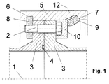
- Fig. 1 shows in combination with a non-positive and positive connection the longitudinal section of a completely braced with screws classic flange connection.
- a sleeve (5) which engages over both flanges, has at one axial end a peripheral groove (6), in which segments (8) loaded with shearing are arranged.
- the segments are braced against the flange (3) with screws (2) to achieve uniform surface loading in the groove (6).
- the faces are in block position against each other.
- a recess with a contact surface (7) is incorporated on the inner contour, are arranged in the wedge-shaped clamping elements (9). These have between their wedge surfaces and their Verspannachse (12) on a self-locking leading adhesive friction angle. Between the clamping elements (9) and the flange (3) are spacer (10). These cover the screw heads / nuts of the screws (2) protruding from the flange. Between the flanges (3), a seal (4) is arranged in the force shunt.
- Fig. 2 shows analogous to FIG. 1 the execution of the spacers (10) with an internal thread. These assume the function of the mother.
- a compensating element (13) is arranged, inter alia, to compensate for manufacturing tolerances for larger diameters.
- the seal (4) with intermediate ring (11) shown as a sealing element.
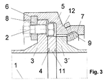
- Fig. 3 shows in a further embodiment, the longitudinal section of a connection assembly for high temperature loaded connections.
- the right flange is designed as a flange collar (3 ').
- the shear segments (8) which are braced with the flange (3), have bores for passing through the screws (2).
- intermediate ring (11) act the seals (4) in the force shunt.
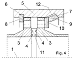
- Fig. 4 shows analogous to FIG. 1 the longitudinal section of a connection arrangement in which a sleeve (5) two flanges (3) overlaps, but which are not clamped together with screws.
- the spacers (10) between the flange (3) and the wedge-shaped clamping elements (9) cover according to claim 5, the holes in the flange (3) to achieve a sufficient investment of the wedge-shaped clamping elements (9).
- an intermediate ring (11) for receiving a plurality of forces acting in the force shunt seals (4) is arranged between the flanges (3).
- the shows Fig. 4 also the embodiment of a compound according to claim 4, in which a sleeve (5) engages over two flange collars (3 ') instead of the flanges (3).
Landscapes
- Engineering & Computer Science (AREA)
- General Engineering & Computer Science (AREA)
- Mechanical Engineering (AREA)
- Clamps And Clips (AREA)
Applications Claiming Priority (1)
| Application Number | Priority Date | Filing Date | Title |
|---|---|---|---|
| DE102015010511.6A DE102015010511B8 (de) | 2015-06-02 | 2015-08-12 | Flanschverbindung mit einer übergreifenden kraft- und formschlüssigen Verbindungsanordnung |
Publications (1)
| Publication Number | Publication Date |
|---|---|
| EP3130830A1 true EP3130830A1 (fr) | 2017-02-15 |
Family
ID=56360145
Family Applications (1)
| Application Number | Title | Priority Date | Filing Date |
|---|---|---|---|
| EP16001165.6A Withdrawn EP3130830A1 (fr) | 2015-08-12 | 2016-05-21 | Bride de liaison comprenant une liaison debordante par force et ajustement de forme |
Country Status (1)
| Country | Link |
|---|---|
| EP (1) | EP3130830A1 (fr) |
Cited By (3)
| Publication number | Priority date | Publication date | Assignee | Title |
|---|---|---|---|---|
| CN114738576A (zh) * | 2022-03-25 | 2022-07-12 | 保定天威保变电气股份有限公司 | 一种利用消防水带的水冷变压器试验装置 |
| CN114754208A (zh) * | 2022-06-16 | 2022-07-15 | 南通希尔顿博世流体设备有限公司 | 一种管道法兰连接装置及使用该连接装置的流体设备 |
| CN116045070A (zh) * | 2023-03-31 | 2023-05-02 | 艾坦姆流体控制技术(山东)有限公司 | 一种球笼式降噪调节阀 |
Citations (6)
| Publication number | Priority date | Publication date | Assignee | Title |
|---|---|---|---|---|
| US1894094A (en) * | 1931-10-28 | 1933-01-10 | Gen Electric | Flange coupling |
| CH488944A (de) * | 1968-03-21 | 1970-04-15 | Sulzer Ag | Vorrichtung zum Befestigen eines Elementes an einem anderen Element, insbesondere für Hochdruckpumpen |
| EP0775863B1 (fr) | 1995-11-25 | 1999-09-15 | Alfred Schlemenat | Connexion amovible des pièces symétriques de révolution |
| DE102012007145A1 (de) | 2012-04-12 | 2013-10-17 | Alfred W. Schlemenat | Lösbare Verbindung von rotationssymmetrischen Bauteilen |
| DE202015004470U1 (de) * | 2015-06-02 | 2015-07-27 | Alfred Wilhelm Schlemenat | Flanschverbindung mit einer übergreifenden kraft- und formschlüssigen Verbindungsanordnung |
| DE202015006063U1 (de) * | 2015-06-02 | 2015-09-21 | Alfred Wilhelm Schlemenat | Flanschverbindung mit einer übergreifenden kraft- und formschlüssigen Verbindungsanordnung |
-
2016
- 2016-05-21 EP EP16001165.6A patent/EP3130830A1/fr not_active Withdrawn
Patent Citations (7)
| Publication number | Priority date | Publication date | Assignee | Title |
|---|---|---|---|---|
| US1894094A (en) * | 1931-10-28 | 1933-01-10 | Gen Electric | Flange coupling |
| CH488944A (de) * | 1968-03-21 | 1970-04-15 | Sulzer Ag | Vorrichtung zum Befestigen eines Elementes an einem anderen Element, insbesondere für Hochdruckpumpen |
| EP0775863B1 (fr) | 1995-11-25 | 1999-09-15 | Alfred Schlemenat | Connexion amovible des pièces symétriques de révolution |
| DE102012007145A1 (de) | 2012-04-12 | 2013-10-17 | Alfred W. Schlemenat | Lösbare Verbindung von rotationssymmetrischen Bauteilen |
| DE202015004470U1 (de) * | 2015-06-02 | 2015-07-27 | Alfred Wilhelm Schlemenat | Flanschverbindung mit einer übergreifenden kraft- und formschlüssigen Verbindungsanordnung |
| DE202015006063U1 (de) * | 2015-06-02 | 2015-09-21 | Alfred Wilhelm Schlemenat | Flanschverbindung mit einer übergreifenden kraft- und formschlüssigen Verbindungsanordnung |
| DE102015010511B3 (de) * | 2015-06-02 | 2015-12-10 | Alfred Wilhelm Schlemenat | Flaschenverbindung mit einer übergreifenden kraft- und formschlüssigen Verbindungsanordnung |
Non-Patent Citations (1)
| Title |
|---|
| "Festigkeitsberechnungen im Dampfkessel-, Behälter- und Rohrleitungsbau", 1978, SPRINGER VERLAG |
Cited By (4)
| Publication number | Priority date | Publication date | Assignee | Title |
|---|---|---|---|---|
| CN114738576A (zh) * | 2022-03-25 | 2022-07-12 | 保定天威保变电气股份有限公司 | 一种利用消防水带的水冷变压器试验装置 |
| CN114754208A (zh) * | 2022-06-16 | 2022-07-15 | 南通希尔顿博世流体设备有限公司 | 一种管道法兰连接装置及使用该连接装置的流体设备 |
| CN114754208B (zh) * | 2022-06-16 | 2022-09-02 | 南通希尔顿博世流体设备有限公司 | 一种管道法兰连接装置及使用该连接装置的流体设备 |
| CN116045070A (zh) * | 2023-03-31 | 2023-05-02 | 艾坦姆流体控制技术(山东)有限公司 | 一种球笼式降噪调节阀 |
Similar Documents
| Publication | Publication Date | Title |
|---|---|---|
| DE102010016557A1 (de) | Rohr- oder Kabeldurchführung zur dichten Durchführung wenigstens eines Rohres oder wenigstens eines Kabels durch eine Wand- oder Deckenplatte | |
| DE19507854B4 (de) | Mehrteilige Dichtungsvorrichtung | |
| EP0775863A1 (fr) | Connexion amovible des pièces symétriques de révolution | |
| EP4179243A1 (fr) | Dispositif de raccordement d'un élément de tuyau de transport de gaz et procédé de raccordement d'un élément de tuyau de transport de gaz | |
| DE102012007145A1 (de) | Lösbare Verbindung von rotationssymmetrischen Bauteilen | |
| DE102015010511B3 (de) | Flaschenverbindung mit einer übergreifenden kraft- und formschlüssigen Verbindungsanordnung | |
| DE60214775T2 (de) | Flanschglied mit einem ersten flanschende, das in einer radialrichtung mit einer konkaven endfläche ausgeführt ist, und einer flanschgliederumfassenden flanschverbindung | |
| EP0087702A1 (fr) | Raccord de tuyaux | |
| EP3397889B1 (fr) | Dispositif de raccordement | |
| EP3683481B1 (fr) | Raccord et pièce d'extension pour conduites | |
| DE102006005259A1 (de) | Verbesserte Druckverbindung für Rohre | |
| DE202015004470U1 (de) | Flanschverbindung mit einer übergreifenden kraft- und formschlüssigen Verbindungsanordnung | |
| DE4211076A1 (de) | Dichtung | |
| EP1248027A1 (fr) | Raccord axial de deux éléments tubulaires | |
| DE202014002608U1 (de) | Flanschverbindung für Rohrleitungen | |
| DE202014001538U1 (de) | Verbindungsanordnung zum Erzielen optimaler Dichtheitsvoraussetzungen | |
| AT405211B (de) | Kunststoff-rohrleitungsteil mit mindestens einem seitenabgang | |
| DE4317256C2 (de) | Rohrverbindung, insbesondere in einer Brennkraftmaschinen-Abgasanlage | |
| EP1783413B1 (fr) | Dispositif pour raccorder les bouts d'un tuyau métallique ondulé hélicoïdalement avec un embout | |
| DE102019122355A1 (de) | Flanschverbindung mit Schweißringdichtung | |
| EP1927804B1 (fr) | Raccord de tuyauterie | |
| DE1234162B (de) | Gasdichte Schraubverbindung fuer OElfeldrohre | |
| DE102015001571A1 (de) | Dichtsystem für eine gesteckte Fluidleitung | |
| DE20003714U1 (de) | Vorrichtung zum Demontieren von miteinander verschraubten Flanschverbindungen | |
| DE102010006891A1 (de) | Verbindung von Platten, insbesondere Flanschen, mit einer Schraube und einer Mutter als Thermokompensator |
Legal Events
| Date | Code | Title | Description |
|---|---|---|---|
| PUAI | Public reference made under article 153(3) epc to a published international application that has entered the european phase |
Free format text: ORIGINAL CODE: 0009012 |
|
| AK | Designated contracting states |
Kind code of ref document: A1 Designated state(s): AL AT BE BG CH CY CZ DE DK EE ES FI FR GB GR HR HU IE IS IT LI LT LU LV MC MK MT NL NO PL PT RO RS SE SI SK SM TR |
|
| AX | Request for extension of the european patent |
Extension state: BA ME |
|
| STAA | Information on the status of an ep patent application or granted ep patent |
Free format text: STATUS: THE APPLICATION IS DEEMED TO BE WITHDRAWN |
|
| 18D | Application deemed to be withdrawn |
Effective date: 20170817 |