EP3130977A1 - Analyse des paramètres de fonctionnement de machines - Google Patents
Analyse des paramètres de fonctionnement de machines Download PDFInfo
- Publication number
- EP3130977A1 EP3130977A1 EP16182960.1A EP16182960A EP3130977A1 EP 3130977 A1 EP3130977 A1 EP 3130977A1 EP 16182960 A EP16182960 A EP 16182960A EP 3130977 A1 EP3130977 A1 EP 3130977A1
- Authority
- EP
- European Patent Office
- Prior art keywords
- operating parameter
- indication
- machine
- ideal curve
- computing device
- Prior art date
- Legal status (The legal status is an assumption and is not a legal conclusion. Google has not performed a legal analysis and makes no representation as to the accuracy of the status listed.)
- Granted
Links
Images





Classifications
-
- G—PHYSICS
- G01—MEASURING; TESTING
- G01M—TESTING STATIC OR DYNAMIC BALANCE OF MACHINES OR STRUCTURES; TESTING OF STRUCTURES OR APPARATUS, NOT OTHERWISE PROVIDED FOR
- G01M99/00—Subject matter not provided for in other groups of this subclass
- G01M99/005—Testing of complete machines, e.g. washing-machines or mobile phones
-
- G—PHYSICS
- G05—CONTROLLING; REGULATING
- G05B—CONTROL OR REGULATING SYSTEMS IN GENERAL; FUNCTIONAL ELEMENTS OF SUCH SYSTEMS; MONITORING OR TESTING ARRANGEMENTS FOR SUCH SYSTEMS OR ELEMENTS
- G05B23/00—Testing or monitoring of control systems or parts thereof
- G05B23/02—Electric testing or monitoring
- G05B23/0205—Electric testing or monitoring by means of a monitoring system capable of detecting and responding to faults
- G05B23/0218—Electric testing or monitoring by means of a monitoring system capable of detecting and responding to faults characterised by the fault detection method dealing with either existing or incipient faults
- G05B23/0256—Electric testing or monitoring by means of a monitoring system capable of detecting and responding to faults characterised by the fault detection method dealing with either existing or incipient faults injecting test signals and analyzing monitored process response, e.g. injecting the test signal while interrupting the normal operation of the monitored system; superimposing the test signal onto a control signal during normal operation of the monitored system
Definitions
- This disclosure generally describes machine condition monitoring, and, some embodiments, analyzing machine operating parameters and presenting the results of the analysis
- the method further can include normalizing the indication of the first operating parameter to the ideal curve of the first operating parameter wherein normalizing the first operating parameter comprises scaling the first operating parameter with respect to the ideal curve and determining a condition of the machine based on the normalizing of the indication of the first operating parameter to the ideal curve of the first operating parameter.
- a machinery analysis system can include a computing device communicatively coupled to a user interface and a memory device.
- the system also can include a thermodynamic model of at least a portion of a machine stored in the memory device wherein the model can be configured to generate an ideal curve of a first operating parameter of the machine that can include a plurality of component parts.
- the system further can include a sensor configured to generate an indication of a second operating parameter of the machine and a sensor configured to generate an indication of the first operating parameter of the machine wherein the indication of the first operating parameter can be correlated to the generated indication of the second operating parameter.
- the computing device can be configured to normalize the indication of the first operating parameter to the ideal curve of the first operating parameter and determine a condition of the machine based on the normalizing of the indication of the first operating parameter to the ideal curve of the first operating parameter.
- one or more non-transitory computer-readable storage media has computer-executable instructions embodied thereon.
- the computer-executable instructions When executed by at least one processor, the computer-executable instructions cause the processor to determine an ideal curve of a first operating parameter of a machine that can include a plurality of component parts.
- the computer-executable instructions also cause the processor to receive an indication of a second operating parameter of the machine and receive an indication of the first operating parameter of the machine that can be correlated to the received indication of the second operating parameter.
- the computer-executable instructions further cause the processor to normalize the indication of the first operating parameter to the ideal curve of the first operating parameter and determine a condition of the machine based on the normalizing of the indication of the first operating parameter to the ideal curve of the first operating parameter.
- Embodiments of the present disclosure describe techniques for improving a presentation of monitored process parameters of a machine.
- a reciprocating compressor includes many components that work together in a precise manner to generate a flow of relatively high pressure gas.
- many of the process parameters of the reciprocating compressor are monitored by physical sensors or by virtual sensors to continuously determine an operating condition of the reciprocating compressor. Some of the monitored process parameters are compared to threshold ranges, outside of which, a monitoring system alerts operators of a potential undesirable condition.
- a monitoring technique which is described in greater detail herein below, uses an ideal representation of one or more of the monitored process parameter to highlight deviations from an expected value predicted by the ideal representation.
- the ideal representation can be embodied in an algorithm, such as, but not limited to a model, a set of rules, a lookup table, or combinations of the above.
- Some conditions of the reciprocating compressor exhibit tell-tail characteristics that can be visualized when the process parameter is plotted along with the ideal representation for that process parameter.
- some embodiments of the disclosed subject matter relate to a condition monitoring system for a reciprocating compressor. Other embodiments are within the scope of the disclosed subject matter.
- FIG. 1 is a schematic illustration of an exemplary reciprocating compressor 10 including a condition monitoring system 12.
- FIG. 2 is a cross-sectional view of reciprocating compressor 10 taken along line 2-2.
- reciprocating compressor 10 can be coupled in flow communication between a gas source 14 and an output assembly 16.
- Reciprocating compressor 10 can receive a flow of fluid such as, for example a gas or a gas mixture, can compress the gas to a higher pressure and a lower volume, and can discharge the compressed gas to output assembly 16.
- one or more fluid inlet conduits 18 can be coupled between gas source 14 and reciprocating compressor 10 for channeling gas from gas source 14 to reciprocating compressor 10.
- one or more fluid outlet conduits 20 can be coupled between reciprocating compressor 10 and output assembly 16 for channeling compressed gas from reciprocating compressor 10 to output assembly 16.
- condition monitoring system 12 can be coupled to reciprocating compressor 10 for monitoring reciprocating compressor 10. More specifically, condition monitoring system 12 can be coupled to reciprocating compressor 10 to enable monitoring of forces acting on the piston, piston position, and cylinder pressure on the head end and crank end.
- Condition monitoring system 12 can include a protection system 22 that can be coupled in communication with a plurality of sensors 24 (communication conduits not shown for clarity). Each sensor 24 can detect various conditions of reciprocating compressor 10. Sensors 24 may include, but are not limited to only including, position sensors, temperature sensors, flow sensors, acceleration sensors, pressure sensors, and/or any other sensors that sense various parameters relative to the operation of reciprocating compressor 10.
- the term "parameters" includes physical properties whose values can be used to define the operating conditions of reciprocating compressor 10, such as vibrations, pressures, and fluid flows at defined locations.
- At least one position sensor 56 can be coupled to compressor frame 28 for sensing a position of crank pin 50 with respect to Y-axis and for transmitting a signal indicative of the sensed position to protection system 22.
- position sensor 56 can include a multi-event wheel for use in sensing a position of crank pin 50 with respect to Y-axis.
- piston assembly 42 translates a rotation of crankshaft 44 about axis 48 into a linear movement of piston head 58 along centerline axis 68.
- Piston rod 60 can be coupled between crosshead 62 and piston head 58, and can be oriented to move piston head 58 along centerline axis 68.
- Connecting rod 64 can extend between crosshead 62 and crank pin 50 and can include a first end 88 and a second end 90.
- First end 88 can be coupled to crank pin 50 and can be pivotable with respect to crank pin 50, as crank pin 50 rotates about axis 48.
- Second end 90 can be coupled to crosshead 62 and can be pivotable with respect to crosshead 62.
- crankshaft 44 rotates about axis 48
- connecting rod 64 pivots with respect to crosshead 62 and can move crosshead 62 along centerline axis 68.
- Crosshead 62 in turn, can move piston rod 60 and piston head 58 longitudinally along centerline axis 68.
- piston head 58 can be reciprocated along centerline axis 68.
- a complete compressor operation cycle of reciprocating compressor 10 can include a full rotation between crank angle ⁇ of 0° to 360°.
- cylinder assembly 26 can include a cylinder head 92, a distance piece 94, and a crosshead guide 96.
- Fastener assemblies 30 can be coupled between cylinder head 92, distance piece 94, and crosshead guide 96 to facilitate coupling cylinder head 92, distance piece 94, and crosshead guide 96 together.
- Distance piece 94 can extend between cylinder head 92 and crosshead guide 96.
- Crosshead guide 96 can be coupled to compressor frame 28 for supporting cylinder assembly 26 from compressor frame 28.
- Cylinder head 92 can include an inner surface 98 that can define a cavity 100.
- Piston head 58 can be positioned within, and can be movable within, cavity 100 along centerline axis 68.
- At least one pressure sensor 116 can be coupled to cylinder assembly 26 for use in sensing a pressure within HE chamber 104 and/or CE chamber 108. Pressure sensor 116 can transmit a signal indicative of fluid pressure to protection system 22.
- condition monitoring system 12 can include a first pressure sensor 118 and a second pressure sensor 120. First pressure sensor 118 can be coupled to HE chamber 104 for sensing a pressure within HE chamber 104, and second pressure sensor 120 can be coupled to CE chamber 108 for sensing a pressure within CE chamber 108.
- HE discharge valve 124 can be movable between an open position that can enable gas to be discharged from HE chamber 104 to output assembly 16 and a closed position that can prevent gas from being discharged from HE chamber 104 to output assembly 16.
- HE suction valve 122 can move to the open position when a pressure within HE chamber 104 can be at a first predefined pressure, and can move to the closed position when the pressure within HE chamber 104 can be above the first pressure.
- HE discharge valve can move to the open position when the pressure within HE chamber can be at a second predefined pressure that can be higher than the first pressure, and can move to the closed position when the pressure can be below the second pressure.
- Cylinder head 92 also can include a CE suction valve 126 and a CE discharge valve 128.
- CE suction valve 126 can be coupled in flow communication between CE chamber 108 and fluid inlet conduit 18 for regulating a flow of gas from gas source 14 to CE chamber 108.
- CE suction valve 126 can be movable between an open position that can enable gas to be channeled from gas source 14 to CE chamber 108 and a closed position that can prevent gas from being channeled from gas source 14 to CE chamber 108.
- CE discharge valve 128 can be coupled in flow communication between CE chamber 108 and fluid outlet conduit 20 for regulating a flow of compressed gas from CE chamber 108 to output assembly 16.
- HE suction valve 122 and HE discharge valve 124 can be operated to maintain a pressure within HE chamber 104 between the first and second pressures.
- HE suction valve 122 and HE discharge valve can be closed such that pressure within HE chamber 104 can be reduced from the second pressure to the first pressure as the HE chamber volume is increased.
- HE suction valve 122 can move to the open position to enable a flow of gas to be channeled into HE chamber 104 from gas source 14.
- piston assembly 42 can move through tension stroke 114 towards a first rod reversal event.
- piston assembly 42 can reverse direction along centerline axis 68 from tension stroke 114 to compression stroke 112.
- pressure within HE chamber 104 is increased from the first pressure to the second pressure.
- HE suction valve 122 can move to the closed position to prevent gas from being channeled from gas source 14 to HE chamber 104.
- the HE chamber volume is reduced to facilitate compressing gas within HE chamber 104.
- HE discharge valve 124 can move to the open position to enable compressed gas to be discharged from HE chamber 104 to output assembly 16 as piston assembly 42 can move through compression stroke 112 towards a second rod reversal event.
- piston assembly 42 can reverse direction along centerline axis 68 from compression stroke 112 to tension stroke 114.
- CE suction valve 126 and CE discharge valve 128 can be operated to maintain a pressure within CE chamber 108 between the third and fourth pressures.
- piston assembly 42 can move through compression stroke 112
- CE suction valve 126 and CE discharge valve 128 can be closed such that pressure within CE chamber 108 is reduced from the fourth pressure to the third pressure.
- CE suction valve 126 can be opened to enable a flow of gas to be channeled into CE chamber 108 from gas source 14.
- pressure within CE chamber 108 is increased from the third pressure to the fourth pressure.
- CE suction valve 126 can be closed to prevent gas from being channeled from gas source 14 to CE chamber 108, and to enable piston head 58 to compress gas within CE chamber 108.
- CE discharge valve 128 can be opened to enable compressed gas to be discharged from CE chamber 108 to output assembly 16 as piston assembly 42 moves towards the second rod reversal event.
- gas force includes an amount of force applied against cylinder head 92 by gas when piston head 58 is compressing the gas within HE chamber 104 and/or CE chamber 108.
- Gas force 130 acting upon cylinder head 92 can be approximately equal to the sum of the gas force acting upon crank end surface 78 of piston head 58 and the gas force acting upon the head end surface 80 of piston head 58.
- the gas force acting on the head end surface 80 is approximately equal to working surface area 84 of head end surface 80 multiplied by the pressure within HE chamber 104.
- the gas force acting upon crank end surface 78 of piston head 58 is approximately equal to working surface area 84 of crank end surface 78 multiplied by the pressure within CE chamber 108.
- reciprocating compressor 10 cylinder assembly 26 and compressor frame 28 can be subjected to various forces, i.e. gas compression loads and/or rotational loads that cause cylinder assembly 26 and compressor frame 28 to oscillate and/or generate a vibration. More specifically, as piston assembly 42 is moved through a compression stroke 112 and a tension stroke 114, cylinder assembly 26 and compressor frame 28 oscillate along centerline axis 68. Over time, the oscillations and/or vibrations may increase mechanical wear in cylinder assembly 26, compressor frame 28, and/or fastener assemblies 30. During normal operation, reciprocating compressor 10 generally can operate within a predefined range of displacement values, based on structural characteristics of cylinder assembly 26 and compressor frame 28.
- Condition monitoring system 12 can be configured to monitor the process parameter values of reciprocating compressor 10 and to notify an operator when reciprocating compressor 10 is not operating within a predefined range of values.
- condition monitoring system 12 can operate motor 46 to modulate a rotational velocity of crankshaft 44 and/or shut-down an operation of reciprocating compressor 10 when a monitored parameter is different than a predefined value for that parameter.
- processor 206 also can calculate a condition of reciprocating compressor 10 based on the predefined range of operating parameter values.
- processor 206 may include a processing unit, such as, without limitation, an integrated circuit (IC), an application specific integrated circuit (ASIC), a microcomputer, a programmable logic controller (PLC), and/or any other programmable circuit.
- processor 206 may include multiple processing units (e.g., in a multi-core configuration).
- memory device 204 can store a model 207 of reciprocating compressor 10.
- Model 207 can be a physics model, a thermodynamic model, or other representation of reciprocating compressor 10 or a portion thereof.
- Model 207 can be formed of a plurality of modules, each module representing a different portion of reciprocating compressor 10 or representing portions of reciprocating compressor 10 that overlap other portions of reciprocating compressor 10. Some of these modules may be stored in other memory devices or stored remotely and are accessed when needed to perform a specific or selected analysis.
- processor 206 can be programmed to calculate an operating parameter value of reciprocating compressor 10 based at least in part on a vibration signal that can be received from vibration sensor 132 and a pressure signal that can be received from pressure sensor 116. Processor 206 also can compare the calculated operating parameter value to the predefined parameter value to determine if a condition of reciprocating compressor 10 is outside the predefined reciprocating compressor 10 condition range.
- protection system 22 can include a sensor interface 212 that can be coupled to at least one sensor 24 such as, for example, position sensor 56, pressure sensor 116, and/or vibration sensor 132, for receiving signals from sensor 24.
- Each sensor 24 can transmit a signal corresponding to a sensed operating parameter of reciprocating compressor 10.
- each sensor 24 may transmit a signal continuously, periodically, or only once, for example, although, other signal timings are also contemplated.
- each sensor 24 may transmit a signal either in an analog form or in a digital form. Protection system 22 can process the signal(s) using processor 206 to create one or more operating parameters.
- processor 206 can be programmed (e.g., with executable instructions in memory device 204) to sample a signal produced by sensor 24. For example, processor 206 may receive a continuous signal from sensor 24 and, in response, periodically (e.g., once every five seconds) calculate a condition of reciprocating compressor 10 based on the continuous signal. In some embodiments, processor 206 normalizes a signal received from sensor 24. For example, sensor 24 may produce an analog signal with a parameter (e.g., voltage) that is directly proportional to an operating parameter value. Processor 206 may be programmed to convert the analog signal to the operating parameter. In one embodiment, sensor interface 212 can include an analog-to-digital converter that converts an analog voltage signal generated by sensor 24 to a multi-bit digital signal usable by protection system 22.
- processor 206 can be programmed (e.g., with executable instructions in memory device 204) to sample a signal produced by sensor 24. For example, processor 206 may receive a continuous signal from sensor 24 and, in response, periodically (e.g.
- protection system 22 can include a communication interface 214.
- Communication interface 214 can be coupled in communication with one or more remote devices, such as user computing device 200.
- Communication interface 214 may transmit an operating parameter and/or a control parameter (e.g., a rotational velocity) to a remote device.
- a control parameter e.g., a rotational velocity
- communication interface 214 may encode an operating parameter and/or a control parameter in a signal.
- communication interface 214 can receive the operating parameter and/or the control parameter from a remote device and protection system 22 may control an operation of reciprocating compressor 10 based at least in part on the received operating parameter and/or control parameter.
- FIG. 5 is a block diagram of user computing device 200 (shown in FIG. 3 ).
- user computing device 200 can include a processor 216 for executing instructions.
- executable instructions can be stored in a memory device 218.
- Processor 216 may include one or more processing units (e.g., in a multi-core configuration).
- Memory device 218 can be any device allowing information, such as executable instructions and/or other data, to be stored and retrieved.
- memory device 218 can store model 207 or modules that form a portion of model 207. Others of these modules may be stored in other memory devices, such as, but not limited to, memory device 204 or may be stored remotely and are accessed when needed to perform a specific or selected analysis.
- user computing device 200 can include an input component 224 for receiving input from user 222.
- Input component 224 may include, for example, a keyboard, a pointing device, a mouse, a stylus, a touch sensitive panel (e.g., a touch pad or a touch screen), a gyroscope, an accelerometer, a position detector, and/or an audio input device.
- a single component, such as a touch screen, may function as both an output device of output component 220 and input component 224.
- User computing device 200 also can include a communication interface 226, which can be communicatively coupled to network 202 and/or protection system 22.
- protection system 22 can receive signals indicative of a rotational position of crankshaft 44 from position sensor 56. Protection system 22 can calculate crank angle ⁇ based at least in part on the rotational position of crankshaft 44. In the exemplary embodiment, protection system 22 can calculate crank angle ⁇ at 0.5° intervals. Alternatively, protection system 22 can calculate crank angle ⁇ at any suitable interval sufficient to enable condition monitoring system 12 to function as described herein.
- protection system 22 can receive signals indicative of a pressure of fluid within cylinder head 92 from pressure sensor 116. Protection system 22 can calculate gas force 130 acting upon piston head 58 based at least in part on the received signals from pressure sensor 116. In one embodiment, protection system 22 can calculate the gas force acting upon cylinder head 92 by multiplying the sensed pressure by working surface area 84 of piston head 58. In addition, protection system 22 can calculate gas force 130 at each calculated crank angle ⁇ .
- protection system 22 can receive signals indicative of an acceleration of cylinder assembly 26 along centerline axis 68 from vibration sensor 132. Protection system 22 can calculate a displacement value of cylinder assembly 26 along centerline axis 68 based at least in part on the sensed acceleration of cylinder assembly 26. In addition, protection system 22 can calculate the displacement value of cylinder assembly 26 at each calculated crank angle ⁇ .
- protection system 22 can receive signals indicative of an acceleration of reciprocating compressor 10 along centerline axis 68 from first vibration sensor 134, and can receive signals indicative of an acceleration of compressor frame 28 along centerline axis 68 from second vibration sensor 136. Protection system 22 can calculate a displacement value of cylinder assembly 26 along centerline axis 68 based at least in part on the sensed acceleration of reciprocating compressor 10 and the sensed acceleration of compressor frame 28. More specifically, protection system 22 can calculate the displacement value of cylinder assembly 26 based at least in part on the difference between the sensed acceleration of reciprocating compressor 10 and the sensed acceleration of compressor frame 28. In addition, protection system 22 can calculate the displacement value of cylinder assembly 26 at each calculated crank angle ⁇ .
- protection system 22 can calculate a first gas force acting upon cylinder head 92 at a calculated first crank angle ⁇ in a first compressor operation cycle. Protection system 22 also can calculate a first displacement value of cylinder assembly 26 at the first calculated crank angle ⁇ in the first compressor operation cycle.
- protection system 22 can calculate a range of gas force values acting upon cylinder head 92 in a first complete compressor operation cycle. Protection system 22 also can calculate an array of gas force values based at least in part on the calculated range of gas force values. Protection system 22 can calculate a range of displacement values of cylinder assembly 26 in the first complete compressor operation cycle. Protection system 22 also can calculate an array of displacement values based at least in part on the calculated range of displacement values.
- protection system 22 can calculate an array range of gas force values acting upon cylinder head 92 at a plurality of calculated crank angles. Protection system 22 also can calculate an array of displacement values of cylinder assembly 26 at the plurality of calculated crank angles. In this embodiment, protection system 22 can calculate an array of parameter values within a predefined range of calculated crank angles based at least in part on the calculated array of gas force values divided by the calculated array of displacement values.
- FIG. 6 is a schematic block diagram of a sensor channel 600 that may be used with condition monitoring system 12 and/or protection system 22 (both shown in FIG. 1 ).
- sensor channel 600 can include a first sensor 24, such as a cylinder crank end (CE) pressure sensor 120, a second sensor 24, such as, a position sensor 56 configured to generate a signal indicative of a rotational position of crankshaft 44.
- Sensor interface 212 can receive respective signals from sensors 56 and 120 and can transmit the signals downstream for further processing.
- the signals may be scaled and/or converted to a different form, for example, from an analog signal to a digital signal.
- the signals can be further processed to normalize and combine them for display and/or analysis by a machinery analysis system 602.
- Machinery analysis system 602 may be configured as a portion of condition monitoring system 12 or protection system 22, or may be configured as a standalone system independent, but in communication with condition monitoring system 12 and/or protection system 22.
- FIG. 7 is a graph 700 of crank end pressure versus crank angle ⁇ during an exemplary complete compressor operation cycle of reciprocating compressor 10 (shown in FIG. 1 ).
- Graph 700 includes an x-axis 702 graduated in units of rotational position, for example, degrees and a y-axis 704 graduated in units of pressure.
- a trace 710 illustrates the raw crank end pressure data acquired at each increment of rotational position.
- a trace 708 illustrates an ideal curve or adiabatic curve that can be calculated at each increment of rotational position.
- an adiabatic curve for a process represents the process with no heat transfer in to or out of the system being evaluated. In this case, the ideal or adiabatic curve represents an ideal performance of reciprocating compressor 10.
- the adiabatic curve can be calculated using a model of reciprocating compressor 10.
- the model can be a physics model, a thermodynamic model, or other representation of reciprocating compressor 10.
- inputs for the model include parameters known by condition monitoring system 12 and protection system 22 that can be coupled in communication with plurality of sensors 24.
- inputs from only a portion of sensors 24 can be used determine the adiabatic curve.
- the sensor inputs provide values for variables of the algorithm used to determine the adiabatic or ideal curve of the reciprocating compressor.
- only a portion of the reciprocating compressor is modeled, for example, example a single cylinder. In other embodiments, the entire reciprocating compressor is model and analyzed.
- a trace 706 illustrates the raw crank end pressure data acquired at each increment of rotational position normalized to the adiabatic curve that can be calculated at each increment of rotational position.
- Trace 706 improves an ability to diagnose conditions of reciprocating compressor 10 operation that are abnormal and that may need remediation by an operator, condition monitoring system 12, and/or protection system 22.
- any of the monitored parameters of reciprocating compressor 10 or other machinery may be analyzed using the above described method.
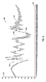
- FIG. 8 is a graph 800 of another representation of graph 700 (shown in FIG. 7 ) that shows only the normalized raw data with respect to the adiabatic curve at a smaller scale.
- Graph 800 includes an x-axis 802 graduated in units of rotational position, for example, degrees and a y-axis 804 graduated in units of normalized pressure.
- a trace 806 illustrates the adiabatic curve (shown in FIG. 7 ) that can be calculated at each increment of rotational position.
- a trace 808 illustrates the raw crank end pressure data acquired at each increment of rotational position normalized to the adiabatic curve that can be calculated at each increment of rotational position.
- traces 806 and 808 relate to anomalies in the operation of reciprocating compressor 10 that can be diagnosed visually by, for example, a human expert or may be analyzed using a processor executing instructions for characterizing the differences and correlating the analyzed characterization to known characterizations associated with known anomalies.
- a sudden swing in compression as shown at trace portion 810 may indicate a possible piston leak.
- corrective action may be alerted to an operator.
- port resonance may also be indicated over the entire curve and particularly at trace portion 812.
- FIG. 9 is a graph 900 of crank end pressure versus crank angle ⁇ during another exemplary complete compressor operation cycle of reciprocating compressor 10 (shown in FIG. 1 ).
- Graph 900 includes an x-axis 902 graduated in units of rotational position, for example, degrees and a y-axis 904 graduated in units of pressure.
- a trace 906 illustrates the raw crank end pressure data acquired at each increment of rotational position normalized to the adiabatic curve that can be calculated at each increment of rotational position.
- a trace 908 illustrates an adiabatic curve that can be calculated at each increment of rotational position.
- a trace 910 illustrates the raw crank end pressure data acquired at each increment of rotational position.
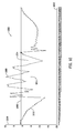
- FIG. 10 is a graph 1000 of another representation of graph 900 (shown in FIG. 9 ) that shows only the normalized raw data with respect to the adiabatic curve at a smaller scale.
- Graph 1000 includes an x-axis 1002 graduated in units of rotational position, for example, degrees and a y-axis 1004 graduated in units of normalized pressure.
- a trace 1006 illustrates the adiabatic curve (shown in FIG. 9 ) that can be calculated at each increment of rotational position.
- a trace 1008 illustrates the raw crank end pressure data acquired at each increment of rotational position normalized to the adiabatic curve that can be calculated at each increment of rotational position.
- traces 1006 and 1008 relate to anomalies in the operation of reciprocating compressor 10 that can be diagnosed visually by, for example, a human expert or may be analyzed using a processor executing instructions for characterizing the differences and correlating the analyzed characterization to known characterizations associated with known anomalies.
- a low pressure during compression as shown at trace portion 1010 may indicate a possible suction valve leak.
- valve flutter may be indicted as at trace portion 1012 and low pressure during expansion as shown at trace portion 1014 may also indicate a possible suction valve leak.
- FIG. 12 is a graph 1200 of another representation of graph 1100 (shown in FIG. 11 ) that shows only the normalized raw data with respect to the adiabatic curve at a smaller scale.
- Graph 1200 includes an x-axis 1202 graduated in units of rotational position, for example, degrees and a y-axis 1204 graduated in units of normalized pressure.
- a trace 1206 illustrates the adiabatic curve (shown in FIG. 11 ) that can be calculated at each increment of rotational position.
- a trace 1208 illustrates the raw crank end pressure data acquired at each increment of rotational position normalized to the adiabatic curve that can be calculated at each increment of rotational position.
- the accentuated difference between traces 1206 and 1208 relate to anomalies in the operation of reciprocating compressor 10 that can be diagnosed visually by, for example, a human expert or may be analyzed using a processor executing instructions for characterizing the differences and correlating the analyzed characterization to known characterizations associated with known anomalies. For example, a high pressure during compression, discharge and expansion as shown at trace portion 1208 and trace portion 1210 may indicate a discharge valve leak.
- FIG. 13 is a flowchart of an exemplary method 1300 of analyzing machinery operating parameters.
- Method 1300 is exemplary only and not limiting. Method 1300 may be altered, e.g., by having stages added, removed, or rearranged. In the exemplary embodiment, method 1300 can be implemented using a computing device coupled to a user interface and a memory device, although other embodiments are possible.
- method 1300 can include determining an ideal or adiabatic curve of a first operating parameter of a machine wherein the machine can include a plurality of component parts.
- the ideal curve can be determined using an algorithm or other electronic representation of the machine, where inputs from a plurality of sensors monitoring various process parameters relating to the operation of the machine are used as variables in the algorithm.
- method 1300 can include receiving an indication of a second operating parameter of the machine.
- the second operating parameter can include a parameter that permits correlating the ideal curve of the first operating parameter and the values of the first operating parameter as collected by the monitoring system and optionally processed in the monitoring system.
- the raw data representing the second operating parameter may be key phasor information indicating a rotational position of the shaft.
- the second operating parameter may also be linear position information indicating a position of a piston or valve.
- the method 1300 can include receiving an indication of the first operating parameter of the machine wherein the indication of the first operating parameter is correlated to the received indication of the second operating parameter.
- the second operating parameter represents a key phasor or other parameter that facilitates displaying the first operating parameter on the same graph as the ideal curve.
- the second operating parameter then represents the values along which the x-axis is plotted.
- the second operating parameter may simply represent time, where the first operating parameter and the ideal curve are plotted together along an axis graduated in units of time rather than position.
- method 1300 further can include normalizing the indication of the first operating parameter to the ideal curve of the first operating parameter. Normalizing the indication of the first operating parameter to the ideal curve may be accomplished by adjusting values of the indication of the first operating parameter and/or the ideal curve to account for different scales, or influences of other parameters over one of the first operating parameter and/or the ideal curve but not the other, or not to the same degree. In some embodiments, normalization involves only a rescaling, to arrive at values relative to some size variable.
- method 1300 further can include determining a condition of the machine based on a comparison of the normalized indication of the first operating parameter to the ideal curve of the first operating parameter.
- anomalies in the machine operation may easily be detected visually by a trained human operator. As described above various anomalous conditions of the machine exhibit characteristic signatures of related parameters. Am operator may be trained to recognize these characteristic signatures and determine the source of the anomaly. Alternatively, curve-fitting algorithms may be employed to recognize the characteristic signatures and determine many anomalous conditions electronically on a continuous basis in real-time or near real-time.
- non-transitory computer-readable media is intended to be representative of any tangible computer-based device implemented in any method or technology for short-term and long-term storage of information, such as, computer-readable instructions, data structures, program modules and sub-modules, or other data in any device. Therefore, the methods described herein may be encoded as executable instructions embodied in a tangible, non-transitory, computer readable medium, including, without limitation, a storage device and/or a memory device. Such instructions, when executed by a processor, cause the processor to perform at least a portion of the methods described herein.
- non-transitory computer-readable media can include all tangible, computer-readable media, including, without limitation, non-transitory computer storage devices, including, without limitation, volatile and nonvolatile media, and removable and non-removable media such as a firmware, physical and virtual storage, CD-ROMs, DVDs, and any other digital source such as a network or the Internet, as well as yet to be developed digital means, with the sole exception being a transitory, propagating signal.
- the term "computer” and related terms, e.g., “computing device”, are not limited to integrated circuits referred to in the art as a computer, but broadly includes a microcontroller, a microcomputer, a programmable logic controller (PLC), an application specific integrated circuit, and other programmable circuits, and these terms are used interchangeably herein.
- PLC programmable logic controller
- Approximating language may be applied to modify any quantitative representation that could permissibly vary without resulting in a change in the basic function to which it is related. Accordingly, a value modified by a term or terms, such as “about” and “substantially,” are not to be limited to the precise value specified. In at least some instances, the approximating language may correspond to the precision of an instrument for measuring the value.
- range limitations may be combined and/or interchanged, such ranges are identified and include all the sub-ranges contained therein unless context or language indicates otherwise.
- the above-described embodiments of the disclosure may be implemented using computer programming or engineering techniques including computer software, firmware, hardware or any combination or subset thereof, the technical effect of the methods and systems may be achieved by performing at least one of the following steps: (a) determining an ideal curve of a first operating parameter of a machine, the machine including a plurality of component parts, (b) receiving an indication of a second operating parameter of the machine, (c) receiving an indication of the first operating parameter of the machine, the indication of the first operating parameter correlated to the received indication of the second operating parameter, (d) normalizing the indication of the first operating parameter to the ideal curve of the first operating parameter, and (e) determining a condition of the machine based on the normalizing of the indication of the first operating parameter to the ideal curve of the first operating parameter.
- Any such resulting program, having computer-readable code means, may be embodied or provided within one or more computer-readable media, thereby making a computer program product, i.e., an article of manufacture, according to the discussed embodiments of the disclosure.
- the computer readable media may be, for example, but is not limited to, a fixed (hard) drive, diskette, optical disk, magnetic tape, semiconductor memory such as read-only memory (ROM), and/or any transmitting/receiving medium such as the Internet or other communication network or link.
- the article of manufacture containing the computer code may be made and/or used by executing the code directly from one medium, by copying the code from one medium to another medium, or by transmitting the code over a network.
- the above-described embodiments of a method and system of analyzing machinery operation provides a cost-effective and reliable means for automatically receiving, analyzing, and presenting machine operating parameters normalized to an ideal curve of the machine operating parameter to accentuate anomalies in the machine operating parameters. More specifically, the methods and systems described herein facilitate maintaining machinery. In addition, the above-described methods and systems facilitate scheduling outages relating to machinery affected by anomalies manifest by monitoring machine operating parameters. As a result, the methods and systems described herein facilitate maintaining machinery in a high state of readiness in a cost-effective and reliable manner.
- Example methods and apparatus for automatically analyzing machine operating conditions are described above in detail.
- the apparatus illustrated is not limited to the specific embodiments described herein, but rather, components of each may be utilized independently and separately from other components described herein.
- Each system component can also be used in combination with other system components.
- At least one of in reference to a plurality of elements, this is intended to mean at least one or more of the listed elements, and is not limited to at least one of each element.
- at least one of an element A, element B, and element C is intended to indicate element A alone, or element B alone, or element C alone, or any combination thereof.
- At least one of element A, element B, and element C is not intended to be limited to at least one of an element A, at least one of an element B, and at least one of an element C.
Landscapes
- Physics & Mathematics (AREA)
- General Physics & Mathematics (AREA)
- Engineering & Computer Science (AREA)
- Automation & Control Theory (AREA)
- Control Of Positive-Displacement Pumps (AREA)
Applications Claiming Priority (1)
| Application Number | Priority Date | Filing Date | Title |
|---|---|---|---|
| US14/824,457 US10775274B2 (en) | 2015-08-12 | 2015-08-12 | Analyzing machinery operating parameters |
Publications (2)
| Publication Number | Publication Date |
|---|---|
| EP3130977A1 true EP3130977A1 (fr) | 2017-02-15 |
| EP3130977B1 EP3130977B1 (fr) | 2018-10-17 |
Family
ID=56852061
Family Applications (1)
| Application Number | Title | Priority Date | Filing Date |
|---|---|---|---|
| EP16182960.1A Active EP3130977B1 (fr) | 2015-08-12 | 2016-08-05 | Analyse des paramètres de fonctionnement de machines |
Country Status (3)
| Country | Link |
|---|---|
| US (1) | US10775274B2 (fr) |
| EP (1) | EP3130977B1 (fr) |
| DK (1) | DK3130977T3 (fr) |
Families Citing this family (2)
| Publication number | Priority date | Publication date | Assignee | Title |
|---|---|---|---|---|
| US12072268B2 (en) * | 2021-10-07 | 2024-08-27 | Epro Gmbh | Automatic determination of trigger angle for reciprocating compressor rod drop measurements |
| EP4722538A1 (fr) * | 2024-10-02 | 2026-04-08 | Burckhardt Compression AG | Procédé de détermination d'un état de fonctionnement d'un compresseur alternatif |
Citations (1)
| Publication number | Priority date | Publication date | Assignee | Title |
|---|---|---|---|---|
| US20130218484A1 (en) * | 2009-04-02 | 2013-08-22 | Honeywell International Inc. | System and method for monitoring rotating and reciprocating machinery |
Family Cites Families (14)
| Publication number | Priority date | Publication date | Assignee | Title |
|---|---|---|---|---|
| US4456963A (en) | 1981-05-11 | 1984-06-26 | S & W Instruments, Inc. | Apparatus and method for measuring and displaying performance characteristics of reciprocating piston machines |
| US5471400A (en) * | 1994-05-24 | 1995-11-28 | Gas Research Institute | Method for detecting and specifying compressor cylinder leaks |
| US6292757B1 (en) | 1999-08-16 | 2001-09-18 | Windrock, Inc. | Method and apparatus for continuously monitoring parameters of reciprocating compressor cylinders |
| US20030077179A1 (en) | 2001-10-19 | 2003-04-24 | Michael Collins | Compressor protection module and system and method incorporating same |
| US7186094B2 (en) | 2003-03-26 | 2007-03-06 | Gas Machinery Research Council | Method and apparatus for measuring work performed by a compressor |
| US7056097B2 (en) | 2003-07-30 | 2006-06-06 | Equistar Chemicals L.P. | System and method for monitoring the mechanical condition of a reciprocating compressor |
| US7124057B2 (en) | 2003-08-19 | 2006-10-17 | Festo Corporation | Method and apparatus for diagnosing a cyclic system |
| US8147211B2 (en) | 2006-01-03 | 2012-04-03 | General Electric Company | Method and system for monitoring a reciprocating compressor valve |
| US7418355B2 (en) | 2006-01-03 | 2008-08-26 | General Electric Company | Method and system for monitoring a piston rod |
| US7463995B2 (en) | 2006-02-07 | 2008-12-09 | General Electric Company | Systems and methods for detecting suction valve closure |
| WO2008157498A1 (fr) | 2007-06-15 | 2008-12-24 | Shell Oil Company | Procédés et systèmes pour prédire un fonctionnement d'équipement |
| US20100256927A1 (en) * | 2009-04-06 | 2010-10-07 | General Electric Company | Methods of Detecting Valve Closure in Reciprocating Compressors |
| US8807959B2 (en) | 2010-11-30 | 2014-08-19 | General Electric Company | Reciprocating compressor and methods for monitoring operation of same |
| US20150309200A1 (en) * | 2012-11-30 | 2015-10-29 | Timur Vyacheslavowich Zharnikov | A method for processing acoustic waveforms |
-
2015
- 2015-08-12 US US14/824,457 patent/US10775274B2/en active Active
-
2016
- 2016-08-05 DK DK16182960.1T patent/DK3130977T3/en active
- 2016-08-05 EP EP16182960.1A patent/EP3130977B1/fr active Active
Patent Citations (1)
| Publication number | Priority date | Publication date | Assignee | Title |
|---|---|---|---|---|
| US20130218484A1 (en) * | 2009-04-02 | 2013-08-22 | Honeywell International Inc. | System and method for monitoring rotating and reciprocating machinery |
Non-Patent Citations (1)
| Title |
|---|
| KLEIN M ET AL: "Compression ratio estimation based on cylinder pressure data", CONTROL ENGINEERING PRACTICE, PERGAMON PRESS, OXFORD, GB, vol. 14, no. 3, 1 March 2006 (2006-03-01), pages 197 - 211, XP027906180, ISSN: 0967-0661, [retrieved on 20060301] * |
Also Published As
| Publication number | Publication date |
|---|---|
| DK3130977T3 (en) | 2019-01-28 |
| US10775274B2 (en) | 2020-09-15 |
| EP3130977B1 (fr) | 2018-10-17 |
| US20170045420A1 (en) | 2017-02-16 |
Similar Documents
| Publication | Publication Date | Title |
|---|---|---|
| US8807959B2 (en) | Reciprocating compressor and methods for monitoring operation of same | |
| EP3001034B1 (fr) | Procédé et système pour un ensemble de piston instrumenté | |
| US9528629B2 (en) | Methods and apparatus to use vibration data to determine a condition of a process control device | |
| CA2772816C (fr) | Methodes et systemes de surveillance du fonctionnement d'equipements | |
| US9695956B2 (en) | Spectral analysis based detector for a control valve | |
| US20190203736A1 (en) | Pump Monitoring | |
| CN105987822A (zh) | 用于预测装备故障的方法和系统 | |
| AU2015359243B2 (en) | Monitoring device and method for determining operating health of pressure medium operated device | |
| US10775274B2 (en) | Analyzing machinery operating parameters | |
| Naumenko et al. | The Piston Compressor: The Methodology of the Real-Time Condition Monitoring | |
| JP7716221B2 (ja) | 回転機システム、及びその診断方法 | |
| CN100453809C (zh) | 监控往复式压缩机的方法和系统 | |
| NZ599241B (en) | Methods and systems for monitoring operation of equipment |
Legal Events
| Date | Code | Title | Description |
|---|---|---|---|
| PUAI | Public reference made under article 153(3) epc to a published international application that has entered the european phase |
Free format text: ORIGINAL CODE: 0009012 |
|
| STAA | Information on the status of an ep patent application or granted ep patent |
Free format text: STATUS: THE APPLICATION HAS BEEN PUBLISHED |
|
| AK | Designated contracting states |
Kind code of ref document: A1 Designated state(s): AL AT BE BG CH CY CZ DE DK EE ES FI FR GB GR HR HU IE IS IT LI LT LU LV MC MK MT NL NO PL PT RO RS SE SI SK SM TR |
|
| AX | Request for extension of the european patent |
Extension state: BA ME |
|
| STAA | Information on the status of an ep patent application or granted ep patent |
Free format text: STATUS: REQUEST FOR EXAMINATION WAS MADE |
|
| 17P | Request for examination filed |
Effective date: 20170816 |
|
| RBV | Designated contracting states (corrected) |
Designated state(s): AL AT BE BG CH CY CZ DE DK EE ES FI FR GB GR HR HU IE IS IT LI LT LU LV MC MK MT NL NO PL PT RO RS SE SI SK SM TR |
|
| STAA | Information on the status of an ep patent application or granted ep patent |
Free format text: STATUS: EXAMINATION IS IN PROGRESS |
|
| 17Q | First examination report despatched |
Effective date: 20180119 |
|
| INTG | Intention to grant announced |
Effective date: 20180611 |
|
| GRAP | Despatch of communication of intention to grant a patent |
Free format text: ORIGINAL CODE: EPIDOSNIGR1 |
|
| STAA | Information on the status of an ep patent application or granted ep patent |
Free format text: STATUS: GRANT OF PATENT IS INTENDED |
|
| GRAS | Grant fee paid |
Free format text: ORIGINAL CODE: EPIDOSNIGR3 |
|
| GRAA | (expected) grant |
Free format text: ORIGINAL CODE: 0009210 |
|
| STAA | Information on the status of an ep patent application or granted ep patent |
Free format text: STATUS: THE PATENT HAS BEEN GRANTED |
|
| AK | Designated contracting states |
Kind code of ref document: B1 Designated state(s): AL AT BE BG CH CY CZ DE DK EE ES FI FR GB GR HR HU IE IS IT LI LT LU LV MC MK MT NL NO PL PT RO RS SE SI SK SM TR |
|
| REG | Reference to a national code |
Ref country code: GB Ref legal event code: FG4D |
|
| REG | Reference to a national code |
Ref country code: CH Ref legal event code: EP |
|
| REG | Reference to a national code |
Ref country code: IE Ref legal event code: FG4D |
|
| REG | Reference to a national code |
Ref country code: DE Ref legal event code: R096 Ref document number: 602016006451 Country of ref document: DE Ref country code: AT Ref legal event code: REF Ref document number: 1054747 Country of ref document: AT Kind code of ref document: T Effective date: 20181115 |
|
| REG | Reference to a national code |
Ref country code: DK Ref legal event code: T3 Effective date: 20190123 |
|
| REG | Reference to a national code |
Ref country code: SE Ref legal event code: TRGR |
|
| REG | Reference to a national code |
Ref country code: NL Ref legal event code: MP Effective date: 20181017 |
|
| REG | Reference to a national code |
Ref country code: LT Ref legal event code: MG4D |
|
| REG | Reference to a national code |
Ref country code: AT Ref legal event code: MK05 Ref document number: 1054747 Country of ref document: AT Kind code of ref document: T Effective date: 20181017 |
|
| PG25 | Lapsed in a contracting state [announced via postgrant information from national office to epo] |
Ref country code: NL Free format text: LAPSE BECAUSE OF FAILURE TO SUBMIT A TRANSLATION OF THE DESCRIPTION OR TO PAY THE FEE WITHIN THE PRESCRIBED TIME-LIMIT Effective date: 20181017 |
|
| PG25 | Lapsed in a contracting state [announced via postgrant information from national office to epo] |
Ref country code: BG Free format text: LAPSE BECAUSE OF FAILURE TO SUBMIT A TRANSLATION OF THE DESCRIPTION OR TO PAY THE FEE WITHIN THE PRESCRIBED TIME-LIMIT Effective date: 20190117 Ref country code: ES Free format text: LAPSE BECAUSE OF FAILURE TO SUBMIT A TRANSLATION OF THE DESCRIPTION OR TO PAY THE FEE WITHIN THE PRESCRIBED TIME-LIMIT Effective date: 20181017 Ref country code: LT Free format text: LAPSE BECAUSE OF FAILURE TO SUBMIT A TRANSLATION OF THE DESCRIPTION OR TO PAY THE FEE WITHIN THE PRESCRIBED TIME-LIMIT Effective date: 20181017 Ref country code: NO Free format text: LAPSE BECAUSE OF FAILURE TO SUBMIT A TRANSLATION OF THE DESCRIPTION OR TO PAY THE FEE WITHIN THE PRESCRIBED TIME-LIMIT Effective date: 20190117 Ref country code: IS Free format text: LAPSE BECAUSE OF FAILURE TO SUBMIT A TRANSLATION OF THE DESCRIPTION OR TO PAY THE FEE WITHIN THE PRESCRIBED TIME-LIMIT Effective date: 20190217 Ref country code: AT Free format text: LAPSE BECAUSE OF FAILURE TO SUBMIT A TRANSLATION OF THE DESCRIPTION OR TO PAY THE FEE WITHIN THE PRESCRIBED TIME-LIMIT Effective date: 20181017 Ref country code: LV Free format text: LAPSE BECAUSE OF FAILURE TO SUBMIT A TRANSLATION OF THE DESCRIPTION OR TO PAY THE FEE WITHIN THE PRESCRIBED TIME-LIMIT Effective date: 20181017 Ref country code: HR Free format text: LAPSE BECAUSE OF FAILURE TO SUBMIT A TRANSLATION OF THE DESCRIPTION OR TO PAY THE FEE WITHIN THE PRESCRIBED TIME-LIMIT Effective date: 20181017 Ref country code: PL Free format text: LAPSE BECAUSE OF FAILURE TO SUBMIT A TRANSLATION OF THE DESCRIPTION OR TO PAY THE FEE WITHIN THE PRESCRIBED TIME-LIMIT Effective date: 20181017 Ref country code: FI Free format text: LAPSE BECAUSE OF FAILURE TO SUBMIT A TRANSLATION OF THE DESCRIPTION OR TO PAY THE FEE WITHIN THE PRESCRIBED TIME-LIMIT Effective date: 20181017 |
|
| PG25 | Lapsed in a contracting state [announced via postgrant information from national office to epo] |
Ref country code: AL Free format text: LAPSE BECAUSE OF FAILURE TO SUBMIT A TRANSLATION OF THE DESCRIPTION OR TO PAY THE FEE WITHIN THE PRESCRIBED TIME-LIMIT Effective date: 20181017 Ref country code: GR Free format text: LAPSE BECAUSE OF FAILURE TO SUBMIT A TRANSLATION OF THE DESCRIPTION OR TO PAY THE FEE WITHIN THE PRESCRIBED TIME-LIMIT Effective date: 20190118 Ref country code: RS Free format text: LAPSE BECAUSE OF FAILURE TO SUBMIT A TRANSLATION OF THE DESCRIPTION OR TO PAY THE FEE WITHIN THE PRESCRIBED TIME-LIMIT Effective date: 20181017 Ref country code: PT Free format text: LAPSE BECAUSE OF FAILURE TO SUBMIT A TRANSLATION OF THE DESCRIPTION OR TO PAY THE FEE WITHIN THE PRESCRIBED TIME-LIMIT Effective date: 20190217 |
|
| REG | Reference to a national code |
Ref country code: DE Ref legal event code: R097 Ref document number: 602016006451 Country of ref document: DE |
|
| PG25 | Lapsed in a contracting state [announced via postgrant information from national office to epo] |
Ref country code: CZ Free format text: LAPSE BECAUSE OF FAILURE TO SUBMIT A TRANSLATION OF THE DESCRIPTION OR TO PAY THE FEE WITHIN THE PRESCRIBED TIME-LIMIT Effective date: 20181017 Ref country code: IT Free format text: LAPSE BECAUSE OF FAILURE TO SUBMIT A TRANSLATION OF THE DESCRIPTION OR TO PAY THE FEE WITHIN THE PRESCRIBED TIME-LIMIT Effective date: 20181017 |
|
| PLBE | No opposition filed within time limit |
Free format text: ORIGINAL CODE: 0009261 |
|
| STAA | Information on the status of an ep patent application or granted ep patent |
Free format text: STATUS: NO OPPOSITION FILED WITHIN TIME LIMIT |
|
| PG25 | Lapsed in a contracting state [announced via postgrant information from national office to epo] |
Ref country code: EE Free format text: LAPSE BECAUSE OF FAILURE TO SUBMIT A TRANSLATION OF THE DESCRIPTION OR TO PAY THE FEE WITHIN THE PRESCRIBED TIME-LIMIT Effective date: 20181017 Ref country code: SM Free format text: LAPSE BECAUSE OF FAILURE TO SUBMIT A TRANSLATION OF THE DESCRIPTION OR TO PAY THE FEE WITHIN THE PRESCRIBED TIME-LIMIT Effective date: 20181017 Ref country code: RO Free format text: LAPSE BECAUSE OF FAILURE TO SUBMIT A TRANSLATION OF THE DESCRIPTION OR TO PAY THE FEE WITHIN THE PRESCRIBED TIME-LIMIT Effective date: 20181017 Ref country code: SK Free format text: LAPSE BECAUSE OF FAILURE TO SUBMIT A TRANSLATION OF THE DESCRIPTION OR TO PAY THE FEE WITHIN THE PRESCRIBED TIME-LIMIT Effective date: 20181017 |
|
| 26N | No opposition filed |
Effective date: 20190718 |
|
| PG25 | Lapsed in a contracting state [announced via postgrant information from national office to epo] |
Ref country code: SI Free format text: LAPSE BECAUSE OF FAILURE TO SUBMIT A TRANSLATION OF THE DESCRIPTION OR TO PAY THE FEE WITHIN THE PRESCRIBED TIME-LIMIT Effective date: 20181017 |
|
| PG25 | Lapsed in a contracting state [announced via postgrant information from national office to epo] |
Ref country code: TR Free format text: LAPSE BECAUSE OF FAILURE TO SUBMIT A TRANSLATION OF THE DESCRIPTION OR TO PAY THE FEE WITHIN THE PRESCRIBED TIME-LIMIT Effective date: 20181017 |
|
| PG25 | Lapsed in a contracting state [announced via postgrant information from national office to epo] |
Ref country code: CH Free format text: LAPSE BECAUSE OF NON-PAYMENT OF DUE FEES Effective date: 20190831 Ref country code: LU Free format text: LAPSE BECAUSE OF NON-PAYMENT OF DUE FEES Effective date: 20190805 Ref country code: MC Free format text: LAPSE BECAUSE OF FAILURE TO SUBMIT A TRANSLATION OF THE DESCRIPTION OR TO PAY THE FEE WITHIN THE PRESCRIBED TIME-LIMIT Effective date: 20181017 Ref country code: LI Free format text: LAPSE BECAUSE OF NON-PAYMENT OF DUE FEES Effective date: 20190831 |
|
| REG | Reference to a national code |
Ref country code: BE Ref legal event code: MM Effective date: 20190831 |
|
| PG25 | Lapsed in a contracting state [announced via postgrant information from national office to epo] |
Ref country code: FR Free format text: LAPSE BECAUSE OF NON-PAYMENT OF DUE FEES Effective date: 20190831 Ref country code: IE Free format text: LAPSE BECAUSE OF NON-PAYMENT OF DUE FEES Effective date: 20190805 |
|
| PG25 | Lapsed in a contracting state [announced via postgrant information from national office to epo] |
Ref country code: BE Free format text: LAPSE BECAUSE OF NON-PAYMENT OF DUE FEES Effective date: 20190831 |
|
| PG25 | Lapsed in a contracting state [announced via postgrant information from national office to epo] |
Ref country code: CY Free format text: LAPSE BECAUSE OF FAILURE TO SUBMIT A TRANSLATION OF THE DESCRIPTION OR TO PAY THE FEE WITHIN THE PRESCRIBED TIME-LIMIT Effective date: 20181017 |
|
| PG25 | Lapsed in a contracting state [announced via postgrant information from national office to epo] |
Ref country code: MT Free format text: LAPSE BECAUSE OF FAILURE TO SUBMIT A TRANSLATION OF THE DESCRIPTION OR TO PAY THE FEE WITHIN THE PRESCRIBED TIME-LIMIT Effective date: 20181017 Ref country code: HU Free format text: LAPSE BECAUSE OF FAILURE TO SUBMIT A TRANSLATION OF THE DESCRIPTION OR TO PAY THE FEE WITHIN THE PRESCRIBED TIME-LIMIT; INVALID AB INITIO Effective date: 20160805 |
|
| PG25 | Lapsed in a contracting state [announced via postgrant information from national office to epo] |
Ref country code: MK Free format text: LAPSE BECAUSE OF FAILURE TO SUBMIT A TRANSLATION OF THE DESCRIPTION OR TO PAY THE FEE WITHIN THE PRESCRIBED TIME-LIMIT Effective date: 20181017 |
|
| PGFP | Annual fee paid to national office [announced via postgrant information from national office to epo] |
Ref country code: DK Payment date: 20250723 Year of fee payment: 10 Ref country code: DE Payment date: 20250724 Year of fee payment: 10 |
|
| PGFP | Annual fee paid to national office [announced via postgrant information from national office to epo] |
Ref country code: GB Payment date: 20250725 Year of fee payment: 10 |
|
| PGFP | Annual fee paid to national office [announced via postgrant information from national office to epo] |
Ref country code: SE Payment date: 20250723 Year of fee payment: 10 |